EP2469582A2 - Substrate processing method - Google Patents
Substrate processing method Download PDFInfo
- Publication number
- EP2469582A2 EP2469582A2 EP11010198A EP11010198A EP2469582A2 EP 2469582 A2 EP2469582 A2 EP 2469582A2 EP 11010198 A EP11010198 A EP 11010198A EP 11010198 A EP11010198 A EP 11010198A EP 2469582 A2 EP2469582 A2 EP 2469582A2
- Authority
- EP
- European Patent Office
- Prior art keywords
- layer
- gas
- plasma
- substrate processing
- generated
- Prior art date
- Legal status (The legal status is an assumption and is not a legal conclusion. Google has not performed a legal analysis and makes no representation as to the accuracy of the status listed.)
- Granted
Links
- 239000000758 substrate Substances 0.000 title claims abstract description 62
- 238000003672 processing method Methods 0.000 title claims abstract description 20
- 239000010949 copper Substances 0.000 claims abstract description 104
- 239000007789 gas Substances 0.000 claims abstract description 79
- 238000005530 etching Methods 0.000 claims abstract description 59
- RYGMFSIKBFXOCR-UHFFFAOYSA-N Copper Chemical compound [Cu] RYGMFSIKBFXOCR-UHFFFAOYSA-N 0.000 claims abstract description 45
- VNWKTOKETHGBQD-UHFFFAOYSA-N methane Chemical compound C VNWKTOKETHGBQD-UHFFFAOYSA-N 0.000 claims abstract description 35
- UFHFLCQGNIYNRP-UHFFFAOYSA-N Hydrogen Chemical compound [H][H] UFHFLCQGNIYNRP-UHFFFAOYSA-N 0.000 claims abstract description 31
- 229910052802 copper Inorganic materials 0.000 claims abstract description 31
- 239000001301 oxygen Substances 0.000 claims abstract description 21
- 229910052760 oxygen Inorganic materials 0.000 claims abstract description 21
- 238000000034 method Methods 0.000 claims description 80
- 238000001020 plasma etching Methods 0.000 claims description 16
- QVGXLLKOCUKJST-UHFFFAOYSA-N atomic oxygen Chemical compound [O] QVGXLLKOCUKJST-UHFFFAOYSA-N 0.000 claims description 13
- UGFAIRIUMAVXCW-UHFFFAOYSA-N Carbon monoxide Chemical compound [O+]#[C-] UGFAIRIUMAVXCW-UHFFFAOYSA-N 0.000 claims description 10
- 229910002091 carbon monoxide Inorganic materials 0.000 claims description 10
- XKRFYHLGVUSROY-UHFFFAOYSA-N Argon Chemical compound [Ar] XKRFYHLGVUSROY-UHFFFAOYSA-N 0.000 claims description 8
- 150000001722 carbon compounds Chemical class 0.000 claims description 8
- 239000000126 substance Substances 0.000 claims description 7
- 229910052786 argon Inorganic materials 0.000 claims description 5
- 150000007524 organic acids Chemical class 0.000 abstract description 27
- 238000006243 chemical reaction Methods 0.000 abstract description 17
- -1 oxygen radicals Chemical class 0.000 abstract description 15
- 229910052736 halogen Inorganic materials 0.000 abstract description 9
- 150000002367 halogens Chemical class 0.000 abstract description 9
- 150000001723 carbon free-radicals Chemical class 0.000 abstract description 6
- 210000002381 plasma Anatomy 0.000 description 42
- 239000001257 hydrogen Substances 0.000 description 16
- 229910052739 hydrogen Inorganic materials 0.000 description 16
- 239000011368 organic material Substances 0.000 description 15
- 230000006870 function Effects 0.000 description 10
- 230000008016 vaporization Effects 0.000 description 8
- 150000002500 ions Chemical class 0.000 description 7
- 238000009834 vaporization Methods 0.000 description 7
- 238000001816 cooling Methods 0.000 description 6
- 238000010586 diagram Methods 0.000 description 5
- 230000006698 induction Effects 0.000 description 5
- 229920002120 photoresistant polymer Polymers 0.000 description 5
- 150000001875 compounds Chemical class 0.000 description 4
- 238000005260 corrosion Methods 0.000 description 4
- 230000007797 corrosion Effects 0.000 description 4
- QGZKDVFQNNGYKY-UHFFFAOYSA-N Ammonia Chemical compound N QGZKDVFQNNGYKY-UHFFFAOYSA-N 0.000 description 3
- XUIMIQQOPSSXEZ-UHFFFAOYSA-N Silicon Chemical compound [Si] XUIMIQQOPSSXEZ-UHFFFAOYSA-N 0.000 description 3
- 150000002366 halogen compounds Chemical class 0.000 description 3
- 239000000463 material Substances 0.000 description 3
- 150000003254 radicals Chemical class 0.000 description 3
- 229910052710 silicon Inorganic materials 0.000 description 3
- 239000010703 silicon Substances 0.000 description 3
- OKTJSMMVPCPJKN-UHFFFAOYSA-N Carbon Chemical compound [C] OKTJSMMVPCPJKN-UHFFFAOYSA-N 0.000 description 2
- BOTDANWDWHJENH-UHFFFAOYSA-N Tetraethyl orthosilicate Chemical compound CCO[Si](OCC)(OCC)OCC BOTDANWDWHJENH-UHFFFAOYSA-N 0.000 description 2
- 229910052799 carbon Inorganic materials 0.000 description 2
- 239000004020 conductor Substances 0.000 description 2
- 238000005192 partition Methods 0.000 description 2
- 238000011160 research Methods 0.000 description 2
- 230000004044 response Effects 0.000 description 2
- 239000004065 semiconductor Substances 0.000 description 2
- IJGRMHOSHXDMSA-UHFFFAOYSA-N Atomic nitrogen Chemical compound N#N IJGRMHOSHXDMSA-UHFFFAOYSA-N 0.000 description 1
- VYPSYNLAJGMNEJ-UHFFFAOYSA-N Silicium dioxide Chemical compound O=[Si]=O VYPSYNLAJGMNEJ-UHFFFAOYSA-N 0.000 description 1
- 239000002253 acid Substances 0.000 description 1
- XAGFODPZIPBFFR-UHFFFAOYSA-N aluminium Chemical compound [Al] XAGFODPZIPBFFR-UHFFFAOYSA-N 0.000 description 1
- 229910052782 aluminium Inorganic materials 0.000 description 1
- 229910021529 ammonia Inorganic materials 0.000 description 1
- 239000000919 ceramic Substances 0.000 description 1
- 238000009833 condensation Methods 0.000 description 1
- 239000002826 coolant Substances 0.000 description 1
- 239000003989 dielectric material Substances 0.000 description 1
- 229910000069 nitrogen hydride Inorganic materials 0.000 description 1
- 230000003287 optical effect Effects 0.000 description 1
- HBMJWWWQQXIZIP-UHFFFAOYSA-N silicon carbide Chemical compound [Si+]#[C-] HBMJWWWQQXIZIP-UHFFFAOYSA-N 0.000 description 1
- 238000004544 sputter deposition Methods 0.000 description 1
- WFKWXMTUELFFGS-UHFFFAOYSA-N tungsten Chemical compound [W] WFKWXMTUELFFGS-UHFFFAOYSA-N 0.000 description 1
- 229910052721 tungsten Inorganic materials 0.000 description 1
- 239000010937 tungsten Substances 0.000 description 1
Images


Classifications
-
- H—ELECTRICITY
- H01—ELECTRIC ELEMENTS
- H01L—SEMICONDUCTOR DEVICES NOT COVERED BY CLASS H10
- H01L21/00—Processes or apparatus adapted for the manufacture or treatment of semiconductor or solid state devices or of parts thereof
- H01L21/02—Manufacture or treatment of semiconductor devices or of parts thereof
- H01L21/02041—Cleaning
- H01L21/02057—Cleaning during device manufacture
- H01L21/0206—Cleaning during device manufacture during, before or after processing of insulating layers
- H01L21/02063—Cleaning during device manufacture during, before or after processing of insulating layers the processing being the formation of vias or contact holes
-
- H—ELECTRICITY
- H01—ELECTRIC ELEMENTS
- H01L—SEMICONDUCTOR DEVICES NOT COVERED BY CLASS H10
- H01L21/00—Processes or apparatus adapted for the manufacture or treatment of semiconductor or solid state devices or of parts thereof
- H01L21/02—Manufacture or treatment of semiconductor devices or of parts thereof
- H01L21/04—Manufacture or treatment of semiconductor devices or of parts thereof the devices having at least one potential-jump barrier or surface barrier, e.g. PN junction, depletion layer or carrier concentration layer
- H01L21/18—Manufacture or treatment of semiconductor devices or of parts thereof the devices having at least one potential-jump barrier or surface barrier, e.g. PN junction, depletion layer or carrier concentration layer the devices having semiconductor bodies comprising elements of Group IV of the Periodic System or AIIIBV compounds with or without impurities, e.g. doping materials
- H01L21/30—Treatment of semiconductor bodies using processes or apparatus not provided for in groups H01L21/20 - H01L21/26
- H01L21/302—Treatment of semiconductor bodies using processes or apparatus not provided for in groups H01L21/20 - H01L21/26 to change their surface-physical characteristics or shape, e.g. etching, polishing, cutting
- H01L21/306—Chemical or electrical treatment, e.g. electrolytic etching
- H01L21/3065—Plasma etching; Reactive-ion etching
-
- C—CHEMISTRY; METALLURGY
- C23—COATING METALLIC MATERIAL; COATING MATERIAL WITH METALLIC MATERIAL; CHEMICAL SURFACE TREATMENT; DIFFUSION TREATMENT OF METALLIC MATERIAL; COATING BY VACUUM EVAPORATION, BY SPUTTERING, BY ION IMPLANTATION OR BY CHEMICAL VAPOUR DEPOSITION, IN GENERAL; INHIBITING CORROSION OF METALLIC MATERIAL OR INCRUSTATION IN GENERAL
- C23F—NON-MECHANICAL REMOVAL OF METALLIC MATERIAL FROM SURFACE; INHIBITING CORROSION OF METALLIC MATERIAL OR INCRUSTATION IN GENERAL; MULTI-STEP PROCESSES FOR SURFACE TREATMENT OF METALLIC MATERIAL INVOLVING AT LEAST ONE PROCESS PROVIDED FOR IN CLASS C23 AND AT LEAST ONE PROCESS COVERED BY SUBCLASS C21D OR C22F OR CLASS C25
- C23F4/00—Processes for removing metallic material from surfaces, not provided for in group C23F1/00 or C23F3/00
-
- H—ELECTRICITY
- H01—ELECTRIC ELEMENTS
- H01J—ELECTRIC DISCHARGE TUBES OR DISCHARGE LAMPS
- H01J37/00—Discharge tubes with provision for introducing objects or material to be exposed to the discharge, e.g. for the purpose of examination or processing thereof
- H01J37/32—Gas-filled discharge tubes
- H01J37/32009—Arrangements for generation of plasma specially adapted for examination or treatment of objects, e.g. plasma sources
- H01J37/32082—Radio frequency generated discharge
- H01J37/32091—Radio frequency generated discharge the radio frequency energy being capacitively coupled to the plasma
-
- H—ELECTRICITY
- H01—ELECTRIC ELEMENTS
- H01L—SEMICONDUCTOR DEVICES NOT COVERED BY CLASS H10
- H01L21/00—Processes or apparatus adapted for the manufacture or treatment of semiconductor or solid state devices or of parts thereof
- H01L21/02—Manufacture or treatment of semiconductor devices or of parts thereof
- H01L21/02041—Cleaning
- H01L21/02057—Cleaning during device manufacture
- H01L21/02068—Cleaning during device manufacture during, before or after processing of conductive layers, e.g. polysilicon or amorphous silicon layers
-
- H—ELECTRICITY
- H01—ELECTRIC ELEMENTS
- H01L—SEMICONDUCTOR DEVICES NOT COVERED BY CLASS H10
- H01L21/00—Processes or apparatus adapted for the manufacture or treatment of semiconductor or solid state devices or of parts thereof
- H01L21/02—Manufacture or treatment of semiconductor devices or of parts thereof
- H01L21/04—Manufacture or treatment of semiconductor devices or of parts thereof the devices having at least one potential-jump barrier or surface barrier, e.g. PN junction, depletion layer or carrier concentration layer
- H01L21/18—Manufacture or treatment of semiconductor devices or of parts thereof the devices having at least one potential-jump barrier or surface barrier, e.g. PN junction, depletion layer or carrier concentration layer the devices having semiconductor bodies comprising elements of Group IV of the Periodic System or AIIIBV compounds with or without impurities, e.g. doping materials
- H01L21/30—Treatment of semiconductor bodies using processes or apparatus not provided for in groups H01L21/20 - H01L21/26
- H01L21/31—Treatment of semiconductor bodies using processes or apparatus not provided for in groups H01L21/20 - H01L21/26 to form insulating layers thereon, e.g. for masking or by using photolithographic techniques; After treatment of these layers; Selection of materials for these layers
- H01L21/3205—Deposition of non-insulating-, e.g. conductive- or resistive-, layers on insulating layers; After-treatment of these layers
- H01L21/321—After treatment
- H01L21/3213—Physical or chemical etching of the layers, e.g. to produce a patterned layer from a pre-deposited extensive layer
- H01L21/32133—Physical or chemical etching of the layers, e.g. to produce a patterned layer from a pre-deposited extensive layer by chemical means only
- H01L21/32135—Physical or chemical etching of the layers, e.g. to produce a patterned layer from a pre-deposited extensive layer by chemical means only by vapour etching only
- H01L21/32136—Physical or chemical etching of the layers, e.g. to produce a patterned layer from a pre-deposited extensive layer by chemical means only by vapour etching only using plasmas
-
- H—ELECTRICITY
- H01—ELECTRIC ELEMENTS
- H01L—SEMICONDUCTOR DEVICES NOT COVERED BY CLASS H10
- H01L21/00—Processes or apparatus adapted for the manufacture or treatment of semiconductor or solid state devices or of parts thereof
- H01L21/02—Manufacture or treatment of semiconductor devices or of parts thereof
- H01L21/04—Manufacture or treatment of semiconductor devices or of parts thereof the devices having at least one potential-jump barrier or surface barrier, e.g. PN junction, depletion layer or carrier concentration layer
- H01L21/18—Manufacture or treatment of semiconductor devices or of parts thereof the devices having at least one potential-jump barrier or surface barrier, e.g. PN junction, depletion layer or carrier concentration layer the devices having semiconductor bodies comprising elements of Group IV of the Periodic System or AIIIBV compounds with or without impurities, e.g. doping materials
- H01L21/30—Treatment of semiconductor bodies using processes or apparatus not provided for in groups H01L21/20 - H01L21/26
- H01L21/31—Treatment of semiconductor bodies using processes or apparatus not provided for in groups H01L21/20 - H01L21/26 to form insulating layers thereon, e.g. for masking or by using photolithographic techniques; After treatment of these layers; Selection of materials for these layers
- H01L21/3205—Deposition of non-insulating-, e.g. conductive- or resistive-, layers on insulating layers; After-treatment of these layers
- H01L21/321—After treatment
- H01L21/3213—Physical or chemical etching of the layers, e.g. to produce a patterned layer from a pre-deposited extensive layer
- H01L21/32133—Physical or chemical etching of the layers, e.g. to produce a patterned layer from a pre-deposited extensive layer by chemical means only
- H01L21/32135—Physical or chemical etching of the layers, e.g. to produce a patterned layer from a pre-deposited extensive layer by chemical means only by vapour etching only
- H01L21/32138—Physical or chemical etching of the layers, e.g. to produce a patterned layer from a pre-deposited extensive layer by chemical means only by vapour etching only pre- or post-treatments, e.g. anti-corrosion processes
-
- H—ELECTRICITY
- H01—ELECTRIC ELEMENTS
- H01L—SEMICONDUCTOR DEVICES NOT COVERED BY CLASS H10
- H01L21/00—Processes or apparatus adapted for the manufacture or treatment of semiconductor or solid state devices or of parts thereof
- H01L21/70—Manufacture or treatment of devices consisting of a plurality of solid state components formed in or on a common substrate or of parts thereof; Manufacture of integrated circuit devices or of parts thereof
- H01L21/71—Manufacture of specific parts of devices defined in group H01L21/70
- H01L21/768—Applying interconnections to be used for carrying current between separate components within a device comprising conductors and dielectrics
- H01L21/76801—Applying interconnections to be used for carrying current between separate components within a device comprising conductors and dielectrics characterised by the formation and the after-treatment of the dielectrics, e.g. smoothing
- H01L21/76802—Applying interconnections to be used for carrying current between separate components within a device comprising conductors and dielectrics characterised by the formation and the after-treatment of the dielectrics, e.g. smoothing by forming openings in dielectrics
- H01L21/76805—Applying interconnections to be used for carrying current between separate components within a device comprising conductors and dielectrics characterised by the formation and the after-treatment of the dielectrics, e.g. smoothing by forming openings in dielectrics the opening being a via or contact hole penetrating the underlying conductor
Definitions
- the present disclosure relates to a substrate processing method for etching copper by plasma and also relates to a storage medium.
- a halogen gas, a halogen compound gas or a gas containing an ammonia (NH 3 ) gas or a nitrogen (N 2 ) gas in addition to the halogen gas or the halogen compound gas have been used as a processing gas in a high temperature environment. Since, however, the halogen gas or the halogen compound gas generates strong acid, components of a substrate processing apparatus easily corrodes in the high temperature environment.
- Non-Patent Document 1 a method for etching a wiring or a layer made of copper (hereinafter, referred to as a "copper member") by plasma without using a halogen gas as a processing gas.
- a hydrogen gas is used as a processing gas, and a vacuum ultraviolet ray having a wavelength of about 100 nm is generated when the hydrogen plasma is generated.
- a chemical reaction between hydrogen plasma and copper is facilitated by irradiation of the vacuum ultraviolet ray.
- a compound of copper and hydrogen is generated.
- copper is etched by vaporizing the compound of hydrogen and copper.
- Non-Patent Document 1 Fangyu Wu, Galit Levitin, and Dennis W.Hess, "Low-Temperature Etching of Cu by Hydrogen-Based Plasmas", ACS APPLIED MATERIALS INTERFA CES, VOL.2, NO.8, 2175-2179, 2010, published on July 16, 2010
- the present disclosure provides a substrate processing method capable of increasing an etching rate of a copper member without using a halogen gas.
- a substrate processing method performed in a substrate processing apparatus for performing a plasma etching process on a substrate.
- the substrate processing method includes performing a main etching process that generates plasma from a processing gas produced by adding a gas of a carbon compound to a hydrogen gas, and etches a copper member of the substrate by the plasma.
- the substrate processing method may further include, prior to performing a main etching process, performing an oxygen-containing layer etching process for etching an oxygen-containing layer of the substrate.
- the substrate processing method may further include, after performing an oxygen-containing layer etching process and before performing a main etching process, performing a foreign substance removing process for removing a foreign substance from a surface of the copper member.
- plasma may be generated from a processing gas produced by adding a rare gas to a hydrogen gas.
- the rare gas may be an argon gas.
- the carbon compound may be methane or carbon monoxide.
- the substrate processing apparatus may be a capacitively coupled substrate processing apparatus including two facing electrodes parallel to each other.
- the plasma is generated between the two electrodes, and the plasma etching process is performed on the substrate mounted on one of the two electrodes by using the plasma.
- the copper member is etched by the plasma generated from the processing gas produced by adding the carbon compound gas to the hydrogen gas. Accordingly, since carbon radicals as well as the hydrogen plasma exist in the etching of the copper member, a great amount of organic acid complex containing copper atoms may be generated from the copper member. Further, since the organic acid complex is readily vaporized, it is possible to remove a large number of copper atoms from the copper member. Thus, it may be possible to improve an etching rate of the copper member without using a halogen gas.
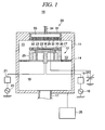
- Fig. 1 is a schematic configuration view of a substrate processing apparatus configured to perform a substrate processing method in accordance with an illustrative embodiment of the present disclosure.
- the substrate processing apparatus performs a plasma etching process on a wafer as a substrate for a semiconductor device (hereinafter, simply referred to as a "wafer").
- a substrate processing apparatus 10 includes a chamber 11 for accommodating therein a wafer W having a diameter of, e.g., about 300 mm.
- a circular column-shaped susceptor 12 for mounting thereon the wafer W is provided in the chamber 11.
- a side exhaust path 13 is formed between an inner sidewall of the chamber 11 and a side surface of the susceptor 12.
- An exhaust plate 14 is provided on the way of the side exhaust path 13.
- the exhaust plate 14 is a plate-shaped member having a multiple number of through holes.
- the exhaust plate 14 serves as a partition plate that partitions the inside of the chamber 11 into an upper portion and a lower portion.
- plasma is generated in an inner space within the upper portion 15 (hereinafter, referred to as a "processing chamber") of the chamber 11 above the exhaust plate 14.
- an exhaust pipe 17 for exhausting a gas within the chamber 11 is connected to the lower portion 16 (hereinafter, referred to as an "exhaust chamber (manifold)" of the inside of the chamber 11 below the exhaust plate 14.
- the exhaust plate 14 confines or reflects the plasma generated in the processing chamber 15, thus preventing leakage of the plasma into the manifold 16.
- the exhaust pipe 17 is connected with a TMP (Turbo Molecular Pump) and a DP (Dry Pump) (both are not shown). These pumps evacuate and depressurize the inside of the chamber 11.
- the DP depressurizes the inside of the chamber 11 to an intermediate vacuum state (e.g., about 1.3 ⁇ 10 Pa (0.1 Torr) or less) from an atmospheric pressure.
- the TMP further depressurizes the inside of the chamber 11 to a high vacuum state (e.g., about 1.3 ⁇ 10 -3 Pa (1.0 ⁇ 10 -5 Torr) or less) lower than the intermediate pressure state.
- the internal pressure of the chamber 11 is controlled by an APC valve (not shown).
- the susceptor 12 within the chamber 11 is connected with a first high frequency power supply 18 via a first matching unit 19 and also connected with a second high frequency power supply 20 via a second matching unit 21.
- the first high frequency power supply 18 is configured to apply a high frequency power of a relatively low frequency for ion attraction (e.g., about 13 MHz) to the susceptor 12
- the second high frequency power supply 20 is configured to apply a high frequency power of a relatively high frequency for plasma generation (e.g., about 40 MHz) to the susceptor 12.
- the susceptor 12 may serve as an electrode.
- the first and second matching units 19 and 21 may reduce reflection of the high frequency powers from the susceptor 12, thus improving the efficiency of applying the high frequency powers to the susceptor 12.
- a step-shaped portion is formed at a periphery of a top portion of the susceptor 12 such that a central portion of the susceptor 12 protrudes upward.
- an electrostatic chuck 23 made of ceramics and having an electrostatic electrode plate 22 therein.
- the electrostatic electrode plate 22 is connected with a DC power supply 24. If a positive DC voltage is applied to the electrostatic electrode plate 22, a negative potential would be generated in a surface (hereinafter, referred to as a "rear surface") of the wafer W facing the electrostatic chuck 23. Therefore, a potential difference is generated between the electrostatic electrode plate 22 and the rear surface of the wafer W. As a result, the wafer W can be attracted to and held on the electrostatic chuck 23 by a Coulomb force or a Johnsen-Rahbek force generated by the potential difference.
- the susceptor 12 has therein a cooling device (not shown) of a coolant path.
- the cooling device is configured to absorb, via the susceptor 12, heat of the wafer W of which temperature increases as a result of its contact with the plasma. Therefore, the temperature of the wafer W is prevented from increasing over a desired level.
- the susceptor 12 may be made of a conductor such as aluminum in consideration of its heat transfer efficiency or its function as an electrode. Further, in order to prevent the conductor from being exposed to the processing chamber 15 in which the plasma is generated, disposed at the side surface of the susceptor 12 is a side protection member 25 made of a dielectric material such as, but not limited to, quartz (SiO 2 ) .
- a focus ring 26 is placed on the step-shaped portion of the susceptor 12 and the side protection member 25 so as to surround the wafer W attracted to and held on the electrostatic chuck 23.
- a shield ring 27 is placed on the side protection member 25 so as to surround the focus ring 26.
- the focus ring 26 is made of silicon (Si) or silicon carbide (SiC), and, thus, a distribution range of the plasma can be expanded to above the focus ring 26 as well as above the wafer W.
- a shower head 28 is provided at a ceiling of the chamber 11 so as to face the susceptor 12.
- the shower head 28 includes an upper electrode plate 29; a cooling plate 30 that supports the upper electrode plate 29 in a detachable manner; and a cover 31 that covers the cooling plate 30.
- the upper electrode plate 29 is a circular plate-shaped member having a multiple number of gas holes 32 formed in a thickness direction thereof.
- a buffer room 33 is formed within the cooling plate 30, and a processing gas inlet pipe 34 is connected to the buffer room 33.
- the shower head 28 and the susceptor 12 are arranged such that top surfaces of the upper electrode plate 29 and the susceptor 12 are parallel to each other.
- the substrate processing apparatus 10 also includes a controller 35.
- the controller 35 implements the plasma etching process by controlling an operation of each component of the substrate processing apparatus 10 based on programs stored in a memory embedded therein. To be more specific, the controller 35 controls the operation of each component as follows.
- a processing gas supplied into the buffer room 33 via the processing gas inlet pipe 34 is introduced into the inner space of the processing chamber 15.
- the introduced processing gas is excited into plasma by the high frequency power for plasma generation applied into the inner space of the processing chamber 15 from the second high frequency power supply 20 via the susceptor 12. Ions in the plasma are attracted toward the wafer W by the high frequency power for ion attraction applied to the susceptor 12 from the first high frequency power supply 18, and, thus, the plasma etching process is performed on the wafer W.
- Fig. 2 is a partial cross sectional view schematically illustrating a structure of a substrate on which a plasma etching process is performed by the substrate processing apparatus shown in Fig. 1 .
- Fig. 2(A) illustrates a substrate structure before the plasma etching process is performed
- Fig. 2(B) illustrates a substrate structure after the plasma etching process is performed.
- the wafer W has, on a base 36 made of silicon, a TEOS (Tetra Ethyl Ortho Silicate) layer 37, a low-k layer 38, a tungsten (Ta) layer 39, a Cu layer 40 (copper member), a low-k layer 41, an oxide layer 42 (an oxygen-containing layer), an organic dielectric (ODL) layer 43, a Si-ARC layer 44 and a photoresist layer 45 that are stacked in sequence from the bottom.
- the low-k layer 38 is made of, e.g., BLOk (a product name produced by Applied Materials, Inc.).
- the Si-ARC layer 44 serves as a hard mask and an antireflection film.
- the photoresist layer 45 has a preset opening pattern.
- the photoresist layer 45, the Si-ARC layer 44 and the organic dielectric layer 43 are etched, and the opening pattern of the photoresist layer 45 is transcribed to the oxide layer 42 and the low-k layer 41. As a result, a part of the Cu layer 40 is exposed ( Fig. 2(B) ).
- an organic material 46 generated by the etching of the organic dielectric layer 43 and an oxide (not shown) generated by the etching of the oxide layer 42 or the low-k layer 41 are partially deposited on an exposed surface of the Cu layer 40. Further, an oxide 47 such as CuO generated by the reaction between the part of the surface of the Cu layer 40 and oxygen in the processing chamber 15 is formed in the surface of the Cu layer 40. Since the organic material 46 or the oxide 47 cannot be etched by hydrogen plasma, the organic material 46 or the oxide 47 serves as a mask in a main etching of the Cu layer 40. As a result, portions of the Cu layer 40 covered with the organic material 46 or the oxide 47 are prevented from being etched, and an etching rate of the Cu layer 40 becomes lowered.
- the present inventor has conducted many researches and found out that it is possible to increase the etching rate of the Cu layer 40 without using a halogen gas by performing, prior to the main etching of the Cu layer 40, a plasma etching process on the wafer W by using plasma generated from a processing gas produced by adding a rare gas to a hydrogen gas, then, by performing, in the main etching of the Cu layer 40, a plasma etching process on the wafer W by using plasma generated from a processing gas produced by adding a carbon compound gas to a hydrogen gas, such as a methane (CH 4 ) gas or a carbon monoxide (CO) gas.
- a hydrogen gas such as a methane (CH 4 ) gas or a carbon monoxide (CO) gas.
- Figs. 3(A) to 3(C) are process diagrams for illustrating a process of etching the organic material or oxide on the surface of the Cu layer.
- the organic material 46 generated by the etching of the organic dielectric layer 43 or oxygen generated by the etching of the oxide layer 42 floats around in the inner space of the processing chamber 15.
- the organic material 46 adheres to some positions on the surface of the Cu layer 40, and the oxide 47 is generated at some positions in the surface of the Cu layer 40. That is, the organic material 46 or the oxide 47 partially exists on the surface of the Cu layer 40.
- a processing gas produced by adding a rare gas such as argon (Ar) to a hydrogen gas is introduced into the inner space of the processing chamber 15. Plasma is generated from this processing gas.
- argon (Ar) a rare gas
- positive argon ions 48 generated from the processing gas are attracted into the Cu layer 40 by a high frequency power for ion attraction applied to the susceptor 12 and sputter the entire surface of the Cu layer 40. Since, however, copper cannot be sputtered and etched by the positive ions of the rare gas, only the organic material 46 or the oxide 47 is selectively removed ( Fig. 3(B) ).
- portions of the Cu layer 40 from which the oxide 47 is removed may be left as grooves, and the surface of the Cu layer 40 may be roughened.
- hydrogen radicals 49 are generated from the processing gas and a vacuum ultraviolet ray generated when the plasma is generated from the processing gas is irradiated to the surface of the Cu layer 40. Accordingly, a chemical reaction between the hydrogen radicals 49 and copper progresses to some extent, and, thus, the surface of the Cu layer 40 is also etched by vaporization of a compound of copper and hydrogen ( Fig. 3(B) ), though an etching amount thereof is very small.
- the Cu layer 40 having a smoothened surface 50 ( Fig. 3(C) ).
- the organic material 46 or the oxide 47 does not serve as a mask and, hence, the etching of the Cu layer 40 is not impeded.
- Figs. 4(A) to 4(C) are process diagrams for illustrating the main etching process of the Cu layer.
- a processing gas produced by adding a carbon compound, e.g., a methane gas, to a hydrogen gas is introduced into the inner space of the processing chamber 15. Plasma is generated from this processing gas.
- the oxygen radicals 52 and the carbon radicals 53 are compounded to generate organic acid, and the organic acid makes a reaction with copper atoms of the Cu layer 40.
- a complex of the organic acid having the copper atoms, such as Cu(COO) is generated. Since the reaction between the organic acid and the copper atoms is a corrosion reaction, the reaction takes place relatively easily. Further, since a saturation vapor pressure of the generated organic acid complex is low, the organic acid complex is vaporized even under a low-temperature and low-pressure condition ( Fig. 4(B) ). Accordingly, through the vaporization of the organic acid complex, the copper atoms can be removed from the Cu layer 40. That is, it is possible to etch the Cu layer 40 chemically.
- the generation of the organic acid complex having the copper atoms and the vaporization of the organic acid complex continue for a preset time, e.g., about 1200 seconds, and the main etching process is completed.
- a trench 54 or hole having a preset depth can be formed in the Cu layer 40 ( Fig. 4(C) ).
- a flow rate ratio of the methane gas to the hydrogen gas may be set to be in the range of, desirably, about 2.5% to about 12.5%, and, more desirably, about 5% to about 10%.
- a flow rate of the hydrogen gas is about 400 sccm
- a flow rate of the methane gas may be set to be in the range of, desirably, about 10 sccm to about 50 sccm, and, more desirably, about 20 sccm to about 40 sccm.
- a flow rate ratio of the carbon monoxide gas to the hydrogen gas may be set to be in the range of, desirably, about 25% to about 75%, and, more desirably, about 37.5% to about 62.5% in order to etch the Cu layer 40 at a high etching rate while suppressing generation of deposits.
- a flow rate of the hydrogen gas is about 400 sccm
- a flow rate of the carbon monoxide gas may be set to be in the range of, desirably, about 100 sccm to about 300 sccm, and, more desirably, about 150 sccm to about 250 sccm.
- a corrosion reaction between the organic acid and the copper atoms is made. Since the corrosion reaction takes place relatively easily, it is not necessary to heat the wafer W to facilitate the reaction. Instead, the temperature of the susceptor 12 only needs to be set to be in the range of, e.g., about a room temperature (about 20°) to about 60° by the cooling device of the susceptor 12.
- the Cu layer 40 is etched not only by the generation of the organic acid complex having the copper atoms and the vaporization of the organic acid complex but also by the chemical reaction between the hydrogen radicals 49 and the copper. Since energy by irradiation of a vacuum ultraviolet ray is required for the chemical reaction between the hydrogen plasma and the copper, an etching rate of the Cu layer 40 by the chemical reaction between the hydrogen plasma and the copper may become nonuniform if a distribution of an irradiation amount of the vacuum ultraviolet ray is not uniform.
- a spiral induction coil 55 is provided at a top portion of a chamber 11 and a high frequency power is applied to the induction coil 55. Since plasma 57 is generated in a region corresponding to the induction coil 55, an irradiation amount of the vacuum ultraviolet ray becomes increased in a region corresponding to the induction coil 55. As a result, an etching rate of a portion of the Cu layer 40 facing the induction coil 55 becomes increased, resulting in a failure to etch the entire Cu layer 40 uniformly.
- the substrate processing apparatus 10 that performs the process of Figs. 4(A) to 4(C) is configured as a capacitively coupled plasma processing apparatus as illustrated in Fig. 5(A) .
- plasma is generated in a substantially uniform manner between the upper electrode plate and the top surface of the susceptor that are arranged to face each other. That is, the plasma 58 can be uniformly distributed between the upper electrode plate 29 and the susceptor 12.
- the distribution of the irradiation amount of the vacuum ultraviolet ray can also be made uniform, and, thus, the entire Cu layer 40 on the wafer W can be etched uniformly.
- Fig. 6 is a flowchart for illustrating a Cu layer etching process which is a substrate processing method in accordance with the present embodiment.
- the Cu layer etching process is performed while the controller 35 controls each component of the substrate processing apparatus 10 according to preset programs.
- the Si-ARC layer 44, the organic dielectric layer 43, the oxide layer 42 and the low-k layer 41 are etched by using the photoresist layer 45 as a mask (step S61) (oxygen-containing layer etching process).
- step S61 oxygen-containing layer etching process
- the oxygen radicals 52 are generated in the inner space of the processing chamber 15.
- the low-k layer 41 is etched and removed, the Cu layer 40 is exposed.
- the organic material 46 or the oxide 47 may be partially provided, as mentioned above ( Fig. 3(A) ).
- step S62 an oxide and organic material etching process, which is the process described in Figs. 3(A) to 3(C) , is performed (step S62) (foreign substance removing process). Further, the surface of the Cu layer 40 is also etched in a very small amount, so that the Cu layer 40 having the smoothened surface 50 is obtained ( Fig. 3(C) ).
- a Cu layer main etching process which is the process described in Figs. 4(A) to 4(C) , is performed (step S63) (main etching process).
- step S63 main etching process
- the trench 54 or hole of the preset depth is formed in the Cu layer 40 ( Fig. 4(C) ).
- the process is completed.
- the Cu layer 40 is chemically etched by the plasma generated from the processing gas produced by adding the methane gas and the hydrogen gas. Accordingly, during the etching of the Cu layer 40, since the carbon radicals 53 as well as the hydrogen radicals 49 exist, a great amount of organic acid complex having copper atoms is generated from the Cu layer 40. Since the organic acid complex is readily vaporized, it is possible to chemically remove a large number of copper atoms from the Cu layer 40. Thus, the etching rate of the Cu layer 40 can be improved.
- the oxide layer 42 or the like is etched prior to the main etching process of the Cu layer 40, the oxygen radicals 52 exist during the main etching process of the Cu layer 40. Accordingly, the organic acid complex can be surely generated.
- the oxide 47 or the organic material 46 is removed from the surface of the Cu layer 40 prior to the main etching process of the Cu layer 40, there exists no matter that impedes the main etching process of the Cu layer 40. Accordingly, the etching rate of the Cu layer 40 can be further enhanced.
- the structure of the substrate processing apparatus 10 can be simplified.
- the oxygen radicals 52 are generated in the inner space of the processing chamber 15.
- a processing gas produced by adding, to a hydrogen gas, an oxygen-containing gas as well as a methane gas may not be limited to the methane gas or the carbon monoxide gas, but any carbon-containing gas, e.g., a carbon compound gas may be used.
- the high frequency power for ion attraction and the high frequency power for plasma generation are added to the susceptor 12.
- a high frequency power of, e.g., about 13 MHz for ion attraction to the susceptor 12 and to apply a high frequency power of, e.g., about 60 MHz for plasma generation to the upper electrode plate 29.
- the objects of the present disclosure can be achieved by supplying a storage medium storing a software program for implementing the function of the aforementioned embodiment to a computer or the like, and by causing a CPU of the computer to read out and execute the program stored in the storage medium.
- the program itself read out from the storage medium may implement the functions of the aforementioned embodiment, and the present disclosure may be embodied by the program and the storage medium storing the program.
- the storage medium for storing therein the program may be a RAM, a NV-RAM, a floppy (registered trademark) disk, a hard disk, a magnetooptical disk, an optical disk such as a CD-ROM, a CD-R, a CD-RW, a DVD (a DVD-ROM, a DVD-RAM, a DVD-RW, a DVD+RW), a magnetic tape, a nonvolatile memory card, another ROM, or the like.
- the program may be supplied into the computer by downloading it from another computer or database, or a computer (not shown) connected to the Internet, a commercial network, a local area network (LAN) or the like.
- each embodiment described above can be implemented by executing the program read by the CPU of the computer, and an OS (operating system) operated on the CPU may perform a part or all of the actual process in response to instructions of the program and the function of each embodiment may be implemented by the process.
- OS operating system
- the program read from the storage medium may be written in a memory of a function extension board inserted into the computer or a function extension unit connected to the computer, and a CPU of the function extension board or the function extension unit may perform a part or all of the actual process in response to instructions of the program, and the function of each embodiment may be implemented by the process.
- the program may include an object code, a program executable by an interpreter, script data supplied to an OS, or the like.
Abstract
Description
- The present disclosure relates to a substrate processing method for etching copper by plasma and also relates to a storage medium.
- In order to etch copper (Cu) widely used as a wiring material for a semiconductor device, a halogen gas, a halogen compound gas or a gas containing an ammonia (NH3) gas or a nitrogen (N2) gas in addition to the halogen gas or the halogen compound gas have been used as a processing gas in a high temperature environment. Since, however, the halogen gas or the halogen compound gas generates strong acid, components of a substrate processing apparatus easily corrodes in the high temperature environment.
- In view of this problem, there has been proposed a method for etching a wiring or a layer made of copper (hereinafter, referred to as a "copper member") by plasma without using a halogen gas as a processing gas (see, for example, Non-Patent Document 1). In this method, only a hydrogen gas is used as a processing gas, and a vacuum ultraviolet ray having a wavelength of about 100 nm is generated when the hydrogen plasma is generated. Further, a chemical reaction between hydrogen plasma and copper is facilitated by irradiation of the vacuum ultraviolet ray. As a result, a compound of copper and hydrogen is generated. Then, copper is etched by vaporizing the compound of hydrogen and copper.
- Non-Patent Document 1: Fangyu Wu, Galit Levitin, and Dennis W.Hess, "Low-Temperature Etching of Cu by Hydrogen-Based Plasmas", ACS APPLIED MATERIALS INTERFA CES, VOL.2, NO.8, 2175-2179, 2010, published on July 16, 2010
- In the above method, however, an etching rate of the copper member is low and, thus, the method has been considered to be lack of practicality.
- In view of the foregoing problem, the present disclosure provides a substrate processing method capable of increasing an etching rate of a copper member without using a halogen gas.
- In accordance with an aspect of the present disclosure, there is provided a substrate processing method performed in a substrate processing apparatus for performing a plasma etching process on a substrate. The substrate processing method includes performing a main etching process that generates plasma from a processing gas produced by adding a gas of a carbon compound to a hydrogen gas, and etches a copper member of the substrate by the plasma.
- The substrate processing method may further include, prior to performing a main etching process, performing an oxygen-containing layer etching process for etching an oxygen-containing layer of the substrate.
- The substrate processing method may further include, after performing an oxygen-containing layer etching process and before performing a main etching process, performing a foreign substance removing process for removing a foreign substance from a surface of the copper member.
- In performing a foreign substance removing process, plasma may be generated from a processing gas produced by adding a rare gas to a hydrogen gas.
- Further, the rare gas may be an argon gas.
- Furthermore, the carbon compound may be methane or carbon monoxide.
- The substrate processing apparatus may be a capacitively coupled substrate processing apparatus including two facing electrodes parallel to each other. Here, the plasma is generated between the two electrodes, and the plasma etching process is performed on the substrate mounted on one of the two electrodes by using the plasma.
- In accordance with the present disclosure, the copper member is etched by the plasma generated from the processing gas produced by adding the carbon compound gas to the hydrogen gas. Accordingly, since carbon radicals as well as the hydrogen plasma exist in the etching of the copper member, a great amount of organic acid complex containing copper atoms may be generated from the copper member. Further, since the organic acid complex is readily vaporized, it is possible to remove a large number of copper atoms from the copper member. Thus, it may be possible to improve an etching rate of the copper member without using a halogen gas.
- Non-limiting and non-exhaustive embodiments will be described in conjunction with the accompanying drawings. Understanding that these drawings depict only several embodiments in accordance with the disclosure and are, therefore, not to be intended to limit its scope, the disclosure will be described with specificity and detail through use of the accompanying drawings, in which:
-
Fig. 1 is a schematic configuration view of a substrate processing apparatus configured to perform a substrate processing method in accordance with an illustrative embodiment of the present disclosure; -
Fig. 2 is a partial cross sectional view schematically illustrating a structure of a substrate on which a plasma etching process is performed by the substrate processing apparatus ofFig. 1 ,Fig. 2(A) shows a substrate structure before the plasma etching process is performed, andFig. 2(B) shows a substrate structure after the plasma etching process is performed; -
Fig. 3 shows process diagrams for illustrating a process of removing an organic material or an oxide on a surface of a Cu layer; -
Fig. 4 shows process diagrams for illustrating a main etching process of the Cu layer; -
Fig. 5 is a diagram for describing a plasma generation state in a substrate processing apparatus,Fig. 5(A) illustrates a plasma generation state in a capacitively coupled substrate processing apparatus, andFig. 5(B) illustrates a plasma generation state in an inductively coupled substrate processing apparatus; and -
Fig. 6 is flowchart for describing a Cu layer etching process which is a substrate processing method in accordance with the illustrative embodiment of the present disclosure. - Hereinafter, illustrative embodiments of the present disclosure will be described with reference to the accompanying drawings.
-
Fig. 1 is a schematic configuration view of a substrate processing apparatus configured to perform a substrate processing method in accordance with an illustrative embodiment of the present disclosure. In accordance with the illustrative embodiment of the present disclosure, the substrate processing apparatus performs a plasma etching process on a wafer as a substrate for a semiconductor device (hereinafter, simply referred to as a "wafer"). - In
Fig. 1 , asubstrate processing apparatus 10 includes achamber 11 for accommodating therein a wafer W having a diameter of, e.g., about 300 mm. A circular column-shaped susceptor 12 for mounting thereon the wafer W is provided in thechamber 11. In thissubstrate processing apparatus 10, aside exhaust path 13 is formed between an inner sidewall of thechamber 11 and a side surface of thesusceptor 12. Anexhaust plate 14 is provided on the way of theside exhaust path 13. - The
exhaust plate 14 is a plate-shaped member having a multiple number of through holes. Theexhaust plate 14 serves as a partition plate that partitions the inside of thechamber 11 into an upper portion and a lower portion. As will be described later, plasma is generated in an inner space within the upper portion 15 (hereinafter, referred to as a "processing chamber") of thechamber 11 above theexhaust plate 14. Further, anexhaust pipe 17 for exhausting a gas within thechamber 11 is connected to the lower portion 16 (hereinafter, referred to as an "exhaust chamber (manifold)") of the inside of thechamber 11 below theexhaust plate 14. Theexhaust plate 14 confines or reflects the plasma generated in theprocessing chamber 15, thus preventing leakage of the plasma into themanifold 16. - The
exhaust pipe 17 is connected with a TMP (Turbo Molecular Pump) and a DP (Dry Pump) (both are not shown). These pumps evacuate and depressurize the inside of thechamber 11. To elaborate, the DP depressurizes the inside of thechamber 11 to an intermediate vacuum state (e.g., about 1.3 × 10 Pa (0.1 Torr) or less) from an atmospheric pressure. Further, in cooperation with the DP, the TMP further depressurizes the inside of thechamber 11 to a high vacuum state (e.g., about 1.3 × 10⁻³ Pa (1.0 × 10⁻⁵ Torr) or less) lower than the intermediate pressure state. The internal pressure of thechamber 11 is controlled by an APC valve (not shown). - The
susceptor 12 within thechamber 11 is connected with a first highfrequency power supply 18 via afirst matching unit 19 and also connected with a second highfrequency power supply 20 via asecond matching unit 21. The first highfrequency power supply 18 is configured to apply a high frequency power of a relatively low frequency for ion attraction (e.g., about 13 MHz) to thesusceptor 12, and the second highfrequency power supply 20 is configured to apply a high frequency power of a relatively high frequency for plasma generation (e.g., about 40 MHz) to thesusceptor 12. In this configuration, thesusceptor 12 may serve as an electrode. Further, the first and secondmatching units susceptor 12, thus improving the efficiency of applying the high frequency powers to thesusceptor 12. - A step-shaped portion is formed at a periphery of a top portion of the
susceptor 12 such that a central portion of thesusceptor 12 protrudes upward. Provided at a top end of the central portion of thesusceptor 12 is anelectrostatic chuck 23 made of ceramics and having anelectrostatic electrode plate 22 therein. Theelectrostatic electrode plate 22 is connected with aDC power supply 24. If a positive DC voltage is applied to theelectrostatic electrode plate 22, a negative potential would be generated in a surface (hereinafter, referred to as a "rear surface") of the wafer W facing theelectrostatic chuck 23. Therefore, a potential difference is generated between theelectrostatic electrode plate 22 and the rear surface of the wafer W. As a result, the wafer W can be attracted to and held on theelectrostatic chuck 23 by a Coulomb force or a Johnsen-Rahbek force generated by the potential difference. - Further, the
susceptor 12 has therein a cooling device (not shown) of a coolant path. In the present embodiment, the cooling device is configured to absorb, via thesusceptor 12, heat of the wafer W of which temperature increases as a result of its contact with the plasma. Therefore, the temperature of the wafer W is prevented from increasing over a desired level. - The
susceptor 12 may be made of a conductor such as aluminum in consideration of its heat transfer efficiency or its function as an electrode. Further, in order to prevent the conductor from being exposed to theprocessing chamber 15 in which the plasma is generated, disposed at the side surface of thesusceptor 12 is aside protection member 25 made of a dielectric material such as, but not limited to, quartz (SiO2) . - At a top portion of the
susceptor 12, afocus ring 26 is placed on the step-shaped portion of thesusceptor 12 and theside protection member 25 so as to surround the wafer W attracted to and held on theelectrostatic chuck 23. Ashield ring 27 is placed on theside protection member 25 so as to surround thefocus ring 26. Thefocus ring 26 is made of silicon (Si) or silicon carbide (SiC), and, thus, a distribution range of the plasma can be expanded to above thefocus ring 26 as well as above the wafer W. - A
shower head 28 is provided at a ceiling of thechamber 11 so as to face thesusceptor 12. Theshower head 28 includes anupper electrode plate 29; acooling plate 30 that supports theupper electrode plate 29 in a detachable manner; and acover 31 that covers the coolingplate 30. Theupper electrode plate 29 is a circular plate-shaped member having a multiple number of gas holes 32 formed in a thickness direction thereof. Abuffer room 33 is formed within the coolingplate 30, and a processinggas inlet pipe 34 is connected to thebuffer room 33. In thissubstrate processing apparatus 10, theshower head 28 and thesusceptor 12 are arranged such that top surfaces of theupper electrode plate 29 and thesusceptor 12 are parallel to each other. - The
substrate processing apparatus 10 also includes acontroller 35. Thecontroller 35 implements the plasma etching process by controlling an operation of each component of thesubstrate processing apparatus 10 based on programs stored in a memory embedded therein. To be more specific, thecontroller 35 controls the operation of each component as follows. A processing gas supplied into thebuffer room 33 via the processinggas inlet pipe 34 is introduced into the inner space of theprocessing chamber 15. The introduced processing gas is excited into plasma by the high frequency power for plasma generation applied into the inner space of theprocessing chamber 15 from the second highfrequency power supply 20 via thesusceptor 12. Ions in the plasma are attracted toward the wafer W by the high frequency power for ion attraction applied to the susceptor 12 from the first highfrequency power supply 18, and, thus, the plasma etching process is performed on the wafer W. -
Fig. 2 is a partial cross sectional view schematically illustrating a structure of a substrate on which a plasma etching process is performed by the substrate processing apparatus shown inFig. 1 .Fig. 2(A) illustrates a substrate structure before the plasma etching process is performed, andFig. 2(B) illustrates a substrate structure after the plasma etching process is performed. - Referring to
Fig. 2(A) , the wafer W has, on a base 36 made of silicon, a TEOS (Tetra Ethyl Ortho Silicate)layer 37, a low-k layer 38, a tungsten (Ta)layer 39, a Cu layer 40 (copper member), a low-k layer 41, an oxide layer 42 (an oxygen-containing layer), an organic dielectric (ODL)layer 43, a Si-ARC layer 44 and aphotoresist layer 45 that are stacked in sequence from the bottom. The low-k layer 38 is made of, e.g., BLOk (a product name produced by Applied Materials, Inc.). The Si-ARC layer 44 serves as a hard mask and an antireflection film. Thephotoresist layer 45 has a preset opening pattern. - When the plasma etching process is performed in the
substrate processing apparatus 10, thephotoresist layer 45, the Si-ARC layer 44 and theorganic dielectric layer 43 are etched, and the opening pattern of thephotoresist layer 45 is transcribed to theoxide layer 42 and the low-k layer 41. As a result, a part of theCu layer 40 is exposed (Fig. 2(B) ). - At this time, as illustrated in
Fig. 3(A) , anorganic material 46 generated by the etching of theorganic dielectric layer 43 and an oxide (not shown) generated by the etching of theoxide layer 42 or the low-k layer 41 are partially deposited on an exposed surface of theCu layer 40. Further, anoxide 47 such as CuO generated by the reaction between the part of the surface of theCu layer 40 and oxygen in theprocessing chamber 15 is formed in the surface of theCu layer 40. Since theorganic material 46 or theoxide 47 cannot be etched by hydrogen plasma, theorganic material 46 or theoxide 47 serves as a mask in a main etching of theCu layer 40. As a result, portions of theCu layer 40 covered with theorganic material 46 or theoxide 47 are prevented from being etched, and an etching rate of theCu layer 40 becomes lowered. - Further, a chemical reaction between the hydrogen plasma and copper is so weak that the reaction hardly occurs if there is no energy supply from a vacuum ultraviolet ray. Thus, there is a concern that the etching rate of the
Cu layer 40 cannot be improved only by generating a compound of copper and hydrogen to etch copper. - In this regard, the present inventor has conducted many researches and found out that it is possible to increase the etching rate of the
Cu layer 40 without using a halogen gas by performing, prior to the main etching of theCu layer 40, a plasma etching process on the wafer W by using plasma generated from a processing gas produced by adding a rare gas to a hydrogen gas, then, by performing, in the main etching of theCu layer 40, a plasma etching process on the wafer W by using plasma generated from a processing gas produced by adding a carbon compound gas to a hydrogen gas, such as a methane (CH4) gas or a carbon monoxide (CO) gas. The present disclosure is based on such researches. -
Figs. 3(A) to 3(C) are process diagrams for illustrating a process of etching the organic material or oxide on the surface of the Cu layer. - In the
substrate processing apparatus 10, theorganic material 46 generated by the etching of theorganic dielectric layer 43 or oxygen generated by the etching of theoxide layer 42 floats around in the inner space of theprocessing chamber 15. Theorganic material 46 adheres to some positions on the surface of theCu layer 40, and theoxide 47 is generated at some positions in the surface of theCu layer 40. That is, theorganic material 46 or theoxide 47 partially exists on the surface of theCu layer 40. - In a substrate processing method in accordance with the present embodiment, after the
oxide layer 42 and the low-k layer 41 is etched, a processing gas produced by adding a rare gas such as argon (Ar) to a hydrogen gas is introduced into the inner space of theprocessing chamber 15. Plasma is generated from this processing gas. At this time,positive argon ions 48 generated from the processing gas are attracted into theCu layer 40 by a high frequency power for ion attraction applied to thesusceptor 12 and sputter the entire surface of theCu layer 40. Since, however, copper cannot be sputtered and etched by the positive ions of the rare gas, only theorganic material 46 or theoxide 47 is selectively removed (Fig. 3(B) ). - If only the
organic material 46 or theoxide 47 is removed, portions of theCu layer 40 from which theoxide 47 is removed may be left as grooves, and the surface of theCu layer 40 may be roughened. In accordance with the present embodiment, however,hydrogen radicals 49 are generated from the processing gas and a vacuum ultraviolet ray generated when the plasma is generated from the processing gas is irradiated to the surface of theCu layer 40. Accordingly, a chemical reaction between thehydrogen radicals 49 and copper progresses to some extent, and, thus, the surface of theCu layer 40 is also etched by vaporization of a compound of copper and hydrogen (Fig. 3(B) ), though an etching amount thereof is very small. - Accordingly, through the sputtering by the
positive argon ions 48 and the chemical reaction between the hydrogen radicals and the copper, it is possible to obtain theCu layer 40 having a smoothened surface 50 (Fig. 3(C) ). As a result, in the subsequent main etching process of theCu layer 40, theorganic material 46 or theoxide 47 does not serve as a mask and, hence, the etching of theCu layer 40 is not impeded. -
Figs. 4(A) to 4(C) are process diagrams for illustrating the main etching process of the Cu layer. - After the
Cu layer 40 having the smoothenedsurface 50 is obtained through the process illustrated inFigs. 3(A) to 3(C) , a processing gas produced by adding a carbon compound, e.g., a methane gas, to a hydrogen gas is introduced into the inner space of theprocessing chamber 15. Plasma is generated from this processing gas. - At this time, in the inner space of the
processing chamber 15, there exist silicon (Si)radicals 51 or oxygen (O)radicals 52 generated when theoxide layer 42 is etched, and there also exist carbon (C)radicals 53 generated from methane (Fig. 4(A) ). - The
oxygen radicals 52 and thecarbon radicals 53 are compounded to generate organic acid, and the organic acid makes a reaction with copper atoms of theCu layer 40. As a result, a complex of the organic acid having the copper atoms, such as Cu(COO), is generated. Since the reaction between the organic acid and the copper atoms is a corrosion reaction, the reaction takes place relatively easily. Further, since a saturation vapor pressure of the generated organic acid complex is low, the organic acid complex is vaporized even under a low-temperature and low-pressure condition (Fig. 4(B) ). Accordingly, through the vaporization of the organic acid complex, the copper atoms can be removed from theCu layer 40. That is, it is possible to etch theCu layer 40 chemically. - Thereafter, the generation of the organic acid complex having the copper atoms and the vaporization of the organic acid complex continue for a preset time, e.g., about 1200 seconds, and the main etching process is completed. Through this process, a
trench 54 or hole having a preset depth can be formed in the Cu layer 40 (Fig. 4(C) ). - In the process shown in
Figs. 4(A) to 4(C) , since a generation amount of the organic acid complex increases in proportion to an amount of the added methane gas, it may be desirable to increase the amount of the added methane gas in order to etch theCu layer 40 at a high etching rate by the vaporization of the organic acid complex. Meanwhile, since the vaporization amount of the organic acid complex increases with the increase of the amount of the added methane gas, a great amount of deposits may be generated by re-condensation of the vaporized organic acid complex. Accordingly, in order to suppress the generation of such deposits, it may be desirable to limit the amount of the added methane gas. To be specific, a flow rate ratio of the methane gas to the hydrogen gas may be set to be in the range of, desirably, about 2.5% to about 12.5%, and, more desirably, about 5% to about 10%. By way of example, when a flow rate of the hydrogen gas is about 400 sccm, a flow rate of the methane gas may be set to be in the range of, desirably, about 10 sccm to about 50 sccm, and, more desirably, about 20 sccm to about 40 sccm. - In the process of
Figs. 4(A) to 4(C) , it may be possible to add a carbon monoxide gas instead of the methane gas to the hydrogen gas. In such a case, in the inner space of theprocessing chamber 15, there exist theoxygen radicals 52 generated when theoxide layer 42 is etched, and there also existcarbon radicals 53 generated from the carbon monoxide. Accordingly, an organic acid complex having copper atoms can be generated, and theCu layer 40 can be chemically etched through vaporization of this organic acid complex. Thus, it is still possible to obtain theCu layer 40 having therein atrench 54 or hole of a preset depth. - When the carbon monoxide gas is added to the hydrogen gas, a flow rate ratio of the carbon monoxide gas to the hydrogen gas may be set to be in the range of, desirably, about 25% to about 75%, and, more desirably, about 37.5% to about 62.5% in order to etch the
Cu layer 40 at a high etching rate while suppressing generation of deposits. By way of example, when a flow rate of the hydrogen gas is about 400 sccm, a flow rate of the carbon monoxide gas may be set to be in the range of, desirably, about 100 sccm to about 300 sccm, and, more desirably, about 150 sccm to about 250 sccm. - Further, in the process of
Figs. 4(A) to 4(C) , a corrosion reaction between the organic acid and the copper atoms is made. Since the corrosion reaction takes place relatively easily, it is not necessary to heat the wafer W to facilitate the reaction. Instead, the temperature of thesusceptor 12 only needs to be set to be in the range of, e.g., about a room temperature (about 20°) to about 60° by the cooling device of thesusceptor 12. - In the process of
Figs. 4(A) to 4(C) , since theCu layer 40 given the smoothedsurface 50 through the process ofFigs. 3(A) to 3(C) is etched, it is possible to etch theCu layer 40 uniformly. Accordingly, it is also possible to form thetrench 54 or hole in theCu layer 40 exactly in a desired shape. - Moreover, in the process of
Figs. 4(A) to 4(C) , theCu layer 40 is etched not only by the generation of the organic acid complex having the copper atoms and the vaporization of the organic acid complex but also by the chemical reaction between thehydrogen radicals 49 and the copper. Since energy by irradiation of a vacuum ultraviolet ray is required for the chemical reaction between the hydrogen plasma and the copper, an etching rate of theCu layer 40 by the chemical reaction between the hydrogen plasma and the copper may become nonuniform if a distribution of an irradiation amount of the vacuum ultraviolet ray is not uniform. - For example, referring to
Fig. 5(B) , in an inductively coupledsubstrate processing apparatus 56, aspiral induction coil 55 is provided at a top portion of achamber 11 and a high frequency power is applied to theinduction coil 55. Sinceplasma 57 is generated in a region corresponding to theinduction coil 55, an irradiation amount of the vacuum ultraviolet ray becomes increased in a region corresponding to theinduction coil 55. As a result, an etching rate of a portion of theCu layer 40 facing theinduction coil 55 becomes increased, resulting in a failure to etch theentire Cu layer 40 uniformly. - Meanwhile, the
substrate processing apparatus 10 that performs the process ofFigs. 4(A) to 4(C) is configured as a capacitively coupled plasma processing apparatus as illustrated inFig. 5(A) . In the capacitively coupled plasma processing apparatus, plasma is generated in a substantially uniform manner between the upper electrode plate and the top surface of the susceptor that are arranged to face each other. That is, theplasma 58 can be uniformly distributed between theupper electrode plate 29 and thesusceptor 12. Hence, the distribution of the irradiation amount of the vacuum ultraviolet ray can also be made uniform, and, thus, theentire Cu layer 40 on the wafer W can be etched uniformly. -
Fig. 6 is a flowchart for illustrating a Cu layer etching process which is a substrate processing method in accordance with the present embodiment. The Cu layer etching process is performed while thecontroller 35 controls each component of thesubstrate processing apparatus 10 according to preset programs. - Referring to
Fig. 6 , first, the Si-ARC layer 44, theorganic dielectric layer 43, theoxide layer 42 and the low-k layer 41 are etched by using thephotoresist layer 45 as a mask (step S61) (oxygen-containing layer etching process). At this time, since an oxygen-containing layer such as theoxide layer 42 is etched, theoxygen radicals 52 are generated in the inner space of theprocessing chamber 15. Further, since the low-k layer 41 is etched and removed, theCu layer 40 is exposed. On the surface of theCu layer 40, theorganic material 46 or theoxide 47 may be partially provided, as mentioned above (Fig. 3(A) ). - Then, an oxide and organic material etching process, which is the process described in
Figs. 3(A) to 3(C) , is performed (step S62) (foreign substance removing process). Further, the surface of theCu layer 40 is also etched in a very small amount, so that theCu layer 40 having the smoothenedsurface 50 is obtained (Fig. 3(C) ). - Subsequently, a Cu layer main etching process, which is the process described in
Figs. 4(A) to 4(C) , is performed (step S63) (main etching process). As a result, thetrench 54 or hole of the preset depth is formed in the Cu layer 40 (Fig. 4(C) ). Then, the process is completed. - According to the process of
Fig. 6 , theCu layer 40 is chemically etched by the plasma generated from the processing gas produced by adding the methane gas and the hydrogen gas. Accordingly, during the etching of theCu layer 40, since thecarbon radicals 53 as well as thehydrogen radicals 49 exist, a great amount of organic acid complex having copper atoms is generated from theCu layer 40. Since the organic acid complex is readily vaporized, it is possible to chemically remove a large number of copper atoms from theCu layer 40. Thus, the etching rate of theCu layer 40 can be improved. - Moreover, in the process of
Fig. 6 , since theoxide layer 42 or the like is etched prior to the main etching process of theCu layer 40, theoxygen radicals 52 exist during the main etching process of theCu layer 40. Accordingly, the organic acid complex can be surely generated. - In addition, according to the process of
Fig. 6 , since theoxide 47 or theorganic material 46 is removed from the surface of theCu layer 40 prior to the main etching process of theCu layer 40, there exists no matter that impedes the main etching process of theCu layer 40. Accordingly, the etching rate of theCu layer 40 can be further enhanced. - Furthermore, according to the process of
Fig. 6 , since the etching rate of theCu layer 40 can be improved without using a halogen gas, it is not necessary to worry about corrosion in thesubstrate processing apparatus 10. Thus, the structure of thesubstrate processing apparatus 10 can be simplified. - Further, in the above-described process of
Fig. 6 , by etching theoxide layer 42 or the like, theoxygen radicals 52 are generated in the inner space of theprocessing chamber 15. However, during the main etching process of theCu layer 40, it may be also possible to use a processing gas produced by adding, to a hydrogen gas, an oxygen-containing gas as well as a methane gas, and to generateoxygen radicals 52 from this processing gas. The gas added to the hydrogen gas during the main etching process of theCu layer 40 may not be limited to the methane gas or the carbon monoxide gas, but any carbon-containing gas, e.g., a carbon compound gas may be used. - Furthermore, in the above-described embodiment, the high frequency power for ion attraction and the high frequency power for plasma generation are added to the
susceptor 12. However, it may be also possible to apply a high frequency power of, e.g., about 13 MHz for ion attraction to thesusceptor 12 and to apply a high frequency power of, e.g., about 60 MHz for plasma generation to theupper electrode plate 29. - In the above, although the disclosure has been described with respect to the illustrative embodiment, the present disclosure is not limited thereto.
- The objects of the present disclosure can be achieved by supplying a storage medium storing a software program for implementing the function of the aforementioned embodiment to a computer or the like, and by causing a CPU of the computer to read out and execute the program stored in the storage medium.
- In such a case, the program itself read out from the storage medium may implement the functions of the aforementioned embodiment, and the present disclosure may be embodied by the program and the storage medium storing the program.
- By way of non-limiting example, the storage medium for storing therein the program may be a RAM, a NV-RAM, a floppy (registered trademark) disk, a hard disk, a magnetooptical disk, an optical disk such as a CD-ROM, a CD-R, a CD-RW, a DVD (a DVD-ROM, a DVD-RAM, a DVD-RW, a DVD+RW), a magnetic tape, a nonvolatile memory card, another ROM, or the like. Alternatively, the program may be supplied into the computer by downloading it from another computer or database, or a computer (not shown) connected to the Internet, a commercial network, a local area network (LAN) or the like.
- Further, the function of each embodiment described above can be implemented by executing the program read by the CPU of the computer, and an OS (operating system) operated on the CPU may perform a part or all of the actual process in response to instructions of the program and the function of each embodiment may be implemented by the process.
- Further, the program read from the storage medium may be written in a memory of a function extension board inserted into the computer or a function extension unit connected to the computer, and a CPU of the function extension board or the function extension unit may perform a part or all of the actual process in response to instructions of the program, and the function of each embodiment may be implemented by the process.
- The program may include an object code, a program executable by an interpreter, script data supplied to an OS, or the like.
Claims (7)
- A substrate processing method performed in a substrate processing apparatus for performing a plasma etching process on a substrate, the method comprising:performing a main etching process that generates plasma from a processing gas produced by adding a gas of a carbon compound to a hydrogen gas, and etches a copper member of the substrate by the plasma.
- The substrate processing method of claim 1, further comprising:prior to performing a main etching process, performing an oxygen-containing layer etching process for etching an oxygen-containing layer of the substrate.
- The substrate processing method of claim 2, further comprising:after performing an oxygen-containing layer etching process and before performing a main etching process, performing a foreign substance removing process for removing a foreign substance from a surface of the copper member.
- The substrate processing method of claim 3, wherein, in performing a foreign substance removing process, plasma is generated from a processing gas produced by adding a rare gas to a hydrogen gas.
- The substrate processing method of claim 4, wherein the rare gas is an argon gas.
- The substrate processing method of any one of claims 1 to 5, wherein the carbon compound is methane or carbon monoxide.
- The substrate processing method of any one of claims 1 to 6, wherein the substrate processing apparatus is a capacitively coupled substrate processing apparatus including two facing electrodes parallel to each other,
the plasma is generated between the two electrodes, and
the plasma etching process is performed on the substrate mounted on one of the two electrodes by using the plasma.
Applications Claiming Priority (1)
| Application Number | Priority Date | Filing Date | Title |
|---|---|---|---|
| JP2010287595A JP5728221B2 (en) | 2010-12-24 | 2010-12-24 | Substrate processing method and storage medium |
Publications (3)
| Publication Number | Publication Date |
|---|---|
| EP2469582A2 true EP2469582A2 (en) | 2012-06-27 |
| EP2469582A3 EP2469582A3 (en) | 2012-10-17 |
| EP2469582B1 EP2469582B1 (en) | 2018-02-14 |
Family
ID=45528875
Family Applications (1)
| Application Number | Title | Priority Date | Filing Date |
|---|---|---|---|
| EP11010198.7A Not-in-force EP2469582B1 (en) | 2010-12-24 | 2011-12-22 | Substrate processing method |
Country Status (6)
| Country | Link |
|---|---|
| US (1) | US8608974B2 (en) |
| EP (1) | EP2469582B1 (en) |
| JP (1) | JP5728221B2 (en) |
| KR (1) | KR101886742B1 (en) |
| CN (1) | CN102593045B (en) |
| TW (1) | TWI536446B (en) |
Cited By (1)
| Publication number | Priority date | Publication date | Assignee | Title |
|---|---|---|---|---|
| US20150104951A1 (en) * | 2013-10-15 | 2015-04-16 | Tokyo Electron Limited | Method for etching copper layer |
Families Citing this family (147)
| Publication number | Priority date | Publication date | Assignee | Title |
|---|---|---|---|---|
| US9324576B2 (en) | 2010-05-27 | 2016-04-26 | Applied Materials, Inc. | Selective etch for silicon films |
| US10283321B2 (en) | 2011-01-18 | 2019-05-07 | Applied Materials, Inc. | Semiconductor processing system and methods using capacitively coupled plasma |
| US8999856B2 (en) | 2011-03-14 | 2015-04-07 | Applied Materials, Inc. | Methods for etch of sin films |
| US9064815B2 (en) | 2011-03-14 | 2015-06-23 | Applied Materials, Inc. | Methods for etch of metal and metal-oxide films |
| US8771536B2 (en) | 2011-08-01 | 2014-07-08 | Applied Materials, Inc. | Dry-etch for silicon-and-carbon-containing films |
| US8808563B2 (en) | 2011-10-07 | 2014-08-19 | Applied Materials, Inc. | Selective etch of silicon by way of metastable hydrogen termination |
| US9267739B2 (en) | 2012-07-18 | 2016-02-23 | Applied Materials, Inc. | Pedestal with multi-zone temperature control and multiple purge capabilities |
| CN103572342B (en) * | 2012-07-23 | 2016-04-20 | 崇鼎科技有限公司 | The screen method of topical surface treatment |
| US9373517B2 (en) | 2012-08-02 | 2016-06-21 | Applied Materials, Inc. | Semiconductor processing with DC assisted RF power for improved control |
| US9034770B2 (en) | 2012-09-17 | 2015-05-19 | Applied Materials, Inc. | Differential silicon oxide etch |
| US9023734B2 (en) | 2012-09-18 | 2015-05-05 | Applied Materials, Inc. | Radical-component oxide etch |
| US9390937B2 (en) | 2012-09-20 | 2016-07-12 | Applied Materials, Inc. | Silicon-carbon-nitride selective etch |
| US9132436B2 (en) | 2012-09-21 | 2015-09-15 | Applied Materials, Inc. | Chemical control features in wafer process equipment |
| US8969212B2 (en) | 2012-11-20 | 2015-03-03 | Applied Materials, Inc. | Dry-etch selectivity |
| US8980763B2 (en) | 2012-11-30 | 2015-03-17 | Applied Materials, Inc. | Dry-etch for selective tungsten removal |
| US9111877B2 (en) | 2012-12-18 | 2015-08-18 | Applied Materials, Inc. | Non-local plasma oxide etch |
| US8921234B2 (en) | 2012-12-21 | 2014-12-30 | Applied Materials, Inc. | Selective titanium nitride etching |
| US10256079B2 (en) | 2013-02-08 | 2019-04-09 | Applied Materials, Inc. | Semiconductor processing systems having multiple plasma configurations |
| US9362130B2 (en) | 2013-03-01 | 2016-06-07 | Applied Materials, Inc. | Enhanced etching processes using remote plasma sources |
| US9040422B2 (en) | 2013-03-05 | 2015-05-26 | Applied Materials, Inc. | Selective titanium nitride removal |
| US10170282B2 (en) | 2013-03-08 | 2019-01-01 | Applied Materials, Inc. | Insulated semiconductor faceplate designs |
| US20140262755A1 (en) * | 2013-03-13 | 2014-09-18 | Applied Materials, Inc. | Uv-assisted reactive ion etch for copper |
| US20140271097A1 (en) | 2013-03-15 | 2014-09-18 | Applied Materials, Inc. | Processing systems and methods for halide scavenging |
| US9114438B2 (en) * | 2013-05-21 | 2015-08-25 | Applied Materials, Inc. | Copper residue chamber clean |
| US9493879B2 (en) | 2013-07-12 | 2016-11-15 | Applied Materials, Inc. | Selective sputtering for pattern transfer |
| US9773648B2 (en) | 2013-08-30 | 2017-09-26 | Applied Materials, Inc. | Dual discharge modes operation for remote plasma |
| US8956980B1 (en) | 2013-09-16 | 2015-02-17 | Applied Materials, Inc. | Selective etch of silicon nitride |
| US9236265B2 (en) | 2013-11-04 | 2016-01-12 | Applied Materials, Inc. | Silicon germanium processing |
| US9576809B2 (en) | 2013-11-04 | 2017-02-21 | Applied Materials, Inc. | Etch suppression with germanium |
| US9520303B2 (en) | 2013-11-12 | 2016-12-13 | Applied Materials, Inc. | Aluminum selective etch |
| US9245762B2 (en) | 2013-12-02 | 2016-01-26 | Applied Materials, Inc. | Procedure for etch rate consistency |
| US9117855B2 (en) | 2013-12-04 | 2015-08-25 | Applied Materials, Inc. | Polarity control for remote plasma |
| US9263278B2 (en) | 2013-12-17 | 2016-02-16 | Applied Materials, Inc. | Dopant etch selectivity control |
| US9190293B2 (en) | 2013-12-18 | 2015-11-17 | Applied Materials, Inc. | Even tungsten etch for high aspect ratio trenches |
| US9287134B2 (en) | 2014-01-17 | 2016-03-15 | Applied Materials, Inc. | Titanium oxide etch |
| US9396989B2 (en) | 2014-01-27 | 2016-07-19 | Applied Materials, Inc. | Air gaps between copper lines |
| US9293568B2 (en) | 2014-01-27 | 2016-03-22 | Applied Materials, Inc. | Method of fin patterning |
| US9385028B2 (en) | 2014-02-03 | 2016-07-05 | Applied Materials, Inc. | Air gap process |
| US9499898B2 (en) | 2014-03-03 | 2016-11-22 | Applied Materials, Inc. | Layered thin film heater and method of fabrication |
| US9299575B2 (en) | 2014-03-17 | 2016-03-29 | Applied Materials, Inc. | Gas-phase tungsten etch |
| US9299537B2 (en) | 2014-03-20 | 2016-03-29 | Applied Materials, Inc. | Radial waveguide systems and methods for post-match control of microwaves |
| US9299538B2 (en) | 2014-03-20 | 2016-03-29 | Applied Materials, Inc. | Radial waveguide systems and methods for post-match control of microwaves |
| US9136273B1 (en) | 2014-03-21 | 2015-09-15 | Applied Materials, Inc. | Flash gate air gap |
| US9903020B2 (en) | 2014-03-31 | 2018-02-27 | Applied Materials, Inc. | Generation of compact alumina passivation layers on aluminum plasma equipment components |
| US9960052B2 (en) * | 2014-04-02 | 2018-05-01 | Applied Materials, Inc. | Methods for etching a metal layer to form an interconnection structure for semiconductor applications |
| US9269590B2 (en) | 2014-04-07 | 2016-02-23 | Applied Materials, Inc. | Spacer formation |
| US9309598B2 (en) | 2014-05-28 | 2016-04-12 | Applied Materials, Inc. | Oxide and metal removal |
| US9847289B2 (en) | 2014-05-30 | 2017-12-19 | Applied Materials, Inc. | Protective via cap for improved interconnect performance |
| US9406523B2 (en) | 2014-06-19 | 2016-08-02 | Applied Materials, Inc. | Highly selective doped oxide removal method |
| US9378969B2 (en) | 2014-06-19 | 2016-06-28 | Applied Materials, Inc. | Low temperature gas-phase carbon removal |
| US9425058B2 (en) | 2014-07-24 | 2016-08-23 | Applied Materials, Inc. | Simplified litho-etch-litho-etch process |
| US9159606B1 (en) | 2014-07-31 | 2015-10-13 | Applied Materials, Inc. | Metal air gap |
| US9378978B2 (en) | 2014-07-31 | 2016-06-28 | Applied Materials, Inc. | Integrated oxide recess and floating gate fin trimming |
| US9496167B2 (en) | 2014-07-31 | 2016-11-15 | Applied Materials, Inc. | Integrated bit-line airgap formation and gate stack post clean |
| US9165786B1 (en) | 2014-08-05 | 2015-10-20 | Applied Materials, Inc. | Integrated oxide and nitride recess for better channel contact in 3D architectures |
| US9659753B2 (en) | 2014-08-07 | 2017-05-23 | Applied Materials, Inc. | Grooved insulator to reduce leakage current |
| US9553102B2 (en) | 2014-08-19 | 2017-01-24 | Applied Materials, Inc. | Tungsten separation |
| US9355856B2 (en) | 2014-09-12 | 2016-05-31 | Applied Materials, Inc. | V trench dry etch |
| US9478434B2 (en) | 2014-09-24 | 2016-10-25 | Applied Materials, Inc. | Chlorine-based hardmask removal |
| US9368364B2 (en) | 2014-09-24 | 2016-06-14 | Applied Materials, Inc. | Silicon etch process with tunable selectivity to SiO2 and other materials |
| US9613822B2 (en) | 2014-09-25 | 2017-04-04 | Applied Materials, Inc. | Oxide etch selectivity enhancement |
| US9359679B2 (en) * | 2014-10-03 | 2016-06-07 | Applied Materials, Inc. | Methods for cyclically etching a metal layer for an interconnection structure for semiconductor applications |
| US9966240B2 (en) | 2014-10-14 | 2018-05-08 | Applied Materials, Inc. | Systems and methods for internal surface conditioning assessment in plasma processing equipment |
| US9355922B2 (en) | 2014-10-14 | 2016-05-31 | Applied Materials, Inc. | Systems and methods for internal surface conditioning in plasma processing equipment |
| US11637002B2 (en) | 2014-11-26 | 2023-04-25 | Applied Materials, Inc. | Methods and systems to enhance process uniformity |
| US9299583B1 (en) | 2014-12-05 | 2016-03-29 | Applied Materials, Inc. | Aluminum oxide selective etch |
| US10573496B2 (en) | 2014-12-09 | 2020-02-25 | Applied Materials, Inc. | Direct outlet toroidal plasma source |
| US10224210B2 (en) | 2014-12-09 | 2019-03-05 | Applied Materials, Inc. | Plasma processing system with direct outlet toroidal plasma source |
| US9502258B2 (en) | 2014-12-23 | 2016-11-22 | Applied Materials, Inc. | Anisotropic gap etch |
| US9343272B1 (en) | 2015-01-08 | 2016-05-17 | Applied Materials, Inc. | Self-aligned process |
| US11257693B2 (en) | 2015-01-09 | 2022-02-22 | Applied Materials, Inc. | Methods and systems to improve pedestal temperature control |
| KR102280449B1 (en) * | 2015-01-19 | 2021-07-23 | 삼성디스플레이 주식회사 | Method for manufacturing oxide thin film transistor |
| US9373522B1 (en) | 2015-01-22 | 2016-06-21 | Applied Mateials, Inc. | Titanium nitride removal |
| US9449846B2 (en) | 2015-01-28 | 2016-09-20 | Applied Materials, Inc. | Vertical gate separation |
| US20160225652A1 (en) | 2015-02-03 | 2016-08-04 | Applied Materials, Inc. | Low temperature chuck for plasma processing systems |
| US9728437B2 (en) | 2015-02-03 | 2017-08-08 | Applied Materials, Inc. | High temperature chuck for plasma processing systems |
| US9881805B2 (en) | 2015-03-02 | 2018-01-30 | Applied Materials, Inc. | Silicon selective removal |
| US9691645B2 (en) | 2015-08-06 | 2017-06-27 | Applied Materials, Inc. | Bolted wafer chuck thermal management systems and methods for wafer processing systems |
| US9741593B2 (en) | 2015-08-06 | 2017-08-22 | Applied Materials, Inc. | Thermal management systems and methods for wafer processing systems |
| US9349605B1 (en) | 2015-08-07 | 2016-05-24 | Applied Materials, Inc. | Oxide etch selectivity systems and methods |
| US10504700B2 (en) | 2015-08-27 | 2019-12-10 | Applied Materials, Inc. | Plasma etching systems and methods with secondary plasma injection |
| US10522371B2 (en) | 2016-05-19 | 2019-12-31 | Applied Materials, Inc. | Systems and methods for improved semiconductor etching and component protection |
| US10504754B2 (en) | 2016-05-19 | 2019-12-10 | Applied Materials, Inc. | Systems and methods for improved semiconductor etching and component protection |
| US10312137B2 (en) * | 2016-06-07 | 2019-06-04 | Applied Materials, Inc. | Hardmask layer for 3D NAND staircase structure in semiconductor applications |
| JP6745199B2 (en) * | 2016-06-10 | 2020-08-26 | 東京エレクトロン株式会社 | How to etch a copper layer |
| US9865484B1 (en) | 2016-06-29 | 2018-01-09 | Applied Materials, Inc. | Selective etch using material modification and RF pulsing |
| US10872760B2 (en) * | 2016-07-26 | 2020-12-22 | Taiwan Semiconductor Manufacturing Co., Ltd. | Cluster tool and manufacuturing method of semiconductor structure using the same |
| US10062575B2 (en) | 2016-09-09 | 2018-08-28 | Applied Materials, Inc. | Poly directional etch by oxidation |
| US10629473B2 (en) | 2016-09-09 | 2020-04-21 | Applied Materials, Inc. | Footing removal for nitride spacer |
| US9934942B1 (en) | 2016-10-04 | 2018-04-03 | Applied Materials, Inc. | Chamber with flow-through source |
| US10546729B2 (en) | 2016-10-04 | 2020-01-28 | Applied Materials, Inc. | Dual-channel showerhead with improved profile |
| US9721789B1 (en) | 2016-10-04 | 2017-08-01 | Applied Materials, Inc. | Saving ion-damaged spacers |
| US10062585B2 (en) | 2016-10-04 | 2018-08-28 | Applied Materials, Inc. | Oxygen compatible plasma source |
| US10062579B2 (en) | 2016-10-07 | 2018-08-28 | Applied Materials, Inc. | Selective SiN lateral recess |
| US9947549B1 (en) | 2016-10-10 | 2018-04-17 | Applied Materials, Inc. | Cobalt-containing material removal |
| US9768034B1 (en) | 2016-11-11 | 2017-09-19 | Applied Materials, Inc. | Removal methods for high aspect ratio structures |
| US10163696B2 (en) | 2016-11-11 | 2018-12-25 | Applied Materials, Inc. | Selective cobalt removal for bottom up gapfill |
| US10242908B2 (en) | 2016-11-14 | 2019-03-26 | Applied Materials, Inc. | Airgap formation with damage-free copper |
| US10026621B2 (en) | 2016-11-14 | 2018-07-17 | Applied Materials, Inc. | SiN spacer profile patterning |
| US10566206B2 (en) | 2016-12-27 | 2020-02-18 | Applied Materials, Inc. | Systems and methods for anisotropic material breakthrough |
| US10403507B2 (en) | 2017-02-03 | 2019-09-03 | Applied Materials, Inc. | Shaped etch profile with oxidation |
| US10431429B2 (en) | 2017-02-03 | 2019-10-01 | Applied Materials, Inc. | Systems and methods for radial and azimuthal control of plasma uniformity |
| US10043684B1 (en) | 2017-02-06 | 2018-08-07 | Applied Materials, Inc. | Self-limiting atomic thermal etching systems and methods |
| US10319739B2 (en) | 2017-02-08 | 2019-06-11 | Applied Materials, Inc. | Accommodating imperfectly aligned memory holes |
| US10943834B2 (en) | 2017-03-13 | 2021-03-09 | Applied Materials, Inc. | Replacement contact process |
| US10319649B2 (en) | 2017-04-11 | 2019-06-11 | Applied Materials, Inc. | Optical emission spectroscopy (OES) for remote plasma monitoring |
| US11276590B2 (en) | 2017-05-17 | 2022-03-15 | Applied Materials, Inc. | Multi-zone semiconductor substrate supports |
| US11276559B2 (en) | 2017-05-17 | 2022-03-15 | Applied Materials, Inc. | Semiconductor processing chamber for multiple precursor flow |
| US10497579B2 (en) | 2017-05-31 | 2019-12-03 | Applied Materials, Inc. | Water-free etching methods |
| US10049891B1 (en) | 2017-05-31 | 2018-08-14 | Applied Materials, Inc. | Selective in situ cobalt residue removal |
| US10920320B2 (en) | 2017-06-16 | 2021-02-16 | Applied Materials, Inc. | Plasma health determination in semiconductor substrate processing reactors |
| US10541246B2 (en) | 2017-06-26 | 2020-01-21 | Applied Materials, Inc. | 3D flash memory cells which discourage cross-cell electrical tunneling |
| US10727080B2 (en) | 2017-07-07 | 2020-07-28 | Applied Materials, Inc. | Tantalum-containing material removal |
| US10541184B2 (en) | 2017-07-11 | 2020-01-21 | Applied Materials, Inc. | Optical emission spectroscopic techniques for monitoring etching |
| US10354889B2 (en) | 2017-07-17 | 2019-07-16 | Applied Materials, Inc. | Non-halogen etching of silicon-containing materials |
| US10043674B1 (en) | 2017-08-04 | 2018-08-07 | Applied Materials, Inc. | Germanium etching systems and methods |
| US10170336B1 (en) | 2017-08-04 | 2019-01-01 | Applied Materials, Inc. | Methods for anisotropic control of selective silicon removal |
| US10297458B2 (en) | 2017-08-07 | 2019-05-21 | Applied Materials, Inc. | Process window widening using coated parts in plasma etch processes |
| US10283324B1 (en) | 2017-10-24 | 2019-05-07 | Applied Materials, Inc. | Oxygen treatment for nitride etching |
| US10128086B1 (en) | 2017-10-24 | 2018-11-13 | Applied Materials, Inc. | Silicon pretreatment for nitride removal |
| US10256112B1 (en) | 2017-12-08 | 2019-04-09 | Applied Materials, Inc. | Selective tungsten removal |
| US10903054B2 (en) | 2017-12-19 | 2021-01-26 | Applied Materials, Inc. | Multi-zone gas distribution systems and methods |
| US11328909B2 (en) | 2017-12-22 | 2022-05-10 | Applied Materials, Inc. | Chamber conditioning and removal processes |
| US10854426B2 (en) | 2018-01-08 | 2020-12-01 | Applied Materials, Inc. | Metal recess for semiconductor structures |
| US10679870B2 (en) | 2018-02-15 | 2020-06-09 | Applied Materials, Inc. | Semiconductor processing chamber multistage mixing apparatus |
| US10964512B2 (en) | 2018-02-15 | 2021-03-30 | Applied Materials, Inc. | Semiconductor processing chamber multistage mixing apparatus and methods |
| CN108389797B (en) * | 2018-02-28 | 2020-08-21 | 邓丽娟 | Preparation method of metal interconnection structure |
| TWI766433B (en) | 2018-02-28 | 2022-06-01 | 美商應用材料股份有限公司 | Systems and methods to form airgaps |
| US10593560B2 (en) | 2018-03-01 | 2020-03-17 | Applied Materials, Inc. | Magnetic induction plasma source for semiconductor processes and equipment |
| US10319600B1 (en) | 2018-03-12 | 2019-06-11 | Applied Materials, Inc. | Thermal silicon etch |
| US10497573B2 (en) | 2018-03-13 | 2019-12-03 | Applied Materials, Inc. | Selective atomic layer etching of semiconductor materials |
| US10573527B2 (en) | 2018-04-06 | 2020-02-25 | Applied Materials, Inc. | Gas-phase selective etching systems and methods |
| US10490406B2 (en) | 2018-04-10 | 2019-11-26 | Appled Materials, Inc. | Systems and methods for material breakthrough |
| US10699879B2 (en) | 2018-04-17 | 2020-06-30 | Applied Materials, Inc. | Two piece electrode assembly with gap for plasma control |
| US10886137B2 (en) | 2018-04-30 | 2021-01-05 | Applied Materials, Inc. | Selective nitride removal |
| US10755941B2 (en) | 2018-07-06 | 2020-08-25 | Applied Materials, Inc. | Self-limiting selective etching systems and methods |
| US10872778B2 (en) | 2018-07-06 | 2020-12-22 | Applied Materials, Inc. | Systems and methods utilizing solid-phase etchants |
| US10672642B2 (en) | 2018-07-24 | 2020-06-02 | Applied Materials, Inc. | Systems and methods for pedestal configuration |
| US10892198B2 (en) | 2018-09-14 | 2021-01-12 | Applied Materials, Inc. | Systems and methods for improved performance in semiconductor processing |
| US11049755B2 (en) | 2018-09-14 | 2021-06-29 | Applied Materials, Inc. | Semiconductor substrate supports with embedded RF shield |
| US11062887B2 (en) | 2018-09-17 | 2021-07-13 | Applied Materials, Inc. | High temperature RF heater pedestals |
| US11417534B2 (en) | 2018-09-21 | 2022-08-16 | Applied Materials, Inc. | Selective material removal |
| US11682560B2 (en) | 2018-10-11 | 2023-06-20 | Applied Materials, Inc. | Systems and methods for hafnium-containing film removal |
| US11121002B2 (en) | 2018-10-24 | 2021-09-14 | Applied Materials, Inc. | Systems and methods for etching metals and metal derivatives |
| US11437242B2 (en) | 2018-11-27 | 2022-09-06 | Applied Materials, Inc. | Selective removal of silicon-containing materials |
| US11721527B2 (en) | 2019-01-07 | 2023-08-08 | Applied Materials, Inc. | Processing chamber mixing systems |
| US10920319B2 (en) | 2019-01-11 | 2021-02-16 | Applied Materials, Inc. | Ceramic showerheads with conductive electrodes |
Family Cites Families (13)
| Publication number | Priority date | Publication date | Assignee | Title |
|---|---|---|---|---|
| JPH06181189A (en) * | 1992-07-23 | 1994-06-28 | Mitsubishi Electric Corp | Dry etching method for metal and formation of metallization |
| JPH06104220A (en) * | 1992-09-22 | 1994-04-15 | Mitsubishi Electric Corp | Manufacture of semiconductor device |
| JP3256707B2 (en) | 1992-12-28 | 2002-02-12 | 川崎マイクロエレクトロニクス株式会社 | Dry etching method for copper thin film |
| US6008140A (en) | 1997-08-13 | 1999-12-28 | Applied Materials, Inc. | Copper etch using HCI and HBr chemistry |
| TW490756B (en) * | 1999-08-31 | 2002-06-11 | Hitachi Ltd | Method for mass production of semiconductor integrated circuit device and manufacturing method of electronic components |
| JP2003035962A (en) * | 2001-07-23 | 2003-02-07 | Tokyo Electron Ltd | Substrate treatment method and system |
| US7009281B2 (en) * | 2003-03-14 | 2006-03-07 | Lam Corporation | Small volume process chamber with hot inner surfaces |
| US7319071B2 (en) | 2004-01-29 | 2008-01-15 | Micron Technology, Inc. | Methods for forming a metallic damascene structure |
| US20060035173A1 (en) * | 2004-08-13 | 2006-02-16 | Mark Davidson | Patterning thin metal films by dry reactive ion etching |
| US20070222076A1 (en) | 2006-03-21 | 2007-09-27 | Masanaga Fukasawa | Single or dual damascene structure reducing or eliminating the formation of micro-trenches arising from lithographic misalignment |
| DE102006051491A1 (en) * | 2006-10-31 | 2008-05-15 | Advanced Micro Devices, Inc., Sunnyvale | Metallization layer stack with an aluminum termination metal layer |
| CN101903990B (en) * | 2007-12-18 | 2013-11-06 | 杨秉春 | Forming method of embedded interconnection system, double embedded interconnection system and integrated circuit device |
| JP2010027787A (en) * | 2008-07-17 | 2010-02-04 | Tokyo Electron Ltd | End point detection method, substrate treatment method, substrate-treating device, and substrate treatment system |
-
2010
- 2010-12-24 JP JP2010287595A patent/JP5728221B2/en active Active
-
2011
- 2011-12-21 US US13/332,531 patent/US8608974B2/en active Active
- 2011-12-21 KR KR1020110139178A patent/KR101886742B1/en active IP Right Grant
- 2011-12-22 EP EP11010198.7A patent/EP2469582B1/en not_active Not-in-force
- 2011-12-23 TW TW100148187A patent/TWI536446B/en active
- 2011-12-23 CN CN201110462711.7A patent/CN102593045B/en active Active
Non-Patent Citations (1)
| Title |
|---|
| FANGYU WU; GALIT LEVITIN; DENNIS W.HESS: "Low-Temperature Etching of Cu by Hydrogen-Based Plasmas", ACS APPLIED MATERIALS INTERFA CES, vol. 2, no. 8, 16 July 2010 (2010-07-16), pages 2175 - 2179, XP002682866, DOI: doi:10.1021/am1003206 |
Cited By (2)
| Publication number | Priority date | Publication date | Assignee | Title |
|---|---|---|---|---|
| US20150104951A1 (en) * | 2013-10-15 | 2015-04-16 | Tokyo Electron Limited | Method for etching copper layer |
| US9803286B2 (en) * | 2013-10-15 | 2017-10-31 | Tokyo Electron Limited | Method for etching copper layer |
Also Published As
| Publication number | Publication date |
|---|---|
| CN102593045B (en) | 2015-07-01 |
| JP2012134431A (en) | 2012-07-12 |
| EP2469582A3 (en) | 2012-10-17 |
| TWI536446B (en) | 2016-06-01 |
| US8608974B2 (en) | 2013-12-17 |
| KR20120073118A (en) | 2012-07-04 |
| US20120164839A1 (en) | 2012-06-28 |
| KR101886742B1 (en) | 2018-08-08 |
| TW201246355A (en) | 2012-11-16 |
| JP5728221B2 (en) | 2015-06-03 |
| CN102593045A (en) | 2012-07-18 |
| EP2469582B1 (en) | 2018-02-14 |
Similar Documents
| Publication | Publication Date | Title |
|---|---|---|
| EP2469582B1 (en) | Substrate processing method | |
| JP6604833B2 (en) | Plasma etching method | |
| JP5701654B2 (en) | Substrate processing method | |
| KR101565174B1 (en) | Substrate processing method | |
| JP2007165827A (en) | Method and device for plasma processing, and memory medium | |
| US8420547B2 (en) | Plasma processing method | |
| JP2008198659A (en) | Plasma etching method | |
| US8778206B2 (en) | Substrate processing method and storage medium | |
| US9130018B2 (en) | Plasma etching method and storage medium | |
| US9384999B2 (en) | Plasma etching method and storage medium | |
| JP2015079797A (en) | Method for etching copper layer | |
| KR101828082B1 (en) | Method for planarization of surface | |
| US8715520B2 (en) | Substrate processing method and storage medium | |
| US20220246440A1 (en) | Substrate processing method and substrate processing apparatus | |
| US20200294773A1 (en) | Plasma processing method and plasma processing apparatus | |
| JP2006066744A (en) | Solid source etching device and method therefor |
Legal Events
| Date | Code | Title | Description |
|---|---|---|---|
| 17P | Request for examination filed |
Effective date: 20111222 |
|
| AK | Designated contracting states |
Kind code of ref document: A2 Designated state(s): AL AT BE BG CH CY CZ DE DK EE ES FI FR GB GR HR HU IE IS IT LI LT LU LV MC MK MT NL NO PL PT RO RS SE SI SK SM TR |
|
| AX | Request for extension of the european patent |
Extension state: BA ME |
|
| PUAI | Public reference made under article 153(3) epc to a published international application that has entered the european phase |
Free format text: ORIGINAL CODE: 0009012 |
|
| PUAL | Search report despatched |
Free format text: ORIGINAL CODE: 0009013 |
|
| AK | Designated contracting states |
Kind code of ref document: A3 Designated state(s): AL AT BE BG CH CY CZ DE DK EE ES FI FR GB GR HR HU IE IS IT LI LT LU LV MC MK MT NL NO PL PT RO RS SE SI SK SM TR |
|
| AX | Request for extension of the european patent |
Extension state: BA ME |
|
| RIC1 | Information provided on ipc code assigned before grant |
Ipc: H01L 21/768 20060101ALI20120907BHEP Ipc: H01L 21/3213 20060101AFI20120907BHEP Ipc: H01L 21/02 20060101ALI20120907BHEP |
|
| GRAP | Despatch of communication of intention to grant a patent |
Free format text: ORIGINAL CODE: EPIDOSNIGR1 |
|
| RIC1 | Information provided on ipc code assigned before grant |
Ipc: C23F 4/00 20060101ALI20170705BHEP Ipc: H01J 37/32 20060101ALI20170705BHEP Ipc: H01L 21/3213 20060101AFI20170705BHEP |
|
| INTG | Intention to grant announced |
Effective date: 20170809 |
|
| GRAS | Grant fee paid |
Free format text: ORIGINAL CODE: EPIDOSNIGR3 |
|
| GRAA | (expected) grant |
Free format text: ORIGINAL CODE: 0009210 |
|
| AK | Designated contracting states |
Kind code of ref document: B1 Designated state(s): AL AT BE BG CH CY CZ DE DK EE ES FI FR GB GR HR HU IE IS IT LI LT LU LV MC MK MT NL NO PL PT RO RS SE SI SK SM TR |
|
| REG | Reference to a national code |
Ref country code: GB Ref legal event code: FG4D |
|
| REG | Reference to a national code |
Ref country code: CH Ref legal event code: EP |
|
| REG | Reference to a national code |
Ref country code: IE Ref legal event code: FG4D |
|
| REG | Reference to a national code |
Ref country code: DE Ref legal event code: R096 Ref document number: 602011045582 Country of ref document: DE Ref country code: AT Ref legal event code: REF Ref document number: 970367 Country of ref document: AT Kind code of ref document: T Effective date: 20180315 |
|
| REG | Reference to a national code |
Ref country code: NL Ref legal event code: MP Effective date: 20180214 |
|
| REG | Reference to a national code |
Ref country code: AT Ref legal event code: MK05 Ref document number: 970367 Country of ref document: AT Kind code of ref document: T Effective date: 20180214 |
|
| PG25 | Lapsed in a contracting state [announced via postgrant information from national office to epo] |
Ref country code: NL Free format text: LAPSE BECAUSE OF FAILURE TO SUBMIT A TRANSLATION OF THE DESCRIPTION OR TO PAY THE FEE WITHIN THE PRESCRIBED TIME-LIMIT Effective date: 20180214 Ref country code: LT Free format text: LAPSE BECAUSE OF FAILURE TO SUBMIT A TRANSLATION OF THE DESCRIPTION OR TO PAY THE FEE WITHIN THE PRESCRIBED TIME-LIMIT Effective date: 20180214 Ref country code: HR Free format text: LAPSE BECAUSE OF FAILURE TO SUBMIT A TRANSLATION OF THE DESCRIPTION OR TO PAY THE FEE WITHIN THE PRESCRIBED TIME-LIMIT Effective date: 20180214 Ref country code: ES Free format text: LAPSE BECAUSE OF FAILURE TO SUBMIT A TRANSLATION OF THE DESCRIPTION OR TO PAY THE FEE WITHIN THE PRESCRIBED TIME-LIMIT Effective date: 20180214 Ref country code: CY Free format text: LAPSE BECAUSE OF FAILURE TO SUBMIT A TRANSLATION OF THE DESCRIPTION OR TO PAY THE FEE WITHIN THE PRESCRIBED TIME-LIMIT Effective date: 20180214 Ref country code: NO Free format text: LAPSE BECAUSE OF FAILURE TO SUBMIT A TRANSLATION OF THE DESCRIPTION OR TO PAY THE FEE WITHIN THE PRESCRIBED TIME-LIMIT Effective date: 20180514 Ref country code: FI Free format text: LAPSE BECAUSE OF FAILURE TO SUBMIT A TRANSLATION OF THE DESCRIPTION OR TO PAY THE FEE WITHIN THE PRESCRIBED TIME-LIMIT Effective date: 20180214 |
|
| PG25 | Lapsed in a contracting state [announced via postgrant information from national office to epo] |
Ref country code: LV Free format text: LAPSE BECAUSE OF FAILURE TO SUBMIT A TRANSLATION OF THE DESCRIPTION OR TO PAY THE FEE WITHIN THE PRESCRIBED TIME-LIMIT Effective date: 20180214 Ref country code: AT Free format text: LAPSE BECAUSE OF FAILURE TO SUBMIT A TRANSLATION OF THE DESCRIPTION OR TO PAY THE FEE WITHIN THE PRESCRIBED TIME-LIMIT Effective date: 20180214 Ref country code: BG Free format text: LAPSE BECAUSE OF FAILURE TO SUBMIT A TRANSLATION OF THE DESCRIPTION OR TO PAY THE FEE WITHIN THE PRESCRIBED TIME-LIMIT Effective date: 20180514 Ref country code: GR Free format text: LAPSE BECAUSE OF FAILURE TO SUBMIT A TRANSLATION OF THE DESCRIPTION OR TO PAY THE FEE WITHIN THE PRESCRIBED TIME-LIMIT Effective date: 20180515 Ref country code: RS Free format text: LAPSE BECAUSE OF FAILURE TO SUBMIT A TRANSLATION OF THE DESCRIPTION OR TO PAY THE FEE WITHIN THE PRESCRIBED TIME-LIMIT Effective date: 20180214 Ref country code: SE Free format text: LAPSE BECAUSE OF FAILURE TO SUBMIT A TRANSLATION OF THE DESCRIPTION OR TO PAY THE FEE WITHIN THE PRESCRIBED TIME-LIMIT Effective date: 20180214 |
|
| PG25 | Lapsed in a contracting state [announced via postgrant information from national office to epo] |
Ref country code: AL Free format text: LAPSE BECAUSE OF FAILURE TO SUBMIT A TRANSLATION OF THE DESCRIPTION OR TO PAY THE FEE WITHIN THE PRESCRIBED TIME-LIMIT Effective date: 20180214 Ref country code: RO Free format text: LAPSE BECAUSE OF FAILURE TO SUBMIT A TRANSLATION OF THE DESCRIPTION OR TO PAY THE FEE WITHIN THE PRESCRIBED TIME-LIMIT Effective date: 20180214 Ref country code: PL Free format text: LAPSE BECAUSE OF FAILURE TO SUBMIT A TRANSLATION OF THE DESCRIPTION OR TO PAY THE FEE WITHIN THE PRESCRIBED TIME-LIMIT Effective date: 20180214 Ref country code: EE Free format text: LAPSE BECAUSE OF FAILURE TO SUBMIT A TRANSLATION OF THE DESCRIPTION OR TO PAY THE FEE WITHIN THE PRESCRIBED TIME-LIMIT Effective date: 20180214 Ref country code: IT Free format text: LAPSE BECAUSE OF FAILURE TO SUBMIT A TRANSLATION OF THE DESCRIPTION OR TO PAY THE FEE WITHIN THE PRESCRIBED TIME-LIMIT Effective date: 20180214 |
|
| REG | Reference to a national code |
Ref country code: DE Ref legal event code: R097 Ref document number: 602011045582 Country of ref document: DE |
|
| PG25 | Lapsed in a contracting state [announced via postgrant information from national office to epo] |
Ref country code: SK Free format text: LAPSE BECAUSE OF FAILURE TO SUBMIT A TRANSLATION OF THE DESCRIPTION OR TO PAY THE FEE WITHIN THE PRESCRIBED TIME-LIMIT Effective date: 20180214 Ref country code: DK Free format text: LAPSE BECAUSE OF FAILURE TO SUBMIT A TRANSLATION OF THE DESCRIPTION OR TO PAY THE FEE WITHIN THE PRESCRIBED TIME-LIMIT Effective date: 20180214 Ref country code: SM Free format text: LAPSE BECAUSE OF FAILURE TO SUBMIT A TRANSLATION OF THE DESCRIPTION OR TO PAY THE FEE WITHIN THE PRESCRIBED TIME-LIMIT Effective date: 20180214 Ref country code: CZ Free format text: LAPSE BECAUSE OF FAILURE TO SUBMIT A TRANSLATION OF THE DESCRIPTION OR TO PAY THE FEE WITHIN THE PRESCRIBED TIME-LIMIT Effective date: 20180214 |
|
| PLBE | No opposition filed within time limit |
Free format text: ORIGINAL CODE: 0009261 |
|
| STAA | Information on the status of an ep patent application or granted ep patent |
Free format text: STATUS: NO OPPOSITION FILED WITHIN TIME LIMIT |
|
| 26N | No opposition filed |
Effective date: 20181115 |
|
| PG25 | Lapsed in a contracting state [announced via postgrant information from national office to epo] |
Ref country code: SI Free format text: LAPSE BECAUSE OF FAILURE TO SUBMIT A TRANSLATION OF THE DESCRIPTION OR TO PAY THE FEE WITHIN THE PRESCRIBED TIME-LIMIT Effective date: 20180214 |
|
| REG | Reference to a national code |
Ref country code: CH Ref legal event code: PL |
|
| GBPC | Gb: european patent ceased through non-payment of renewal fee |
Effective date: 20181222 |
|
| PG25 | Lapsed in a contracting state [announced via postgrant information from national office to epo] |
Ref country code: LU Free format text: LAPSE BECAUSE OF NON-PAYMENT OF DUE FEES Effective date: 20181222 Ref country code: MC Free format text: LAPSE BECAUSE OF FAILURE TO SUBMIT A TRANSLATION OF THE DESCRIPTION OR TO PAY THE FEE WITHIN THE PRESCRIBED TIME-LIMIT Effective date: 20180214 |
|
| REG | Reference to a national code |
Ref country code: IE Ref legal event code: MM4A |
|
| REG | Reference to a national code |
Ref country code: BE Ref legal event code: MM Effective date: 20181231 |
|
| PG25 | Lapsed in a contracting state [announced via postgrant information from national office to epo] |
Ref country code: FR Free format text: LAPSE BECAUSE OF NON-PAYMENT OF DUE FEES Effective date: 20181231 Ref country code: IE Free format text: LAPSE BECAUSE OF NON-PAYMENT OF DUE FEES Effective date: 20181222 |
|
| PG25 | Lapsed in a contracting state [announced via postgrant information from national office to epo] |
Ref country code: BE Free format text: LAPSE BECAUSE OF NON-PAYMENT OF DUE FEES Effective date: 20181231 |
|
| PG25 | Lapsed in a contracting state [announced via postgrant information from national office to epo] |
Ref country code: GB Free format text: LAPSE BECAUSE OF NON-PAYMENT OF DUE FEES Effective date: 20181222 Ref country code: CH Free format text: LAPSE BECAUSE OF NON-PAYMENT OF DUE FEES Effective date: 20181231 Ref country code: LI Free format text: LAPSE BECAUSE OF NON-PAYMENT OF DUE FEES Effective date: 20181231 |
|
| PG25 | Lapsed in a contracting state [announced via postgrant information from national office to epo] |
Ref country code: MT Free format text: LAPSE BECAUSE OF NON-PAYMENT OF DUE FEES Effective date: 20181222 |
|
| PG25 | Lapsed in a contracting state [announced via postgrant information from national office to epo] |
Ref country code: TR Free format text: LAPSE BECAUSE OF FAILURE TO SUBMIT A TRANSLATION OF THE DESCRIPTION OR TO PAY THE FEE WITHIN THE PRESCRIBED TIME-LIMIT Effective date: 20180214 |
|
| PG25 | Lapsed in a contracting state [announced via postgrant information from national office to epo] |
Ref country code: PT Free format text: LAPSE BECAUSE OF FAILURE TO SUBMIT A TRANSLATION OF THE DESCRIPTION OR TO PAY THE FEE WITHIN THE PRESCRIBED TIME-LIMIT Effective date: 20180214 |
|
| PG25 | Lapsed in a contracting state [announced via postgrant information from national office to epo] |
Ref country code: HU Free format text: LAPSE BECAUSE OF FAILURE TO SUBMIT A TRANSLATION OF THE DESCRIPTION OR TO PAY THE FEE WITHIN THE PRESCRIBED TIME-LIMIT; INVALID AB INITIO Effective date: 20111222 Ref country code: MK Free format text: LAPSE BECAUSE OF NON-PAYMENT OF DUE FEES Effective date: 20180214 |
|
| PG25 | Lapsed in a contracting state [announced via postgrant information from national office to epo] |
Ref country code: IS Free format text: LAPSE BECAUSE OF FAILURE TO SUBMIT A TRANSLATION OF THE DESCRIPTION OR TO PAY THE FEE WITHIN THE PRESCRIBED TIME-LIMIT Effective date: 20180614 |
|
| PGFP | Annual fee paid to national office [announced via postgrant information from national office to epo] |
Ref country code: DE Payment date: 20201208 Year of fee payment: 10 |
|
| REG | Reference to a national code |
Ref country code: DE Ref legal event code: R119 Ref document number: 602011045582 Country of ref document: DE |
|
| PG25 | Lapsed in a contracting state [announced via postgrant information from national office to epo] |
Ref country code: DE Free format text: LAPSE BECAUSE OF NON-PAYMENT OF DUE FEES Effective date: 20220701 |