EP2469546A1 - Electrical assembly and method for making the same - Google Patents
Electrical assembly and method for making the same Download PDFInfo
- Publication number
- EP2469546A1 EP2469546A1 EP20110193667 EP11193667A EP2469546A1 EP 2469546 A1 EP2469546 A1 EP 2469546A1 EP 20110193667 EP20110193667 EP 20110193667 EP 11193667 A EP11193667 A EP 11193667A EP 2469546 A1 EP2469546 A1 EP 2469546A1
- Authority
- EP
- European Patent Office
- Prior art keywords
- lamella
- flange
- assembly
- assembly structure
- locking ring
- Prior art date
- Legal status (The legal status is an assumption and is not a legal conclusion. Google has not performed a legal analysis and makes no representation as to the accuracy of the status listed.)
- Withdrawn
Links
- 238000000034 method Methods 0.000 title claims description 21
- 241000446313 Lamella Species 0.000 claims abstract description 163
- 230000008878 coupling Effects 0.000 claims description 18
- 238000010168 coupling process Methods 0.000 claims description 18
- 238000005859 coupling reaction Methods 0.000 claims description 18
- 238000004804 winding Methods 0.000 description 22
- 230000006870 function Effects 0.000 description 4
- 238000004519 manufacturing process Methods 0.000 description 3
- 230000007423 decrease Effects 0.000 description 2
- 230000004907 flux Effects 0.000 description 2
- 230000013011 mating Effects 0.000 description 2
- 230000002093 peripheral effect Effects 0.000 description 2
- 238000003475 lamination Methods 0.000 description 1
Images


Classifications
-
- H—ELECTRICITY
- H01—ELECTRIC ELEMENTS
- H01F—MAGNETS; INDUCTANCES; TRANSFORMERS; SELECTION OF MATERIALS FOR THEIR MAGNETIC PROPERTIES
- H01F38/00—Adaptations of transformers or inductances for specific applications or functions
- H01F38/18—Rotary transformers
-
- H—ELECTRICITY
- H01—ELECTRIC ELEMENTS
- H01F—MAGNETS; INDUCTANCES; TRANSFORMERS; SELECTION OF MATERIALS FOR THEIR MAGNETIC PROPERTIES
- H01F27/00—Details of transformers or inductances, in general
- H01F27/24—Magnetic cores
- H01F27/26—Fastening parts of the core together; Fastening or mounting the core on casing or support
- H01F27/266—Fastening or mounting the core on casing or support
-
- H—ELECTRICITY
- H01—ELECTRIC ELEMENTS
- H01F—MAGNETS; INDUCTANCES; TRANSFORMERS; SELECTION OF MATERIALS FOR THEIR MAGNETIC PROPERTIES
- H01F41/00—Apparatus or processes specially adapted for manufacturing or assembling magnets, inductances or transformers; Apparatus or processes specially adapted for manufacturing materials characterised by their magnetic properties
- H01F41/02—Apparatus or processes specially adapted for manufacturing or assembling magnets, inductances or transformers; Apparatus or processes specially adapted for manufacturing materials characterised by their magnetic properties for manufacturing cores, coils, or magnets
- H01F41/0206—Manufacturing of magnetic cores by mechanical means
- H01F41/0233—Manufacturing of magnetic circuits made from sheets
Definitions
- the embodiments described herein relate generally to an electrical assembly and, more particularly to an electrical assembly for use with a rotary transformer.
- At least one known rotor assembly for use in a rotary transformer includes a plurality of stacked plates, or laminations.
- the plates each include a central aperture defined therethrough for coupling the plates to a rotor core. More specifically, the rotor core is inserted through the central apertures such that the plates are stacked axially along the rotor core.
- each plate is generally circular and includes cut-outs or other recesses defined along a circumferential end of the plate to support windings. At least some known windings extend substantially parallel to a longitudinal axis of the rotor core and are supported within the cut-outs or recesses defined by the stack of plates.
- an electrical assembly for use with a rotary transformer.
- the electrical assembly includes a assembly structure having a first flange positioned proximate a first end portion of the assembly structure and a second flange positioned proximate a second end portion of the assembly structure.
- the electrical assembly further includes at least one lamella coupled to the assembly structure. The at least one lamella extends from the first flange to the second flange.
- a rotary transformer in another aspect, includes a stator assembly and a rotor assembly positioned proximate the stator assembly.
- the stator assembly and/or the rotor assembly includes an electrical assembly having a assembly structure.
- the assembly structure includes a first flange positioned proximate a first end portion of the assembly structure and a second flange positioned proximate a second end portion of the assembly structure.
- the electrical assembly further includes at least one lamella coupled to the assembly structure. The at least one lamella extends from the first flange to the second flange.
- a method for making an electrical assembly including at least one lamella and a assembly structure is provided.
- the assembly structure has a first flange proximate a first end portion of the assembly structure and a second flange proximate a second end portion of the assembly structure.
- the method includes coupling the at least one lamella to the assembly structure at the first flange of the assembly structure and the second flange of the assembly structure.
- the at least one lamella extends from the first flange to the second flange.
- a locking ring is coupled to the assembly structure to secure the at least one lamella against the first flange and the second flange.
- a rotor assembly and/or a stator assembly having axially-aligned lamellas, or plates, rather than axially-stacked plates.
- the rotor assembly and the stator assembly are each considered to be or include an electrical assembly.
- the herein-described lamellae are arrayed circumferentially about a rotor core.
- Each lamella includes fastening members, such as a foot and a hook, that enable each lamella to be coupled to the rotor core, without the rotor core being inserted through the lamella.
- the fastening members enable each lamella to be coupled to a housing.
- the rotor core and the housing are each considered to be an assembly structure.
- Each assembly structure includes flanges that engage with the fastening members of the lamella to facilitate coupling the lamella to the rotor core or housing.
- a locking ring secures the fastening members of the lamella to the flanges of the assembly structure.
- the rotor assembly and/or stator assembly described herein can be used within a rotary transformer.
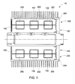
- Fig. 1 is a cross-sectional view of an exemplary rotary transformer 10.
- rotary transformer 10 includes a rotor assembly 100 and a stator assembly 200 within a housing 204.
- Rotor assembly 100 is positioned proximate stator assembly 200 for transfer of magnetic flux between rotor assembly 100 and stator assembly 200.
- stator assembly 200 is coupled to housing 204 in the exemplary embodiment, it should be understood that housing 204 may rotate about a stationary central stator of rotary transformer 10.
- stator assembly 200 includes stator windings 202 and rotor assembly 100 includes rotor windings 102 that are not in physical contact with stator windings 202.
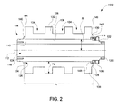
- Fig. 2 is a cross-sectional view of an exemplary rotor assembly 100, also referred to as an electrical assembly, that may be used with rotary transformer 10 (shown in Fig. 1 ).
- Fig. 3 is a perspective view of rotor assembly 100.
- Rotor assembly 100 includes a rotor core 104, at least one lamella 106, and a locking ring 108.
- lamella 106 is coupled to rotor core 104 and secured thereto by locking ring 108, as described in more detail herein. More specifically, lamella 106 is in contact with rotor core 104.
- Rotor core 104 also referred to as an assembly structure, includes a body 110 defining a longitudinal axis 112 of rotor assembly 100.
- a radius R 1 of rotor core 104 is substantially perpendicular to longitudinal axis 112.
- a first flange 114 and a second flange 116 extend from body 110. More specifically, first flange 114 is defined near a first end portion 118 of body 110, and second flange 116 is defined near an opposing second end portion 120 of body 110.
- a fastening portion 122 of body 110 is defined between second flange 116 and second end portion 120.
- fastening portion 122 is threaded to engage locking ring 108; however, fastening portion 122 can include any suitable mechanism for interlocking and/or engaging with locking ring 108 to secure lamella 106 to rotor core 104.
- First flange 114 defines includes a lip 124 and an annular channel 126 defined between body 110 and lip 124. More specifically, lip 124 extends outwardly about a circumference of body 110 and toward second end portion 120 to define annular channel 126.
- Second flange 116 includes an annular projection 128. More specifically, second flange 116 is substantially perpendicular to longitudinal axis 112 and extends circumferentially about body 110. As such, second flange 116 extends in a radial direction from body 110. Annular projection 128 extends from a peripheral end 130 of second flange 116 toward second end portion 120.
- lamella 106 is coupled to rotor core 104 at first flange 114 and second flange 116, as described in more detail below.
- Each lamella 106 of rotor assembly 100 is substantially similar. More specifically, each lamella 106 is configured to couple to rotor core 104 and to support at least one rotor winding 102. In the exemplary embodiment, each lamella 106 includes an outer end 132 configured to support rotor winding 102 thereon. As such, outer end 132 is configured to correspond to rotor winding 102 fir magnetic flux exchange. Rotor winding 102 is configured to wrap circumferentially about a plurality of lamellae 106 and/or rotor assembly 100.
- outer end 132 of lamella 106 defines three recesses 134 each configured to have a respective winding 102 positioned therein.
- outer end 132 includes any suitable configuration that enables rotor assembly 100 to function as described herein.
- Lamella 106 is shaped as a thin, generally rectangular plate in the exemplary embodiment. More specifically, lamella 106 has a length L 1 extending along rotor core body 110 substantially parallel to longitudinal axis 112 when lamella 106 is coupled to rotor core 104. Further, lamella 106 has a height H 1 extending from rotor core body 110 radially outward when lamella 106 is coupled to rotor core 104. As such, lamella length L 1 extends in an axial direction, and lamella height H 1 extends in a radial direction. In the exemplary embodiment, length L 1 is larger than height H 1 .
- a thickness T 1 of lamella 106 is measured tangentially to the circumference of rotor core 104. Thickness T 1 is substantially constant along height H 1 of lamella 106. Alternatively, thickness T 1 varies along at least a portion of height H 1 of lamella 106.
- rotor assembly 100 includes a plurality of lamellae 106 coupled about rotor core 104.
- Lamellae 106 are coupled in series circumferentially about rotor core 104, rather than being axially stacked.
- Lamellae 106 are adjacent each other and/or in contact at inner ends 136 of each lamella 106, and a gap 138 is defined between adjacent lamellae 106 along height H 1 .
- lamellae 106 are in contact other than at inner ends 136 of each lamella 106.
- a thickness of gap 138 increases from inner end 136 of lamella 106 toward outer end 132 of lamella 106.
- each lamella 106 has a thickness that increases from inner end 136 toward outer end 132 such that gap 138 has a substantially constant thickness and/or such that gap 138 is substantially eliminated.
- Each lamella 106 includes a foot 140 and a hook 142.
- Foot 140 is positioned at inner end 136 of lamella 106 and extends from a first end 144 of lamella 106.
- Hook 142 extends from a second end 146 of lamella 106.
- foot 140 is configured to be received within annular channel 126 to couple lamella 106 to rotor core 104.
- foot 140 has a shape that corresponds to a shape of annular channel 126.
- Hook 142 is configured to interlock with annular projection 128 to couple lamella 106 to rotor core 104. More specifically, hook 142 defines a notch 148 configured to receive annular projection 128 and/or second flange 116.
- Hook 142 is shaped to interlock with annular projection 128 when lamella 106 is coupled to rotor core 104.
- foot 140 and channel 126 are configured to secure lamella 106, radially and axially, to rotor core 104.
- hook 142 and annular projection 128 are configured to secure lamella 106, radially and axially, to rotor core 104.
- Locking ring 108 is configured to couple to rotor core 104 to secure at least one lamella 106 to rotor core 104. More specifically, in the exemplary embodiment, locking ring 108 is configured to engage and/or interlock with fastening portion 122 of rotor core 104. In a particular embodiment, locking ring 108 includes threads to enable locking ring 108 to be screwed onto threads of fastening portion 122. Alternatively, locking ring 108 includes any suitable configuration that enables locking ring 108 to function as described herein. In the exemplary embodiment, locking ring 108 is configured to force hook 142 against annular projection 128 to secure hook 142 against annular projection 128. By forcing hook 142 against annular projection 128, locking ring 108 also forces foot 140 into annular channel 126.
- lamella 106 is coupled to rotor core 104 at first flange 114 and second flange 116.
- lamella 106 has length L 1 substantially parallel to longitudinal axis 112 of rotor core 104 when coupled to rotor core 104.
- lamella 106 extends from first flange 114 to second flange 116 when coupled to rotor core 104.
- lamella 106 is positioned against rotor core body 110 at, for example, inner ends 136 of each lamella 106.
- Lamella 106 When lamella 106 is positioned against rotor core body 110, second flange 116 and/or annular projection 128 are positioned within notch 148. Lamella 106 is slid toward first end portion 118 to insert foot 140 into annular channel 126. As lamella 106 is slid, hook 142 and annular projection 128 interlock. In the exemplary embodiment, a plurality of lamellae 106 are coupled in series circumferentially to rotor core 104 by repeating the above-described steps. In a particular embodiment, lamellae 106 are laminated together.
- locking ring 108 is coupled to rotor core 104 to secure lamella 106 to rotor core 104 at first flange 114 and second flange 116. More specifically, locking ring 108 forces lamella 106 toward first end portion 118 of rotor core 104 to force hook 142 against annular projection 128 and to force foot 140 into annular channel 126 when locking ring 108 engages rotor core 104.
- locking ring 108 is threadably coupled to rotor core 104 to apply a force to hook 142, wherein the force has a direction from second flange 116 toward first flange 114.
- mating configurations such as foot 140 and channel 126 and/or hook 142 and annular projection 128, prevent axial and/or radial movement of lamella 106 with respect to rotor core 104.
- Rotor windings 102 are then coupled about a circumference of, and supported by, lamellae 106.
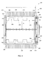
- Fig. 4 is a cross-sectional view of an exemplary stator assembly 200, also referred to as an electrical assembly, that may be used with rotary transformer 10 (shown in Fig. 1 ).
- Fig. 5 is a perspective view of stator assembly 200.
- Stator assembly 200 includes housing 204, at least one lamella 206, and a locking ring 208.
- lamella 206 is coupled to housing 204 and secured thereto by locking ring 208, as described in more detail herein. More specifically, lamella 206 is in contact with housing 204.
- Housing 204 also referred to as an assembly structure, includes a body 210 defining a longitudinal axis 212 of stator assembly 200.
- a radius R 2 of housing 204 is substantially perpendicular to longitudinal axis 212.
- a first flange 214 and a second flange 216 extend radially inward from body 210. More specifically, first flange 214 is defined near a first end portion 218 of body 210, and second flange 216 is defined near an opposing second end portion 220 of body 210.
- a fastening portion 222 of housing 204 is defined proximate second end portion 220. In the exemplary embodiment, fastening portion 222 is compressible against locking ring 208 to engage locking ring 208. More specifically, at least one screw 223 can be tightened against locking ring 208 to engage with locking ring 208. However, fastening portion 222 can include any suitable mechanism for interlocking and/or engaging with locking ring 208 to secure lamella 206 to housing 204.
- First flange 214 defines includes a lip 224 and an annular channel 226 defined between body 210 and lip 224. More specifically, lip 224 extends outwardly about a circumference of body 210 and toward second end portion 220 to define annular channel 226.
- Second flange 216 includes an annular projection 228. More specifically, second flange 216 is generally perpendicular to longitudinal axis 212 and extends circumferentially about body 210. As such, second flange 216 extends in a radial direction from body 210. Annular projection 228 extends from a peripheral end 230 of second flange 216 toward second end portion 220.
- lamella 206 is coupled to housing 204 at first flange 214 and second flange 216, as described in more detail below.
- each lamella 206 of stator assembly 200 is substantially similar. More specifically, each lamella 206 is configured to couple to housing 204 and to support at least one stator winding 202.
- each lamella 206 includes an inner end 232 configured to support stator winding 202 thereon.
- inner end 232 is configured to correspond to stator winding 202.
- Stator winding 202 is configured to wrap circumferentially about a plurality of lamellae 206 and/or stator assembly 200.
- inner end 232 of lamella 206 defines three recesses 234 each configured to have a respective winding 202 positioned therein.
- inner end 232 includes any suitable configuration that enables stator assembly 200 to function as described herein.
- Lamella 206 is shaped as a thin, generally rectangular plate in the exemplary embodiment. More specifically, lamella 206 has a length L 2 extending along rotor core body 210 substantially parallel to longitudinal axis 212 when lamella 206 is coupled to housing 204. Further, lamella 206 has a height H 2 extending from body 210 radially outward when lamella 206 is coupled to housing 204. As such, lamella length L 2 extends in an axial direction, and lamella height H 2 extends in a radial direction. In the exemplary embodiment, length L 2 is larger than height H 2 .
- a thickness T 2 of lamella 206 is measured tangentially to the circumference of housing 204. Thickness T 2 is substantially constant along height H 2 of lamella 206. Alternatively, thickness T 2 varies along at least a portion of height H 2 of lamella 206.
- stator assembly 200 includes a plurality of lamellae 206 coupled about housing 204.
- Lamellae 206 are coupled in series circumferentially about housing 204, rather than being axially stacked.
- Lamellae 206 are adjacent each other and/or in contact at outer ends 236 of each lamella 206, and a gap 238 is defined between adjacent lamellae 206 along height H 2 .
- lamellae 206 are in contact other than at outer ends 236 of each lamella 206.
- a thickness of gap 238 decreases from outer end 236 of lamella 206 toward inner end 232 of lamella 206.
- each lamella 206 has a thickness that decreases from outer end 236 toward inner end 232 such that gap 238 has a substantially constant thickness and/or such that gap 238 is substantially eliminated.
- Each lamella 206 includes a foot 240 and a hook 242.
- Foot 240 is positioned at outer end 236 of lamella 206 and extends from a first end 244 of lamella 206.
- Hook 242 extends from a second end 246 of lamella 206.
- foot 240 is configured to be received within annular channel 226 to couple lamella 206 to housing 204.
- foot 240 has a shape that corresponds to a shape of annular channel 226.
- Hook 242 is configured to interlock with annular projection 228 to couple lamella 206 to housing 204. More specifically, hook 242 defines a notch 248 configured to receive annular projection 228 and/or second flange 216.
- Hook 242 is shaped to interlock with annular projection 228 when lamella 206 is coupled to housing 204.
- foot 240 and channel 226 are configured to secure lamella 206, radially and axially, to housing 204.
- hook 242 and annular projection 228 are configured to secure lamella 206, radially and axially, to housing 204.
- Locking ring 208 is configured to couple to housing 204 to secure at least one lamella 206 to housing 204. More specifically, in the exemplary embodiment, locking ring 208 is configured to engage and/or interlock with fastening portion 222 of housing 204.
- fastening portion 222 is configured to be compressible using any suitable mechanism, such as screw 223. When fastening portion 222 is compressed, fastening portion 222 applies a force to locking ring 208, which pushes hook 242 against annular projection 228 to secure hook 242 against annular projection 228. By forcing hook 242 against annular projection 228, locking ring 208 and/or fastening portion 222 also forces foot 240 into annular channel 226.
- locking ring 208 and/or fastening portion 222 includes any suitable configuration that enables locking ring 208 to function as described herein.
- locking ring 208 and/or fastening portion 222 can include threads to enable locking ring 208 to be screwed onto fastening portion 222.
- At least one lamella 206 is coupled to housing 204 at first flange 214 and second flange 216.
- lamella 206 has length L 2 substantially parallel to longitudinal axis 212 of housing 204 when coupled to housing 204. As such, lamella 206 extends from first flange 214 to second flange 216 when coupled to housing 204.
- lamella 206 is positioned against body 210 at, for example, outer ends 236 of each lamella 206.
- Lamella 206 When lamella 206 is positioned against body 210, second flange 216 and/or annular projection 228 are positioned within notch 248. Lamella 206 is slid toward first end portion 218 to insert foot 240 into annular channel 226. As lamella 206 is slid, hook 242 and annular projection 228 interlock.
- a plurality of lamellae 206 are coupled in series circumferentially to housing 204 by repeating the above-described steps. In a particular embodiment, lamellae 206 are laminated together.
- locking ring 208 is coupled to housing 204 to secure lamella 206 to housing 204 at first flange 214 and second flange 216. More specifically, locking ring 208 forces lamella 206 toward first end portion 218 of housing 204 to force hook 242 against annular projection 228 and to force foot 240 into annular channel 226 when locking ring 208 engages with housing 204.
- fastening portion 222 is compressed against locking ring 208 to apply a force to hook 242, wherein the force has a direction from second flange 216 toward first flange 214.
- mating configurations such as foot 240 and channel 226 and/or hook 242 and annular projection 228, prevent axial and/or radial movement of lamella 206 with respect to housing 204.
- Stator windings 202 are then coupled about a circumference of, and supported by, lamellae 206.
- stator assembly 200 is provided as described above.
- Rotor assembly 100 as described above is also provided.
- Rotor assembly 100 is inserted into stator assembly 200 such that rotor windings 102 align with stator windings 202.
- a conventional stator assembly is provided, and rotor assembly 100 is inserted into the conventional stator assembly.
- a conventional rotor assembly is provided, and stator assembly 200 is coupled about the conventional rotor assembly.
Landscapes
- Engineering & Computer Science (AREA)
- Power Engineering (AREA)
- Manufacturing & Machinery (AREA)
- Iron Core Of Rotating Electric Machines (AREA)
Abstract
Description
- The embodiments described herein relate generally to an electrical assembly and, more particularly to an electrical assembly for use with a rotary transformer.
- At least one known rotor assembly for use in a rotary transformer includes a plurality of stacked plates, or laminations. The plates each include a central aperture defined therethrough for coupling the plates to a rotor core. More specifically, the rotor core is inserted through the central apertures such that the plates are stacked axially along the rotor core. Further, each plate is generally circular and includes cut-outs or other recesses defined along a circumferential end of the plate to support windings. At least some known windings extend substantially parallel to a longitudinal axis of the rotor core and are supported within the cut-outs or recesses defined by the stack of plates.
- In one aspect according to the present invention, an electrical assembly for use with a rotary transformer is provided. The electrical assembly includes a assembly structure having a first flange positioned proximate a first end portion of the assembly structure and a second flange positioned proximate a second end portion of the assembly structure. The electrical assembly further includes at least one lamella coupled to the assembly structure. The at least one lamella extends from the first flange to the second flange.
- In another aspect, a rotary transformer is provided. The rotary transformer includes a stator assembly and a rotor assembly positioned proximate the stator assembly. The stator assembly and/or the rotor assembly includes an electrical assembly having a assembly structure. The assembly structure includes a first flange positioned proximate a first end portion of the assembly structure and a second flange positioned proximate a second end portion of the assembly structure. The electrical assembly further includes at least one lamella coupled to the assembly structure. The at least one lamella extends from the first flange to the second flange.
- In yet another aspect, a method for making an electrical assembly including at least one lamella and a assembly structure is provided. The assembly structure has a first flange proximate a first end portion of the assembly structure and a second flange proximate a second end portion of the assembly structure. The method includes coupling the at least one lamella to the assembly structure at the first flange of the assembly structure and the second flange of the assembly structure. The at least one lamella extends from the first flange to the second flange. A locking ring is coupled to the assembly structure to secure the at least one lamella against the first flange and the second flange.
-
Figs. 1-5 show exemplary embodiments of the apparatus and methods described herein. -
Fig. 1 is a cross-sectional view of an exemplary rotary transformer. -
Fig. 2 is a cross-sectional view of an exemplary rotor assembly that may be used with the rotary transformer shown inFig. 1 . -
Fig. 3 is a perspective view of the rotor assembly shown inFig. 2 . -
Fig. 4 is a cross-sectional view of an exemplary stator assembly that may be used with the rotary transformer shown inFig. 1 . -
Fig. 5 is a perspective view of the stator assembly shown inFig. 4 . - Various of the embodiments described herein provide a rotor assembly and/or a stator assembly having axially-aligned lamellas, or plates, rather than axially-stacked plates. The rotor assembly and the stator assembly are each considered to be or include an electrical assembly. The herein-described lamellae are arrayed circumferentially about a rotor core. Each lamella includes fastening members, such as a foot and a hook, that enable each lamella to be coupled to the rotor core, without the rotor core being inserted through the lamella. When a stator assembly includes lamellae, the fastening members enable each lamella to be coupled to a housing. The rotor core and the housing are each considered to be an assembly structure. Each assembly structure includes flanges that engage with the fastening members of the lamella to facilitate coupling the lamella to the rotor core or housing. A locking ring secures the fastening members of the lamella to the flanges of the assembly structure. The rotor assembly and/or stator assembly described herein can be used within a rotary transformer.
-
Fig. 1 is a cross-sectional view of an exemplaryrotary transformer 10. In the exemplary embodiment,rotary transformer 10 includes arotor assembly 100 and astator assembly 200 within ahousing 204.Rotor assembly 100 is positionedproximate stator assembly 200 for transfer of magnetic flux betweenrotor assembly 100 andstator assembly 200. Althoughstator assembly 200 is coupled tohousing 204 in the exemplary embodiment, it should be understood thathousing 204 may rotate about a stationary central stator ofrotary transformer 10. In the exemplary embodiment,stator assembly 200 includesstator windings 202 androtor assembly 100 includesrotor windings 102 that are not in physical contact withstator windings 202. -
Fig. 2 is a cross-sectional view of anexemplary rotor assembly 100, also referred to as an electrical assembly, that may be used with rotary transformer 10 (shown inFig. 1 ).Fig. 3 is a perspective view ofrotor assembly 100.Rotor assembly 100 includes arotor core 104, at least onelamella 106, and alocking ring 108. In the exemplary embodiment,lamella 106 is coupled torotor core 104 and secured thereto bylocking ring 108, as described in more detail herein. More specifically,lamella 106 is in contact withrotor core 104.Rotor core 104, also referred to as an assembly structure, includes abody 110 defining alongitudinal axis 112 ofrotor assembly 100. A radius R1 ofrotor core 104 is substantially perpendicular tolongitudinal axis 112. Afirst flange 114 and asecond flange 116 extend frombody 110. More specifically,first flange 114 is defined near afirst end portion 118 ofbody 110, andsecond flange 116 is defined near an opposingsecond end portion 120 ofbody 110. Afastening portion 122 ofbody 110 is defined betweensecond flange 116 andsecond end portion 120. In the exemplary embodiment,fastening portion 122 is threaded to engagelocking ring 108; however, fasteningportion 122 can include any suitable mechanism for interlocking and/or engaging withlocking ring 108 to securelamella 106 torotor core 104. -
First flange 114 defines includes alip 124 and anannular channel 126 defined betweenbody 110 andlip 124. More specifically,lip 124 extends outwardly about a circumference ofbody 110 and towardsecond end portion 120 to defineannular channel 126.Second flange 116 includes anannular projection 128. More specifically,second flange 116 is substantially perpendicular tolongitudinal axis 112 and extends circumferentially aboutbody 110. As such,second flange 116 extends in a radial direction frombody 110.Annular projection 128 extends from aperipheral end 130 ofsecond flange 116 towardsecond end portion 120. In the exemplary embodiment,lamella 106 is coupled torotor core 104 atfirst flange 114 andsecond flange 116, as described in more detail below. - Each
lamella 106 ofrotor assembly 100 is substantially similar. More specifically, eachlamella 106 is configured to couple torotor core 104 and to support at least one rotor winding 102. In the exemplary embodiment, eachlamella 106 includes anouter end 132 configured to support rotor winding 102 thereon. As such,outer end 132 is configured to correspond to rotor winding 102 fir magnetic flux exchange. Rotor winding 102 is configured to wrap circumferentially about a plurality oflamellae 106 and/orrotor assembly 100. In a particular embodiment whenrotor assembly 100 includes threewindings 102,outer end 132 oflamella 106 defines threerecesses 134 each configured to have arespective winding 102 positioned therein. Alternatively,outer end 132 includes any suitable configuration that enablesrotor assembly 100 to function as described herein. -
Lamella 106 is shaped as a thin, generally rectangular plate in the exemplary embodiment. More specifically,lamella 106 has a length L1 extending alongrotor core body 110 substantially parallel tolongitudinal axis 112 whenlamella 106 is coupled torotor core 104. Further,lamella 106 has a height H1 extending fromrotor core body 110 radially outward whenlamella 106 is coupled torotor core 104. As such, lamella length L1 extends in an axial direction, and lamella height H1 extends in a radial direction. In the exemplary embodiment, length L1 is larger than height H1. A thickness T1 oflamella 106 is measured tangentially to the circumference ofrotor core 104. Thickness T1 is substantially constant along height H1 oflamella 106. Alternatively, thickness T1 varies along at least a portion of height H1 oflamella 106. - In the exemplary embodiment,
rotor assembly 100 includes a plurality oflamellae 106 coupled aboutrotor core 104.Lamellae 106 are coupled in series circumferentially aboutrotor core 104, rather than being axially stacked.Lamellae 106 are adjacent each other and/or in contact atinner ends 136 of eachlamella 106, and agap 138 is defined betweenadjacent lamellae 106 along height H1. Alternatively,lamellae 106 are in contact other than atinner ends 136 of eachlamella 106. In the exemplary embodiment, a thickness ofgap 138 increases frominner end 136 oflamella 106 towardouter end 132 oflamella 106. Alternatively, eachlamella 106 has a thickness that increases frominner end 136 towardouter end 132 such thatgap 138 has a substantially constant thickness and/or such thatgap 138 is substantially eliminated. - Each
lamella 106 includes afoot 140 and ahook 142.Foot 140 is positioned atinner end 136 oflamella 106 and extends from afirst end 144 oflamella 106.Hook 142 extends from asecond end 146 oflamella 106. In the exemplary embodiment,foot 140 is configured to be received withinannular channel 126 tocouple lamella 106 torotor core 104. As such,foot 140 has a shape that corresponds to a shape ofannular channel 126.Hook 142 is configured to interlock withannular projection 128 tocouple lamella 106 torotor core 104. More specifically,hook 142 defines anotch 148 configured to receiveannular projection 128 and/orsecond flange 116.Hook 142 is shaped to interlock withannular projection 128 whenlamella 106 is coupled torotor core 104. In the exemplary embodiment,foot 140 andchannel 126 are configured to securelamella 106, radially and axially, torotor core 104. Similarly,hook 142 andannular projection 128 are configured to securelamella 106, radially and axially, torotor core 104. - Locking
ring 108 is configured to couple torotor core 104 to secure at least onelamella 106 torotor core 104. More specifically, in the exemplary embodiment, lockingring 108 is configured to engage and/or interlock withfastening portion 122 ofrotor core 104. In a particular embodiment, lockingring 108 includes threads to enable lockingring 108 to be screwed onto threads offastening portion 122. Alternatively, lockingring 108 includes any suitable configuration that enables lockingring 108 to function as described herein. In the exemplary embodiment, lockingring 108 is configured to forcehook 142 againstannular projection 128 to securehook 142 againstannular projection 128. By forcinghook 142 againstannular projection 128, lockingring 108 also forcesfoot 140 intoannular channel 126. - Referring to
Figs. 2 and3 , to make, assemble, and/or otherwise manufacturerotor assembly 100, at least onelamella 106 is coupled torotor core 104 atfirst flange 114 andsecond flange 116. As described above,lamella 106 has length L1 substantially parallel tolongitudinal axis 112 ofrotor core 104 when coupled torotor core 104. As such,lamella 106 extends fromfirst flange 114 tosecond flange 116 when coupled torotor core 104. In the exemplary embodiment,lamella 106 is positioned againstrotor core body 110 at, for example, inner ends 136 of eachlamella 106. When lamella 106 is positioned againstrotor core body 110,second flange 116 and/orannular projection 128 are positioned withinnotch 148.Lamella 106 is slid towardfirst end portion 118 to insertfoot 140 intoannular channel 126. Aslamella 106 is slid,hook 142 andannular projection 128 interlock. In the exemplary embodiment, a plurality oflamellae 106 are coupled in series circumferentially torotor core 104 by repeating the above-described steps. In a particular embodiment,lamellae 106 are laminated together. - When at least one
lamella 106 is coupled torotor core 104, lockingring 108 is coupled torotor core 104 to securelamella 106 torotor core 104 atfirst flange 114 andsecond flange 116. More specifically, lockingring 108 forces lamella 106 towardfirst end portion 118 ofrotor core 104 to forcehook 142 againstannular projection 128 and to forcefoot 140 intoannular channel 126 when lockingring 108 engagesrotor core 104. In the exemplary embodiment, lockingring 108 is threadably coupled torotor core 104 to apply a force to hook 142, wherein the force has a direction fromsecond flange 116 towardfirst flange 114. When lockingring 108 secureslamella 106 torotor core 104, mating configurations, such asfoot 140 andchannel 126 and/orhook 142 andannular projection 128, prevent axial and/or radial movement oflamella 106 with respect torotor core 104.Rotor windings 102 are then coupled about a circumference of, and supported by,lamellae 106. -
Fig. 4 is a cross-sectional view of anexemplary stator assembly 200, also referred to as an electrical assembly, that may be used with rotary transformer 10 (shown inFig. 1 ).Fig. 5 is a perspective view ofstator assembly 200.Stator assembly 200 includeshousing 204, at least onelamella 206, and alocking ring 208. In the exemplary embodiment,lamella 206 is coupled tohousing 204 and secured thereto by lockingring 208, as described in more detail herein. More specifically,lamella 206 is in contact withhousing 204.Housing 204, also referred to as an assembly structure, includes abody 210 defining alongitudinal axis 212 ofstator assembly 200. A radius R2 ofhousing 204 is substantially perpendicular tolongitudinal axis 212. Afirst flange 214 and asecond flange 216 extend radially inward frombody 210. More specifically,first flange 214 is defined near afirst end portion 218 ofbody 210, andsecond flange 216 is defined near an opposingsecond end portion 220 ofbody 210. Afastening portion 222 ofhousing 204 is defined proximatesecond end portion 220. In the exemplary embodiment,fastening portion 222 is compressible against lockingring 208 to engage lockingring 208. More specifically, at least onescrew 223 can be tightened against lockingring 208 to engage with lockingring 208. However,fastening portion 222 can include any suitable mechanism for interlocking and/or engaging with lockingring 208 to securelamella 206 tohousing 204. -
First flange 214 defines includes alip 224 and anannular channel 226 defined betweenbody 210 andlip 224. More specifically,lip 224 extends outwardly about a circumference ofbody 210 and towardsecond end portion 220 to defineannular channel 226.Second flange 216 includes anannular projection 228. More specifically,second flange 216 is generally perpendicular tolongitudinal axis 212 and extends circumferentially aboutbody 210. As such,second flange 216 extends in a radial direction frombody 210.Annular projection 228 extends from aperipheral end 230 ofsecond flange 216 towardsecond end portion 220. In the exemplary embodiment,lamella 206 is coupled tohousing 204 atfirst flange 214 andsecond flange 216, as described in more detail below. - Each
lamella 206 ofstator assembly 200 is substantially similar. More specifically, eachlamella 206 is configured to couple tohousing 204 and to support at least one stator winding 202. In the exemplary embodiment, eachlamella 206 includes aninner end 232 configured to support stator winding 202 thereon. As such,inner end 232 is configured to correspond to stator winding 202. Stator winding 202 is configured to wrap circumferentially about a plurality oflamellae 206 and/orstator assembly 200. In a particular embodiment whenstator assembly 200 includes threewindings 202,inner end 232 oflamella 206 defines threerecesses 234 each configured to have a respective winding 202 positioned therein. Alternatively,inner end 232 includes any suitable configuration that enablesstator assembly 200 to function as described herein. -
Lamella 206 is shaped as a thin, generally rectangular plate in the exemplary embodiment. More specifically,lamella 206 has a length L2 extending alongrotor core body 210 substantially parallel tolongitudinal axis 212 whenlamella 206 is coupled tohousing 204. Further,lamella 206 has a height H2 extending frombody 210 radially outward whenlamella 206 is coupled tohousing 204. As such, lamella length L2 extends in an axial direction, and lamella height H2 extends in a radial direction. In the exemplary embodiment, length L2 is larger than height H2. A thickness T2 oflamella 206 is measured tangentially to the circumference ofhousing 204. Thickness T2 is substantially constant along height H2 oflamella 206. Alternatively, thickness T2 varies along at least a portion of height H2 oflamella 206. - In the exemplary embodiment,
stator assembly 200 includes a plurality oflamellae 206 coupled abouthousing 204.Lamellae 206 are coupled in series circumferentially abouthousing 204, rather than being axially stacked.Lamellae 206 are adjacent each other and/or in contact atouter ends 236 of eachlamella 206, and agap 238 is defined betweenadjacent lamellae 206 along height H2. Alternatively,lamellae 206 are in contact other than atouter ends 236 of eachlamella 206. In the exemplary embodiment, a thickness ofgap 238 decreases fromouter end 236 oflamella 206 towardinner end 232 oflamella 206. Alternatively, eachlamella 206 has a thickness that decreases fromouter end 236 towardinner end 232 such thatgap 238 has a substantially constant thickness and/or such thatgap 238 is substantially eliminated. - Each
lamella 206 includes afoot 240 and ahook 242.Foot 240 is positioned atouter end 236 oflamella 206 and extends from afirst end 244 oflamella 206.Hook 242 extends from asecond end 246 oflamella 206. In the exemplary embodiment,foot 240 is configured to be received withinannular channel 226 tocouple lamella 206 tohousing 204. As such,foot 240 has a shape that corresponds to a shape ofannular channel 226.Hook 242 is configured to interlock withannular projection 228 tocouple lamella 206 tohousing 204. More specifically,hook 242 defines anotch 248 configured to receiveannular projection 228 and/orsecond flange 216.Hook 242 is shaped to interlock withannular projection 228 whenlamella 206 is coupled tohousing 204. In the exemplary embodiment,foot 240 andchannel 226 are configured to securelamella 206, radially and axially, tohousing 204. Similarly,hook 242 andannular projection 228 are configured to securelamella 206, radially and axially, tohousing 204. - Locking
ring 208 is configured to couple tohousing 204 to secure at least onelamella 206 tohousing 204. More specifically, in the exemplary embodiment, lockingring 208 is configured to engage and/or interlock withfastening portion 222 ofhousing 204. In a particular embodiment,fastening portion 222 is configured to be compressible using any suitable mechanism, such asscrew 223. When fasteningportion 222 is compressed,fastening portion 222 applies a force to lockingring 208, which pusheshook 242 againstannular projection 228 to securehook 242 againstannular projection 228. By forcinghook 242 againstannular projection 228, lockingring 208 and/orfastening portion 222 also forcesfoot 240 intoannular channel 226. Alternatively, lockingring 208 and/orfastening portion 222 includes any suitable configuration that enables lockingring 208 to function as described herein. For example, lockingring 208 and/orfastening portion 222 can include threads to enable lockingring 208 to be screwed ontofastening portion 222. - Referring to
Figs. 4 and5 , to make, assemble, and/or otherwise manufacturestator assembly 200, at least onelamella 206 is coupled tohousing 204 atfirst flange 214 andsecond flange 216. As described above,lamella 206 has length L2 substantially parallel tolongitudinal axis 212 ofhousing 204 when coupled tohousing 204. As such,lamella 206 extends fromfirst flange 214 tosecond flange 216 when coupled tohousing 204. In the exemplary embodiment,lamella 206 is positioned againstbody 210 at, for example, outer ends 236 of eachlamella 206. When lamella 206 is positioned againstbody 210,second flange 216 and/orannular projection 228 are positioned withinnotch 248.Lamella 206 is slid towardfirst end portion 218 to insertfoot 240 intoannular channel 226. Aslamella 206 is slid,hook 242 andannular projection 228 interlock. In the exemplary embodiment, a plurality oflamellae 206 are coupled in series circumferentially tohousing 204 by repeating the above-described steps. In a particular embodiment,lamellae 206 are laminated together. - When at least one
lamella 206 is coupled tohousing 204, lockingring 208 is coupled tohousing 204 to securelamella 206 tohousing 204 atfirst flange 214 andsecond flange 216. More specifically, lockingring 208 forces lamella 206 towardfirst end portion 218 ofhousing 204 to forcehook 242 againstannular projection 228 and to forcefoot 240 intoannular channel 226 when lockingring 208 engages withhousing 204. In the exemplary embodiment,fastening portion 222 is compressed against lockingring 208 to apply a force to hook 242, wherein the force has a direction fromsecond flange 216 towardfirst flange 214. When lockingring 208 secureslamella 206 tohousing 204, mating configurations, such asfoot 240 andchannel 226 and/orhook 242 andannular projection 228, prevent axial and/or radial movement oflamella 206 with respect tohousing 204.Stator windings 202 are then coupled about a circumference of, and supported by,lamellae 206. - Referring to
Figs. 1-5 , to make, assemble, and/or otherwise manufacturerotary transformer 10,stator assembly 200 is provided as described above.Rotor assembly 100 as described above is also provided.Rotor assembly 100 is inserted intostator assembly 200 such thatrotor windings 102 align withstator windings 202. Alternatively, a conventional stator assembly is provided, androtor assembly 100 is inserted into the conventional stator assembly. In an alternative embodiment, a conventional rotor assembly is provided, andstator assembly 200 is coupled about the conventional rotor assembly. - Exemplary embodiments of an electrical assembly and method for making the same are described above in detail. The methods and apparatus are not limited to the specific embodiments described herein, but rather, components of systems and/or steps of the methods may be utilized independently and separately from other components and/or steps described herein.
- Although specific features of various embodiments of the invention may be shown in some drawings and not in others, this is for convenience only. In accordance with the principles of the invention, any feature of a drawing may be referenced and/or claimed in combination with any feature of any other drawing.
- This written description uses examples to disclose the invention, including the preferred mode, and also to enable any person skilled in the art to practice the invention, including making and using any devices or systems and performing any incorporated methods. The patentable scope of the invention is defined by the claims, and may include other examples that occur to those skilled in the art. Such other examples are intended to be within the scope of the claims if they have structural elements that do not differ from the literal language of the claims, or if they include equivalent structural elements with insubstantial differences from the literal language of the claims.
- Various aspects and embodiments of the present invention are defined by the following numbered clauses:
- 1. An electrical assembly for use with a rotary transformer, said electrical assembly comprising:
- an assembly structure comprising a first flange positioned proximate a first end portion of said assembly structure and a second flange positioned proximate a second end portion of said assembly structure; and
- at least one lamella coupled to said assembly structure, said at least one lamella extending from said first flange to said second flange.
- 2. An electrical assembly in accordance with clause 1 further comprising a locking ring configured to couple to said assembly structure to secure said at least one lamella to said assembly structure.
- 3. An electrical assembly in accordance with any preceding clause, wherein:
- said first flange defines an annular channel; and
- said second flange includes an annular projection, said at least one lamella coupled to said assembly structure at said first flange and said second flange.
- 4. An electrical assembly in accordance with any preceding clause, wherein said at least one lamella comprises a foot configured to be received within said annular channel to couple said at least one lamella to said assembly structure.
- 5. An electrical assembly in accordance with any preceding clause, wherein said at least one lamella comprises a hook configured to interlock with said annular projection to couple said at least one lamella to said assembly structure.
- 6. An electrical assembly in accordance with any preceding clause, further comprising a locking ring coupled to said assembly structure to secure said hook against said annular projection.
- 7. An electrical assembly in accordance with any preceding clause, wherein said at least one lamella comprises a plurality of lamellae coupled to said assembly structure in series about a circumference of said assembly structure.
- 8. An electrical assembly in accordance with any preceding clause, wherein said assembly structure has a longitudinal axis and a radius substantially perpendicular to the longitudinal axis, and said at least one lamella having a length that is substantially parallel to the longitudinal axis and a height that extends in a radial direction, wherein the length is larger than the height.
- 9. A rotary transformer comprising:
- a stator assembly; and
- a rotor assembly positioned proximate said stator assembly, at least one of said stator assembly and said rotor assembly comprising an electrical assembly comprising:
- an assembly structure comprising a first flange positioned proximate a first end portion of said assembly structure and a second flange positioned proximate a second end portion of said assembly structure; and
- at least one lamella coupled to said assembly structure, said at least one lamella extending from said first flange to said second flange.
- 10. A rotary transformer in accordance with any preceding clause, wherein said electrical assembly further comprises a locking ring configured to couple to said assembly structure to secure said at least one lamella to said assembly structure.
- 11. A rotary transformer in accordance with any preceding clause, wherein:
- said first flange defines an annular channel; and
- said second flange includes an annular projection, said at least one lamella coupled to said assembly structure at said first flange and said second flange.
- 12. A rotary transformer in accordance with any preceding clause, wherein said at least one lamella comprises a foot configured to be received within said annular channel to couple said at least one lamella to said assembly structure.
- 13. A rotary transformer in accordance with any preceding clause, wherein said at least one lamella comprises a hook configured to interlock with said annular projection to couple said at least one lamella to said assembly structure.
- 14. A rotary transformer in accordance with any preceding clause, wherein said electrical assembly further comprises a locking ring coupled to said assembly structure to secure said hook against said annular projection.
- 15. A rotary transformer in accordance with any preceding clause, wherein said at least one lamella comprises a plurality of lamellae coupled to said assembly structure in series about a circumference of said assembly structure.
- 16. A method for making an electrical assembly including at least one lamella and an assembly structure having a first flange proximate a first end portion of the assembly structure and a second flange proximate a second end portion of the assembly structure, said method comprising:
- coupling the at least one lamella to the assembly structure at the first flange of the assembly structure and the second flange of the assembly structure, the at least one lamella extending from the first flange to the second flange; and
- coupling a locking ring to the assembly structure to secure the at least one lamella against the first flange and the second flange.
- 17. A method in accordance with any preceding clause, wherein the first flange defines an annular channel, the second flange includes an annular projection, and the at least one lamella includes a foot and a hook, the method further comprising:
- inserting the foot of the least one lamella into the annular channel;
- interlocking the hook of the at least one lamella with the annular projection; and
- coupling the locking ring to the assembly structure to secure the hook against the annular projection.
- 18. A method in accordance with any preceding clause, wherein coupling the locking ring to the rotor core to secure the hook against the annular projection further comprises threadably coupling the locking ring to the assembly structure to apply a force to the hook, the force having a direction from the second flange toward the first flange.
- 19. A method in accordance with any preceding clause, wherein coupling the at least one lamella to the assembly structure further comprises coupling a plurality of lamellae about a circumference of the assembly structure, the plurality of lamellae secured to the assembly structure by the locking ring.
- 20. A method in accordance with any preceding clause, further comprising coupling windings about the plurality of lamellae.
Claims (15)
- An electrical assembly for use with a rotary transformer (10), said electrical assembly comprising:an assembly structure comprising a first flange (114,214) positioned proximate a first end portion (118,218) of said assembly structure and a second flange (116,216) positioned proximate a second end portion (120,220) of said assembly structure; andat least one lamella (106,206) coupled to said assembly structure, said at least one lamella extending from said first flange to said second flange.
- An electrical assembly in accordance with Claim 1 further comprising a locking ring (108,208) configured to couple to said assembly structure to secure said at least one lamella (106,206) to said assembly structure.
- An electrical assembly in accordance with any preceding Claim, wherein:said first flange (114,214) defines an annular channel (126,226); andsaid second flange (116,216) includes an annular projection (128,228), said at least one lamella (106,206) coupled to said assembly structure at said first flange and said second flange.
- An electrical assembly in accordance with any preceding Claim, wherein said at least one lamella (106,206) comprises a foot (142,242) configured to be received within said annular channel (126,226) to couple said at least one lamella to said assembly structure.
- An electrical assembly in accordance with any preceding Claim, wherein said at least one lamella (106,206) comprises a hook (142,242) configured to interlock with said annular projection (128,228) to couple said at least one lamella to said assembly structure.
- An electrical assembly in accordance with any preceding Claim, further comprising a locking ring (108,208) coupled to said assembly structure to secure said hook (142,242) against said annular projection (128,228).
- An electrical assembly in accordance with any preceding Claim, wherein said at least one lamella (106,206) comprises a plurality of lamellae coupled to said assembly structure in series about a circumference of said assembly structure.
- An electrical assembly in accordance with any preceding Claim, wherein said assembly structure has a longitudinal axis (112,212) and a radius substantially perpendicular to the longitudinal axis, and said at least one lamella (106,206) having a length that is substantially parallel to the longitudinal axis and a height that extends in a radial direction, wherein the length is larger than the height.
- A rotary transformer comprising:a stator assembly (200); anda rotor assembly (100) positioned proximate said stator assembly, at least one of said stator assembly and said rotor assembly comprising an electrical assembly comprising:an assembly structure comprising a first flange (114) positioned proximate a first end portion (118,218) of said assembly structure and a second flange (116,216) positioned proximate a second end portion (120,220) of said assembly structure; andat least one lamella (106,206) coupled to said assembly structure, said at least one lamella extending from said first flange to said second flange.
- A rotary transformer in accordance with Claim 9, wherein:said electrical assembly further comprises a locking ring (108,208) configured to couple to said assembly structure to secure said at least one lamella (106,206) to said assembly structure;said at least one lamella comprises a hook (142,242); andsaid second flange (116,216) comprises an annular projection, said hook configured to interlock with said annular projection (128,228), and said locking ring configured to secure said hook against said annular projection.
- A rotary transformer in accordance with Claim 9 or Claim 10, wherein:said first flange (114,214) defines an annular channel (126,226);said second flange (116,216) comprises an annular projection (128,228); andsaid at least one lamella (106,206) comprises a foot (140,240) configured to be received within said annular channel to couple said at least one lamella to said assembly structure at said first flange and said second flange.
- A method for making an electrical assembly including at least one lamella (106,206) and an assembly structure having a first flange (114,214) proximate a first end portion (118,218) of the assembly structure and a second flange (116,216) proximate a second end portion (120,220) of the assembly structure, said method comprising:coupling the at least one lamella to the assembly structure at the first flange of the assembly structure and the second flange of the assembly structure, the at least one lamella extending from the first flange to the second flange; andcoupling a locking ring (108,208) to the assembly structure to secure the at least one lamella against the first flange and the second flange.
- A method in accordance with Claim 12, wherein the first flange (114,214) defines an annular channel (126,226), the second flange includes an annular projection (128,228), and the at least one lamella (106,206) includes a foot (140,240) and a hook (142,242), the method further comprising:inserting the foot of the least one lamella into the annular channel;interlocking the hook of the at least one lamella with the annular projection; andcoupling the locking ring (108,208) to the assembly structure to secure the hook against the annular projection.
- A method in accordance with Claim 12 or Claim 13, wherein coupling the locking ring (108,208) to the rotor core (104,204) to secure the hook (142,242) against the annular projection (128,228) further comprises threadably coupling the locking ring (108,208) to the assembly structure to apply a force to the hook, the force having a direction from the second flange toward the first flange.
- A method in accordance with any of Claims 12 to 14, wherein coupling the at least one lamella (106,206) to the assembly structure further comprises coupling a plurality of lamellae about a circumference of the assembly structure, the plurality of lamellae secured to the assembly structure by the locking ring (108,208).
Applications Claiming Priority (1)
| Application Number | Priority Date | Filing Date | Title |
|---|---|---|---|
| US12/974,494 US8390419B2 (en) | 2010-12-21 | 2010-12-21 | Electrical assembly and method for making the same |
Publications (1)
| Publication Number | Publication Date |
|---|---|
| EP2469546A1 true EP2469546A1 (en) | 2012-06-27 |
Family
ID=44559420
Family Applications (1)
| Application Number | Title | Priority Date | Filing Date |
|---|---|---|---|
| EP20110193667 Withdrawn EP2469546A1 (en) | 2010-12-21 | 2011-12-15 | Electrical assembly and method for making the same |
Country Status (3)
| Country | Link |
|---|---|
| US (1) | US8390419B2 (en) |
| EP (1) | EP2469546A1 (en) |
| CN (1) | CN102543408B (en) |
Families Citing this family (2)
| Publication number | Priority date | Publication date | Assignee | Title |
|---|---|---|---|---|
| US20140340185A1 (en) * | 2011-08-16 | 2014-11-20 | Pierce Verleur | Rotary Connection for Electric Power Transmission |
| US9640315B2 (en) * | 2013-05-13 | 2017-05-02 | General Electric Company | Low stray-loss transformers and methods of assembling the same |
Citations (4)
| Publication number | Priority date | Publication date | Assignee | Title |
|---|---|---|---|---|
| US3502914A (en) * | 1969-01-16 | 1970-03-24 | Cambridge Thermionic Corp | Stepping motor rotor and stator with plastic embedded laminated pole pieces and method of making |
| US20030080634A1 (en) * | 2001-10-26 | 2003-05-01 | Kye-Si Kwon | Reciprocating motor |
| US20030102725A1 (en) * | 2001-05-24 | 2003-06-05 | Si-Hang Jeon | Stator for reciprocating motor |
| EP1580427A2 (en) * | 2004-03-25 | 2005-09-28 | Lg Electronics Inc. | Structure for fixing motor stator of reciprocating compressor |
Family Cites Families (11)
| Publication number | Priority date | Publication date | Assignee | Title |
|---|---|---|---|---|
| US3990141A (en) * | 1975-03-03 | 1976-11-09 | General Electric Company | Methods of making dynamoelectric machine structures |
| JPH0332333A (en) * | 1989-06-26 | 1991-02-12 | Fanuc Ltd | Radial type rotor structure |
| JP2986315B2 (en) * | 1993-08-31 | 1999-12-06 | キヤノン株式会社 | Method of manufacturing rotary transformer in magnetic recording / reproducing apparatus |
| DE69402707T2 (en) * | 1994-10-05 | 1997-09-11 | Denso Corp | Electric rotating machine and method of manufacturing the same |
| JPH0946983A (en) * | 1995-05-23 | 1997-02-14 | Fanuc Ltd | Finishing method for frame of electric motor and electric motor processed by this method |
| US5945748A (en) * | 1997-04-29 | 1999-08-31 | Lg Electronics, Inc. | Linear motor structure for linear compressor |
| US6133669A (en) * | 1997-12-31 | 2000-10-17 | Tupper; Christopher N. | Low-loss magnet core for high frequency claw-pole-type alternator |
| EP1005052B1 (en) * | 1998-06-10 | 2012-11-28 | The Furukawa Electric Co., Ltd. | Method of assembling isolation transformer |
| WO2002027898A1 (en) * | 2000-09-26 | 2002-04-04 | Matsushita Electric Industrial Co., Ltd. | Linear actuator |
| DE10344055A1 (en) * | 2003-09-23 | 2005-04-21 | Siemens Ag | Inductive rotary transformer |
| US20100148505A1 (en) * | 2008-12-16 | 2010-06-17 | Dunlap Gregory M | Contact-less power and signal transmission device for a high power level transformer |
-
2010
- 2010-12-21 US US12/974,494 patent/US8390419B2/en not_active Expired - Fee Related
-
2011
- 2011-12-15 EP EP20110193667 patent/EP2469546A1/en not_active Withdrawn
- 2011-12-21 CN CN201110452840.8A patent/CN102543408B/en active Active
Patent Citations (4)
| Publication number | Priority date | Publication date | Assignee | Title |
|---|---|---|---|---|
| US3502914A (en) * | 1969-01-16 | 1970-03-24 | Cambridge Thermionic Corp | Stepping motor rotor and stator with plastic embedded laminated pole pieces and method of making |
| US20030102725A1 (en) * | 2001-05-24 | 2003-06-05 | Si-Hang Jeon | Stator for reciprocating motor |
| US20030080634A1 (en) * | 2001-10-26 | 2003-05-01 | Kye-Si Kwon | Reciprocating motor |
| EP1580427A2 (en) * | 2004-03-25 | 2005-09-28 | Lg Electronics Inc. | Structure for fixing motor stator of reciprocating compressor |
Also Published As
| Publication number | Publication date |
|---|---|
| CN102543408A (en) | 2012-07-04 |
| US20110221555A1 (en) | 2011-09-15 |
| US8390419B2 (en) | 2013-03-05 |
| CN102543408B (en) | 2016-09-21 |
Similar Documents
| Publication | Publication Date | Title |
|---|---|---|
| CN107005135B (en) | Stator manufacturing method and coil | |
| CN106416022A (en) | Stator assembly method and stator assembly device | |
| US11411447B2 (en) | Axial gap motor | |
| US9923421B2 (en) | Rotor structure for motor | |
| US10818427B2 (en) | Stator assembly including a bobbin having an extension tab and a retention rib | |
| KR101961142B1 (en) | Electric motor and manufacturing method for rotor thereof | |
| US20170310176A1 (en) | Rotor, method of manufacturing rotor, and rotary electric machine including rotor | |
| CN108521179A (en) | Stator module, motor and compressor | |
| US20190013136A1 (en) | Reactor and method for production of core body | |
| US8390419B2 (en) | Electrical assembly and method for making the same | |
| US10643779B2 (en) | Reactor having outer peripheral iron core and iron core coils | |
| US20040252001A1 (en) | Insulator for armature | |
| JP4834753B2 (en) | Stator manufacturing method and motor | |
| US20260058504A1 (en) | Stator core | |
| US20140028135A1 (en) | Axial bearing device having increased iron filling | |
| GB2328892A (en) | Winding method and winding apparatus for producing stators for electric motors | |
| CN107834721A (en) | Motor stator and there is its motor | |
| US11936263B2 (en) | Stator assembly and stator for motor | |
| JP2012205489A (en) | Stator of rotary electric machine and method for manufacturing the same | |
| DK2463872T3 (en) | Electrical device for use in a rotary transformer and method of manufacturing it | |
| JP2024031260A (en) | Stator manufacturing method | |
| JP2015162975A (en) | Stator and inner rotor type motor | |
| JP2011004456A (en) | Motor | |
| CN107482803B (en) | Stator module, motor and compressor | |
| KR20110118244A (en) | Stator for motor and motor with same |
Legal Events
| Date | Code | Title | Description |
|---|---|---|---|
| AK | Designated contracting states |
Kind code of ref document: A1 Designated state(s): AL AT BE BG CH CY CZ DE DK EE ES FI FR GB GR HR HU IE IS IT LI LT LU LV MC MK MT NL NO PL PT RO RS SE SI SK SM TR |
|
| AX | Request for extension of the european patent |
Extension state: BA ME |
|
| PUAI | Public reference made under article 153(3) epc to a published international application that has entered the european phase |
Free format text: ORIGINAL CODE: 0009012 |
|
| 17P | Request for examination filed |
Effective date: 20130102 |
|
| GRAP | Despatch of communication of intention to grant a patent |
Free format text: ORIGINAL CODE: EPIDOSNIGR1 |
|
| INTG | Intention to grant announced |
Effective date: 20150417 |
|
| RIN1 | Information on inventor provided before grant (corrected) |
Inventor name: HEMMELMANN, JAN Inventor name: FISENI, ALEXANDER FELIX |
|
| STAA | Information on the status of an ep patent application or granted ep patent |
Free format text: STATUS: THE APPLICATION IS DEEMED TO BE WITHDRAWN |
|
| 18D | Application deemed to be withdrawn |
Effective date: 20150828 |