EP2469346A2 - Fusing device and image forming apparatus having the same - Google Patents
Fusing device and image forming apparatus having the same Download PDFInfo
- Publication number
- EP2469346A2 EP2469346A2 EP20110189957 EP11189957A EP2469346A2 EP 2469346 A2 EP2469346 A2 EP 2469346A2 EP 20110189957 EP20110189957 EP 20110189957 EP 11189957 A EP11189957 A EP 11189957A EP 2469346 A2 EP2469346 A2 EP 2469346A2
- Authority
- EP
- European Patent Office
- Prior art keywords
- fusing
- belt
- guide
- fusing belt
- lubricant
- Prior art date
- Legal status (The legal status is an assumption and is not a legal conclusion. Google has not performed a legal analysis and makes no representation as to the accuracy of the status listed.)
- Granted
Links
Images



Classifications
-
- G—PHYSICS
- G03—PHOTOGRAPHY; CINEMATOGRAPHY; ANALOGOUS TECHNIQUES USING WAVES OTHER THAN OPTICAL WAVES; ELECTROGRAPHY; HOLOGRAPHY
- G03G—ELECTROGRAPHY; ELECTROPHOTOGRAPHY; MAGNETOGRAPHY
- G03G15/00—Apparatus for electrographic processes using a charge pattern
- G03G15/20—Apparatus for electrographic processes using a charge pattern for fixing, e.g. by using heat
- G03G15/2003—Apparatus for electrographic processes using a charge pattern for fixing, e.g. by using heat using heat
- G03G15/2014—Apparatus for electrographic processes using a charge pattern for fixing, e.g. by using heat using heat using contact heat
- G03G15/2017—Structural details of the fixing unit in general, e.g. cooling means, heat shielding means
- G03G15/2025—Structural details of the fixing unit in general, e.g. cooling means, heat shielding means with special means for lubricating and/or cleaning the fixing unit, e.g. applying offset preventing fluid
-
- G—PHYSICS
- G03—PHOTOGRAPHY; CINEMATOGRAPHY; ANALOGOUS TECHNIQUES USING WAVES OTHER THAN OPTICAL WAVES; ELECTROGRAPHY; HOLOGRAPHY
- G03G—ELECTROGRAPHY; ELECTROPHOTOGRAPHY; MAGNETOGRAPHY
- G03G15/00—Apparatus for electrographic processes using a charge pattern
- G03G15/20—Apparatus for electrographic processes using a charge pattern for fixing, e.g. by using heat
- G03G15/2003—Apparatus for electrographic processes using a charge pattern for fixing, e.g. by using heat using heat
- G03G15/2014—Apparatus for electrographic processes using a charge pattern for fixing, e.g. by using heat using heat using contact heat
- G03G15/2017—Structural details of the fixing unit in general, e.g. cooling means, heat shielding means
- G03G15/2028—Structural details of the fixing unit in general, e.g. cooling means, heat shielding means with means for handling the copy material in the fixing nip, e.g. introduction guides, stripping means
-
- G—PHYSICS
- G03—PHOTOGRAPHY; CINEMATOGRAPHY; ANALOGOUS TECHNIQUES USING WAVES OTHER THAN OPTICAL WAVES; ELECTROGRAPHY; HOLOGRAPHY
- G03G—ELECTROGRAPHY; ELECTROPHOTOGRAPHY; MAGNETOGRAPHY
- G03G2215/00—Apparatus for electrophotographic processes
- G03G2215/20—Details of the fixing device or porcess
- G03G2215/2003—Structural features of the fixing device
- G03G2215/2016—Heating belt
- G03G2215/2035—Heating belt the fixing nip having a stationary belt support member opposing a pressure member
-
- G—PHYSICS
- G03—PHOTOGRAPHY; CINEMATOGRAPHY; ANALOGOUS TECHNIQUES USING WAVES OTHER THAN OPTICAL WAVES; ELECTROGRAPHY; HOLOGRAPHY
- G03G—ELECTROGRAPHY; ELECTROPHOTOGRAPHY; MAGNETOGRAPHY
- G03G2215/00—Apparatus for electrophotographic processes
- G03G2215/20—Details of the fixing device or porcess
- G03G2215/2003—Structural features of the fixing device
- G03G2215/2016—Heating belt
- G03G2215/2035—Heating belt the fixing nip having a stationary belt support member opposing a pressure member
- G03G2215/2038—Heating belt the fixing nip having a stationary belt support member opposing a pressure member the belt further entrained around one or more rotating belt support members
Definitions
- Embodiments relate to a fusing device to fix an image to a recording medium and an image forming apparatus having the same.
- An image forming apparatus is designed to print an image on a recording medium.
- Examples of image forming apparatuses include printers, copiers, fax machines, and devices combining functions thereof.
- an electro-photographic image forming apparatus a photoconductor, which has been charged with a predetermined electric potential, is exposed to light such that an electrostatic latent image is formed on a surface of the photoconductor. Thereafter, developer is fed to the electrostatic latent image to form a visible image. The visible image formed on the photoconductor is transferred to a recording medium and then, is fixed to the recording medium while passing through a fusing device.
- a generally widely used fusing device includes a heating unit containing a heat source therein, and a pressure unit arranged to come into close contact with the heating unit to define a fusing nip with the heating unit. If the recording medium, on which the image has been transferred, is introduced into the fusing nip between the heating unit and the pressure unit, the image is fixed to the recording medium by heat and pressure.
- the heating unit and the pressure unit of the fusing device include rotators including rollers, a belt, etc. To reduce frictional resistance of the rotators so as to ensure smooth rotation of the rotators, a lubricant is applied to the rotators.
- a fusing device includes a fusing belt disposed in a rotatable manner, a heat source placed in the fusing belt to heat the fusing belt, a pressure roller placed to apply pressure to an outer surface of the fusing belt, and a nip plate to support an inner surface of the fusing belt so as to define a fusing nip between the fusing belt and the pressure roller, wherein the nip plate includes a pressure portion arranged to face the pressure roller and to apply pressure to the inner surface of the fusing belt, and a stepped portion located at an outer side of the pressure portion with respect to a longitudinal direction of the nip plate, the stepped portion being spaced apart from the inner surface of the fusing belt so as to define a space for accommodation of a lubricant applied to the inner surface of the fusing belt.
- the fusing device may further include a side frame placed to rotatably support a longitudinal end of the fusing belt, and the side frame may include a side belt guide inserted in the fusing belt so as to support the inner surface of the fusing belt, and at least one lubricant guide protruding from the side belt guide to guide the lubricant on the end of the fusing belt toward the center of the fusing belt.
- the nip plate may include an extension bent from the pressure portion to extend in a direction away from the inner surface of the fusing belt.
- the pressure roller may include a shaft, and an elastic layer surrounding the circumference of the shaft to define the fusing nip when the pressure roller is pushed toward the nip plate, and a bending junction of the nip plate where the pressure portion and the extension meet each other may be located at an outer side of the elastic layer with respect to an axial direction of the pressure roller.
- a distance between the elastic layer and the bending junction of the nip plate with respect to the axial direction of the pressure roller may be in a range of about 2 mm to about 5 mm.
- the fusing device may further include a belt guide member placed near the fusing nip to guide the inner surface of the fusing belt, the belt guide member may include sidewalls extending in a direction away from the fusing belt to define a space with the inner surface of the fusing belt, and the space for accommodation of the lubricant may be defined by the stepped portion of the nip plate and the sidewalls of the belt guide member.
- the lubricant guide may include a ramp inclined from the end of the fusing belt toward the center of the fusing belt in a rotating direction of the fusing belt.
- the lubricant guide may have a symmetrical shape about an axis parallel to the longitudinal direction of the fusing belt.
- the side belt guide may extend in an arcuate shape along an inner surface of the fusing belt, and the at least one lubricant guide may include a plurality of lubricant guides arranged on an outer circumference of the side belt guide in the rotating direction of the fusing belt.
- the side frame may further include a restraint wall to limit longitudinal movement of the fusing belt
- the side belt guide may include a lubricant accommodation channel provided between the lubricant guide and the restraint wall with respect to a longitudinal direction of the fusing belt, the lubricant accommodation channel extending in a rotating direction of the fusing belt.
- the side belt guide may include a first portion extending toward the center of the fusing belt, and a second portion extending from the first portion toward the center of the fusing belt, the second portion being inclined relative to the first portion in a direction away from the inner surface of the fusing belt.
- a fusing device includes a heat source to generate heat, a fusing belt to rotate around the heat source, the fusing belt being heated by the heat source, a pressure roller to come into contact with an outer surface of the fusing belt at a pressure, a side frame including a side belt guide to rotatably support an inner surface of the fusing belt at a longitudinal end of the fusing belt, and at least one lubricant guide protruding from the side belt guide to guide the lubricant on the end of the fusing belt toward the center of the fusing belt during rotation of the fusing belt, a nip plate including a pressure portion arranged to face the pressure roller and adapted to apply pressure to the inner surface of the fusing belt so as to define a fusing nip between the fusing belt and the pressure roller, and a belt guide member to support the nip plate and guide the inner surface of the fusing belt near the fusing
- the nip plate may include an extension bent from the pressure portion to extend in a direction away from the inner surface of the fusing belt, and a stepped portion located in the lubricant receptacle of the belt guide member and spaced apart from the inner surface of the fusing belt.
- the pressure roller may include a shaft, and an elastic layer surrounding the circumference of the shaft to define the fusing nip when the pressure roller is pushed toward the nip plate, and the lubricant receptacle of the belt guide member may be located at an outer side of the elastic layer with respect to an axial direction of the pressure roller.
- the belt guide member may include an arcuate first guide to guide the inner surface of the fusing belt at an upstream position of the nip plate with respect to a rotating direction of the fusing belt, and an arcuate second guide to guide the inner surface of the fusing belt at a downstream position of the nip plate with respect to the rotating direction of the fusing belt, and the first guide and the second guide of the belt guide member may be provided at longitudinal ends thereof with grooves extending in the rotating direction of the fusing belt.
- the lubricant guide of the side frame may include a ramp inclined from the end of the fusing belt toward the center of the fusing belt in the rotating direction of the fusing belt.
- the side belt guide may have an arcuate shape, both ends of the arcuate side belt guide may be connected respectively to the first guide and the second guide of the belt guide member, and the at least one lubricant guide may include a plurality of lubricant guides arranged on an outer circumference of the side belt guide in the rotating direction of the fusing belt.
- Two of the lubricant guides may be arranged adjacent to the respective ends of the side belt guide connected to the first guide and the second guide of the belt guide member, and another lubricant guide may be located at the center of the side belt guide with respect to the rotating direction of the fusing belt.
- an image forming apparatus includes a fusing device to apply heat and pressure to a recording medium passing through a fusing nip so as to fix a non-fused image to the recording medium, wherein the fusing device includes a heat source to generate heat, a fusing belt placed to be heated by the heat source, the fusing belt coming into contact with a surface of the recording medium on which the non-fused image has been formed so as to transfer heat thereto, a pressure roller to come into contact with an outer surface of the fusing belt at a pressure, a nip plate to support an inner surface of the fusing belt so as to define a fusing nip between the fusing belt and the pressure roller, the nip plate including a pressure portion arranged to face the pressure roller and adapted to apply pressure to the inner surface of the fusing belt and a stepped portion located at an outer side of the pressure portion with respect to a longitudinal direction of the n
- FIG. 1 is a view illustrating a configuration of an image forming apparatus according to an embodiment.
- the image forming apparatus 1 includes a main body 10, a recording medium feeding device 20, a light scanning device 30, a plurality of photoconductors 40Y, 40M, 40C and 40K, a developing device 50, a transfer device 60, a fusing device 70, and a recording medium discharge device 80.
- the main body 10 defines an external appearance of the image forming apparatus and supports a variety of elements installed therein.
- the main body 10 may be provided with an opening/closing part to allow the user to access the interior of the main body 10 through an opening of the main body 10 when it is desired to replace or repair the variety of elements or to remove a recording medium jammed in the main body 10.
- the recording medium feeding device 20 feeds recording media S toward the transfer device 60.
- the recording medium feeding device 20 includes a cassette 22 in which the recording media S are accommodated, a pickup roller 24 to pick up the recording media S accommodated in the cassette 22 one by one, and delivery rollers 26 to deliver the picked-up recording medium toward the transfer device 60.
- the light scanning device 30 irradiates light corresponding to image information to the photoconductors 40Y, 40M, 40C and 40K to form electrostatic latent images on surfaces of the photoconductors 40Y, 40M, 40C and 40K.
- the light scanning device 30 may include a light source to emit light beams, a deflector including a polygonal mirror to deflect the light beams when rotated by a motor, and an f-theta lens to focus the deflected light beams to the photoconductors 40Y, 40M, 40C and 40K.
- the developing device 50 forms visible images by supplying developers to the electrostatic latent images formed on the photoconductors 40Y, 40M, 40C and 40K.
- the developing device 50 consists of four developing units 50Y, 50M, 50C and 50K in which different colors of developers, for example, black K, cyan C, magenta M, and yellow Y developers are accommodated respectively.
- the developing units 50Y, 50M, 50C and 50K may respectively include chargers 52, developer reservoirs 54, developer delivery members 56, and developing members 58.
- the chargers 52 charge the surfaces of the photoconductors 40Y, 40M, 40C and 40K before the electrostatic latent images are formed on the photoconductors 40Y, 40M, 40C and 40K.
- the developer delivery members 56 deliver the developers stored in the developer reservoirs 54 to the developing members 58.
- the developing members 58 supply the developers to the electrostatic latent images formed on the photoconductors 40Y, 40M, 40C and 40K to form visible images.
- FIG. 1 illustrates an embodiment in which the four photoconductors 40Y, 40M, 40C and 40K are provided respectively in the developing units 50Y, 50M, 50C and 50K, alternatively, four developing units may function to form visible images on a single photoconductor.
- the transfer device 60 transfers the visible images from the photoconductors 40Y, 40M, 40C and 40K to the recording medium.
- the transfer device 60 includes a transfer belt 61, a drive roller 62, a support roller 63, tension rollers 64 and 65, and transfer rollers 66Y, 66M, 66C and 66K.
- the transfer belt 61 is rotatably supported by the drive roller 62 and the support roller 63.
- the drive roller 62 is rotated upon receiving power from a drive source (not shown) mounted in the main body 10.
- the support roller 63 is located at an opposite side of the drive roller 62 to support an inner surface of the transfer belt 61.
- the respective photoconductors 40Y, 40M, 40C and 40K are arranged to face an outer surface of the transfer belt 61.
- the transfer rollers 66Y, 66M, 66C and 66K are arranged to support the inner surface of the transfer belt 61 at positions corresponding to the respective photoconductors 40Y, 40M, 40C and 40K.
- the transfer rollers 66Y, 66M, 66C and 66K are pushed toward the respective photoconductors 40Y, 40M, 40C and 40K.
- the transfer rollers 66Y, 66M, 66C and 66K transfer the visible images formed on the respective photoconductors 40Y, 40M, 40C and 40K to the transfer belt 61 such that the images overlap one another on the transfer belt 61.
- the resulting image on the transfer belt 61 is transferred to the recording medium fed from the recording medium feeding device 20 while the recording medium passes between the transfer roller 67 and the transfer belt 61.
- the recording medium having passed through the transfer device 60 enters the fusing device 70.
- the fusing device 70 applies heat and pressure to the recording medium, the non-fused image on the recording medium is fixed to the recording medium.
- the recording medium having passed through the fusing device 70 is guided to the recording medium discharge device 80 to thereby be discharged out of the main body 10 by the recording medium discharge device 80.
- the recording medium discharge device 80 includes a discharge roller 82 and a discharge backup roller 84 facing the discharge roller 82.
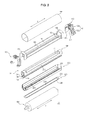
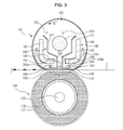
- FIGS. 2 and 3 are respectively an exploded perspective view and a sectional view illustrating the fusing device according to an embodiment.
- FIG. 4 is a sectional view illustrating a configuration of a longitudinal end of the fusing device according to the embodiment.
- the fusing device 70 includes a heating unit 102 and a pressure roller 104.
- a longitudinal direction X of the fusing device 70 is defined as a direction corresponding to an axial direction of the pressure roller 104.
- the longitudinal direction X of the fusing device 70 may be represented as a longitudinal direction of a constituent element of the heating unit 102 including, e.g., a fusing belt 140, a belt guide member 200, or a nip plate 220.
- the heating unit 102 and the pressure roller 104 are arranged to face each other to define a fusing nip N through which the recording medium S passes.
- the heating unit 102 may be arranged to come into contact with a surface of the recording medium S on which a non-fused image has been formed, so as to apply heat to the recording medium S.
- the pressure roller 104 is arranged to come into contact with the heating unit 102 at a pressure.
- the heating unit 102 includes a heat source 120 to generate heat and the fusing belt 140 rotatably placed around the heat source 120.
- the fusing belt 140 is rotatably engaged with the pressure roller 104.
- the pressure roller 104 is arranged to face the fusing belt 140.
- the pressure roller 104 comes into close contact with the fusing belt 140 to define the fusing nip N when a predetermined pressure is applied thereto.
- the pressure roller 104 is rotated upon receiving power from the drive source (not shown) mounted in the main body 10. While the recording medium S, on which the developer image has been transferred, passes through the fusing nip N between the pressure roller 104 and the fusing belt 140, the developer image is fixed to the recording medium S by heat and pressure.
- the pressure roller 104 includes a shaft 105 and an elastic layer 106.
- the shaft 105 is located in the center of the pressure roller 104 and functions as a rotating shaft.
- the shaft 105 also functions to support elements placed thereon.
- the shaft 105 may be made of a metallic material, such as aluminum or steel.
- the elastic layer 106 is configured to surround the shaft 105 and is elastically deformed when the pressure roller 104 comes into contact with the fusing belt 140 at a pressure, thereby allowing the fusing nip N to be defined between the pressure roller 104 and the fusing belt 140.
- the elastic layer 106 may conventionally be made of silicon rubber.
- a release layer 107 may be provided on a surface of the elastic layer 106 to prevent the recording medium from being adhered to the pressure roller 104.
- the release layer 107 may be a tubular layer made of fluorine resin, such as perfluoroalkoxy (PFA).
- Both ends of the fusing belt 140 with respect to a longitudinal direction X of the fusing belt 140 are rotatably supported by side frames 160.
- the fusing belt 140 is heated by the heat source 120 and transfers heat to the recording medium S passing through the fusing nip N.
- the heat source 120 is placed inside the fusing belt 140. As both ends of the heat source 120 are respectively coupled to side covers (not shown) and the side covers (not shown) are secured to the side frames 160, the heat source 120 is supported by the side frames 160.
- the heat source 120 may include at least one halogen lamp.
- the side frames 160 are respectively arranged at opposite sides of the fusing belt 140 in the longitudinal direction X of the fusing belt 140.
- Each of the side frames 160 includes a restraint wall 162 to prevent longitudinal movement of the fusing belt 140 and a side belt guide 170 to support an inner surface of the end of the fusing belt 140.
- the restraint wall 162 includes two legs 162a arranged side by side with a distance therebetween and a connector 162b to connect the two legs 162a to each other.
- the side belt guide 170 protrudes from the restraint wall 162 and is inserted into the fusing belt 140.
- the side belt guide 170 has an arcuate shape and extends throughout the two legs 162a and the connector 162b.
- An outer circumference of the side belt guide 170 supports the inner surface of the end of the fusing belt 140 to guide rotation of the fusing belt 140.
- a support member 180 is placed between the two side frames 160.
- the support member 180 functions as a basic framework to support constituent elements of the heating unit 102 and thus, may be made of a material having high rigidity so as not to be easily deformed by external force.
- the support member 180 may include support plates 182, bending plates 184 and connecting plates 186.
- the support plates 182 extend in the longitudinal direction X of the fusing device 70 between the two side frames 160 and are arranged in parallel to each other with a distance therebetween.
- the connecting plates 186 connect longitudinal ends of the support plates 182 to each other.
- the connecting plates 186 are inserted into the side frames 160 so as to be coupled thereto.
- An assembly of the support member 180 and the side frames 160 defines a framework of the heating unit 102.
- the bending plates 184 are bent inward from the support plates 182.
- the bending plates 184 are seated on an inner surface of the belt guide member 200 to support the belt guide member 200.
- the bending plates 184 define a first opening 188 therebetween. Heat radiated from the heat source 120 is partially transferred to the fusing nip N through the first opening 188.
- the support member 180 has a second opening 190 at an opposite side of the first opening 188.
- the second opening 190 allows the heat radiated from the heat source 120 to directly pass through the support member 180 to thereby directly reach the fusing belt 140.
- the belt guide member 200 supports an inner surface 142 of the fusing belt 140 near the fusing nip N and guides rotation of the fusing belt 140.
- the belt guide member 200 extends in the longitudinal direction X of the fusing belt 140.
- the belt guide member 200 is provided at both longitudinal ends thereof with hooks 202 protruding toward the support member 180.
- the support plates 182 of the support member 180 have fastening holes 183 corresponding to the hooks 202. As the hooks 202 are inserted between the support plates 182 and then, noses of the hooks 202 are caught by the fastening holes 183, the belt guide member 200 is coupled to the support member 180.
- the belt guide member 200 has a third opening 204 corresponding to the first opening 188 of the support member 180.
- the heat radiated from the heat source 120 may be directly transferred to the fusing nip N through the first opening 188 of the support member 180 and the third opening 204 of the belt guide member 200.
- the belt guide member 200 includes a first guide 200a and a second guide 200b respectively arranged upstream and downstream of the third opening 204 with respect to a rotating direction R of the fusing belt 140.
- the first guide 200a and the second guide 200b have arcuate outer surfaces to guide smooth rotation of the fusing belt 140. Ends of the first guide 200a and the second guide 200b of the belt guide member 200 are connected to both ends of the arcuate side belt guide 170 (see FIG. 7 ).
- An outer surface of the belt guide member 200 facing the inner surface 142 of the fusing belt 140 is provided with an accommodation groove 206 in the longitudinal direction X of the fusing belt 140.
- the accommodation groove 206 communicates with the third opening 204 of the belt guide member 200.
- the accommodation groove 206 extends in opposite directions from the third opening 204 such that a part of the groove 206 is formed in the first guide 200a and another part of the groove 206 is formed in the second guide 200b.
- the nip plate 220 is placed in the accommodation groove 206 of the belt guide member 200.
- the nip plate 220 supports the inner surface 142 of the fusing belt 140 to ensure that the fusing nip N is defined between an outer surface of the fusing belt 140 and the pressure roller 104.
- the nip plate 220 has a first surface 222 facing the inner surface 142 of the fusing belt 140 and a second surface 224 opposite the first surface 222.
- the nip plate 220 includes a pressure portion 226 extending in the longitudinal direction X of the fusing belt 140.
- the pressure portion 226 comes into contact with the inner surface 142 of the fusing belt 140 and is arranged to face the pressure roller 104 so as to apply pressure to the fusing belt 140.
- Rim walls 228 protrude from opposite transversal ends of the second surface 224 of the pressure portion 226.
- the belt guide member 200 includes sidewalls 208 extending in a direction away from the fusing belt 140 so as to define the accommodation groove 206.
- the rim walls 228 of the nip plate 220 are supported by the sidewalls 208 of the belt guide member 200.
- the nip plate 220 may be made of a material having low specific heat and high thermal conductivity to efficiently transfer heat to the recording medium.
- the nip plate 220 may be made of aluminum.
- the nip plate 220 may be provided with an oxide film (not shown) via anodizing, and a ceramic-Teflon coating layer may be formed on the oxide film.
- the nip plate 220 applies pressure to the inner surface 142 of the fusing belt 140 which applies pressure to the outer surface of the fusing belt 140. If excessive friction occurs between the fusing belt 140 and the nip plate 220, the fusing belt 140 may be damaged or efficient rotation of the fusing belt 140 may be impossible. Thus, to reduce friction between the fusing belt 140 and the nip plate 220, a lubricant, such as grease, may be applied to the inner surface 142 of the fusing belt 140.
- a heat transfer member 240 may be placed between the heat source 120 and the fusing belt 140.
- the heat transfer member 240 includes a body 242 and first and second legs 244 and 246.
- the body 242 is configured to surround the heat source 120 and is heated by the heat source 120.
- the first leg 244 extends from one end of the body 242 toward the fusing belt 140 and the second leg 246 extends from the other end of the body 242 toward the fusing belt 140.
- the first leg 244 and the second leg 246 are fitted through the first opening 188 of the support member 180 and the third opening 204 of the belt guide member 200.
- An inner surface of the belt guide member 200 defining the third opening 204 supports outer surfaces of the first leg 244 and the second leg 246 of the heat transfer member 240.
- the end of the first leg 244 is bent toward the first guide 200a of the belt guide member 200 to form a first heat transfer portion 248.
- the end of the second leg 246 is bent toward the second guide 200b of the belt guide member 200 to form a second heat transfer portion 250.
- Each of the first heat transfer portion 248 and the second heat transfer portion 250 has one surface coming into contact with the nip plate 220 to transfer heat to the nip plate 220, the other surface of the first heat transfer portion 248 or the second heat transfer portion 250 being supported by the outer surface of the belt guide member 200.
- a fourth opening 252 is defined between the first leg 244 and the second leg 246.
- the heat source 120 directly heats the nip plate 220 through the fourth opening 252 of the heat transfer member 240, and the heated nip plate 220 transfers heat to the fusing belt 140.
- the body 242 of the heat transfer member 240 further includes a fifth opening 254 at an opposite side of the fourth opening 252.
- the heat source 120 may directly heat the fusing belt 140 through the fifth opening 254 of the heat transfer member 240 and the second opening 190 of the support member 180. This may allow a more rapid increase in the temperature of the fusing belt 140 and may prevent the temperature of the fusing belt 140 from dropping during rotation of the fusing belt 140.
- FIG. 5 is a perspective view illustrating the end of the fusing device according to an embodiment.
- the fusing belt is omitted.
- a lubricant receptacle 210 is provided in a longitudinal end of the belt guide member 200.
- FIGS. 4 and 5 illustrate the lubricant receptacle 210 as being provided in one end of the belt guide member 200, another lubricant receptacle may further be provided in the other end of the belt guide member 200.
- a space is defined between the lubricant receptacle 210 and the inner surface 142 of the fusing belt 140.
- the space serves to accommodate the lubricant on the inner surface 142 of the fusing belt 140 when the lubricant is pushed to a longitudinal end of the fusing belt 140 by pressure applied to the fusing nip N.
- the lubricant receptacle 210 serves to prevent the lubricant from leaking to the outer surface of the fusing belt 140. This may prevent contamination of recording media and peripheral elements due to lubricant leakage. In addition, damage of the fusing belt 140 caused when friction between the fusing belt 140 and the nip plate 220 increases by lubricant leakage may be prevented. Preventing lubricant leakage may also prevent slippage of the fusing belt 140 relative to the pressure roller 104.
- the lubricant receptacle 210 may be defined by the sidewalls 208 of the belt guide member 200 extending in the direction away from the fusing belt 140 and a stepped portion 230 of the nip plate 220 placed between the sidewalls 208.
- the stepped portion 230 of the nip plate 220 is located at an outer side of the pressure portion 226 with respect to a longitudinal direction X of the nip plate 220.
- the stepped portion 230 of the nip plate 220 defines a lubricant accommodation space with the inner surface 142 of the fusing belt 140.
- the first surface 222 of the nip plate 220 corresponding to the stepped portion 230 is spaced apart from the inner surface 142 of the fusing belt 140.
- the pressure portion 226 and the stepped portion 230 of the nip plate 220 are connected to each other via an extension 232.
- the extension 232 is bent from the pressure portion 226 to extend in a direction away from the inner surface 142 of the fusing belt 140.
- the stepped portion 230 is bent from the extension 232 to extend in the longitudinal direction of the fusing belt 140.
- the bending junction 234 of the nip plate 220 may have a high possibility of damaging the inner surface 142 of the fusing belt 140.
- the bending junction 234 of the nip plate 220 may be located at the outer side of the elastic layer 106 of the pressure roller 104 with respect to the axial direction X of the pressure roller 104.
- a distance d between the elastic layer 106 and the bending junction 234 of the nip plate 220 with respect to the axial direction X of the pressure roller 104 may be in a range of 2 mm to 5 mm.
- the pressure roller 104 may axially move within a predetermined range due to an assembly tolerance thereof during operation of the fusing device 70, and the elastic layer 106 of the pressure roller 104 may axially expand when heated. If the distance d between the elastic layer 106 of the pressure roller 104 and the bending junction 234 of the nip plate 220 is less than 2 mm, the elastic layer 106 may apply pressure to the bending junction 234 upon axial movement and expansion of the pressure roller 104, causing damage to the fusing belt 140.
- grooves 212 may be formed in ends of the first guide 200a and the second guide 200b with respect to the longitudinal direction X of the belt guide member 200.
- the grooves 212 extend in a rotating direction of the fusing belt 140.
- the grooves 212 provide a lubricant accommodation space between the longitudinal ends of the first guide 200a and the second guide 200b and the inner surface 142 of the fusing belt 140, thereby preventing lubricant leakage.
- FIGS. 4 and 5 illustrate an embodiment in which the stepped portion 230 of the nip plate 220 defines one wall of the lubricant receptacle 210, another embodiment in which the lubricant receptacle is defined without the stepped portion 230 of the nip plate 220 may be possible.
- a lubricant receptacle 210a may be defined by sidewalls 208a and a bottom wall 209 of the belt guide member 201.
- the sidewalls 208a of the belt guide member 201 extend in a direction away from the inner surface 142 of the fusing belt 140.
- the bottom wall 209 of the belt guide member 201 is spaced apart from the inner surface 142 of the fusing belt 140.
- a nip plate 220a may include a pressure portion 226a located to apply pressure to the inner surface 142 of the fusing belt 140, and an extension 232a bent from the pressure portion 226a into the lubricant receptacle 210a.
- the fusing device 70 has a configuration to return the lubricant pushed to the longitudinal end of the fusing belt 140 toward the longitudinal center of the fusing belt 140 during rotation of the fusing belt 140.
- FIG. 7 is a sectional view taken along the line I-I of FIG. 4
- FIG. 8 is a perspective view illustrating the side frame of the fusing device according to an embodiment
- FIG. 9 is a view explaining lubricant guiding operation of a lubricant guide of the fusing device according to an embodiment.
- the side frame 160 includes a lubricant guide 172 protruding from the side belt guide 170 so as to come into contact with the inner surface 142 of the fusing belt 140 at the longitudinal end of the fusing belt 140.
- the lubricant guide 172 has a ramp 174 inclined from the end toward the center of the fusing belt 140 in the rotating direction R of the fusing belt 140.
- An outer end 174a of the ramp 174 is located upstream of an inner end 174b of the slope 174 with respect to the rotating direction R of the fusing belt 140.
- the lubricant on the end of the fusing belt 140 moves toward the center of the fusing belt 140 under guidance of the ramp 174 of the lubricant guide 172 during rotation of the fusing belt 140. This may prevent leakage of the lubricant to the outside of the fusing belt 140.
- the arrows M diagrammatically show the lubricant guided by the lubricant guide 172 during rotation of the fusing belt 140.
- a plurality of lubricant guides 172 may be arranged on the outer circumference of the belt guide 170 in the rotating direction R of the fusing belt 140.
- FIG. 7 illustrates an embodiment in which three lubricant guides 172 are arranged, the number of the lubricant guides 172 may be changed.
- two lubricant guides 172a and 172b may be arranged respectively at both ends of the side belt guide 170 connected to the first guide 200a and the second guide 200b of the belt guide member 200.
- the belt guide member 200 is located near the fusing nip N and thus, relatively great pressure is applied between the belt guide member 200 and the fusing belt 140.
- the lubricant guide 172a located adjacent to the first guide 200a acts to move the lubricant toward the center of the fusing belt 140 before the fusing belt 140 passes the belt guide member 200.
- the lubricant guide 172b located adjacent to the second guide 200b returns the lubricant, which has been pushed to the longitudinal end of the fusing belt 140 while the fusing belt 140 passes the belt guide member 200, toward the center of the fusing belt 140.
- the other lubricant guide 172c may be located at the center of the side belt guide 170 with respect to the rotating direction of the fusing belt 140.
- the side belt guide 170 may be provided with a lubricant accommodation channel 176.
- the lubricant accommodation channel 176 is located between the lubricant guide 172 and the restraint wall 162 with respect to the longitudinal direction X of the fusing belt 140.
- the lubricant accommodation channel 176 may be elongated in the rotating direction of the fusing belt 140.
- the lubricant accommodation channel 176 serves to accommodate the lubricant pushed outward of the lubricant guide 172, thereby preventing leakage of the lubricant to the outside of the fusing belt 140.
- the side belt guide 170 may include a first portion 170a protruding from the restraint wall 162 of the side frame 160 toward the center of the fusing belt 140, and a second portion 170b extending from the first portion 170a toward the center of the fusing belt 140, the second portion 170b being inclined relative to the first portion 170a in a direction away from the inner surface 142 of the fusing belt 140.
- the second portion 170b of the side belt guide 170 is spaced apart from the inner surface 142 of the fusing belt 140 by a predetermined distance, providing a space for accommodation of the lubricant guided inward of the fusing belt 140 by the lubricant guide 172.
- FIG. 10 is a plan view illustrating the side frame provided with a lubricant guide according to another embodiment.
- a lubricant guide 173 may have a symmetrical shape about an axis A parallel to the longitudinal direction X of the fusing belt 140.
- the lubricant guide 173 may include a first ramp 174c and a second ramp 174d that are symmetrical to each other.
- An embodiment may have an advantage of using the same side frame 160a at either side of the fusing belt 140.
- one or more embodiments include a fusing device to prevent a lubricant applied to an inner surface of a fusing belt from leaking to an outer surface of the fusing belt.
- Preventing leakage of the lubricant may prevent contamination of recording media and peripheral elements. Further, there is less risk of increasing friction between the inner surface of the fusing belt and a nip plate because the lubricant is not leaked from the inner surface of the fusing belt, and thus, the fusing belt is free from frictional damage. Furthermore, it may be possible to prevent slippage between the fusing belt and a pressure roller due to lubricant leakage.
Landscapes
- Physics & Mathematics (AREA)
- General Physics & Mathematics (AREA)
- Fixing For Electrophotography (AREA)
Abstract
Description
- Embodiments relate to a fusing device to fix an image to a recording medium and an image forming apparatus having the same.
- An image forming apparatus is designed to print an image on a recording medium. Examples of image forming apparatuses include printers, copiers, fax machines, and devices combining functions thereof.
- In an electro-photographic image forming apparatus, a photoconductor, which has been charged with a predetermined electric potential, is exposed to light such that an electrostatic latent image is formed on a surface of the photoconductor. Thereafter, developer is fed to the electrostatic latent image to form a visible image. The visible image formed on the photoconductor is transferred to a recording medium and then, is fixed to the recording medium while passing through a fusing device.
- A generally widely used fusing device includes a heating unit containing a heat source therein, and a pressure unit arranged to come into close contact with the heating unit to define a fusing nip with the heating unit. If the recording medium, on which the image has been transferred, is introduced into the fusing nip between the heating unit and the pressure unit, the image is fixed to the recording medium by heat and pressure.
- The heating unit and the pressure unit of the fusing device include rotators including rollers, a belt, etc. To reduce frictional resistance of the rotators so as to ensure smooth rotation of the rotators, a lubricant is applied to the rotators.
- It is an aspect of one or more embodiments to provide a fusing device to maintain fusing performance via smooth operation of constituent elements, and an image forming apparatus having the same.
- It is another aspect of one or more embodiments to provide a fusing device to reduce leakage of a lubricant and an image forming apparatus having the same.
- Additional aspects of the invention will be set forth in part in the description which follows and, in part, will be apparent from the description, or may be learned by practice of the invention.
- According to the present invention there is provided an apparatus and method as set forth in the appended claims. Other features of the invention will be apparent from the dependent claims, and the description which follows.
- In accordance with an aspect of one or more embodiments, a fusing device includes a fusing belt disposed in a rotatable manner, a heat source placed in the fusing belt to heat the fusing belt, a pressure roller placed to apply pressure to an outer surface of the fusing belt, and a nip plate to support an inner surface of the fusing belt so as to define a fusing nip between the fusing belt and the pressure roller, wherein the nip plate includes a pressure portion arranged to face the pressure roller and to apply pressure to the inner surface of the fusing belt, and a stepped portion located at an outer side of the pressure portion with respect to a longitudinal direction of the nip plate, the stepped portion being spaced apart from the inner surface of the fusing belt so as to define a space for accommodation of a lubricant applied to the inner surface of the fusing belt.
- The fusing device may further include a side frame placed to rotatably support a longitudinal end of the fusing belt, and the side frame may include a side belt guide inserted in the fusing belt so as to support the inner surface of the fusing belt, and at least one lubricant guide protruding from the side belt guide to guide the lubricant on the end of the fusing belt toward the center of the fusing belt.
- The nip plate may include an extension bent from the pressure portion to extend in a direction away from the inner surface of the fusing belt.
- The pressure roller may include a shaft, and an elastic layer surrounding the circumference of the shaft to define the fusing nip when the pressure roller is pushed toward the nip plate, and a bending junction of the nip plate where the pressure portion and the extension meet each other may be located at an outer side of the elastic layer with respect to an axial direction of the pressure roller.
- A distance between the elastic layer and the bending junction of the nip plate with respect to the axial direction of the pressure roller may be in a range of about 2 mm to about 5 mm.
- The fusing device may further include a belt guide member placed near the fusing nip to guide the inner surface of the fusing belt, the belt guide member may include sidewalls extending in a direction away from the fusing belt to define a space with the inner surface of the fusing belt, and the space for accommodation of the lubricant may be defined by the stepped portion of the nip plate and the sidewalls of the belt guide member.
- The lubricant guide may include a ramp inclined from the end of the fusing belt toward the center of the fusing belt in a rotating direction of the fusing belt.
- The lubricant guide may have a symmetrical shape about an axis parallel to the longitudinal direction of the fusing belt.
- The side belt guide may extend in an arcuate shape along an inner surface of the fusing belt, and the at least one lubricant guide may include a plurality of lubricant guides arranged on an outer circumference of the side belt guide in the rotating direction of the fusing belt.
- The side frame may further include a restraint wall to limit longitudinal movement of the fusing belt, and the side belt guide may include a lubricant accommodation channel provided between the lubricant guide and the restraint wall with respect to a longitudinal direction of the fusing belt, the lubricant accommodation channel extending in a rotating direction of the fusing belt.
- The side belt guide may include a first portion extending toward the center of the fusing belt, and a second portion extending from the first portion toward the center of the fusing belt, the second portion being inclined relative to the first portion in a direction away from the inner surface of the fusing belt.
- In accordance with another aspect of one or more embodiments, a fusing device includes a heat source to generate heat, a fusing belt to rotate around the heat source, the fusing belt being heated by the heat source, a pressure roller to come into contact with an outer surface of the fusing belt at a pressure, a side frame including a side belt guide to rotatably support an inner surface of the fusing belt at a longitudinal end of the fusing belt, and at least one lubricant guide protruding from the side belt guide to guide the lubricant on the end of the fusing belt toward the center of the fusing belt during rotation of the fusing belt, a nip plate including a pressure portion arranged to face the pressure roller and adapted to apply pressure to the inner surface of the fusing belt so as to define a fusing nip between the fusing belt and the pressure roller, and a belt guide member to support the nip plate and guide the inner surface of the fusing belt near the fusing nip, the belt guide member including a lubricant receptacle defining a space with the inner surface of the fusing belt for accommodation of the lubricant on the inner surface of the fusing belt when the lubricant is pushed to the longitudinal end of the fusing belt by the pressure applied to the fusing nip.
- The nip plate may include an extension bent from the pressure portion to extend in a direction away from the inner surface of the fusing belt, and a stepped portion located in the lubricant receptacle of the belt guide member and spaced apart from the inner surface of the fusing belt.
- The pressure roller may include a shaft, and an elastic layer surrounding the circumference of the shaft to define the fusing nip when the pressure roller is pushed toward the nip plate, and the lubricant receptacle of the belt guide member may be located at an outer side of the elastic layer with respect to an axial direction of the pressure roller.
- The belt guide member may include an arcuate first guide to guide the inner surface of the fusing belt at an upstream position of the nip plate with respect to a rotating direction of the fusing belt, and an arcuate second guide to guide the inner surface of the fusing belt at a downstream position of the nip plate with respect to the rotating direction of the fusing belt, and the first guide and the second guide of the belt guide member may be provided at longitudinal ends thereof with grooves extending in the rotating direction of the fusing belt.
- The lubricant guide of the side frame may include a ramp inclined from the end of the fusing belt toward the center of the fusing belt in the rotating direction of the fusing belt.
- The side belt guide may have an arcuate shape, both ends of the arcuate side belt guide may be connected respectively to the first guide and the second guide of the belt guide member, and the at least one lubricant guide may include a plurality of lubricant guides arranged on an outer circumference of the side belt guide in the rotating direction of the fusing belt.
- Two of the lubricant guides may be arranged adjacent to the respective ends of the side belt guide connected to the first guide and the second guide of the belt guide member, and another lubricant guide may be located at the center of the side belt guide with respect to the rotating direction of the fusing belt.
- In accordance with a further aspect of one or more embodiments, an image forming apparatus includes a fusing device to apply heat and pressure to a recording medium passing through a fusing nip so as to fix a non-fused image to the recording medium, wherein the fusing device includes a heat source to generate heat, a fusing belt placed to be heated by the heat source, the fusing belt coming into contact with a surface of the recording medium on which the non-fused image has been formed so as to transfer heat thereto, a pressure roller to come into contact with an outer surface of the fusing belt at a pressure, a nip plate to support an inner surface of the fusing belt so as to define a fusing nip between the fusing belt and the pressure roller, the nip plate including a pressure portion arranged to face the pressure roller and adapted to apply pressure to the inner surface of the fusing belt and a stepped portion located at an outer side of the pressure portion with respect to a longitudinal direction of the nip plate, the stepped portion being spaced apart from the inner surface of the fusing belt so as to define a space for accommodation of a lubricant applied to the inner surface of the fusing belt, and a belt guide member placed to accommodate the nip plate and guide the inner surface of the fusing belt near the fusing nip, the belt guide member having an opening to allow heat radiated from the heat source to be directly transferred to the nip plate, a support member placed to support the belt guide member and having an opening to directly pass the heat radiated from the heat source, and a heat transfer member placed between the heat source and the fusing belt, the heat transfer member including a body configured to surround the heat source and heated by the heat source, an opening to allow heat radiated from the heat source to be directly transferred to the fusing belt, and a heat transfer portion to come into contact with the nip plate.
- These and/or other aspects of one or more embodiments will become apparent and more readily appreciated from the following description of embodiments, taken in conjunction with the accompanying drawings of which:
-
FIG. 1 is a view illustrating a configuration of an image forming apparatus according to an embodiment; -
FIGS. 2 and3 are respectively an exploded perspective view and a sectional view illustrating a configuration of a fusing device according to an embodiment; -
FIG. 4 is a sectional view illustrating a configuration of a longitudinal end of the fusing device according to an embodiment; -
FIG. 5 is a perspective view illustrating the end of the fusing device according to an embodiment; -
FIG. 6 is a view illustrating an alternative embodiment in which a lubricant receptacle is defined without a stepped portion of a nip plate; -
FIG. 7 is a sectional view taken along the line I-I ofFIG. 4 ; -
FIG. 8 is a perspective view illustrating a side frame of the fusing device according to an embodiment; -
FIG. 9 is a view explaining lubricant guiding operation of a lubricant guide of the fusing device according to an embodiment; and -
FIG. 10 is a plan view illustrating a side frame provided with a lubricant guide according to another embodiment. - Reference will now be made in detail to embodiments of, examples of which are illustrated in the accompanying drawings, wherein like reference numerals refer to like elements throughout.
FIG. 1 is a view illustrating a configuration of an image forming apparatus according to an embodiment. - As illustrated in
FIG. 1 , theimage forming apparatus 1 includes amain body 10, a recordingmedium feeding device 20, alight scanning device 30, a plurality ofphotoconductors device 50, atransfer device 60, afusing device 70, and a recordingmedium discharge device 80. - The
main body 10 defines an external appearance of the image forming apparatus and supports a variety of elements installed therein. Themain body 10 may be provided with an opening/closing part to allow the user to access the interior of themain body 10 through an opening of themain body 10 when it is desired to replace or repair the variety of elements or to remove a recording medium jammed in themain body 10. - The recording
medium feeding device 20 feeds recording media S toward thetransfer device 60. The recordingmedium feeding device 20 includes acassette 22 in which the recording media S are accommodated, apickup roller 24 to pick up the recording media S accommodated in thecassette 22 one by one, anddelivery rollers 26 to deliver the picked-up recording medium toward thetransfer device 60. - The
light scanning device 30 irradiates light corresponding to image information to thephotoconductors photoconductors light scanning device 30 may include a light source to emit light beams, a deflector including a polygonal mirror to deflect the light beams when rotated by a motor, and an f-theta lens to focus the deflected light beams to thephotoconductors - The developing
device 50 forms visible images by supplying developers to the electrostatic latent images formed on thephotoconductors device 50 consists of four developingunits - The developing
units chargers 52,developer reservoirs 54,developer delivery members 56, and developingmembers 58. Thechargers 52 charge the surfaces of thephotoconductors photoconductors developer delivery members 56 deliver the developers stored in thedeveloper reservoirs 54 to the developingmembers 58. The developingmembers 58 supply the developers to the electrostatic latent images formed on thephotoconductors - Although
FIG. 1 illustrates an embodiment in which the fourphotoconductors units - The
transfer device 60 transfers the visible images from thephotoconductors transfer device 60 includes atransfer belt 61, adrive roller 62, asupport roller 63,tension rollers transfer rollers - The
transfer belt 61 is rotatably supported by thedrive roller 62 and thesupport roller 63. Thedrive roller 62 is rotated upon receiving power from a drive source (not shown) mounted in themain body 10. Thesupport roller 63 is located at an opposite side of thedrive roller 62 to support an inner surface of thetransfer belt 61. - The
respective photoconductors transfer belt 61. Thetransfer rollers transfer belt 61 at positions corresponding to therespective photoconductors - When the
image forming apparatus 1 performs a color printing operation, thetransfer rollers respective photoconductors transfer rollers respective photoconductors transfer belt 61 such that the images overlap one another on thetransfer belt 61. The resulting image on thetransfer belt 61 is transferred to the recording medium fed from the recordingmedium feeding device 20 while the recording medium passes between thetransfer roller 67 and thetransfer belt 61. - On the other hand, when the
image forming apparatus 1 performs a black-and-white printing operation, only thetransfer roller 66K is pushed toward thephotoconductor 40K, and theother transfer rollers photoconductors - The recording medium having passed through the
transfer device 60 enters thefusing device 70. As thefusing device 70 applies heat and pressure to the recording medium, the non-fused image on the recording medium is fixed to the recording medium. - The recording medium having passed through the fusing
device 70 is guided to the recordingmedium discharge device 80 to thereby be discharged out of themain body 10 by the recordingmedium discharge device 80. The recordingmedium discharge device 80 includes adischarge roller 82 and adischarge backup roller 84 facing thedischarge roller 82. -
FIGS. 2 and3 are respectively an exploded perspective view and a sectional view illustrating the fusing device according to an embodiment.FIG. 4 is a sectional view illustrating a configuration of a longitudinal end of the fusing device according to the embodiment. - As illustrated in
FIGS. 2 to 4 , the fusingdevice 70 includes aheating unit 102 and apressure roller 104. In the following description, a longitudinal direction X of thefusing device 70 is defined as a direction corresponding to an axial direction of thepressure roller 104. The longitudinal direction X of thefusing device 70 may be represented as a longitudinal direction of a constituent element of theheating unit 102 including, e.g., a fusingbelt 140, abelt guide member 200, or a nipplate 220. - The
heating unit 102 and thepressure roller 104 are arranged to face each other to define a fusing nip N through which the recording medium S passes. Theheating unit 102 may be arranged to come into contact with a surface of the recording medium S on which a non-fused image has been formed, so as to apply heat to the recording medium S. Thepressure roller 104 is arranged to come into contact with theheating unit 102 at a pressure. - The
heating unit 102 includes aheat source 120 to generate heat and the fusingbelt 140 rotatably placed around theheat source 120. The fusingbelt 140 is rotatably engaged with thepressure roller 104. - The
pressure roller 104 is arranged to face the fusingbelt 140. Thepressure roller 104 comes into close contact with the fusingbelt 140 to define the fusing nip N when a predetermined pressure is applied thereto. Thepressure roller 104 is rotated upon receiving power from the drive source (not shown) mounted in themain body 10. While the recording medium S, on which the developer image has been transferred, passes through the fusing nip N between thepressure roller 104 and the fusingbelt 140, the developer image is fixed to the recording medium S by heat and pressure. - The
pressure roller 104 includes ashaft 105 and anelastic layer 106. Theshaft 105 is located in the center of thepressure roller 104 and functions as a rotating shaft. Theshaft 105 also functions to support elements placed thereon. Theshaft 105 may be made of a metallic material, such as aluminum or steel. Theelastic layer 106 is configured to surround theshaft 105 and is elastically deformed when thepressure roller 104 comes into contact with the fusingbelt 140 at a pressure, thereby allowing the fusing nip N to be defined between thepressure roller 104 and the fusingbelt 140. Theelastic layer 106 may conventionally be made of silicon rubber. - A
release layer 107 may be provided on a surface of theelastic layer 106 to prevent the recording medium from being adhered to thepressure roller 104. Therelease layer 107 may be a tubular layer made of fluorine resin, such as perfluoroalkoxy (PFA). - Both ends of the fusing
belt 140 with respect to a longitudinal direction X of the fusingbelt 140 are rotatably supported by side frames 160. The fusingbelt 140 is heated by theheat source 120 and transfers heat to the recording medium S passing through the fusing nip N. - The
heat source 120 is placed inside the fusingbelt 140. As both ends of theheat source 120 are respectively coupled to side covers (not shown) and the side covers (not shown) are secured to the side frames 160, theheat source 120 is supported by the side frames 160. Theheat source 120 may include at least one halogen lamp. - The side frames 160 are respectively arranged at opposite sides of the fusing
belt 140 in the longitudinal direction X of the fusingbelt 140. Each of the side frames 160 includes arestraint wall 162 to prevent longitudinal movement of the fusingbelt 140 and aside belt guide 170 to support an inner surface of the end of the fusingbelt 140. Therestraint wall 162 includes twolegs 162a arranged side by side with a distance therebetween and aconnector 162b to connect the twolegs 162a to each other. - The
side belt guide 170 protrudes from therestraint wall 162 and is inserted into the fusingbelt 140. Theside belt guide 170 has an arcuate shape and extends throughout the twolegs 162a and theconnector 162b. An outer circumference of theside belt guide 170 supports the inner surface of the end of the fusingbelt 140 to guide rotation of the fusingbelt 140. - A
support member 180 is placed between the two side frames 160. Thesupport member 180 functions as a basic framework to support constituent elements of theheating unit 102 and thus, may be made of a material having high rigidity so as not to be easily deformed by external force. - The
support member 180 may includesupport plates 182, bendingplates 184 and connectingplates 186. - The
support plates 182 extend in the longitudinal direction X of thefusing device 70 between the twoside frames 160 and are arranged in parallel to each other with a distance therebetween. The connectingplates 186 connect longitudinal ends of thesupport plates 182 to each other. The connectingplates 186 are inserted into the side frames 160 so as to be coupled thereto. An assembly of thesupport member 180 and the side frames 160 defines a framework of theheating unit 102. - The bending
plates 184 are bent inward from thesupport plates 182. The bendingplates 184 are seated on an inner surface of thebelt guide member 200 to support thebelt guide member 200. - The bending
plates 184 define afirst opening 188 therebetween. Heat radiated from theheat source 120 is partially transferred to the fusing nip N through thefirst opening 188. - The
support member 180 has asecond opening 190 at an opposite side of thefirst opening 188. Thesecond opening 190 allows the heat radiated from theheat source 120 to directly pass through thesupport member 180 to thereby directly reach the fusingbelt 140. - The
belt guide member 200 supports aninner surface 142 of the fusingbelt 140 near the fusing nip N and guides rotation of the fusingbelt 140. Thebelt guide member 200 extends in the longitudinal direction X of the fusingbelt 140. - The
belt guide member 200 is provided at both longitudinal ends thereof withhooks 202 protruding toward thesupport member 180. Thesupport plates 182 of thesupport member 180 havefastening holes 183 corresponding to thehooks 202. As thehooks 202 are inserted between thesupport plates 182 and then, noses of thehooks 202 are caught by the fastening holes 183, thebelt guide member 200 is coupled to thesupport member 180. - The
belt guide member 200 has athird opening 204 corresponding to thefirst opening 188 of thesupport member 180. The heat radiated from theheat source 120 may be directly transferred to the fusing nip N through thefirst opening 188 of thesupport member 180 and thethird opening 204 of thebelt guide member 200. - The
belt guide member 200 includes afirst guide 200a and asecond guide 200b respectively arranged upstream and downstream of thethird opening 204 with respect to a rotating direction R of the fusingbelt 140. Thefirst guide 200a and thesecond guide 200b have arcuate outer surfaces to guide smooth rotation of the fusingbelt 140. Ends of thefirst guide 200a and thesecond guide 200b of thebelt guide member 200 are connected to both ends of the arcuate side belt guide 170 (seeFIG. 7 ). - An outer surface of the
belt guide member 200 facing theinner surface 142 of the fusingbelt 140 is provided with anaccommodation groove 206 in the longitudinal direction X of the fusingbelt 140. Theaccommodation groove 206 communicates with thethird opening 204 of thebelt guide member 200. Specifically, theaccommodation groove 206 extends in opposite directions from thethird opening 204 such that a part of thegroove 206 is formed in thefirst guide 200a and another part of thegroove 206 is formed in thesecond guide 200b. - The nip
plate 220 is placed in theaccommodation groove 206 of thebelt guide member 200. The nipplate 220 supports theinner surface 142 of the fusingbelt 140 to ensure that the fusing nip N is defined between an outer surface of the fusingbelt 140 and thepressure roller 104. The nipplate 220 has afirst surface 222 facing theinner surface 142 of the fusingbelt 140 and asecond surface 224 opposite thefirst surface 222. - The nip
plate 220 includes apressure portion 226 extending in the longitudinal direction X of the fusingbelt 140. Thepressure portion 226 comes into contact with theinner surface 142 of the fusingbelt 140 and is arranged to face thepressure roller 104 so as to apply pressure to the fusingbelt 140.Rim walls 228 protrude from opposite transversal ends of thesecond surface 224 of thepressure portion 226. - The
belt guide member 200 includessidewalls 208 extending in a direction away from the fusingbelt 140 so as to define theaccommodation groove 206. When thenip plate 220 is placed in theaccommodation groove 206, therim walls 228 of thenip plate 220 are supported by thesidewalls 208 of thebelt guide member 200. - The nip
plate 220 may be made of a material having low specific heat and high thermal conductivity to efficiently transfer heat to the recording medium. For example, thenip plate 220 may be made of aluminum. Also, thenip plate 220 may be provided with an oxide film (not shown) via anodizing, and a ceramic-Teflon coating layer may be formed on the oxide film. - The nip
plate 220 applies pressure to theinner surface 142 of the fusingbelt 140 which applies pressure to the outer surface of the fusingbelt 140. If excessive friction occurs between the fusingbelt 140 and thenip plate 220, the fusingbelt 140 may be damaged or efficient rotation of the fusingbelt 140 may be impossible. Thus, to reduce friction between the fusingbelt 140 and thenip plate 220, a lubricant, such as grease, may be applied to theinner surface 142 of the fusingbelt 140. - A
heat transfer member 240 may be placed between theheat source 120 and the fusingbelt 140. Theheat transfer member 240 includes abody 242 and first andsecond legs - The
body 242 is configured to surround theheat source 120 and is heated by theheat source 120. Thefirst leg 244 extends from one end of thebody 242 toward the fusingbelt 140 and thesecond leg 246 extends from the other end of thebody 242 toward the fusingbelt 140. Thefirst leg 244 and thesecond leg 246 are fitted through thefirst opening 188 of thesupport member 180 and thethird opening 204 of thebelt guide member 200. An inner surface of thebelt guide member 200 defining thethird opening 204 supports outer surfaces of thefirst leg 244 and thesecond leg 246 of theheat transfer member 240. - The end of the
first leg 244 is bent toward thefirst guide 200a of thebelt guide member 200 to form a firstheat transfer portion 248. The end of thesecond leg 246 is bent toward thesecond guide 200b of thebelt guide member 200 to form a secondheat transfer portion 250. - Each of the first
heat transfer portion 248 and the secondheat transfer portion 250 has one surface coming into contact with thenip plate 220 to transfer heat to the nipplate 220, the other surface of the firstheat transfer portion 248 or the secondheat transfer portion 250 being supported by the outer surface of thebelt guide member 200. - A
fourth opening 252 is defined between thefirst leg 244 and thesecond leg 246. Theheat source 120 directly heats thenip plate 220 through thefourth opening 252 of theheat transfer member 240, and the heated nipplate 220 transfers heat to the fusingbelt 140. - The
body 242 of theheat transfer member 240 further includes afifth opening 254 at an opposite side of thefourth opening 252. Thus, theheat source 120 may directly heat the fusingbelt 140 through thefifth opening 254 of theheat transfer member 240 and thesecond opening 190 of thesupport member 180. This may allow a more rapid increase in the temperature of the fusingbelt 140 and may prevent the temperature of the fusingbelt 140 from dropping during rotation of the fusingbelt 140. -
FIG. 5 is a perspective view illustrating the end of the fusing device according to an embodiment. InFIG. 5 , the fusing belt is omitted. - A
lubricant receptacle 210 is provided in a longitudinal end of thebelt guide member 200. AlthoughFIGS. 4 and5 illustrate thelubricant receptacle 210 as being provided in one end of thebelt guide member 200, another lubricant receptacle may further be provided in the other end of thebelt guide member 200. - A space is defined between the
lubricant receptacle 210 and theinner surface 142 of the fusingbelt 140. The space serves to accommodate the lubricant on theinner surface 142 of the fusingbelt 140 when the lubricant is pushed to a longitudinal end of the fusingbelt 140 by pressure applied to the fusing nip N. - As the lubricant pushed from the fusing nip N to the longitudinal end of the fusing
belt 140 is accommodated in thelubricant receptacle 210, thelubricant receptacle 210 serves to prevent the lubricant from leaking to the outer surface of the fusingbelt 140. This may prevent contamination of recording media and peripheral elements due to lubricant leakage. In addition, damage of the fusingbelt 140 caused when friction between the fusingbelt 140 and thenip plate 220 increases by lubricant leakage may be prevented. Preventing lubricant leakage may also prevent slippage of the fusingbelt 140 relative to thepressure roller 104. - The
lubricant receptacle 210 may be defined by thesidewalls 208 of thebelt guide member 200 extending in the direction away from the fusingbelt 140 and a steppedportion 230 of thenip plate 220 placed between thesidewalls 208. - The stepped
portion 230 of thenip plate 220 is located at an outer side of thepressure portion 226 with respect to a longitudinal direction X of thenip plate 220. The steppedportion 230 of thenip plate 220 defines a lubricant accommodation space with theinner surface 142 of the fusingbelt 140. Thefirst surface 222 of thenip plate 220 corresponding to the steppedportion 230 is spaced apart from theinner surface 142 of the fusingbelt 140. - The
pressure portion 226 and the steppedportion 230 of thenip plate 220 are connected to each other via anextension 232. Theextension 232 is bent from thepressure portion 226 to extend in a direction away from theinner surface 142 of the fusingbelt 140. The steppedportion 230 is bent from theextension 232 to extend in the longitudinal direction of the fusingbelt 140. - If a bending
junction 234 of thenip plate 220 where thepressure portion 226 and theextension 232 meet each other is located to receive pressure applied by thepressure roller 104, the bendingjunction 234 may have a high possibility of damaging theinner surface 142 of the fusingbelt 140. Thus, as illustrated inFIG. 4 , the bendingjunction 234 of thenip plate 220 may be located at the outer side of theelastic layer 106 of thepressure roller 104 with respect to the axial direction X of thepressure roller 104. - A distance d between the
elastic layer 106 and the bendingjunction 234 of thenip plate 220 with respect to the axial direction X of thepressure roller 104 may be in a range of 2 mm to 5 mm. Thepressure roller 104 may axially move within a predetermined range due to an assembly tolerance thereof during operation of thefusing device 70, and theelastic layer 106 of thepressure roller 104 may axially expand when heated. If the distance d between theelastic layer 106 of thepressure roller 104 and the bendingjunction 234 of thenip plate 220 is less than 2 mm, theelastic layer 106 may apply pressure to the bendingjunction 234 upon axial movement and expansion of thepressure roller 104, causing damage to the fusingbelt 140. On the contrary, if the distance d is greater than 5 mm, the lubricant accommodation space is reduced, increasing leakage possibility of the lubricant accommodated in thelubricant receptacle 210 to the outside of the fusingbelt 140. As illustrated inFIG. 5 ,grooves 212 may be formed in ends of thefirst guide 200a and thesecond guide 200b with respect to the longitudinal direction X of thebelt guide member 200. Thegrooves 212 extend in a rotating direction of the fusingbelt 140. Thegrooves 212 provide a lubricant accommodation space between the longitudinal ends of thefirst guide 200a and thesecond guide 200b and theinner surface 142 of the fusingbelt 140, thereby preventing lubricant leakage. - Although
FIGS. 4 and5 illustrate an embodiment in which the steppedportion 230 of thenip plate 220 defines one wall of thelubricant receptacle 210, another embodiment in which the lubricant receptacle is defined without the steppedportion 230 of thenip plate 220 may be possible. - For example, as illustrated in
FIG. 6 , alubricant receptacle 210a may be defined by sidewalls 208a and abottom wall 209 of thebelt guide member 201. - The
sidewalls 208a of thebelt guide member 201 extend in a direction away from theinner surface 142 of the fusingbelt 140. Thebottom wall 209 of thebelt guide member 201 is spaced apart from theinner surface 142 of the fusingbelt 140. - A
nip plate 220a may include apressure portion 226a located to apply pressure to theinner surface 142 of the fusingbelt 140, and anextension 232a bent from thepressure portion 226a into thelubricant receptacle 210a. - The fusing
device 70 has a configuration to return the lubricant pushed to the longitudinal end of the fusingbelt 140 toward the longitudinal center of the fusingbelt 140 during rotation of the fusingbelt 140. -
FIG. 7 is a sectional view taken along the line I-I ofFIG. 4 ,FIG. 8 is a perspective view illustrating the side frame of the fusing device according to an embodiment, andFIG. 9 is a view explaining lubricant guiding operation of a lubricant guide of the fusing device according to an embodiment. - As illustrated in
FIGS. 7 to 9 , theside frame 160 includes alubricant guide 172 protruding from theside belt guide 170 so as to come into contact with theinner surface 142 of the fusingbelt 140 at the longitudinal end of the fusingbelt 140. - The
lubricant guide 172 has aramp 174 inclined from the end toward the center of the fusingbelt 140 in the rotating direction R of the fusingbelt 140. Anouter end 174a of theramp 174 is located upstream of aninner end 174b of theslope 174 with respect to the rotating direction R of the fusingbelt 140. - The lubricant on the end of the fusing
belt 140 moves toward the center of the fusingbelt 140 under guidance of theramp 174 of thelubricant guide 172 during rotation of the fusingbelt 140. This may prevent leakage of the lubricant to the outside of the fusingbelt 140. InFIG. 9 , the arrows M diagrammatically show the lubricant guided by thelubricant guide 172 during rotation of the fusingbelt 140. - A plurality of lubricant guides 172 may be arranged on the outer circumference of the
belt guide 170 in the rotating direction R of the fusingbelt 140. AlthoughFIG. 7 illustrates an embodiment in which three lubricant guides 172 are arranged, the number of the lubricant guides 172 may be changed. - Of the plurality of lubricant guides 172, two
lubricant guides side belt guide 170 connected to thefirst guide 200a and thesecond guide 200b of thebelt guide member 200. Thebelt guide member 200 is located near the fusing nip N and thus, relatively great pressure is applied between thebelt guide member 200 and the fusingbelt 140. Thus, when the fusingbelt 140 passes thebelt guide member 200, a relatively great amount of the lubricant is pushed to the longitudinal end of the fusingbelt 140. Thelubricant guide 172a located adjacent to thefirst guide 200a acts to move the lubricant toward the center of the fusingbelt 140 before the fusingbelt 140 passes thebelt guide member 200. Thelubricant guide 172b located adjacent to thesecond guide 200b returns the lubricant, which has been pushed to the longitudinal end of the fusingbelt 140 while the fusingbelt 140 passes thebelt guide member 200, toward the center of the fusingbelt 140. - The
other lubricant guide 172c may be located at the center of theside belt guide 170 with respect to the rotating direction of the fusingbelt 140. - As illustrated in
FIGS. 4 and8 , theside belt guide 170 may be provided with alubricant accommodation channel 176. Thelubricant accommodation channel 176 is located between thelubricant guide 172 and therestraint wall 162 with respect to the longitudinal direction X of the fusingbelt 140. Thelubricant accommodation channel 176 may be elongated in the rotating direction of the fusingbelt 140. Thelubricant accommodation channel 176 serves to accommodate the lubricant pushed outward of thelubricant guide 172, thereby preventing leakage of the lubricant to the outside of the fusingbelt 140. - The
side belt guide 170 may include afirst portion 170a protruding from therestraint wall 162 of theside frame 160 toward the center of the fusingbelt 140, and asecond portion 170b extending from thefirst portion 170a toward the center of the fusingbelt 140, thesecond portion 170b being inclined relative to thefirst portion 170a in a direction away from theinner surface 142 of the fusingbelt 140. - The
second portion 170b of theside belt guide 170 is spaced apart from theinner surface 142 of the fusingbelt 140 by a predetermined distance, providing a space for accommodation of the lubricant guided inward of the fusingbelt 140 by thelubricant guide 172. -
FIG. 10 is a plan view illustrating the side frame provided with a lubricant guide according to another embodiment. As illustrated inFIG. 10 , alubricant guide 173 may have a symmetrical shape about an axis A parallel to the longitudinal direction X of the fusingbelt 140. Specifically, thelubricant guide 173 may include afirst ramp 174c and asecond ramp 174d that are symmetrical to each other. An embodiment may have an advantage of using thesame side frame 160a at either side of the fusingbelt 140. - As is apparent from the above description, one or more embodiments include a fusing device to prevent a lubricant applied to an inner surface of a fusing belt from leaking to an outer surface of the fusing belt.
- Preventing leakage of the lubricant may prevent contamination of recording media and peripheral elements. Further, there is less risk of increasing friction between the inner surface of the fusing belt and a nip plate because the lubricant is not leaked from the inner surface of the fusing belt, and thus, the fusing belt is free from frictional damage. Furthermore, it may be possible to prevent slippage between the fusing belt and a pressure roller due to lubricant leakage.
- Although an embodiment has been shown and described, it would be appreciated by those skilled in the art that changes may be made in embodiments without departing from the principles of the invention, the scope of which is defined in the claims and their equivalents.
- Attention is directed to all papers and documents which are filed concurrently with or previous to this specification in connection with this application and which are open to public inspection with this specification, and the contents of all such papers and documents are incorporated herein by reference.
- All of the features disclosed in this specification (including any accompanying claims, abstract and drawings), and/or all of the steps of any method or process so disclosed, may be combined in any combination, except combinations where at least some of such features and/or steps are mutually exclusive.
- Each feature disclosed in this specification (including any accompanying claims, abstract and drawings) may be replaced by alternative features serving the same, equivalent or similar purpose, unless expressly stated otherwise. Thus, unless expressly stated otherwise, each feature disclosed is one example only of a generic series of equivalent or similar features.
- The invention is not restricted to the details of the foregoing embodiment(s). The invention extends to any novel one, or any novel combination, of the features disclosed in this specification (including any accompanying claims, abstract and drawings), or to any novel one, or any novel combination, of the steps of any method or process so disclosed.
Claims (15)
- A fusing device comprising:a fusing belt disposed in a rotatable manner;a heat source placed in the fusing belt to heat the fusing belt;a pressure roller placed to apply pressure to an outer surface of the fusing belt; anda nip plate to support an inner surface of the fusing belt so as to define a fusing nip between the fusing belt and the pressure roller,wherein the nip plate includes:a pressure portion arranged to face the pressure roller and to apply pressure to the inner surface of the fusing belt; anda stepped portion located at an outer side of the pressure portion with respect to a longitudinal direction of the nip plate, the stepped portion being spaced apart from the inner surface of the fusing belt so as to define a space for accommodation of a lubricant applied to the inner surface of the fusing belt.
- The fusing device according to claim 1, further comprising a side frame placed to rotatably support a longitudinal end of the fusing belt,
wherein the side frame includes a side belt guide inserted in the fusing belt so as to support the inner surface of the fusing belt, and at least one lubricant guide protruding from the side belt guide to guide the lubricant on the end of the fusing belt toward the center of the fusing belt. - The fusing device according to claim 1, wherein the nip plate includes an extension bent from the pressure portion to extend in a direction away from the inner surface of the fusing belt.
- The fusing device according to claim 3, wherein:the pressure roller includes a shaft, and an elastic layer surrounding the circumference of the shaft to define the fusing nip when the pressure roller is pushed toward the nip plate; anda bending junction of the nip plate where the pressure portion and the extension meet each other is located at an outer side of the elastic layer with respect to an axial direction of the pressure roller.
- The fusing device according to claim 4, wherein a distance between the elastic layer and the bending junction of the nip plate with respect to the axial direction of the pressure roller is in a range of about 2 mm to about 5 mm.
- The fusing device according to claim 1, further comprising a belt guide member placed near the fusing nip to guide the inner surface of the fusing belt,
wherein the belt guide member includes sidewalls extending in a direction away from the fusing belt to define a space with the inner surface of the fusing belt, and
wherein the space for accommodation of the lubricant is defined by the stepped portion of the nip plate and the sidewalls of the belt guide member. - The fusing device according to claim 2, wherein the lubricant guide includes a ramp inclined from the end of the fusing belt toward the center of the fusing belt in a rotating direction of the fusing belt.
- The fusing device according to claim 7, wherein the lubricant guide has a symmetrical shape about an axis parallel to the longitudinal direction of the fusing belt.
- The fusing device according to claim 2, wherein:the side belt guide extends in an arcuate shape along an inner surface of the fusing belt; andthe at least one lubricant guide includes a plurality of lubricant guides arranged on an outer circumference of the side belt guide in the rotating direction of the fusing belt.
- The fusing device according to claim 2, wherein:the side frame further includes a restraint wall to limit longitudinal movement of the fusing belt; andthe side belt guide includes a lubricant accommodation channel provided between the lubricant guide and the restraint wall with respect to a longitudinal direction of the fusing belt, the lubricant accommodation channel extending in a rotating direction of the fusing belt.
- The fusing device according to claim 2, wherein the side belt guide includes a first portion extending toward the center of the fusing belt, and a second portion extending from the first portion toward the center of the fusing belt, the second portion being inclined relative to the first portion in a direction away from the inner surface of the fusing belt.
- The fusing device according to claim 1, further comprising a belt guide member to support the nip plate and guide the inner surface of the fusing belt near the fusing nip,
wherein the belt guide member includes a lubricant receptacle defining a space with the inner surface of the fusing belt for accommodation of the lubricant on the inner surface of the fusing belt when the lubricant is pushed to the longitudinal end of the fusing belt by the pressure applied to the fusing nip. - The fusing device according to claim 12, wherein:the pressure roller includes a shaft, and an elastic layer surrounding the circumference of the shaft to define the fusing nip when the pressure roller is pushed toward the nip plate; andthe lubricant receptacle of the belt guide member is located at an outer side of the elastic layer with respect to an axial direction of the pressure roller.
- The fusing device according to claim 12, wherein:the belt guide member includes an arcuate first guide to guide the inner surface of the fusing belt at an upstream position of the nip plate with respect to a rotating direction of the fusing belt, and an arcuate second guide to guide the inner surface of the fusing belt at a downstream position of the nip plate with respect to the rotating direction of the fusing belt; andthe first guide and the second guide of the belt guide member are provided at longitudinal ends thereof with grooves extending in the rotating direction of the fusing belt.
- The fusing device according to claim 1, further comprising:a belt guide member placed to accommodate the nip plate and guide the inner surface of the fusing belt near the fusing nip, the belt guide member having an opening to allow heat radiated from the heat source to be directly transferred to the nip plate;a support member placed to support the belt guide member and having an opening to directly pass the heat radiated from the heat source; anda heat transfer member placed between the heat source and the fusing belt, the heat transfer member including a body configured to surround the heat source and heated by the heat source, an opening to allow heat radiated from the heat source to be directly transferred to the fusing belt, and a heat transfer portion to come into contact with the nip plate.
Applications Claiming Priority (1)
| Application Number | Priority Date | Filing Date | Title |
|---|---|---|---|
| KR1020100132597A KR101764202B1 (en) | 2010-12-22 | 2010-12-22 | Fusing device and image forming apparatus having the same |
Publications (3)
| Publication Number | Publication Date |
|---|---|
| EP2469346A2 true EP2469346A2 (en) | 2012-06-27 |
| EP2469346A3 EP2469346A3 (en) | 2015-07-01 |
| EP2469346B1 EP2469346B1 (en) | 2020-04-08 |
Family
ID=45002763
Family Applications (1)
| Application Number | Title | Priority Date | Filing Date |
|---|---|---|---|
| EP11189957.1A Active EP2469346B1 (en) | 2010-12-22 | 2011-11-21 | Fusing device and image forming apparatus having the same |
Country Status (4)
| Country | Link |
|---|---|
| US (1) | US8831495B2 (en) |
| EP (1) | EP2469346B1 (en) |
| KR (1) | KR101764202B1 (en) |
| CN (1) | CN102540832B (en) |
Cited By (2)
| Publication number | Priority date | Publication date | Assignee | Title |
|---|---|---|---|---|
| EP4250017A1 (en) * | 2022-03-22 | 2023-09-27 | Ricoh Company, Ltd. | Heating device, nip forming device, and image forming apparatus |
| EP4158425A4 (en) * | 2020-05-29 | 2024-10-02 | Hewlett-Packard Development Company, L.P. | Fixing device for reducing belt damage |
Families Citing this family (29)
| Publication number | Priority date | Publication date | Assignee | Title |
|---|---|---|---|---|
| JP5786461B2 (en) | 2011-05-31 | 2015-09-30 | ブラザー工業株式会社 | Fixing device |
| JP5821292B2 (en) | 2011-05-31 | 2015-11-24 | ブラザー工業株式会社 | Fixing device |
| JP5884300B2 (en) * | 2011-05-31 | 2016-03-15 | ブラザー工業株式会社 | Fixing device |
| JP5884299B2 (en) | 2011-05-31 | 2016-03-15 | ブラザー工業株式会社 | Fixing device |
| JP6168463B2 (en) * | 2012-09-11 | 2017-07-26 | 株式会社リコー | Fixing apparatus and image forming apparatus |
| JP6252822B2 (en) * | 2012-09-14 | 2017-12-27 | 株式会社リコー | Fixing apparatus and image forming apparatus |
| JP6103910B2 (en) * | 2012-12-10 | 2017-03-29 | キヤノン株式会社 | Image heating device |
| JP6185877B2 (en) * | 2014-04-15 | 2017-08-23 | 京セラドキュメントソリューションズ株式会社 | Fixing apparatus and image forming apparatus |
| JP2016109732A (en) * | 2014-12-02 | 2016-06-20 | 三星電子株式会社Samsung Electronics Co.,Ltd. | Fixing device |
| JP6350828B2 (en) * | 2015-07-24 | 2018-07-04 | 京セラドキュメントソリューションズ株式会社 | Fixing device and image forming apparatus having the fixing device |
| JP6660588B2 (en) * | 2015-12-28 | 2020-03-11 | 株式会社リコー | Fixing device and image forming device |
| JP6684462B2 (en) * | 2016-01-12 | 2020-04-22 | 株式会社リコー | Fixing device and image forming device |
| JP6761595B2 (en) * | 2016-07-21 | 2020-09-30 | 株式会社リコー | Fixing device and image forming device |
| KR20180029346A (en) | 2016-09-12 | 2018-03-21 | 에스프린팅솔루션 주식회사 | Fusing device and image forming apparatus having the same |
| JP6884540B2 (en) * | 2016-09-29 | 2021-06-09 | キヤノン株式会社 | Fixing device |
| KR20180082862A (en) | 2017-01-11 | 2018-07-19 | 에이치피프린팅코리아 주식회사 | Fusing unit and image forming apparatus having the same |
| CN108303866B (en) * | 2017-01-13 | 2021-08-03 | 佳能株式会社 | Fixing device |
| JP6857324B2 (en) * | 2017-01-17 | 2021-04-14 | 株式会社リコー | Fixing device and image forming device |
| JP2018146850A (en) * | 2017-03-07 | 2018-09-20 | 富士ゼロックス株式会社 | Lubrication device for belt-like member, fixing device, and image forming apparatus |
| JP6906751B2 (en) * | 2017-05-18 | 2021-07-21 | 株式会社リコー | Fixing device, image forming device, and fixing method |
| JP6922452B2 (en) * | 2017-06-09 | 2021-08-18 | 株式会社リコー | Fixing device and image forming device |
| JP6886638B2 (en) * | 2017-06-26 | 2021-06-16 | 株式会社リコー | Fixing device and image forming device |
| JP2019174666A (en) * | 2018-03-28 | 2019-10-10 | ブラザー工業株式会社 | Fixation device |
| JP7110707B2 (en) * | 2018-05-08 | 2022-08-02 | 京セラドキュメントソリューションズ株式会社 | Fixing device and image forming device |
| JP7119549B2 (en) * | 2018-05-09 | 2022-08-17 | 京セラドキュメントソリューションズ株式会社 | Fixing device and image forming device |
| JP7127406B2 (en) * | 2018-07-25 | 2022-08-30 | 株式会社リコー | Fixing device and image forming device |
| JP7292875B2 (en) * | 2018-12-27 | 2023-06-19 | キヤノン株式会社 | image heating device |
| JP2023141232A (en) * | 2022-03-23 | 2023-10-05 | 富士フイルムビジネスイノベーション株式会社 | Fixing device and image forming device |
| JP2024150121A (en) * | 2023-04-10 | 2024-10-23 | 沖電気工業株式会社 | Fixing device and image forming apparatus |
Family Cites Families (25)
| Publication number | Priority date | Publication date | Assignee | Title |
|---|---|---|---|---|
| JP3161114B2 (en) * | 1992-12-29 | 2001-04-25 | キヤノン株式会社 | Heating equipment |
| JP3301162B2 (en) * | 1993-04-28 | 2002-07-15 | キヤノン株式会社 | Heating equipment |
| JP3634679B2 (en) * | 1999-07-30 | 2005-03-30 | キヤノン株式会社 | Heating device |
| JP2001154518A (en) * | 1999-11-30 | 2001-06-08 | Canon Inc | Heating device, image heating device, and image forming device |
| JP2001203062A (en) * | 2000-01-20 | 2001-07-27 | Canon Inc | Heating device and image forming device |
| US6947699B2 (en) * | 2002-02-05 | 2005-09-20 | Canon Kabushiki Kaisha | Image heating apparatus with projection extending in longitudinal direction of supporting member |
| JP2004184814A (en) * | 2002-12-05 | 2004-07-02 | Canon Inc | Heating equipment |
| JP4196734B2 (en) * | 2003-05-27 | 2008-12-17 | 富士ゼロックス株式会社 | Belt-like member lubricating device and fixing device using the same |
| US7393312B2 (en) * | 2003-12-22 | 2008-07-01 | Xerox Corporation | Oiling roller assembly for a drum maintenance unit |
| JP2005242333A (en) * | 2004-01-30 | 2005-09-08 | Canon Inc | Image heating apparatus having a flexible sleeve |
| JP4532933B2 (en) * | 2004-02-27 | 2010-08-25 | キヤノン株式会社 | Image heating apparatus and image forming apparatus |
| JP4534679B2 (en) | 2004-09-06 | 2010-09-01 | 富士ゼロックス株式会社 | Fixing apparatus and image forming apparatus |
| JP2006133294A (en) * | 2004-11-02 | 2006-05-25 | Canon Inc | Heating device |
| JP2007322773A (en) * | 2006-06-01 | 2007-12-13 | Konica Minolta Business Technologies Inc | Fixing device and image forming apparatus |
| JP2008233886A (en) * | 2007-02-19 | 2008-10-02 | Ricoh Co Ltd | Fixing apparatus and image forming apparatus |
| KR101154896B1 (en) | 2007-08-06 | 2012-06-18 | 삼성전자주식회사 | Fusing unit and image forming apparatus including the same |
| US7917073B2 (en) * | 2007-09-20 | 2011-03-29 | Fuji Xerox Co., Ltd. | Sliding member and fixing device, and image forming apparatus using the same |
| KR100864716B1 (en) * | 2007-10-04 | 2008-10-23 | 삼성전자주식회사 | Fixing apparatus and image forming apparatus having same |
| JP2009244400A (en) * | 2008-03-28 | 2009-10-22 | Kyocera Mita Corp | Fixing device and image forming apparatus |
| JP5201478B2 (en) * | 2009-02-09 | 2013-06-05 | 株式会社リコー | Fixing apparatus and image forming apparatus |
| JP5440922B2 (en) * | 2009-09-28 | 2014-03-12 | 株式会社リコー | Fixing apparatus and image forming apparatus |
| JP2011095544A (en) * | 2009-10-30 | 2011-05-12 | Canon Inc | Image heating apparatus |
| US8306466B2 (en) * | 2009-12-07 | 2012-11-06 | Lexmark International, Inc. | Lubricant retention features on heater body of a fuser |
| JP5403264B2 (en) * | 2010-01-13 | 2014-01-29 | 株式会社リコー | Fixing apparatus and image forming apparatus |
| EP2453316B1 (en) * | 2010-11-12 | 2021-03-24 | Ricoh Company, Ltd. | Fixing device and image forming apparatus incorporating same |
-
2010
- 2010-12-22 KR KR1020100132597A patent/KR101764202B1/en not_active Expired - Fee Related
-
2011
- 2011-11-21 EP EP11189957.1A patent/EP2469346B1/en active Active
- 2011-12-16 CN CN201110431867.9A patent/CN102540832B/en not_active Expired - Fee Related
- 2011-12-22 US US13/334,898 patent/US8831495B2/en active Active
Non-Patent Citations (1)
| Title |
|---|
| None |
Cited By (4)
| Publication number | Priority date | Publication date | Assignee | Title |
|---|---|---|---|---|
| EP4158425A4 (en) * | 2020-05-29 | 2024-10-02 | Hewlett-Packard Development Company, L.P. | Fixing device for reducing belt damage |
| EP4250017A1 (en) * | 2022-03-22 | 2023-09-27 | Ricoh Company, Ltd. | Heating device, nip forming device, and image forming apparatus |
| JP2023139379A (en) * | 2022-03-22 | 2023-10-04 | 株式会社リコー | Heating device, nip forming device and image forming device |
| US12135517B2 (en) | 2022-03-22 | 2024-11-05 | Ricoh Company, Ltd. | Heating device, nip forming device, and image forming apparatus |
Also Published As
| Publication number | Publication date |
|---|---|
| EP2469346B1 (en) | 2020-04-08 |
| EP2469346A3 (en) | 2015-07-01 |
| US20120163882A1 (en) | 2012-06-28 |
| CN102540832A (en) | 2012-07-04 |
| KR20120071021A (en) | 2012-07-02 |
| US8831495B2 (en) | 2014-09-09 |
| CN102540832B (en) | 2016-02-24 |
| KR101764202B1 (en) | 2017-08-03 |
Similar Documents
| Publication | Publication Date | Title |
|---|---|---|
| EP2469346B1 (en) | Fusing device and image forming apparatus having the same | |
| KR101756679B1 (en) | Fusing device and image forming apparatus having the same | |
| US8903296B2 (en) | Fixing device and image forming apparatus incorporating same | |
| EP2472336B1 (en) | Fusing device and image forming apparatus having the same | |
| US8843043B2 (en) | Fixing device and image forming apparatus incorporating same | |
| US8010029B2 (en) | Fusing device having decreased warm-up time and image forming apparatus having the same | |
| US10241448B2 (en) | Fixing device and image forming apparatus having nip pad including a center bend line | |
| JP6954153B2 (en) | Fixing device and image forming device | |
| EP2360532B1 (en) | Fixing device and image forming apparatus incorporating same | |
| US20170131664A1 (en) | Fixing device and image forming apparatus | |
| US20170255149A1 (en) | Nip-forming member, fixing unit, and image forming apparatus | |
| KR20160078949A (en) | Fusing device and image forming apparatus having the same | |
| US10353327B2 (en) | Fixing device for fixing an image on a recording material and having a nip plate with a projection that projects towards a roller | |
| US10698351B1 (en) | Fixing device and image forming apparatus | |
| CN106200324A (en) | Fixing device and image processing system | |
| JP5966993B2 (en) | Fixing apparatus and image forming apparatus | |
| US20080234085A1 (en) | Belt, belt guide and image forming apparatus having the same | |
| US9382069B2 (en) | Fixing device and image forming apparatus | |
| EP3660595B1 (en) | Fixing device and image forming apparatus incorporating the same | |
| JP2006209024A (en) | Fixing device | |
| KR102022326B1 (en) | Fixing device and image forming apparatus using the same | |
| US20150037077A1 (en) | Image fixing device and image forming apparatus having the same | |
| JP2017203834A (en) | Fixing device and image forming apparatus |
Legal Events
| Date | Code | Title | Description |
|---|---|---|---|
| AK | Designated contracting states |
Kind code of ref document: A2 Designated state(s): AL AT BE BG CH CY CZ DE DK EE ES FI FR GB GR HR HU IE IS IT LI LT LU LV MC MK MT NL NO PL PT RO RS SE SI SK SM TR |
|
| AX | Request for extension of the european patent |
Extension state: BA ME |
|
| PUAI | Public reference made under article 153(3) epc to a published international application that has entered the european phase |
Free format text: ORIGINAL CODE: 0009012 |
|
| RAP1 | Party data changed (applicant data changed or rights of an application transferred) |
Owner name: SAMSUNG ELECTRONICS CO., LTD. |
|
| PUAL | Search report despatched |
Free format text: ORIGINAL CODE: 0009013 |
|
| AK | Designated contracting states |
Kind code of ref document: A3 Designated state(s): AL AT BE BG CH CY CZ DE DK EE ES FI FR GB GR HR HU IE IS IT LI LT LU LV MC MK MT NL NO PL PT RO RS SE SI SK SM TR |
|
| AX | Request for extension of the european patent |
Extension state: BA ME |
|
| RIC1 | Information provided on ipc code assigned before grant |
Ipc: G03G 15/20 20060101AFI20150528BHEP |
|
| 17P | Request for examination filed |
Effective date: 20151224 |
|
| RBV | Designated contracting states (corrected) |
Designated state(s): AL AT BE BG CH CY CZ DE DK EE ES FI FR GB GR HR HU IE IS IT LI LT LU LV MC MK MT NL NO PL PT RO RS SE SI SK SM TR |
|
| RAP1 | Party data changed (applicant data changed or rights of an application transferred) |
Owner name: S-PRINTING SOLUTION CO., LTD. |
|
| RAP1 | Party data changed (applicant data changed or rights of an application transferred) |
Owner name: HP PRINTING KOREA CO., LTD. |
|
| STAA | Information on the status of an ep patent application or granted ep patent |
Free format text: STATUS: EXAMINATION IS IN PROGRESS |
|
| 17Q | First examination report despatched |
Effective date: 20180702 |
|
| RAP1 | Party data changed (applicant data changed or rights of an application transferred) |
Owner name: HEWLETT-PACKARD DEVELOPMENT COMPANY, L.P. |
|
| GRAP | Despatch of communication of intention to grant a patent |
Free format text: ORIGINAL CODE: EPIDOSNIGR1 |
|
| STAA | Information on the status of an ep patent application or granted ep patent |
Free format text: STATUS: GRANT OF PATENT IS INTENDED |
|
| INTG | Intention to grant announced |
Effective date: 20200103 |
|
| GRAS | Grant fee paid |
Free format text: ORIGINAL CODE: EPIDOSNIGR3 |
|
| GRAA | (expected) grant |
Free format text: ORIGINAL CODE: 0009210 |
|
| STAA | Information on the status of an ep patent application or granted ep patent |
Free format text: STATUS: THE PATENT HAS BEEN GRANTED |
|
| AK | Designated contracting states |
Kind code of ref document: B1 Designated state(s): AL AT BE BG CH CY CZ DE DK EE ES FI FR GB GR HR HU IE IS IT LI LT LU LV MC MK MT NL NO PL PT RO RS SE SI SK SM TR |
|
| REG | Reference to a national code |
Ref country code: GB Ref legal event code: FG4D |
|
| REG | Reference to a national code |
Ref country code: CH Ref legal event code: EP Ref country code: AT Ref legal event code: REF Ref document number: 1255207 Country of ref document: AT Kind code of ref document: T Effective date: 20200415 |
|
| REG | Reference to a national code |
Ref country code: DE Ref legal event code: R096 Ref document number: 602011066100 Country of ref document: DE |
|
| REG | Reference to a national code |
Ref country code: IE Ref legal event code: FG4D |
|
| REG | Reference to a national code |
Ref country code: NL Ref legal event code: MP Effective date: 20200408 |
|
| REG | Reference to a national code |
Ref country code: LT Ref legal event code: MG4D |
|
| PG25 | Lapsed in a contracting state [announced via postgrant information from national office to epo] |
Ref country code: NL Free format text: LAPSE BECAUSE OF FAILURE TO SUBMIT A TRANSLATION OF THE DESCRIPTION OR TO PAY THE FEE WITHIN THE PRESCRIBED TIME-LIMIT Effective date: 20200408 Ref country code: LT Free format text: LAPSE BECAUSE OF FAILURE TO SUBMIT A TRANSLATION OF THE DESCRIPTION OR TO PAY THE FEE WITHIN THE PRESCRIBED TIME-LIMIT Effective date: 20200408 Ref country code: FI Free format text: LAPSE BECAUSE OF FAILURE TO SUBMIT A TRANSLATION OF THE DESCRIPTION OR TO PAY THE FEE WITHIN THE PRESCRIBED TIME-LIMIT Effective date: 20200408 Ref country code: IS Free format text: LAPSE BECAUSE OF FAILURE TO SUBMIT A TRANSLATION OF THE DESCRIPTION OR TO PAY THE FEE WITHIN THE PRESCRIBED TIME-LIMIT Effective date: 20200808 Ref country code: NO Free format text: LAPSE BECAUSE OF FAILURE TO SUBMIT A TRANSLATION OF THE DESCRIPTION OR TO PAY THE FEE WITHIN THE PRESCRIBED TIME-LIMIT Effective date: 20200708 Ref country code: PT Free format text: LAPSE BECAUSE OF FAILURE TO SUBMIT A TRANSLATION OF THE DESCRIPTION OR TO PAY THE FEE WITHIN THE PRESCRIBED TIME-LIMIT Effective date: 20200817 Ref country code: SE Free format text: LAPSE BECAUSE OF FAILURE TO SUBMIT A TRANSLATION OF THE DESCRIPTION OR TO PAY THE FEE WITHIN THE PRESCRIBED TIME-LIMIT Effective date: 20200408 Ref country code: GR Free format text: LAPSE BECAUSE OF FAILURE TO SUBMIT A TRANSLATION OF THE DESCRIPTION OR TO PAY THE FEE WITHIN THE PRESCRIBED TIME-LIMIT Effective date: 20200709 |
|
| REG | Reference to a national code |
Ref country code: AT Ref legal event code: MK05 Ref document number: 1255207 Country of ref document: AT Kind code of ref document: T Effective date: 20200408 |
|
| PG25 | Lapsed in a contracting state [announced via postgrant information from national office to epo] |
Ref country code: LV Free format text: LAPSE BECAUSE OF FAILURE TO SUBMIT A TRANSLATION OF THE DESCRIPTION OR TO PAY THE FEE WITHIN THE PRESCRIBED TIME-LIMIT Effective date: 20200408 Ref country code: RS Free format text: LAPSE BECAUSE OF FAILURE TO SUBMIT A TRANSLATION OF THE DESCRIPTION OR TO PAY THE FEE WITHIN THE PRESCRIBED TIME-LIMIT Effective date: 20200408 Ref country code: BG Free format text: LAPSE BECAUSE OF FAILURE TO SUBMIT A TRANSLATION OF THE DESCRIPTION OR TO PAY THE FEE WITHIN THE PRESCRIBED TIME-LIMIT Effective date: 20200708 Ref country code: HR Free format text: LAPSE BECAUSE OF FAILURE TO SUBMIT A TRANSLATION OF THE DESCRIPTION OR TO PAY THE FEE WITHIN THE PRESCRIBED TIME-LIMIT Effective date: 20200408 |
|
| PG25 | Lapsed in a contracting state [announced via postgrant information from national office to epo] |
Ref country code: AL Free format text: LAPSE BECAUSE OF FAILURE TO SUBMIT A TRANSLATION OF THE DESCRIPTION OR TO PAY THE FEE WITHIN THE PRESCRIBED TIME-LIMIT Effective date: 20200408 |
|
| REG | Reference to a national code |
Ref country code: DE Ref legal event code: R097 Ref document number: 602011066100 Country of ref document: DE |
|
| PG25 | Lapsed in a contracting state [announced via postgrant information from national office to epo] |
Ref country code: CZ Free format text: LAPSE BECAUSE OF FAILURE TO SUBMIT A TRANSLATION OF THE DESCRIPTION OR TO PAY THE FEE WITHIN THE PRESCRIBED TIME-LIMIT Effective date: 20200408 Ref country code: IT Free format text: LAPSE BECAUSE OF FAILURE TO SUBMIT A TRANSLATION OF THE DESCRIPTION OR TO PAY THE FEE WITHIN THE PRESCRIBED TIME-LIMIT Effective date: 20200408 Ref country code: ES Free format text: LAPSE BECAUSE OF FAILURE TO SUBMIT A TRANSLATION OF THE DESCRIPTION OR TO PAY THE FEE WITHIN THE PRESCRIBED TIME-LIMIT Effective date: 20200408 Ref country code: RO Free format text: LAPSE BECAUSE OF FAILURE TO SUBMIT A TRANSLATION OF THE DESCRIPTION OR TO PAY THE FEE WITHIN THE PRESCRIBED TIME-LIMIT Effective date: 20200408 Ref country code: EE Free format text: LAPSE BECAUSE OF FAILURE TO SUBMIT A TRANSLATION OF THE DESCRIPTION OR TO PAY THE FEE WITHIN THE PRESCRIBED TIME-LIMIT Effective date: 20200408 Ref country code: AT Free format text: LAPSE BECAUSE OF FAILURE TO SUBMIT A TRANSLATION OF THE DESCRIPTION OR TO PAY THE FEE WITHIN THE PRESCRIBED TIME-LIMIT Effective date: 20200408 Ref country code: SM Free format text: LAPSE BECAUSE OF FAILURE TO SUBMIT A TRANSLATION OF THE DESCRIPTION OR TO PAY THE FEE WITHIN THE PRESCRIBED TIME-LIMIT Effective date: 20200408 Ref country code: DK Free format text: LAPSE BECAUSE OF FAILURE TO SUBMIT A TRANSLATION OF THE DESCRIPTION OR TO PAY THE FEE WITHIN THE PRESCRIBED TIME-LIMIT Effective date: 20200408 |
|
| PLBE | No opposition filed within time limit |
Free format text: ORIGINAL CODE: 0009261 |
|
| STAA | Information on the status of an ep patent application or granted ep patent |
Free format text: STATUS: NO OPPOSITION FILED WITHIN TIME LIMIT |
|
| PG25 | Lapsed in a contracting state [announced via postgrant information from national office to epo] |
Ref country code: SK Free format text: LAPSE BECAUSE OF FAILURE TO SUBMIT A TRANSLATION OF THE DESCRIPTION OR TO PAY THE FEE WITHIN THE PRESCRIBED TIME-LIMIT Effective date: 20200408 Ref country code: PL Free format text: LAPSE BECAUSE OF FAILURE TO SUBMIT A TRANSLATION OF THE DESCRIPTION OR TO PAY THE FEE WITHIN THE PRESCRIBED TIME-LIMIT Effective date: 20200408 |
|
| 26N | No opposition filed |
Effective date: 20210112 |
|
| PG25 | Lapsed in a contracting state [announced via postgrant information from national office to epo] |
Ref country code: SI Free format text: LAPSE BECAUSE OF FAILURE TO SUBMIT A TRANSLATION OF THE DESCRIPTION OR TO PAY THE FEE WITHIN THE PRESCRIBED TIME-LIMIT Effective date: 20200408 |
|
| PG25 | Lapsed in a contracting state [announced via postgrant information from national office to epo] |
Ref country code: MC Free format text: LAPSE BECAUSE OF FAILURE TO SUBMIT A TRANSLATION OF THE DESCRIPTION OR TO PAY THE FEE WITHIN THE PRESCRIBED TIME-LIMIT Effective date: 20200408 |
|
| REG | Reference to a national code |
Ref country code: CH Ref legal event code: PL |
|
| PG25 | Lapsed in a contracting state [announced via postgrant information from national office to epo] |
Ref country code: LU Free format text: LAPSE BECAUSE OF NON-PAYMENT OF DUE FEES Effective date: 20201121 |
|
| REG | Reference to a national code |
Ref country code: BE Ref legal event code: MM Effective date: 20201130 |
|
| PG25 | Lapsed in a contracting state [announced via postgrant information from national office to epo] |
Ref country code: LI Free format text: LAPSE BECAUSE OF NON-PAYMENT OF DUE FEES Effective date: 20201130 Ref country code: CH Free format text: LAPSE BECAUSE OF NON-PAYMENT OF DUE FEES Effective date: 20201130 |
|
| PG25 | Lapsed in a contracting state [announced via postgrant information from national office to epo] |
Ref country code: IE Free format text: LAPSE BECAUSE OF NON-PAYMENT OF DUE FEES Effective date: 20201121 |
|
| PGFP | Annual fee paid to national office [announced via postgrant information from national office to epo] |
Ref country code: GB Payment date: 20211020 Year of fee payment: 11 Ref country code: DE Payment date: 20210528 Year of fee payment: 11 |
|
| PGFP | Annual fee paid to national office [announced via postgrant information from national office to epo] |
Ref country code: FR Payment date: 20211020 Year of fee payment: 11 |
|
| PG25 | Lapsed in a contracting state [announced via postgrant information from national office to epo] |
Ref country code: TR Free format text: LAPSE BECAUSE OF FAILURE TO SUBMIT A TRANSLATION OF THE DESCRIPTION OR TO PAY THE FEE WITHIN THE PRESCRIBED TIME-LIMIT Effective date: 20200408 Ref country code: MT Free format text: LAPSE BECAUSE OF FAILURE TO SUBMIT A TRANSLATION OF THE DESCRIPTION OR TO PAY THE FEE WITHIN THE PRESCRIBED TIME-LIMIT Effective date: 20200408 Ref country code: CY Free format text: LAPSE BECAUSE OF FAILURE TO SUBMIT A TRANSLATION OF THE DESCRIPTION OR TO PAY THE FEE WITHIN THE PRESCRIBED TIME-LIMIT Effective date: 20200408 |
|
| PG25 | Lapsed in a contracting state [announced via postgrant information from national office to epo] |
Ref country code: MK Free format text: LAPSE BECAUSE OF FAILURE TO SUBMIT A TRANSLATION OF THE DESCRIPTION OR TO PAY THE FEE WITHIN THE PRESCRIBED TIME-LIMIT Effective date: 20200408 |
|
| PG25 | Lapsed in a contracting state [announced via postgrant information from national office to epo] |
Ref country code: BE Free format text: LAPSE BECAUSE OF NON-PAYMENT OF DUE FEES Effective date: 20201130 |
|
| REG | Reference to a national code |
Ref country code: DE Ref legal event code: R119 Ref document number: 602011066100 Country of ref document: DE |
|
| GBPC | Gb: european patent ceased through non-payment of renewal fee |
Effective date: 20221121 |
|
| PG25 | Lapsed in a contracting state [announced via postgrant information from national office to epo] |
Ref country code: GB Free format text: LAPSE BECAUSE OF NON-PAYMENT OF DUE FEES Effective date: 20221121 Ref country code: DE Free format text: LAPSE BECAUSE OF NON-PAYMENT OF DUE FEES Effective date: 20230601 |
|
| PG25 | Lapsed in a contracting state [announced via postgrant information from national office to epo] |
Ref country code: FR Free format text: LAPSE BECAUSE OF NON-PAYMENT OF DUE FEES Effective date: 20221130 |