EP2469315A1 - Optical branching device - Google Patents
Optical branching device Download PDFInfo
- Publication number
- EP2469315A1 EP2469315A1 EP20110194825 EP11194825A EP2469315A1 EP 2469315 A1 EP2469315 A1 EP 2469315A1 EP 20110194825 EP20110194825 EP 20110194825 EP 11194825 A EP11194825 A EP 11194825A EP 2469315 A1 EP2469315 A1 EP 2469315A1
- Authority
- EP
- European Patent Office
- Prior art keywords
- base
- access window
- central channel
- optical
- channel
- Prior art date
- Legal status (The legal status is an assumption and is not a legal conclusion. Google has not performed a legal analysis and makes no representation as to the accuracy of the status listed.)
- Granted
Links
Images




Classifications
-
- G—PHYSICS
- G02—OPTICS
- G02B—OPTICAL ELEMENTS, SYSTEMS OR APPARATUS
- G02B6/00—Light guides; Structural details of arrangements comprising light guides and other optical elements, e.g. couplings
- G02B6/44—Mechanical structures for providing tensile strength and external protection for fibres, e.g. optical transmission cables
- G02B6/4439—Auxiliary devices
- G02B6/4471—Terminating devices ; Cable clamps
- G02B6/4472—Manifolds
- G02B6/4475—Manifolds with provision for lateral branching
-
- Y—GENERAL TAGGING OF NEW TECHNOLOGICAL DEVELOPMENTS; GENERAL TAGGING OF CROSS-SECTIONAL TECHNOLOGIES SPANNING OVER SEVERAL SECTIONS OF THE IPC; TECHNICAL SUBJECTS COVERED BY FORMER USPC CROSS-REFERENCE ART COLLECTIONS [XRACs] AND DIGESTS
- Y10—TECHNICAL SUBJECTS COVERED BY FORMER USPC
- Y10T—TECHNICAL SUBJECTS COVERED BY FORMER US CLASSIFICATION
- Y10T83/00—Cutting
- Y10T83/02—Other than completely through work thickness
Definitions
- the present invention relates to the field of equipment for installing optical access networks.
- the present invention relates to an optical branching device suitable for separating optical fibres extracted from a riser cable of an optical access network.
- An optical network of the type known as FTTP ("Fibre To The Premises") or FTTH (“Fibre To The Home”) is an optical access network which supplies a number of end users with broadband or ultra-wideband communications services, in other words services which require data transmission speeds of several hundreds of Mbit/s or even higher speeds.
- an FTTP or FTTH optical network comprises a distribution box which is typically positioned in the basement of the building in which the end users reside.
- An optical cable which will be referred to hereafter as a “riser cable”, emerges from the distribution box and runs vertically inside the building from the basement to each floor.
- the riser cable comprises a plurality of optical fibres, typically up to 96 optical fibres, enclosed in an outer sheath.
- the riser cable is typically laid in a channel which provides mechanical protection for the cable. This channel can be fixed to the surface of a wall or can be housed in the thickness of the wall (in the concrete, for example). Inside the channel, the riser cable can run together with other cables, such as power distribution cables and telephone cables.
- the optical riser cable typically passes through junction boxes together with the electrical and telephone cables.
- an access window can be cut in the riser cable sheath and one or more optical fibres can be extracted from it.
- Each extracted optical fibre can then be inserted into a corresponding protective tube known as a "drop tube”, and can be extracted from the junction box and routed towards the apartment of a user residing on the floor in question.
- the extracted optical fibre, protected by the tube can be joined to a user optical cable, known as a "drop cable”, which can be "pre-connectorized”, meaning that it has an optical connector on its free end.
- the pre-connectorized end of the user cable is typically located in a suitable termination box in the user's apartment, in such a way that the user can connect it directly to his devices which use broadband services (such as a PC and a set-top box).
- US 2010/0232752 describes an optical branching device suitable for receiving a portion of a riser cable in the sheath of which an access window has been cut to extract one or more optical fibres.
- the device has two shells at its opposite ends, which bear on the sheath of the riser cable. At the ends of the device there are also channels for receiving a strap or tape which partially surrounds the outer circumference of the shell and partially surrounds the circumference of the sheath of the riser cable, thus fixing the device to the cable. Between the shells, the device has a longitudinal recess which can be aligned with the access window in the sheath, thus exposing the optical fibres of the cable.
- the device also includes six outlet ports for guiding the optical fibres extracted from the cable. The ports are positioned obliquely with respect to the longitudinal recess.
- the branching device described in US 2010/0232752 has the drawback of being too bulky to be installed in a junction box, which not only has very small dimensions (for example 8 cm by 8 cm), but also typically contains other electrical and/or telephone cables, which further reduce the space available for housing the branching device.
- the object of the present invention is to provide an optical branching device which resolves the aforementioned problem, namely that the device has to be highly compact to allow it to be installed easily in the restricted space which is typically available in a junction box.
- this object can be achieved by separating the function of branching the optical fibres from the riser cable (which is implemented inside the branching device) from the function of protecting the access window (which can also be implemented outside the branching device), and by concentrating the branching function in only one portion of the access window.
- a branching device comprising a central channel for housing a portion of a riser cable, at least one lateral channel which branches obliquely from the central channel and which is suitable for housing at least one fibre extracted from the riser cable, and at least one housing suitable for receiving a fixing member (such as a strap, a catch, a tape, or the like) for fixing the device to the riser cable, in which the housing is in a non-projecting position relative to the lateral channel.
- a fixing member such as a strap, a catch, a tape, or the like
- an optical branching device suitable for branching optical fibres extracted through an access window cut in a sheath of an optical cable comprises:
- the lateral channel diverges by an acute angle from said central channel relative to the longitudinal direction.
- the acute angle formed by the lateral channel with the central channel is in the range from 30° to 60°.
- the lateral channels are located symmetrically on opposite sides relative to the longitudinal direction, and form a substantially Y-shaped guide structure.
- lateral channels located on opposite sides relative to the longitudinal direction.
- the lateral channels are located in a portion of the access window, the portion having a length not greater than 50% of an overall length of the access window.
- each of the lateral channels has an inner surface with millings projecting towards the interior of the channel.
- the device comprises a base and a cover, the central channel and the at least one lateral channel being arranged on the base, the cover being suitable for being coupled to the base for closing the device.
- the device also comprises a protection portion connected to the base, the protection portion being an extension of the central channel.
- the protection portion is connected removably to the base.
- a process for branching optical fibres from an optical cable comprises:
- the portion of the access window has a length not greater than 50% of an overall length of the access window.
- FIGS. 1 to 4 show an optical branching device 1 (referred to hereafter as a "device” for the sake of simplicity) according to a first embodiment of the present invention.
- the drawings are not to scale.
- the device 1 comprises a base 2 and a cover 3.
- the base 2 is preferably substantially circular in shape; more specifically, it is in the shape of a circle from which a circular segment with one base has been cut.
- the base 2 has a bottom 21 and a lateral wall 22 substantially perpendicular to the bottom 21.
- the bottom 21 can have an aperture 23, preferably of circular shape, positioned substantially in the centre of the bottom 21.
- the base 2 comprises a central channel 24 and a number of lateral channels 25, 26 located on the bottom 21.
- the central channel 24 is substantially straight and passes through the whole base 2 along its axis of symmetry.
- the central channel 24 has a substantially U-shaped cross section.
- the opposite ends of the central channel 24 terminate in respective first recesses 224a, 224b.
- the first recesses 224a, 224b are also preferably U-shaped.
- the base 2 comprises two lateral channels 25 on one side of the central channel 24 and two lateral channels 26 on the opposite side of the central channel 24.
- the lateral channels 25, 26 run from an intermediate portion of the central channel 24.
- the intermediate portion of the central channel 24 from which the lateral channels 25, 26 run has a length not greater than 50% of the length of an access window cut in the sheath of an optical cable, which gives an operator easy access to the optical fibres of the cable.
- the intermediate portion of the central channel 24 from which the lateral channels 25, 26 run has a length in the range from 1 cm to 4 cm.
- the lateral channels 25, 26 extend from the central channel 24 along two oblique directions which are symmetrical with respect to the central channel 24.
- the lateral channels 25, 26 extend, in the longitudinal direction of the central channel 24, towards one of the first recesses 224b, and, in the transverse direction relative to the central channel 24, towards the outside of the base 2.
- the portion of the central channel 24 opposite the recess 224b and the lateral channels 25, 26 form a substantially Y-shaped guide structure.
- the lateral channels 25, 26 diverge by an acute angle from the lateral channel 24.
- the acute angle is preferably in the range from 30° to 60°.
- the angle formed by the central channel 24 and each of the lateral channels 25, 26 can be approximately 90°.
- the guide structure is substantially T-shaped. This is possible only if the correct curvature of the optical fibres can be achieved.
- radii of curvature of the optical fibres in the range from 2 to 20 mm are feasible. If the radius of curvature is in the range from 2 mm to 7 mm, the lateral channels 25, 26 can diverge from the central channel 24 by an angle of approximately 90°. On the other hand, if the radius of curvature has to be greater than 7 mm, the lateral channels 25, 26 can diverge from the central channel by an acute angle in the range from 30° to 60°.
- central channel 24 opposite that which forms the Y-shaped (or T-shaped) guide structure with the lateral channels 25, 26 do not project in the longitudinal direction relative to the lateral channels 25, 26. In particular, as shown in Figure 2 , they do not project beyond the line A, which indicates the maximum extension of the lateral channels 25, 26 in the longitudinal direction.
- the lateral channels 25, 26 have a substantially U-shaped cross section.
- the end of each lateral channel 25, 26 opposite the central channel 24 terminates in a corresponding second recess 225, 226 located on the lateral wall 22 of the base 2.
- the second recesses 225, 226 are also preferably U-shaped.
- the lateral channels 25, 26 can all have the same width or can have different widths.
- each lateral channel 25, 26 preferably has an inner surface with millings or teeth 251, 261 projecting towards the interior of the channel.
- the lateral channels 25, 26 and the portion of central channel 24 which forms the Y-shaped guide structure with these channels have respective lateral walls whose height relative to the bottom 21 is greater than the height of the lateral wall 22 which surrounds the bottom 21.
- the bottom 21 also has at least one housing for a fixing member, located along the central channel 24.
- the bottom 21 has two housings 27a, 27b for fixing members in the proximity of the ends of the central channel 24, in other words in the proximity of the first recesses 224a, 224b.
- the housing 27b located in the proximity of the recess 224b is in a non-projecting position relative to the lateral channels 25, 26 (in other words, it does not project beyond the line A shown in Figure 2 ).
- each housing 27a, 27b comprises a respective pair of recesses located in symmetrical positions on the two opposite sides of the central channel 24.
- the base 2 comprises fastening elements 28 configured to fix the cover 3 to the base 2.
- the base 2 comprises two fastening elements 28 located in symmetrical positions on the two sides of the central channel 24.
- each fastening element 28 comprises a protuberance coupled resiliently to the bottom 21 and having a tooth configured to be snap-fastened to the edge of a corresponding fastening hole in the cover 3, as explained more fully below.
- the overall dimension of the base 2 is in the range from 4 cm to approximately 6 cm. More preferably, the overall dimension is approximately 5 cm.
- the base 2 can advantageously be made in one piece by moulding from a plastic material.
- the plastic material used can be, for example, ABS (acrylonitrile-butadiene-styrene).
- the cover 3 preferably has a shape and dimensions corresponding to the shape and dimensions of the base 2, in such a way that the cover 3 can be coupled to the base 2 to close the device 1.
- the cover 3 comprises a central area 31 which is substantially Y-shaped and which is configured to bear on the edges of the lateral walls of the lateral channels 25, 26, and of the portion of the central channel 24 which combines with these walls to form the Y-shaped guide structure, when the cover 3 is coupled to the base 2.
- the central area 31 further comprises two apertures 311a, 311b. Each aperture 311a, 311b is positioned in such a way that it is aligned with a respective housing 27a, 27b when the cover 3 is coupled to the base 2.
- the cover 3 also comprises two lateral areas 32 which are depressed relative to the central area 31 so as to bear on the edge of the lateral wall 22 when the cover 3 is coupled to the base 2.
- Each lateral area 32 comprises a corresponding fastening hole 321.
- the cover 3 can advantageously be made from the same material and by the same process as the base 2.
- branching device 1 is used in a junction box to extract a number of optical fibres from a riser cable 4 which passes through the junction box.
- the riser cable 4 comprises a sheath 40 and a number of optical fibres which can be arranged in the sheath 40 in any known arrangement.
- the optical fibres can be arranged in ribbons, modules, micromodules, or the like, which in turn are housed in the sheath 40.
- the operator opens an access window 5 in the sheath 40 of the portion of the riser cable 4 housed in the junction box.
- the operator makes a transverse cut and two longitudinal cuts in the sheath 40 and lifts the patch 41 of the sheath 40 delimited by the cuts.
- the longitudinal cuts preferably have a length of more than 5 cm, and consequently the access window 5 also has a length of more than 5 cm.
- the operator also cuts off a portion 42 of the free end of the patch 41.
- the length of the cut-off portion 42 is preferably in the range from 1 cm to 3 cm.
- the operator After opening the access window 5, the operator houses the riser cable 4 in the base 2 (more specifically, in the central channel 24), in such a way that the portion 5a of the access window 5 is entirely housed in the base 2 and the remaining reclosable portion of the access window 5 projects at least partially outside the base, as shown in Figure 3b .
- the reclosable portion of the access window 5 projects at least partially from the base 2 through the first recess 224b opposite the portion of the central channel 24 which combines with the lateral channels 25, 26 to form the Y-shaped guide structure.
- the operator causes a first fixing member (not shown in the drawings) to be passed around the riser cable 4 and around the central channel 24 through the pair of apertures in the housing 27a which is located in the proximity of the recess 224a.
- the first fixing member can comprise, for example, a plastic wiring strap, a tape, or a metal or plastic catch.
- the operator then closes the first fixing member which is thus locked in the housing 27a, in such a way that the base 2 cannot slide axially relative to the riser cable 4.
- the operator can lift and hold up the patch 41 so as to leave the whole access window 5 exposed, and can then easily identify the optical fibres of the riser cable 4 and extract them from the sheath 40.
- each extracted optical fibre into a corresponding drop tube 6.
- each drop tube 6 with its optical fibre in one of the lateral channels 25, 26.
- the millings or teeth 251, 261 advantageously retain the tubes firmly in the lateral channels.
- the operator can select the lateral channel 25, 26 in which each drop tube 6 is to be housed, according to the position of the end user's residence relative to the junction box. Additionally, if the lateral channels 25, 26 are of different widths, the selection of the lateral channel may depend on the outside dimensions of the tube 6.
- each tube 6 emerges from the base 2 through a corresponding second recess 225, 226 in the lateral wall 22.
- the operator can then reclose the patch 41 so as to reclose the portion of the access window 5 which projects beyond the base 2.
- the operator then completes the fixing of the base 2 to the riser cable 4.
- the operator causes a second fixing member (not shown in the drawings) to be passed around the riser cable 4 and around the central channel 24 through the pair of apertures in the housing 27b which is located in the proximity of the recess 224b.
- the second fixing member can also comprise, for example, a plastic wiring strap, a tape, or a metal or plastic catch.
- the operator then closes the second fixing member, which remains locked in the housing 27b.
- the second fixing member advantageously keeps the patch 41 closed, thus preventing the accidental reopening of the portion of access window 5 extending outside the base 2.
- the operator can also wrap one or more strips of tape 7 around the portion of riser cable 4 which comprises the portion of access window 5 which projects from the base 2, in such a way that the whole length of the patch 41 is retained firmly in position. This makes the protection of the access window 5 more effective.
- this window can be covered with insulating means such as strips of insulating tape.
- the operator If the operator wishes to carry out further operations on the optical fibres of the riser cable 4 after the installation described above, he can remove the cover 3 and remove the second fixing member which keeps the patch 41 closed. Thus the operator can lift the patch 41 in order to expose the access window 5 completely, and can then easily carry out the operations of identifying and extracting optical fibres. When these operations are complete, the operator can reclose the access window 5 and the device 1 as described above.
- the device 1 is highly compact and can therefore be installed in the restricted spaces which are typically available in a junction box.
- the housing 27b for housing the fixing member which fixes the base 2 to the riser cable 4 is in a non-projecting position relative to the lateral channels 25, 26, and therefore does not add to the overall dimension of the base 2 in the longitudinal direction.
- the recess 224b through which the riser cable 4 emerges above the base 2 is in a non-projecting position relative to the lateral channels 25, 26, and therefore it does not add to the dimension of the base 2 in the longitudinal direction.
- the device 1 has the sole function of branching the optical fibres from the riser cable 4, this function being substantially concentrated in the portion 5a of the access window 5 only.
- the function of protecting the access window is spatially separated from the branching function, and is performed outside the device 1 by the patch 41 which covers the part of the access window 5 which emerges from the base 2.
- the device 1 can have a longitudinal dimension which is much smaller than the length of the access window 5, and is therefore highly compact.
- the device 1' comprises a base 200 and a cover 300.
- the base 200 comprises a branching portion 2' and a protection portion 2".
- the branching portion 2' is substantially identical to the base 2 of the device 1 according to the first embodiment of the present invention. Consequently a detailed description will not be given here.
- the parts of the branching portion 2' which are similar to those of the base 2 are indicated by the same reference numbers followed by primes.
- the branching portion 2' comprises three lateral channels 25' on one side of the central channel 24' and three lateral channels 26' on the opposite side of the central channel 24'.
- the protection portion 2" is joined to the branching portion 2' at the position of the recess 224b' which terminates the central channel 24' at the end opposite the portion of the central channel 24' which combines with the lateral channels 25', 26' to form the Y-shaped guide structure.
- the protection portion 2" is joined to the branching portion 2' along a weakened line 29.
- the protection portion 2" can easily be detached from the branching portion 2' if necessary.
- the protection portion 2" is elongate in shape and comprises a bottom 21" and a lateral wall 22".
- the bottom 21" has a rectangular shape with rounded corners.
- the lateral wall 22" has a U-shaped recess 224" aligned with the recesses 224a', 224b' of the lateral wall 22' of the branching portion 2'.
- the bottom 21" has a housing 27" for a fixing member in the proximity of the recess 224".
- the housing 27" for a fixing member comprises two adjacent apertures.
- the protection portion 2" forms an extension of the central channel 24'.
- the cover 300 comprises a portion 3' for covering the branching and a portion 3" for covering the protection.
- the branching cover portion 3' is substantially identical to the cover 3 of the device 1 according to the first embodiment of the present invention. Consequently a detailed description will not be given here.
- the parts of the branching cover portion 3' which are similar to those of the cover 3 are indicated by the same reference numbers followed by primes.
- the protection cover portion 3" is joined to the branching cover portion 3' in such a way that, when the cover 300 is coupled to the base 200, the protection cover portion 3" covers the protection portion 2" of the base 200.
- the protection cover portion 3" is joined to the branching cover portion 3' along a weakened line 39.
- the protection cover portion 3" has an aperture 311 " which is located over the housing 27" when the cover 300 is coupled to the base 200.
- the cover 300 has a protuberance 30 which extends between the recesses 311a' and 311" in such a way that, when the cover 300 is coupled to the base 200, the protuberance 30 is located above the central channel 24' and its extension into the protection portion 2".
- the protuberance 30 advantageously provides additional space inside the device 1', in which any excess length of the optical fibres exposed through the access window can be housed.
- the operator In order to install the device 1' in a junction box, the operator initially checks whether sufficient free space is available in the junction box to receive the device 1'.
- the operator can detach the protection portion 2" from the base 200, and can detach the protection cover portion 3" from the cover 300, along the respective weakened lines 29, 39.
- the installation of the device 1' then continues in a similar way to the installation of the device 1 according to the first embodiment. Consequently the detailed description of the installation will not be repeated.
- the operator opens an access window in the sheath of the portion of the riser cable housed in the junction box, in order to expose the optical fibres contained in the cable.
- the operator can completely detach the cut sheath patch from the cable, in such a way that the access window remains permanently open over its whole length.
- the operator After opening the access window, the operator houses the riser cable in the base 200 (more specifically, in the central channel 24' and in its extension into the protection portion 2"), in such a way that the access window is completely housed in the base 200.
- the operator causes a first fixing member to be passed around the riser cable and around the extension of the central channel 24' through the pair of apertures in the housing 27a' which is located in the proximity of the recess 224a'.
- the operator also causes a second fixing member to be passed around the riser cable and around the extension of the central channel 24' through the pair of apertures in the housing 27" which is located in the proximity of the recess 224".
- the base 200 cannot slide longitudinally relative to the riser cable.
- the operator can easily identify the optical fibres of the riser cable, and if necessary extract them from the sheath, through the access window.
- the operator can then insert each extracted optical fibre into a corresponding drop tube.
- each drop tube with its optical fibre in one of the lateral channels 25', 26'.
- the operator can select the lateral channel 25', 26' in which each drop tube is to be housed, according to the position of the end user's residence relative to the junction box. Additionally, if the lateral channels 25', 26' are of different widths, the selection of the lateral channel may depend on the outside dimension of the tube.
- each tube emerges from the base 200 through a corresponding second recess 225', 226' in the lateral wall 22'.
- the ends of the fixing members which fix the base 200 to the riser cable can protrude from the cover 300 through the apertures 311a', 311 " of the cover 300.
- the operator If, after the installation described above, the operator wishes to carry out a further operation on the optical fibres of the riser cable, he can remove the cover 300, thus exposing the access window. In this way, the operator can easily carry out the operations of identifying and extracting the optical fibres. When these operations have been completed, the operator can reclose the device 1' as described above.
- the device 1' can therefore be installed, if necessary, in the restricted spaces which are typically available in a junction box. This is because the function of branching the optical fibres from the riser cable is performed solely by the branching portion 2', which has a dimension smaller than the length of the access window, while the function of protecting the access window can be performed by the protection portion 2".
- the protection portion 2" is not removed, and the device 1' performs both of the branching and protection functions.
- the protection portion 2" is removed in order to make the device 1' more compact.
- the device 1' performs the branching function only, while the function of protecting the access window is implemented outside the device 1' by the sheath patch, which is not detached from the cable, and which can therefore be reclosed on to the access window.
- the device is highly compact, since the end of the central channel 24' opposite the end which forms the Y-shaped structure with the lateral channels 25', 26', and the housing 27b' which receives the fixing member for fixing the base 200 to the cable, do not project beyond the lateral channels 25, 26.
Landscapes
- Physics & Mathematics (AREA)
- General Physics & Mathematics (AREA)
- Optics & Photonics (AREA)
- Light Guides In General And Applications Therefor (AREA)
- Led Devices (AREA)
- Optical Communication System (AREA)
Abstract
Description
- The present invention relates to the field of equipment for installing optical access networks. In particular, the present invention relates to an optical branching device suitable for separating optical fibres extracted from a riser cable of an optical access network.
- An optical network of the type known as FTTP ("Fibre To The Premises") or FTTH ("Fibre To The Home") is an optical access network which supplies a number of end users with broadband or ultra-wideband communications services, in other words services which require data transmission speeds of several hundreds of Mbit/s or even higher speeds.
- Typically, an FTTP or FTTH optical network comprises a distribution box which is typically positioned in the basement of the building in which the end users reside.
- An optical cable, which will be referred to hereafter as a "riser cable", emerges from the distribution box and runs vertically inside the building from the basement to each floor. The riser cable comprises a plurality of optical fibres, typically up to 96 optical fibres, enclosed in an outer sheath. The riser cable is typically laid in a channel which provides mechanical protection for the cable. This channel can be fixed to the surface of a wall or can be housed in the thickness of the wall (in the concrete, for example). Inside the channel, the riser cable can run together with other cables, such as power distribution cables and telephone cables.
- On each floor of the building, the optical riser cable typically passes through junction boxes together with the electrical and telephone cables.
- In the portion of riser cable housed in the junction box, an access window can be cut in the riser cable sheath and one or more optical fibres can be extracted from it. Each extracted optical fibre can then be inserted into a corresponding protective tube known as a "drop tube", and can be extracted from the junction box and routed towards the apartment of a user residing on the floor in question. At any intermediate point between the access window and the user's apartment, the extracted optical fibre, protected by the tube, can be joined to a user optical cable, known as a "drop cable", which can be "pre-connectorized", meaning that it has an optical connector on its free end. The pre-connectorized end of the user cable is typically located in a suitable termination box in the user's apartment, in such a way that the user can connect it directly to his devices which use broadband services (such as a PC and a set-top box).
-
US 2010/0232752 describes an optical branching device suitable for receiving a portion of a riser cable in the sheath of which an access window has been cut to extract one or more optical fibres. The device has two shells at its opposite ends, which bear on the sheath of the riser cable. At the ends of the device there are also channels for receiving a strap or tape which partially surrounds the outer circumference of the shell and partially surrounds the circumference of the sheath of the riser cable, thus fixing the device to the cable. Between the shells, the device has a longitudinal recess which can be aligned with the access window in the sheath, thus exposing the optical fibres of the cable. The device also includes six outlet ports for guiding the optical fibres extracted from the cable. The ports are positioned obliquely with respect to the longitudinal recess. - The applicant has observed that the branching device described in
US 2010/0232752 has the drawback of being too bulky to be installed in a junction box, which not only has very small dimensions (for example 8 cm by 8 cm), but also typically contains other electrical and/or telephone cables, which further reduce the space available for housing the branching device. - In view of the above, the object of the present invention is to provide an optical branching device which resolves the aforementioned problem, namely that the device has to be highly compact to allow it to be installed easily in the restricted space which is typically available in a junction box.
- The applicant has observed that this object can be achieved by separating the function of branching the optical fibres from the riser cable (which is implemented inside the branching device) from the function of protecting the access window (which can also be implemented outside the branching device), and by concentrating the branching function in only one portion of the access window.
- In particular, the applicant has observed that the problem can be resolved by using a branching device comprising a central channel for housing a portion of a riser cable, at least one lateral channel which branches obliquely from the central channel and which is suitable for housing at least one fibre extracted from the riser cable, and at least one housing suitable for receiving a fixing member (such as a strap, a catch, a tape, or the like) for fixing the device to the riser cable, in which the housing is in a non-projecting position relative to the lateral channel. Thus the overall dimension of the branching device in the longitudinal direction of the riser cable can be advantageously reduced relative to the known devices, being equal to 4 or 5 cm for example.
- According to a first aspect of the invention, an optical branching device suitable for branching optical fibres extracted through an access window cut in a sheath of an optical cable comprises:
- a central channel configured to house a portion of the optical cable;
- at least one lateral channel which radiates from the central channel and which is configured to house at least one of the optical fibres; and
- at least one housing suitable for receiving a fixing member for fixing the device to the optical cable,
- Preferably, the lateral channel diverges by an acute angle from said central channel relative to the longitudinal direction.
- Preferably, the acute angle formed by the lateral channel with the central channel is in the range from 30° to 60°.
- Preferably, there are at least two lateral channels, located on opposite sides relative to the longitudinal direction.
- Preferably, the lateral channels are located symmetrically on opposite sides relative to the longitudinal direction, and form a substantially Y-shaped guide structure.
- Alternatively, there are two lateral channels, located on opposite sides relative to the longitudinal direction.
- Preferably, the lateral channels are located in a portion of the access window, the portion having a length not greater than 50% of an overall length of the access window.
- Preferably, each of the lateral channels has an inner surface with millings projecting towards the interior of the channel.
- Advantageously, the device comprises a base and a cover, the central channel and the at least one lateral channel being arranged on the base, the cover being suitable for being coupled to the base for closing the device.
- Preferably, the device also comprises a protection portion connected to the base, the protection portion being an extension of the central channel.
- Preferably, the protection portion is connected removably to the base.
- According to a second aspect of the invention, a process for branching optical fibres from an optical cable comprises:
- cutting an access window in a sheath of an optical cable, thereby defining a patch of the sheath;
- extracting the optical fibres from the optical cable through the access window;
- arranging the optical fibres so that they divert from a longitudinal direction of the optical cable along a portion of the access window; and
- covering at least a further portion of the access window with the patch of the sheath.
- Preferably, the portion of the access window has a length not greater than 50% of an overall length of the access window.
- The present invention will be made clearer by the following detailed description, provided by way of non-limiting example, to be read with reference to the appended drawings, in which:
-
Figure 1 is an axonometric view of an optical branching device according to a first embodiment of the present invention; -
Figure 2 is an axonometric view of the base of the device ofFigure 1 ; -
Figures 3a, 3b and 3c show three steps of the process of installing the device ofFigure 1 ; -
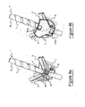
Figures 4a and 4b show two steps of the process of installing the device ofFigure 1 , according to an advantageous embodiment; -
Figure 5 is an axonometric view of an optical branching device according to a second embodiment of the present invention; and -
Figure 6 is an axonometric view of the base of the device ofFigure 5 . -
Figures 1 to 4 show an optical branching device 1 (referred to hereafter as a "device" for the sake of simplicity) according to a first embodiment of the present invention. The drawings are not to scale. - The device 1 comprises a base 2 and a cover 3.
- The base 2 is preferably substantially circular in shape; more specifically, it is in the shape of a circle from which a circular segment with one base has been cut. The base 2 has a
bottom 21 and alateral wall 22 substantially perpendicular to thebottom 21. Thebottom 21 can have an aperture 23, preferably of circular shape, positioned substantially in the centre of thebottom 21. - The base 2 comprises a
central channel 24 and a number oflateral channels bottom 21. - The
central channel 24 is substantially straight and passes through the whole base 2 along its axis of symmetry. Preferably, thecentral channel 24 has a substantially U-shaped cross section. The opposite ends of thecentral channel 24 terminate in respectivefirst recesses first recesses - In the device 1 shown in
Figures 1 to 4 , by way of non-limiting example, the base 2 comprises twolateral channels 25 on one side of thecentral channel 24 and twolateral channels 26 on the opposite side of thecentral channel 24. Thelateral channels central channel 24. Preferably, the intermediate portion of thecentral channel 24 from which thelateral channels central channel 24 from which thelateral channels - The
lateral channels central channel 24 along two oblique directions which are symmetrical with respect to thecentral channel 24. In particular, thelateral channels central channel 24, towards one of thefirst recesses 224b, and, in the transverse direction relative to thecentral channel 24, towards the outside of the base 2. Thus the portion of thecentral channel 24 opposite therecess 224b and thelateral channels - The
lateral channels lateral channel 24. The acute angle is preferably in the range from 30° to 60°. - In an alternative embodiment, the angle formed by the
central channel 24 and each of thelateral channels - In particular, depending on the type of optical fibre used, radii of curvature of the optical fibres in the range from 2 to 20 mm are feasible. If the radius of curvature is in the range from 2 mm to 7 mm, the
lateral channels central channel 24 by an angle of approximately 90°. On the other hand, if the radius of curvature has to be greater than 7 mm, thelateral channels - The portion of
central channel 24 opposite that which forms the Y-shaped (or T-shaped) guide structure with thelateral channels 25, 26 (in other words the portion ofcentral channel 24 adjacent to therecess 224b), and thecorresponding recess 224b, do not project in the longitudinal direction relative to thelateral channels Figure 2 , they do not project beyond the line A, which indicates the maximum extension of thelateral channels - Preferably, the
lateral channels lateral channel central channel 24 terminates in a correspondingsecond recess lateral wall 22 of the base 2. The second recesses 225, 226 are also preferably U-shaped. Thelateral channels lateral channel teeth - The
lateral channels central channel 24 which forms the Y-shaped guide structure with these channels have respective lateral walls whose height relative to the bottom 21 is greater than the height of thelateral wall 22 which surrounds the bottom 21. - The bottom 21 also has at least one housing for a fixing member, located along the
central channel 24. In particular, the bottom 21 has twohousings central channel 24, in other words in the proximity of thefirst recesses housing 27b located in the proximity of therecess 224b is in a non-projecting position relative to thelateral channels 25, 26 (in other words, it does not project beyond the line A shown inFigure 2 ). Preferably, eachhousing central channel 24. - Additionally, the base 2 comprises
fastening elements 28 configured to fix the cover 3 to the base 2. In particular, in the device 1 shown inFigures 1 to 4 , the base 2 comprises twofastening elements 28 located in symmetrical positions on the two sides of thecentral channel 24. Preferably, eachfastening element 28 comprises a protuberance coupled resiliently to the bottom 21 and having a tooth configured to be snap-fastened to the edge of a corresponding fastening hole in the cover 3, as explained more fully below. - Preferably, the overall dimension of the base 2 is in the range from 4 cm to approximately 6 cm. More preferably, the overall dimension is approximately 5 cm.
- The base 2 can advantageously be made in one piece by moulding from a plastic material. The plastic material used can be, for example, ABS (acrylonitrile-butadiene-styrene).
- With reference to
Figure 1 , the cover 3 preferably has a shape and dimensions corresponding to the shape and dimensions of the base 2, in such a way that the cover 3 can be coupled to the base 2 to close the device 1. - In particular, the cover 3 comprises a
central area 31 which is substantially Y-shaped and which is configured to bear on the edges of the lateral walls of thelateral channels central channel 24 which combines with these walls to form the Y-shaped guide structure, when the cover 3 is coupled to the base 2. Thecentral area 31 further comprises twoapertures 311a, 311b. Eachaperture 311a, 311b is positioned in such a way that it is aligned with arespective housing - The cover 3 also comprises two
lateral areas 32 which are depressed relative to thecentral area 31 so as to bear on the edge of thelateral wall 22 when the cover 3 is coupled to the base 2. Eachlateral area 32 comprises acorresponding fastening hole 321. When the cover 3 is placed on the base 2 and pressed on to it, eachfastening hole 321 is engaged by snap-fitting with one of thefastening elements 28 of the base 2, in such a way that the cover 3 is coupled firmly to the base 2. - The cover 3 can advantageously be made from the same material and by the same process as the base 2.
- With reference to
Figures 3a, 3b and 3c , a procedure for installing the branching device 1 according to a first variant will now be described. - It is assumed that the branching device 1 is used in a junction box to extract a number of optical fibres from a riser cable 4 which passes through the junction box.
- The riser cable 4 comprises a
sheath 40 and a number of optical fibres which can be arranged in thesheath 40 in any known arrangement. For example, the optical fibres can be arranged in ribbons, modules, micromodules, or the like, which in turn are housed in thesheath 40. - In order to install the device 1 in the junction box, the operator opens an access window 5 in the
sheath 40 of the portion of the riser cable 4 housed in the junction box. In particular, as shown inFigure 3a , the operator makes a transverse cut and two longitudinal cuts in thesheath 40 and lifts the patch 41 of thesheath 40 delimited by the cuts. The longitudinal cuts preferably have a length of more than 5 cm, and consequently the access window 5 also has a length of more than 5 cm. - The operator also cuts off a portion 42 of the free end of the patch 41. The length of the cut-off portion 42 is preferably in the range from 1 cm to 3 cm. Thus, when the patch 41 is reclosed, the access window 5 is reclosed except for a portion 5a which remains open.
- After opening the access window 5, the operator houses the riser cable 4 in the base 2 (more specifically, in the central channel 24), in such a way that the portion 5a of the access window 5 is entirely housed in the base 2 and the remaining reclosable portion of the access window 5 projects at least partially outside the base, as shown in
Figure 3b . In particular, the reclosable portion of the access window 5 projects at least partially from the base 2 through thefirst recess 224b opposite the portion of thecentral channel 24 which combines with thelateral channels - The operator then fixes the base 2 to the riser cable 4. For this purpose, the operator causes a first fixing member (not shown in the drawings) to be passed around the riser cable 4 and around the
central channel 24 through the pair of apertures in thehousing 27a which is located in the proximity of therecess 224a. The first fixing member can comprise, for example, a plastic wiring strap, a tape, or a metal or plastic catch. The operator then closes the first fixing member which is thus locked in thehousing 27a, in such a way that the base 2 cannot slide axially relative to the riser cable 4. - When the base 2 has been fixed to the riser cable 4, the operator can lift and hold up the patch 41 so as to leave the whole access window 5 exposed, and can then easily identify the optical fibres of the riser cable 4 and extract them from the
sheath 40. - The operator can then insert each extracted optical fibre into a corresponding drop tube 6.
- The operator can then house each drop tube 6 with its optical fibre in one of the
lateral channels teeth lateral channel lateral channels second recess lateral wall 22. - The operator can then reclose the patch 41 so as to reclose the portion of the access window 5 which projects beyond the base 2.
- The operator then completes the fixing of the base 2 to the riser cable 4. For this purpose, the operator causes a second fixing member (not shown in the drawings) to be passed around the riser cable 4 and around the
central channel 24 through the pair of apertures in thehousing 27b which is located in the proximity of therecess 224b. The second fixing member can also comprise, for example, a plastic wiring strap, a tape, or a metal or plastic catch. The operator then closes the second fixing member, which remains locked in thehousing 27b. The second fixing member advantageously keeps the patch 41 closed, thus preventing the accidental reopening of the portion of access window 5 extending outside the base 2. - In an advantageous variant shown in
Figures 4a and 4b , the operator can also wrap one or more strips of tape 7 around the portion of riser cable 4 which comprises the portion of access window 5 which projects from the base 2, in such a way that the whole length of the patch 41 is retained firmly in position. This makes the protection of the access window 5 more effective. - If the patch 41 is inadvertently or intentionally separated from the
sheath 40 and thus leaves the access window 5 permanently exposed, this window can be covered with insulating means such as strips of insulating tape. - The operator then fixes the cover 3 to the base 2 as described above (
Figures 3c and4b ) in order to close the device 1. The ends of the fixing members which fix the base 2 to the riser cable 4 can protrude from the cover 3 through theapertures 311a, 311b of the cover 3. - If the operator wishes to carry out further operations on the optical fibres of the riser cable 4 after the installation described above, he can remove the cover 3 and remove the second fixing member which keeps the patch 41 closed. Thus the operator can lift the patch 41 in order to expose the access window 5 completely, and can then easily carry out the operations of identifying and extracting optical fibres. When these operations are complete, the operator can reclose the access window 5 and the device 1 as described above.
- Advantageously, the device 1 is highly compact and can therefore be installed in the restricted spaces which are typically available in a junction box. This is because the
housing 27b for housing the fixing member which fixes the base 2 to the riser cable 4 is in a non-projecting position relative to thelateral channels recess 224b through which the riser cable 4 emerges above the base 2 is in a non-projecting position relative to thelateral channels - Additionally, the device 1 has the sole function of branching the optical fibres from the riser cable 4, this function being substantially concentrated in the portion 5a of the access window 5 only. The function of protecting the access window is spatially separated from the branching function, and is performed outside the device 1 by the patch 41 which covers the part of the access window 5 which emerges from the base 2. Thus the device 1 can have a longitudinal dimension which is much smaller than the length of the access window 5, and is therefore highly compact.
- With reference to
Figures 5 and6 , a branching device 1' according to a second embodiment of the present invention will now be described. The device 1' comprises abase 200 and acover 300. - The
base 200 comprises a branching portion 2' and a protection portion 2". - The branching portion 2' is substantially identical to the base 2 of the device 1 according to the first embodiment of the present invention. Consequently a detailed description will not be given here. In
Figures 5 and6 , the parts of the branching portion 2' which are similar to those of the base 2 are indicated by the same reference numbers followed by primes. In the device 1' shown inFigures 5 and6 , by way of example the branching portion 2' comprises three lateral channels 25' on one side of the central channel 24' and three lateral channels 26' on the opposite side of the central channel 24'. - The protection portion 2" is joined to the branching portion 2' at the position of the
recess 224b' which terminates the central channel 24' at the end opposite the portion of the central channel 24' which combines with the lateral channels 25', 26' to form the Y-shaped guide structure. Preferably, the protection portion 2" is joined to the branching portion 2' along a weakenedline 29. Thus the protection portion 2" can easily be detached from the branching portion 2' if necessary. - The protection portion 2" is elongate in shape and comprises a bottom 21" and a
lateral wall 22". The bottom 21" has a rectangular shape with rounded corners. At the end opposite the end which is connected to the branching portion 2', thelateral wall 22" has aU-shaped recess 224" aligned with therecesses 224a', 224b' of the lateral wall 22' of the branching portion 2'. The bottom 21" has ahousing 27" for a fixing member in the proximity of therecess 224". Thehousing 27" for a fixing member comprises two adjacent apertures. For practical purposes, the protection portion 2" forms an extension of the central channel 24'. - The
cover 300 comprises a portion 3' for covering the branching and a portion 3" for covering the protection. - The branching cover portion 3' is substantially identical to the cover 3 of the device 1 according to the first embodiment of the present invention. Consequently a detailed description will not be given here. In
Figure 5 , the parts of the branching cover portion 3' which are similar to those of the cover 3 are indicated by the same reference numbers followed by primes. - The protection cover portion 3" is joined to the branching cover portion 3' in such a way that, when the
cover 300 is coupled to thebase 200, the protection cover portion 3" covers the protection portion 2" of thebase 200. Preferably, the protection cover portion 3" is joined to the branching cover portion 3' along a weakened line 39. Thus the protection cover portion 3" can easily be detached from the branching cover portion 3' if necessary. The protection cover portion 3" has anaperture 311 " which is located over thehousing 27" when thecover 300 is coupled to thebase 200. - The
cover 300 has aprotuberance 30 which extends between therecesses 311a' and 311" in such a way that, when thecover 300 is coupled to thebase 200, theprotuberance 30 is located above the central channel 24' and its extension into the protection portion 2". Theprotuberance 30 advantageously provides additional space inside the device 1', in which any excess length of the optical fibres exposed through the access window can be housed. - The procedure for installing the device 1' is described below.
- In order to install the device 1' in a junction box, the operator initially checks whether sufficient free space is available in the junction box to receive the device 1'.
- If this is not the case, the operator can detach the protection portion 2" from the
base 200, and can detach the protection cover portion 3" from thecover 300, along the respective weakenedlines 29, 39. The installation of the device 1' then continues in a similar way to the installation of the device 1 according to the first embodiment. Consequently the detailed description of the installation will not be repeated. - However, if there is sufficient space in the junction box, the operator opens an access window in the sheath of the portion of the riser cable housed in the junction box, in order to expose the optical fibres contained in the cable. According to this second embodiment, the operator can completely detach the cut sheath patch from the cable, in such a way that the access window remains permanently open over its whole length.
- After opening the access window, the operator houses the riser cable in the base 200 (more specifically, in the central channel 24' and in its extension into the protection portion 2"), in such a way that the access window is completely housed in the
base 200. - The operator then fixes the base 200 to the riser cable. For this purpose, the operator causes a first fixing member to be passed around the riser cable and around the extension of the central channel 24' through the pair of apertures in the
housing 27a' which is located in the proximity of therecess 224a'. The operator also causes a second fixing member to be passed around the riser cable and around the extension of the central channel 24' through the pair of apertures in thehousing 27" which is located in the proximity of therecess 224". The operator then closes the first and second fixing members in such a way that each of them remains locked in arespective housing 27a' and 27". Thus the base 200 cannot slide longitudinally relative to the riser cable. - When the
base 200 has been fixed to the riser cable, the operator can easily identify the optical fibres of the riser cable, and if necessary extract them from the sheath, through the access window. - The operator can then insert each extracted optical fibre into a corresponding drop tube.
- The operator can then house each drop tube with its optical fibre in one of the lateral channels 25', 26'. In this second embodiment also, the operator can select the lateral channel 25', 26' in which each drop tube is to be housed, according to the position of the end user's residence relative to the junction box. Additionally, if the lateral channels 25', 26' are of different widths, the selection of the lateral channel may depend on the outside dimension of the tube. Thus each tube emerges from the base 200 through a corresponding second recess 225', 226' in the lateral wall 22'.
- The operator then fixes the
cover 300 to the base 200 in order to close the device 1'. The ends of the fixing members which fix the base 200 to the riser cable can protrude from thecover 300 through theapertures 311a', 311 " of thecover 300. - If, after the installation described above, the operator wishes to carry out a further operation on the optical fibres of the riser cable, he can remove the
cover 300, thus exposing the access window. In this way, the operator can easily carry out the operations of identifying and extracting the optical fibres. When these operations have been completed, the operator can reclose the device 1' as described above. - Advantageously, the device 1' can therefore be installed, if necessary, in the restricted spaces which are typically available in a junction box. This is because the function of branching the optical fibres from the riser cable is performed solely by the branching portion 2', which has a dimension smaller than the length of the access window, while the function of protecting the access window can be performed by the protection portion 2".
- In particular, if sufficient space is available in the junction box, the protection portion 2" is not removed, and the device 1' performs both of the branching and protection functions.
- However, if the space available in the junction box is insufficient, the protection portion 2" is removed in order to make the device 1' more compact. In the second case, the device 1' performs the branching function only, while the function of protecting the access window is implemented outside the device 1' by the sheath patch, which is not detached from the cable, and which can therefore be reclosed on to the access window. In this case, the device is highly compact, since the end of the central channel 24' opposite the end which forms the Y-shaped structure with the lateral channels 25', 26', and the
housing 27b' which receives the fixing member for fixing the base 200 to the cable, do not project beyond thelateral channels
Claims (10)
- An optical branching device (1; 1') suitable for branching optical fibers extracted through an access window (5) cut in a sheath (40) of an optical cable (4), said optical branching device (1; 1') comprising:- a central channel (24; 24') configured to house a portion of said optical cable (4);- at least one lateral channel (25, 26; 25', 26') which radiates from said central channel (25, 26; 25', 26') and which is configured to house at least one of said optical fibers; and- at least one housing (27b; 27b') suitable for receiving a fixing member for fixing said device (1; 1') to said optical cable (4),
wherein said housing (27b; 27b') is in a non-projecting position relative to said lateral channel (25, 26; 25', 26') along a longitudinal direction of said central channel (24; 24'). - The device (1; 1') according to claim 1, wherein said lateral channel (25, 26; 25', 26') diverges by an acute angle from said central channel (24; 24').
- The device (1; 1') according to claim 1 or 2, wherein at least two lateral channels (25, 26; 25', 26') are provided, located on opposite sides of said central channel (24; 24') relative to said longitudinal direction.
- The device (1; 1') according to claim 3, wherein said at least two lateral channels (25, 26; 25', 26') are located at a portion of said access window (5), said portion having a length not greater than 50% of an overall length of said access window (5).
- The device (1; 1') according to any of the preceding claims, wherein said at least one lateral channel (25, 26; 25', 26') has an inner surface with millings (251, 261; 251', 261') projecting towards the interior of the channel.
- The device (1; 1') according to any of the preceding claims, further comprising a base (2; 2') and a cover (3, 3'), said central channel (24; 24') and said at least one lateral channel (25, 26; 25', 26') being arranged on said base (2; 2'), said cover (3, 3') being suitable for being coupled to said base (2, 2') for closing said device (1, 1').
- The device (1, 1') according to any of the preceding claims, further comprising a protection portion (2") connected to said base (2'), said protection portion (2") being an extension of said central channel (24').
- The device (1, 1') according to claim 7, wherein said protection portion (2") is removably connected to said base (2').
- A process for branching optical fibers from an optical cable (4), said process comprising:- cutting an access window (5) in a sheath (40) of an optical cable (4), thereby defining a patch (41) of said sheath (40);- extracting said optical fibers from said optical cable (4) through said access window (5);- arranging said optical fibers so that they divert from a longitudinal direction of said optical cable (4) along a portion (5a) of said access window (5); and- covering at least a further portion of said access window (5) by said patch (41) of said sheath (40).
- The process according to claim 9, wherein said portion (5a) of said access window (5) has a length not greater than 50% of an overall length of said access window (5).
Priority Applications (1)
| Application Number | Priority Date | Filing Date | Title |
|---|---|---|---|
| PL11194825T PL2469315T3 (en) | 2010-12-23 | 2011-12-21 | Optical branching device |
Applications Claiming Priority (1)
| Application Number | Priority Date | Filing Date | Title |
|---|---|---|---|
| ITMI2010A002394A IT1403284B1 (en) | 2010-12-23 | 2010-12-23 | OPTICAL DIRECTION DEVICE |
Publications (2)
| Publication Number | Publication Date |
|---|---|
| EP2469315A1 true EP2469315A1 (en) | 2012-06-27 |
| EP2469315B1 EP2469315B1 (en) | 2019-11-06 |
Family
ID=43737047
Family Applications (1)
| Application Number | Title | Priority Date | Filing Date |
|---|---|---|---|
| EP11194825.3A Active EP2469315B1 (en) | 2010-12-23 | 2011-12-21 | Optical branching device |
Country Status (6)
| Country | Link |
|---|---|
| US (1) | US8615152B2 (en) |
| EP (1) | EP2469315B1 (en) |
| AU (1) | AU2011265463B2 (en) |
| ES (1) | ES2770365T3 (en) |
| IT (1) | IT1403284B1 (en) |
| PL (1) | PL2469315T3 (en) |
Families Citing this family (1)
| Publication number | Priority date | Publication date | Assignee | Title |
|---|---|---|---|---|
| US10998703B1 (en) * | 2020-02-26 | 2021-05-04 | International Business Machines Corporation | Cable routing and bend radius defining tool |
Citations (5)
| Publication number | Priority date | Publication date | Assignee | Title |
|---|---|---|---|---|
| WO2009110177A1 (en) * | 2008-03-07 | 2009-09-11 | Fujikura Ltd. | Optical fiber cable and method of mid-span access thereof |
| WO2009114771A1 (en) * | 2008-03-13 | 2009-09-17 | Adc Telecommunications, Inc. | Method of attachment of a connector to a fiber optic cable |
| WO2009113112A1 (en) * | 2008-03-14 | 2009-09-17 | Prysmian S.P.A. | Method of connecting user devices to optical fibre units contained in an optical cable |
| US20100150504A1 (en) * | 2008-12-11 | 2010-06-17 | Tyco Electronics Corporation | Fiber optic multi dwelling unit deployment appartus and methods for using the same |
| EP2216662A1 (en) * | 2009-02-10 | 2010-08-11 | Tyco Electronics Raychem BVBA | Splice protection device for optical splices and optical fibre cable assembly incorporating same |
-
2010
- 2010-12-23 IT ITMI2010A002394A patent/IT1403284B1/en active
-
2011
- 2011-12-21 EP EP11194825.3A patent/EP2469315B1/en active Active
- 2011-12-21 PL PL11194825T patent/PL2469315T3/en unknown
- 2011-12-21 ES ES11194825T patent/ES2770365T3/en active Active
- 2011-12-22 US US13/335,617 patent/US8615152B2/en active Active
- 2011-12-22 AU AU2011265463A patent/AU2011265463B2/en active Active
Patent Citations (6)
| Publication number | Priority date | Publication date | Assignee | Title |
|---|---|---|---|---|
| WO2009110177A1 (en) * | 2008-03-07 | 2009-09-11 | Fujikura Ltd. | Optical fiber cable and method of mid-span access thereof |
| WO2009114771A1 (en) * | 2008-03-13 | 2009-09-17 | Adc Telecommunications, Inc. | Method of attachment of a connector to a fiber optic cable |
| WO2009113112A1 (en) * | 2008-03-14 | 2009-09-17 | Prysmian S.P.A. | Method of connecting user devices to optical fibre units contained in an optical cable |
| US20100150504A1 (en) * | 2008-12-11 | 2010-06-17 | Tyco Electronics Corporation | Fiber optic multi dwelling unit deployment appartus and methods for using the same |
| EP2216662A1 (en) * | 2009-02-10 | 2010-08-11 | Tyco Electronics Raychem BVBA | Splice protection device for optical splices and optical fibre cable assembly incorporating same |
| US20100232752A1 (en) | 2009-02-10 | 2010-09-16 | Tyco Electronics Raychem Bvba | Splice protection device for optical splices |
Also Published As
| Publication number | Publication date |
|---|---|
| US8615152B2 (en) | 2013-12-24 |
| ITMI20102394A1 (en) | 2012-06-24 |
| IT1403284B1 (en) | 2013-10-17 |
| PL2469315T3 (en) | 2020-06-01 |
| EP2469315B1 (en) | 2019-11-06 |
| US20120163760A1 (en) | 2012-06-28 |
| AU2011265463B2 (en) | 2015-05-28 |
| AU2011265463A1 (en) | 2012-07-12 |
| ES2770365T3 (en) | 2020-07-01 |
Similar Documents
| Publication | Publication Date | Title |
|---|---|---|
| EP2265983B1 (en) | Method of connecting user devices to optical fibre units contained in an optical cable | |
| CN102204049B (en) | hermetic package | |
| CN101836147B (en) | Wavelength division multiplexing module | |
| EP2646866B1 (en) | Fiber organizer and distribution box | |
| US8005333B2 (en) | Tap-off closure systems and methods for using the same | |
| KR101253889B1 (en) | Terminal box for optical cable | |
| US8921693B2 (en) | Distribution cabinet for optical fibre cables | |
| CN101253436A (en) | Housings for communication lines and connectors | |
| EP2455793B1 (en) | Optical transition box | |
| US8428420B2 (en) | Assembly for installing an optical access network | |
| EP2469315B1 (en) | Optical branching device | |
| JP4104513B2 (en) | Optical cable connection closure | |
| ES2655511T3 (en) | Optical Cable Transition Box Assembly | |
| KR101080374B1 (en) | Divergencing set for optical fiber drop cable | |
| US11320617B2 (en) | Connection box and method for connecting optical cables | |
| RU2575476C2 (en) | Surface mount box |
Legal Events
| Date | Code | Title | Description |
|---|---|---|---|
| AK | Designated contracting states |
Kind code of ref document: A1 Designated state(s): AL AT BE BG CH CY CZ DE DK EE ES FI FR GB GR HR HU IE IS IT LI LT LU LV MC MK MT NL NO PL PT RO RS SE SI SK SM TR |
|
| AX | Request for extension of the european patent |
Extension state: BA ME |
|
| PUAI | Public reference made under article 153(3) epc to a published international application that has entered the european phase |
Free format text: ORIGINAL CODE: 0009012 |
|
| 17P | Request for examination filed |
Effective date: 20121220 |
|
| RAP1 | Party data changed (applicant data changed or rights of an application transferred) |
Owner name: PRYSMIAN S.P.A. |
|
| STAA | Information on the status of an ep patent application or granted ep patent |
Free format text: STATUS: EXAMINATION IS IN PROGRESS |
|
| 17Q | First examination report despatched |
Effective date: 20180704 |
|
| GRAP | Despatch of communication of intention to grant a patent |
Free format text: ORIGINAL CODE: EPIDOSNIGR1 |
|
| STAA | Information on the status of an ep patent application or granted ep patent |
Free format text: STATUS: GRANT OF PATENT IS INTENDED |
|
| INTG | Intention to grant announced |
Effective date: 20190528 |
|
| GRAS | Grant fee paid |
Free format text: ORIGINAL CODE: EPIDOSNIGR3 |
|
| GRAA | (expected) grant |
Free format text: ORIGINAL CODE: 0009210 |
|
| STAA | Information on the status of an ep patent application or granted ep patent |
Free format text: STATUS: THE PATENT HAS BEEN GRANTED |
|
| AK | Designated contracting states |
Kind code of ref document: B1 Designated state(s): AL AT BE BG CH CY CZ DE DK EE ES FI FR GB GR HR HU IE IS IT LI LT LU LV MC MK MT NL NO PL PT RO RS SE SI SK SM TR |
|
| REG | Reference to a national code |
Ref country code: GB Ref legal event code: FG4D |
|
| REG | Reference to a national code |
Ref country code: CH Ref legal event code: EP Ref country code: AT Ref legal event code: REF Ref document number: 1199548 Country of ref document: AT Kind code of ref document: T Effective date: 20191115 |
|
| REG | Reference to a national code |
Ref country code: DE Ref legal event code: R096 Ref document number: 602011063169 Country of ref document: DE |
|
| REG | Reference to a national code |
Ref country code: IE Ref legal event code: FG4D |
|
| REG | Reference to a national code |
Ref country code: RO Ref legal event code: EPE |
|
| REG | Reference to a national code |
Ref country code: NL Ref legal event code: FP |
|
| REG | Reference to a national code |
Ref country code: LT Ref legal event code: MG4D |
|
| PG25 | Lapsed in a contracting state [announced via postgrant information from national office to epo] |
Ref country code: GR Free format text: LAPSE BECAUSE OF FAILURE TO SUBMIT A TRANSLATION OF THE DESCRIPTION OR TO PAY THE FEE WITHIN THE PRESCRIBED TIME-LIMIT Effective date: 20200207 Ref country code: NO Free format text: LAPSE BECAUSE OF FAILURE TO SUBMIT A TRANSLATION OF THE DESCRIPTION OR TO PAY THE FEE WITHIN THE PRESCRIBED TIME-LIMIT Effective date: 20200206 Ref country code: SE Free format text: LAPSE BECAUSE OF FAILURE TO SUBMIT A TRANSLATION OF THE DESCRIPTION OR TO PAY THE FEE WITHIN THE PRESCRIBED TIME-LIMIT Effective date: 20191106 Ref country code: LV Free format text: LAPSE BECAUSE OF FAILURE TO SUBMIT A TRANSLATION OF THE DESCRIPTION OR TO PAY THE FEE WITHIN THE PRESCRIBED TIME-LIMIT Effective date: 20191106 Ref country code: FI Free format text: LAPSE BECAUSE OF FAILURE TO SUBMIT A TRANSLATION OF THE DESCRIPTION OR TO PAY THE FEE WITHIN THE PRESCRIBED TIME-LIMIT Effective date: 20191106 Ref country code: BG Free format text: LAPSE BECAUSE OF FAILURE TO SUBMIT A TRANSLATION OF THE DESCRIPTION OR TO PAY THE FEE WITHIN THE PRESCRIBED TIME-LIMIT Effective date: 20200206 Ref country code: PT Free format text: LAPSE BECAUSE OF FAILURE TO SUBMIT A TRANSLATION OF THE DESCRIPTION OR TO PAY THE FEE WITHIN THE PRESCRIBED TIME-LIMIT Effective date: 20200306 Ref country code: LT Free format text: LAPSE BECAUSE OF FAILURE TO SUBMIT A TRANSLATION OF THE DESCRIPTION OR TO PAY THE FEE WITHIN THE PRESCRIBED TIME-LIMIT Effective date: 20191106 |
|
| PG25 | Lapsed in a contracting state [announced via postgrant information from national office to epo] |
Ref country code: IS Free format text: LAPSE BECAUSE OF FAILURE TO SUBMIT A TRANSLATION OF THE DESCRIPTION OR TO PAY THE FEE WITHIN THE PRESCRIBED TIME-LIMIT Effective date: 20200306 Ref country code: HR Free format text: LAPSE BECAUSE OF FAILURE TO SUBMIT A TRANSLATION OF THE DESCRIPTION OR TO PAY THE FEE WITHIN THE PRESCRIBED TIME-LIMIT Effective date: 20191106 Ref country code: RS Free format text: LAPSE BECAUSE OF FAILURE TO SUBMIT A TRANSLATION OF THE DESCRIPTION OR TO PAY THE FEE WITHIN THE PRESCRIBED TIME-LIMIT Effective date: 20191106 |
|
| PG25 | Lapsed in a contracting state [announced via postgrant information from national office to epo] |
Ref country code: AL Free format text: LAPSE BECAUSE OF FAILURE TO SUBMIT A TRANSLATION OF THE DESCRIPTION OR TO PAY THE FEE WITHIN THE PRESCRIBED TIME-LIMIT Effective date: 20191106 |
|
| REG | Reference to a national code |
Ref country code: ES Ref legal event code: FG2A Ref document number: 2770365 Country of ref document: ES Kind code of ref document: T3 Effective date: 20200701 |
|
| PG25 | Lapsed in a contracting state [announced via postgrant information from national office to epo] |
Ref country code: DK Free format text: LAPSE BECAUSE OF FAILURE TO SUBMIT A TRANSLATION OF THE DESCRIPTION OR TO PAY THE FEE WITHIN THE PRESCRIBED TIME-LIMIT Effective date: 20191106 Ref country code: CZ Free format text: LAPSE BECAUSE OF FAILURE TO SUBMIT A TRANSLATION OF THE DESCRIPTION OR TO PAY THE FEE WITHIN THE PRESCRIBED TIME-LIMIT Effective date: 20191106 Ref country code: EE Free format text: LAPSE BECAUSE OF FAILURE TO SUBMIT A TRANSLATION OF THE DESCRIPTION OR TO PAY THE FEE WITHIN THE PRESCRIBED TIME-LIMIT Effective date: 20191106 |
|
| REG | Reference to a national code |
Ref country code: CH Ref legal event code: PL |
|
| REG | Reference to a national code |
Ref country code: DE Ref legal event code: R097 Ref document number: 602011063169 Country of ref document: DE |
|
| REG | Reference to a national code |
Ref country code: AT Ref legal event code: MK05 Ref document number: 1199548 Country of ref document: AT Kind code of ref document: T Effective date: 20191106 |
|
| REG | Reference to a national code |
Ref country code: BE Ref legal event code: MM Effective date: 20191231 |
|
| PG25 | Lapsed in a contracting state [announced via postgrant information from national office to epo] |
Ref country code: MC Free format text: LAPSE BECAUSE OF FAILURE TO SUBMIT A TRANSLATION OF THE DESCRIPTION OR TO PAY THE FEE WITHIN THE PRESCRIBED TIME-LIMIT Effective date: 20191106 Ref country code: SM Free format text: LAPSE BECAUSE OF FAILURE TO SUBMIT A TRANSLATION OF THE DESCRIPTION OR TO PAY THE FEE WITHIN THE PRESCRIBED TIME-LIMIT Effective date: 20191106 Ref country code: SK Free format text: LAPSE BECAUSE OF FAILURE TO SUBMIT A TRANSLATION OF THE DESCRIPTION OR TO PAY THE FEE WITHIN THE PRESCRIBED TIME-LIMIT Effective date: 20191106 |
|
| PLBE | No opposition filed within time limit |
Free format text: ORIGINAL CODE: 0009261 |
|
| STAA | Information on the status of an ep patent application or granted ep patent |
Free format text: STATUS: NO OPPOSITION FILED WITHIN TIME LIMIT |
|
| 26N | No opposition filed |
Effective date: 20200807 |
|
| PG25 | Lapsed in a contracting state [announced via postgrant information from national office to epo] |
Ref country code: LU Free format text: LAPSE BECAUSE OF NON-PAYMENT OF DUE FEES Effective date: 20191221 Ref country code: IE Free format text: LAPSE BECAUSE OF NON-PAYMENT OF DUE FEES Effective date: 20191221 |
|
| PG25 | Lapsed in a contracting state [announced via postgrant information from national office to epo] |
Ref country code: CH Free format text: LAPSE BECAUSE OF NON-PAYMENT OF DUE FEES Effective date: 20191231 Ref country code: BE Free format text: LAPSE BECAUSE OF NON-PAYMENT OF DUE FEES Effective date: 20191231 Ref country code: AT Free format text: LAPSE BECAUSE OF FAILURE TO SUBMIT A TRANSLATION OF THE DESCRIPTION OR TO PAY THE FEE WITHIN THE PRESCRIBED TIME-LIMIT Effective date: 20191106 Ref country code: SI Free format text: LAPSE BECAUSE OF FAILURE TO SUBMIT A TRANSLATION OF THE DESCRIPTION OR TO PAY THE FEE WITHIN THE PRESCRIBED TIME-LIMIT Effective date: 20191106 Ref country code: LI Free format text: LAPSE BECAUSE OF NON-PAYMENT OF DUE FEES Effective date: 20191231 |
|
| PG25 | Lapsed in a contracting state [announced via postgrant information from national office to epo] |
Ref country code: CY Free format text: LAPSE BECAUSE OF FAILURE TO SUBMIT A TRANSLATION OF THE DESCRIPTION OR TO PAY THE FEE WITHIN THE PRESCRIBED TIME-LIMIT Effective date: 20191106 |
|
| PG25 | Lapsed in a contracting state [announced via postgrant information from national office to epo] |
Ref country code: MT Free format text: LAPSE BECAUSE OF FAILURE TO SUBMIT A TRANSLATION OF THE DESCRIPTION OR TO PAY THE FEE WITHIN THE PRESCRIBED TIME-LIMIT Effective date: 20191106 Ref country code: HU Free format text: LAPSE BECAUSE OF FAILURE TO SUBMIT A TRANSLATION OF THE DESCRIPTION OR TO PAY THE FEE WITHIN THE PRESCRIBED TIME-LIMIT; INVALID AB INITIO Effective date: 20111221 |
|
| PG25 | Lapsed in a contracting state [announced via postgrant information from national office to epo] |
Ref country code: TR Free format text: LAPSE BECAUSE OF FAILURE TO SUBMIT A TRANSLATION OF THE DESCRIPTION OR TO PAY THE FEE WITHIN THE PRESCRIBED TIME-LIMIT Effective date: 20191106 |
|
| PG25 | Lapsed in a contracting state [announced via postgrant information from national office to epo] |
Ref country code: MK Free format text: LAPSE BECAUSE OF FAILURE TO SUBMIT A TRANSLATION OF THE DESCRIPTION OR TO PAY THE FEE WITHIN THE PRESCRIBED TIME-LIMIT Effective date: 20191106 |
|
| PGFP | Annual fee paid to national office [announced via postgrant information from national office to epo] |
Ref country code: GB Payment date: 20251229 Year of fee payment: 15 |
|
| PGFP | Annual fee paid to national office [announced via postgrant information from national office to epo] |
Ref country code: IT Payment date: 20251219 Year of fee payment: 15 |
|
| PGFP | Annual fee paid to national office [announced via postgrant information from national office to epo] |
Ref country code: NL Payment date: 20251226 Year of fee payment: 15 Ref country code: FR Payment date: 20251226 Year of fee payment: 15 |
|
| PGFP | Annual fee paid to national office [announced via postgrant information from national office to epo] |
Ref country code: PL Payment date: 20251202 Year of fee payment: 15 |
|
| PGFP | Annual fee paid to national office [announced via postgrant information from national office to epo] |
Ref country code: RO Payment date: 20251205 Year of fee payment: 15 |
|
| PGFP | Annual fee paid to national office [announced via postgrant information from national office to epo] |
Ref country code: ES Payment date: 20260102 Year of fee payment: 15 |
|
| PGFP | Annual fee paid to national office [announced via postgrant information from national office to epo] |
Ref country code: DE Payment date: 20251229 Year of fee payment: 15 |