EP2469229A1 - Method for calibrating an inertial sensor installed in an arbitrary position on board a vehicle, and sensor system of the dynamics of a vehicle able to be installed on board in an arbitrary position - Google Patents
Method for calibrating an inertial sensor installed in an arbitrary position on board a vehicle, and sensor system of the dynamics of a vehicle able to be installed on board in an arbitrary position Download PDFInfo
- Publication number
- EP2469229A1 EP2469229A1 EP11195542A EP11195542A EP2469229A1 EP 2469229 A1 EP2469229 A1 EP 2469229A1 EP 11195542 A EP11195542 A EP 11195542A EP 11195542 A EP11195542 A EP 11195542A EP 2469229 A1 EP2469229 A1 EP 2469229A1
- Authority
- EP
- European Patent Office
- Prior art keywords
- vehicle
- acceleration
- data
- transformation matrix
- acc
- Prior art date
- Legal status (The legal status is an assumption and is not a legal conclusion. Google has not performed a legal analysis and makes no representation as to the accuracy of the status listed.)
- Granted
Links
- 238000000034 method Methods 0.000 title claims abstract description 48
- 239000011159 matrix material Substances 0.000 claims abstract description 72
- 230000009466 transformation Effects 0.000 claims abstract description 24
- 230000001133 acceleration Effects 0.000 claims description 85
- 238000012545 processing Methods 0.000 claims description 18
- 230000005484 gravity Effects 0.000 claims description 11
- 238000001914 filtration Methods 0.000 claims description 9
- 238000005070 sampling Methods 0.000 claims description 6
- 230000008569 process Effects 0.000 claims description 3
- 238000006243 chemical reaction Methods 0.000 description 22
- 238000005259 measurement Methods 0.000 description 20
- 238000004364 calculation method Methods 0.000 description 12
- 238000010586 diagram Methods 0.000 description 9
- 238000009434 installation Methods 0.000 description 7
- 230000006870 function Effects 0.000 description 6
- 230000000875 corresponding effect Effects 0.000 description 5
- 238000004519 manufacturing process Methods 0.000 description 4
- 239000013598 vector Substances 0.000 description 4
- 230000004913 activation Effects 0.000 description 3
- 230000008901 benefit Effects 0.000 description 2
- 238000004891 communication Methods 0.000 description 2
- 230000001360 synchronised effect Effects 0.000 description 2
- 238000012795 verification Methods 0.000 description 2
- 230000003466 anti-cipated effect Effects 0.000 description 1
- 238000013459 approach Methods 0.000 description 1
- 230000006399 behavior Effects 0.000 description 1
- 230000008859 change Effects 0.000 description 1
- 230000000052 comparative effect Effects 0.000 description 1
- 230000002596 correlated effect Effects 0.000 description 1
- 230000001934 delay Effects 0.000 description 1
- 230000003111 delayed effect Effects 0.000 description 1
- 230000001419 dependent effect Effects 0.000 description 1
- 230000000737 periodic effect Effects 0.000 description 1
- 238000000053 physical method Methods 0.000 description 1
- 230000003068 static effect Effects 0.000 description 1
- 238000012546 transfer Methods 0.000 description 1
Images


Classifications
-
- G—PHYSICS
- G01—MEASURING; TESTING
- G01C—MEASURING DISTANCES, LEVELS OR BEARINGS; SURVEYING; NAVIGATION; GYROSCOPIC INSTRUMENTS; PHOTOGRAMMETRY OR VIDEOGRAMMETRY
- G01C25/00—Manufacturing, calibrating, cleaning, or repairing instruments or devices referred to in the other groups of this subclass
- G01C25/005—Manufacturing, calibrating, cleaning, or repairing instruments or devices referred to in the other groups of this subclass initial alignment, calibration or starting-up of inertial devices
Abstract
Description
- The present invention concerns in general the installation and operation of inertial sensors, like for example attitude sensors (gyroscopes) or movement sensors (accelerometers), on board a vehicle.
- More specifically, the invention concerns a calibration method of an inertial attitude or movement sensor installed in an arbitrary position on board a vehicle, according to the preamble of claim 1.
- The invention also concerns a sensor system of the dynamics of a vehicle, according to the preamble of claim 15.
- There is increasingly common use of vehicles that have inertial sensors, such as attitude or acceleration sensors, installed on board, in order to provide accurate indications on the orientation of the vehicle in space and on its movement dynamics. Such devices not only help in the operation of on board driving assistance systems, but are essential for the functionality of other auxiliary systems, including, just to quote one example, systems for tracking and recording the movements of the vehicle used in anti-theft devices or in devices, known by the term black box, for detecting traffic violations or the dynamics of road accidents.
- For this purpose, vehicles can, right from the time of manufacture, include orientation sensor devices, like for example a three-axis gyroscope, and movement sensor devices, like for example a three-axis accelerometer, adapted to precisely detect and measure the attitude and the movement of the vehicle in three dimensions. If these devices are not foreseen at the time of manufacture of the vehicle, they can advantageously be installed at a later time, as aftermarket installations. Both in the first and, above all, in the second case, however, it is not easy in all vehicle models to set positioning constraints of the sensor device, so that its local measuring axes are aligned with the main axes of the vehicle. Constraining the installation of such a sensor device to its correct orientation with respect to the main axes of the vehicle would require an excessive installation time, for accurate installation and for checking that the constraints and the correspondence of the measurements are respected, and in any case it would not preclude possible errors in configuration and measurement such as to jeopardise the correct operation of the system that uses the measurement data of such a sensor.
- For this reason, it is known to foresee the arbitrary arrangement of a sensor device on board a vehicle, in the most convenient location in the engine cavity or in the dashboard, for example in the most easily accessed free seat, and to then carry out its calibration with respect to the axes of the vehicle calculating a conversion matrix (or coordinate transformation matrix, or even rotation matrix) adapted to relate the entities measured in the local reference system with those desired in the main reference system of the vehicle.
-
WO 02/18873 - Disadvantageously, this mixed approach, which reduces the physical measurements to the minimum and fills in the data of the coordinate transformation matrix based on pure mathematical orthogonality relationships existing between the axes of the reference systems, results in the propagation of measurement errors suffered by the six measurements also on the three items of data collected, and causes the risk of concentrating an excessive error on one of the measurement axes, which would significantly compromise the functionality of the application that will be based on the accelerometer data of the vehicle.
- The present invention has the purpose of facilitating the installation of an inertial sensor, such as an attitude or movement sensor, and preferably a tri-axial sensor, on board a vehicle according to an arbitrary orientation, but making it possible to detect attitude or movement data of the vehicle that can be related to the main axes of the vehicle itself, so as to be used for significant applications only in the context of a reference system centred on the vehicle.
- In particular, the present invention has the purpose of providing a satisfactory solution to the problem outlined above, avoiding the drawbacks of the prior art.
- More specifically, the present invention has the purpose of obtaining a method for calibrating an inertial attitude or movement sensor device installed on board a vehicle in an arbitrary position, which is as accurate as possible, with low errors in determining the coefficients of the coordinate transformation matrix between the local reference system of the sensor device and the reference system of the vehicle.
- A further purpose of the invention is to obtain an automatic calibration method that requires simple implementation, minimal computing burdens and low power consumption, favouring speed and accuracy of execution.
- According to the present invention such a purpose is accomplished thanks to a method for calibrating an inertial sensor installed in an arbitrary position on board a vehicle having the characteristics mentioned in claim 1.
- A further subject of the invention is an inertial sensor system able to be installed in an arbitrary position on board a vehicle, as claimed.
- Particular embodiments form the subject of the dependent claims, the content of which should be taken to be an integral part of the present description.
- In brief, the present invention is based on the principle of determining the attitude or the movement of a vehicle referring to a vehicle coordinate system from the attitude or movement data measured by an inertial sensor device installed on board the vehicle in an arbitrary position, and therefore referring to the sensor device's own coordinate system (local reference system), by means of a coordinate transformation matrix.
- The transformation matrix is calculated from the real measured data of the entities indicative of the attitude or movement of the vehicle, obtained from the onboard sensor device, and from corresponding real reference measured data of the vehicle dynamics, referring to the vehicle coordinate system, obtained by different calibrating detector means, for example through a satellite positioning system integrated in the vehicle.
- All of the coefficients of the transformation matrix are calculated by comparison of the aforementioned real measured data, through a number of measurements independent of the entities indicative of the attitude or movement of the vehicle equal to the number of columns of the matrix.
- The error on the coefficients of the transformation matrix calculated from the real measured data is distributed over all of the coefficients by forcing a constraint of orthogonality on the matrix itself, obtaining the rotation matrix closest to the calculated matrix.
- Preferably, the calibration method according to the invention uses real measured reference data of the dynamics of the vehicle obtained through a GPS receiver, advantageously filtered to ensure the optimal dynamic measuring conditions and the accuracy of the signal received.
- Other sources of measured data of the dynamics of the vehicle can be considered as a reference as an alternative to the data of a GPS receiver or of a different positioning system, for example angular speed sensors or differential odometric sensors integrated on board the vehicle for the autonomous measurement of the distances travelled through the rotation measurements of the wheels of the vehicle.
- The essential characteristics of the calibration method according to the invention, described as an example with reference to an accelerometer sensor, can be advantageously applied to calibrate other types of inertial attitude or movement sensors the measuring data of which must refer to one, two or more axes of the vehicle, for example a tri-axial gyroscope.
- Further characteristics and advantages of the invention will be outlined in greater detail in the following detailed description of an embodiment thereof, given as a non-limiting example, with reference to the attached drawings, in which:
-
figure 1 is a schematic representation of a vehicle equipped with an accelerometer device applied in an arbitrary position, in which the main axes of a reference system centred on the vehicle and the axes of a reference system local to the accelerometer device are identified; -
figure 2 is a block diagram of an on-board telematic unit integrating the accelerometer device shown infigure 1 , arranged to carry out a calibration method according to the invention; -
figure 3 is a flow diagram of a calibration method of the accelerometer device shown infigure 1 , according to the invention; -
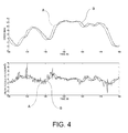
figure 4 shows two diagrams representative of the progress of the speed and of the linear acceleration of the vehicle over time, derived from satellite positioning data of the vehicle, and subjected to filtering; and -
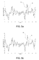
figures 5a and 5b show a comparison on a time scale between the evolution of the reference acceleration data and the acceleration data measured by the on-board device, before and after a synchronisation operation, respectively. - In
figure 1 the letter V generally indicates a vehicle, equipped with a telematic unit T arranged to detect the dynamic conditions of the vehicle, in particular adapted to measure the accelerations undergone by the vehicle while travelling, as a function of the different driving conditions. - The telematic unit T comprises an attitude or movement sensor device S, like for example, but not exclusively, a three-axis accelerometer device, installed in an arbitrary position and adapted to measure the linear and centripetal accelerations undergone by the sensor in the components directed according to the local axes of the device, identified in the figures as x, y, z.
- Again in
figure 1 , the letters X, Y, Z indicate the main axes of the vehicle, commonly identified as longitudinal, transversal and vertical axis, and with respect to which the movements of the vehicle are defined, for example the speeds, accelerations and angles of inclination thereof in all travel conditions. - The telematic unit T can be installed on board the vehicle at the time of manufacture and interfaced with a communication line integrated on board, for example the CAN bus, to transfer the measured data to other processing units of the vehicle. Alternatively, the unit is installed on board the vehicle after its production and it connected to the other processing units through a dedicated communication line, not being possible to access the CAN network.
- As indicated in detail in the block diagram of
figure 2 , as well as the sensor device S the telematic unit comprises an electronic processing unit E, in turn coupled with a GPS receiver, generally indicated with G, or in an equivalent manner with another on-board sensor adapted to acquire reference data of the vehicle dynamics, for carrying out a calibration method that will be described hereafter. Memory modules M1 and M2, typically a random access memory module M1 for storing temporary data and for the computing process and a flash memory module M2 for permanently storing data, are also associated with the processing unit E. - The processing unit E is the calculation unit arranged to acquire acceleration data detected by the sensor device S in its own reference system (x,y,z) and to convert them into the reference system of the vehicle (X,Y,Z) through a predetermined conversion matrix R. The unit E is advantageously arranged to process the inertial data referring to the vehicle, i.e. identifying the orientation of the vehicle in space and on its movement dynamics, in order to obtain a driving assistance system.
- The processing unit E is also arranged, according to the invention, to carry out the calibration of the sensor device S, i.e. to determine the coefficients of the conversion matrix R, on at least one occasion after the installation of the device or, according to a preferred embodiment, to periodically update such coefficients repeatedly, for example according to a predetermined regular frequency or depending on the activation of the driving assistance system that uses the measured data.
- For example, but not exclusively, the telematic unit T can be mounted on board the vehicle and intended to make a system for tracking and recording the movements of the vehicle, for example an accessory system to an anti-theft device or a system for detecting the movements of a vehicle belonging to a fleet, or even a system for detecting traffic violations or the dynamics of road accidents.
- The calibration method is described in detail hereafter with reference to the flow diagram of
figure 3 . - After a
preliminary initialization step 100, the processing unit E instep 110 acquires data indicative of the vehicle dynamics from the GPS receiver G. Such data, typically the evolution of the position data of the vehicle over time, make it possible to determine corresponding reference data of the accelerations of the vehicle along the main axes X, Y, Z. - By using the GPS data the following dynamic conditions of the vehicle can be identified:
- (1) vehicle at rest (zero speed, v ∼= 0);
- (2) vehicle braking or accelerating, without changing direction (linear acceleration different from zero, zero centripetal acceleration component);
- (3) change in direction of the vehicle travelling at constant speed (centripetal acceleration component different from zero);
- (4) other dynamic behaviour, different from the previous ones.
- Conditions (1), (2), (3) make it possible to carry out the calibration method and determine the conversion matrix by combination of the data measured by the accelerometer device and the reference data derived from the positioning data, as will be referred to in detail in the rest of the description. Condition (4) does not allow calibration and, in such a case, the method is automatically suspended, awaiting new usable data.
- The condition (1) of the vehicle at rest can easily be determined also based on just the data of the on-board accelerometer device, by calculating the variance of the measured acceleration data and comparing it with a predetermined threshold, so as to make the calibration method quicker. Alternatively, when the data of the accelerometer device is known in combination with the positioning data the former cooperate to improve the determining of the conditions of the vehicle at rest detected through the latter.
- In fact, in terms of vehicle dynamics, the condition of the vehicle at rest can be considered analogous to the condition in which the vehicle is in constant and uniform motion. Therefore, the condition of the vehicle in motion with constant speed and direction can also be used in the calibration method as an equivalent to condition (1), so as to increase the number of measurements available.
- Since the positioning data, for example the satellite positioning data GPS, does not include acceleration data preliminary processing is necessary to obtain information concerning the vehicle dynamics.
- Firstly, the positioning data is filtered to eliminate invalid data, i.e. the data acquired by the receiver G in uncertain or poor quality positioning conditions. For this reason, the reliability parameters of the positioning data are compared with predetermined thresholds and the data is discarded if at least one of the parameters does not respect the relative threshold. An example indicative of the thresholds of the reliability parameters is given below:
- 3D positioning
- HDOP < 5
- Number of satellites in view > 5
- Minimum CN0 of 3 satellites with stronger signal > 35dBHz
- When the positioning is considered valid, from the positioning data it is possible to work out the speed and direction of travel of the vehicle.
- The linear acceleration AccL can be determined by applying the known expression:

where τ is the GPS sampling period. - The centripetal acceleration Accc is determined from the angular speed (derived from the direction of travel) and from the travelling speed, according to the expression:

where V is the linear speed, expressed in [m/s] and ω is the angular speed, expressed in [rad/s], the latter deriving from the direction of travel (θ) provided by the receiver G according to the relationship:
where τ is the GPS sampling period. - The positioning data is preferably filtered in
step 120 to eliminate the noise considering the dynamic limits of the vehicle. Experimentally, it has been found that a filter that provides a correct balance between performance and complexity (computing cost) is a Butterworth filter of the second order, implementing the relationship:
where Input and Outdata are generically the input and output entities (specifically Input represents the measurements of V and ω, Outdata represents the filtered values of V and ω), and - a(1)=0,0134, a(2)=0,0267, a(3)=0,0134
- b(2)=-1.6475, b(3)=0,7009
- OutData(i) = Input(i);
- OutData(i-1) = Input(i);
- OutData(i-2) = Input(i);
-
Figure 4 shows two diagrams, respectively representative of the progress of the speed and linear acceleration of the vehicle over time, in which the curve indicated with A represents the progress of the entity detected and the curve indicated with B represents the progress of the filtered entity. The benefit of filtering is clear in determining linear acceleration. - At the same time as the acquisition of the positioning data, the processing unit E in
step 110 acquires the vehicle dynamics from the accelerometer device S, referring to the local axes x, y, z. - The acquisition of real acceleration data from the on-board accelerometer device is substantially quicker than the acquisition of reference acceleration data, by about two orders of magnitude (for example the acquisition of data from the accelerometer device occurs every 2.5ms whereas the positioning data is available every 200ms). For this reason, and since consequently the calibration method cannot occur at a higher frequency than the updating frequency of the positioning data, the data of the accelerometer device is processed in advance. Advantageously, by exploiting the sampling speed of 2,5ms it is possible to collect four samples every 10ms and thus average its value and subject the result to noise filtering, in
step 120, according to a technique analogous to the one described earlier in the processing of the positioning data. The coefficients of the Butterworth filter of the second order, implementing the relationship:
obtained experimentally for the accelerometer data are: - a(1)=0,0009, a(2)=0,0019, a(3)=0,0009
- b(2)=-1.9112, b(3)=0,9150
- Finally, the data of the accelerometer device is sampled over a time period of 200ms to obtain the same timing as the data derived from the positioning data.
- However, it should be noted that every filtering operation adds a delay to the propagation of the data being processed. For example, the repeated application of the filter described above to the acceleration data introduces a delay in propagation of the data of about 1 second. Once the measured acceleration data has been acquired from the on-board accelerometer device and the reference acceleration data has been calculated from the positioning data, the two items of data must then be synchronised. Since the data deriving from the GPS information is the result of two filtering operations (filter of the GPS data and additional filtering), whereas the data of the accelerometer device is obtained by sampling in real time, the synchronisation is necessary to take into account the delay in availability of the reference data of the delays introduced by the filters. Since the reference data is necessary to determine the calibration conditions, as will be made clearer hereafter, the real acceleration data is temporarily stored in buffer memory modules of the memory bank M1. The depth of the buffer used to store the data will determine the synchronisation delay applied.
- The diagram of
figure 5a shows a real time comparison on a time scale between the delayed evolution of the reference data deriving from the GPS positioning data (curve indicated with A in the figures) and the anticipated evolution of the real acceleration data (curve indicated with B in the figures). -
Figure 5b shows a comparative diagram between the evolution of the reference data deriving from the GPS positioning data (curve A) and the evolution of the real acceleration data (curve B) after synchronisation through the buffer memory with delay of 1000ms (corresponding to 5 GPS data samples). - Referring once again to the diagram of
figure 3 , once the acquisition of the real acceleration data and of the reference acceleration data has been carried out, advantageously filtered and synchronised, the processing unit E carries out the operations for calculating the coefficients of the conversion matrix. - At level 200 the current dynamic condition of the vehicle is verified, by comparison of the positioning data and the reference acceleration data deriving from it with predetermined threshold values. Specifically, the condition (1) of the vehicle at rest is determined if the following relationships are satisfied:
- GPS Speed < TH.STATIC_SPD
- abs (GPS AccL) < TH.STATIC_ACC
- Preferably, the threshold values are set as follows:
- TH.STATIC_SPD = 0,5 m/s
- TH.STATIC_ACC = 0,7 m/s 2
- The condition (2) of linear acceleration is determined if the following relationships are satisfied:
- GPS Speed > TH.LINEAR_SPD
- abs(GPS AccL) > TH.LINEAR_ACC
- abs(GPSAeec / GPSAeeL) < TH.LIN_RATIO
- Preferably, the threshold values are set as follows:
- TH.LINEAR_SPD = 3 m/s
- THLINEAR_ACC = 1,2 m/s2
- TH.LIN_RATIO = 0,25
- The condition (3) of centripetal acceleration is determined if the following relationships are satisfied:
- GPS Speed > TH. CENTR_SPD
- abs(GPS AccC) > TH.CENTR_ACC_C
- abs(GPS AccL /GPSAccC) < TH. CENTR_RATIO
- Preferably, the threshold values are set as follows:
- TH.CENTR_SPD = 5 m/s
- TH.CENTR_RATIO = 0,25
- THCENTR_ACC_C = 1,3 m/s2
- It should be noted that to determine the dynamic conditions of linear and centripetal acceleration of the vehicle, it is necessary for the latter to travel at a speed greater than a respective threshold, since otherwise the speed and direction measurements made with the help of the GPS receiver would not be reliable.
- The greater contribution of linear or centripetal acceleration is recognised through the calculation of the ratio between the two entities. The threshold value of 0,25 defines a maximum tolerated error of 25% for each measurement.
- If the condition (1) of the vehicle at rest is recognised in the
threshold comparison step 210, the method moves on to step 310 in which the contribution of the gravity acceleration on the accelerometer device is determined. This step is very important, since the contribution of the gravity acceleration must be known for the calibration calculation in the linear and centripetal acceleration conditions. Therefore, it is necessary to acquire a predetermined minimum number of real measured data samples with the vehicle at rest, for example 50, in order to be able to also carry out the calibrations in the conditions of the vehicle accelerating. - If the outcome of the verification of the dynamic conditions of the vehicle in step 200 is the recognition of a linear acceleration (or deceleration) in the
threshold comparison step 220, the method moves on to step 320 in which it is verified whether the calculation of the contribution of the gravity acceleration on the accelerometer device has been completed. - Similarly, if the outcome of the verification of the dynamic conditions of the vehicle in step 200 is the recognition of a condition of centripetal acceleration (or deceleration) in
threshold comparison step 230, the method moves on to step 330 in which it is verified whether the calculation of the contribution of the gravity acceleration on the accelerometer device has been completed. - Once the contribution of the gravity acceleration has been calculated, as a function of the current dynamic condition the processing unit E in level 400 updates the elements of the conversion matrix correlated to it.
- The structure of the real conversion matrix R is represented below:

with a notation of the elements that makes it possible to identify each of them as a function of the dynamic calibration condition during which it is determined (L = linear acceleration, C = centripetal acceleration, S = static condition or vehicle at rest) and the axis of the local reference system (x, y, z) to which it refers. - For example, Lx is the element of the matrix determined in the dynamic condition of linear acceleration of the vehicle, and relative to the measurement of the accelerometer device along the axis X.
- The conversion expression between the accelerations vector measured in the local reference system of the accelerometer (axs, ays, azs) and the accelerations vector in the reference system of the vehicle (aXv, aYv, aZv) is as follows:

- Preferably, in each iteration of the calibration method the values of the elements of the matrix are attributed by applying a filtering operation that takes into account the number of previous measuring events, for example according to the expression:

value 0 in step 100) is increased: nstep = nstep +1 - This filtering operation is ― in the opinion of the inventors ― the best compromise between performance, simple implementation and low memory and calculation needs. In order to avoid slowing down the calculations as the number of measurements increases, and at the same time to avoid attributing excessively low weights to new measurements, the filter is preferably limited to a minimum weight of 1/400.
- In the dynamic condition of the vehicle at rest, in
step 410 the processing unit updates the elements of the third column of the conversion matrix Sx, Sy, Sz as a function of the average values of the real measured data Acc_x, Acc_y, Acc_z of the accelerometer device, and of the values of the elements of the matrix calculated in the previous iteration, according to the relationships:


where


and the values of the contributions of the gravity acceleration as:


- In the dynamic condition of the vehicle subject to linear accelerations, in
step 420 the processing unit updates the elements of the first column of the conversion matrix Lx, Ly, Lz as a function of the average values of the real measured data Acc_x, Acc_y, Acc_z of the accelerometer device, and of the contributions of gravity calculated, according to the relationships:


where


and


in which GPS_Acc is the linear acceleration value derived from the GPS positioning data. - In the dynamic condition of the vehicle subject to centripetal acceleration, in
step 430 the processing unit updates the elements of the second column of the conversion matrix Cx, Cy, Cz as a function of the average values of the real measured data Acc_x, Acc_y, Acc_z of the accelerometer device, and of the calculated contributions of gravity, according to the relationships:


where


and


in which GPS_Acc_C is the centripetal acceleration value deriving from the GPS positioning data. - If the calibration method is not complete, i.e. all of the elements of the conversion matrix have not been calculated, or else if the calculation of the contributions of the gravity acceleration is not complete, for which reason the processing unit cannot proceed to calculate the elements of the matrix corresponding to the operative conditions in which the vehicle is subjected to linear or centripetal acceleration, there is another iteration of a new cycle of acquiring the positioning data, measuring the accelerometer data, synchronising and calculating the matrix elements, from
steps - The calibration method is considered adequately completed in
step 500 when the number of samples considered for each dynamic condition is greater than a predetermined threshold value, for example 300. Of course, a different completeness threshold can be defined. Where the threshold value is greater, the time necessary to carry out the calibration will also be longer, but the result will be more accurate. - When calibration is complete, it is possible to carry out a refinement of the conversion matrix by once again carrying out the calibration method and periodically updating the values of the elements of the matrix.
- The conversion matrix R obtained at the end of the calibration method based on the data acquired is a real conversion matrix, the elements of which are affected by measuring errors, for which reason it does not respect the requirement of orthogonality of the line vectors and of the column vectors. The conversion matrix is therefore subjected to orthogonalisation in
step 600, i.e. there is a calculation of the orthogonal rotation matrix closest to the conversion matrix calculated through the measurements. - Briefly, an orthogonal matrix is defined as a matrix the transpose of which is equal to the inverse (QTQ = QQT = I or in alternative notation QT = Q-1). An additional constraint for the rotation matrix is that the determinant is equal to one: Det(Q)=1.
- In order to determine the orthogonal rotation matrix Ro closest to the calculated real conversion matrix R, the following formula is applied:

- The orthogonal conversion matrix closest to the above calculated real conversion matrix advantageously makes it possible to redistribute the measuring errors suffered by the real conversion matrix over the entire orthogonal matrix, i.e. over all of the elements of the rotation matrix, and to obtain a rotation matrix.
- Advantageously, since the calculation of the orthogonal matrix is quite a difficult task in terms of computing for the processing unit E, it may not be carried out for each periodic update of the conversion matrix, but only periodically, for example every 150 updates.
- With the calculation of the orthogonal rotation matrix the calibration method ends and the matrix is saved inside the non-volatile memory M2.
- The calibration method described can be carried out just once when the vehicle starts or upon activation of the driving assistance system that integrates the accelerometer measurements, or it can be carried out cyclically after the vehicle starts or after the activation of the driving assistance system. In this case, it is foreseen for there to be a first quick rough calibration cycle and subsequent fine calibration cycles.
- Advantageously, as can be understood from reading the description above, the calibration method according to the invention leads to the generation of a coordinate transformation matrix between the local reference system of the sensor device and the reference system of the vehicle in which every coefficient is determined with greater accuracy with respect to the prior art.
- Of course, without affecting the principle of the invention, the embodiments and the details can be widely varied with respect to what has been described and illustrated purely as non-limiting examples, without for this reason departing from the scope of protection of the invention defined by the attached claims.
Claims (15)
- A method for calibrating an inertial sensor device (S) installed in an arbitrary position on board a vehicle (V) and adapted to detect at least an entity indicative of the vehicle dynamics along at least one direction of a local reference coordinate system (x,y,z), comprising the steps of:- acquiring (110), by means of said onboard sensor device (S), at predetermined measuring times, real measured data indicative of the vehicle dynamics in said local coordinate system (x,y,z);- acquiring (110), by means of calibrating detector means (G) different from said onboard sensor device (S), at sampling times coinciding with said measuring times, reference measured data indicative of the vehicle dynamics in a vehicle coordinate system (X,Y,Z);- generating (200-500) a coordinate transformation matrix (R), adapted to correlate the entities measured in the local coordinate system (x,y,z) with corresponding entities in the vehicle coordinate system (X,Y,Z),
characterised in that all the elements of the transformation matrix (R) are computed by comparing (410, 420, 430) a plurality of real measured data acquired by the onboard sensor device (S) with a corresponding plurality of reference measured data obtained in a plurality of different driving conditions,
wherein said plurality of measured data comprise a quantity of items of data equal to the quantity of elements of the transformation matrix (R); and
in that the value of each element of the transformation matrix (R) is adjusted by forcing a constraint of orthogonality (600), so as to obtain the orthogonal transformation matrix (Ro) which is closest to the transformation matrix (R) obtained based on the measured data. - A method according to Claim 1, wherein said calibrating detector means comprise a satellite positioning system (G).
- A method according to Claim 1, wherein said calibrating detector means comprise odometric sensors integrated on board the vehicle (V).
- A method according to any one of the preceding claims, characterised in that it is carried out if the travelling speed of the vehicle (V) is greater than a minimum threshold speed.
- A method according to any one of the preceding claims, comprising periodically updating the value of each element of the transformation matrix (R) and computing the orthogonal matrix (Ro) after a predetermined number of updates of the value of the elements of the transformation matrix (R).
- A method according to any one of the preceding claims, wherein computing the value of the elements of the transformation matrix (R) at each iteration of the calibration process comprise applying a filtering operation taking into account the number of previous measuring events, according to the expression:

where Output is the current value of the dynamic entity under consideration, New_Value is the measured value of the dynamic entity under consideration and n step is a measuring counter. - A method according to any one of the preceding claims, wherein in order to determine the orthogonal transformation matrix (Ro) which is the closest to the transformation matrix (R) obtained on the basis of the measured data the following formula is applied:

- A method according to any one of the preceding claims, characterised in that it is applied for calibrating a tri-axial accelerometer sensor.
- A method according to Claim 8, wherein the measured data indicative of the vehicle dynamics are linear and centripetal acceleration data detected in the dynamic conditions of: vehicle at rest or moving at a constant and uniform speed; vehicle linearly accelerating or decelerating; vehicle changing its travel direction at a constant speed.
- A method according to Claim 9, wherein the dynamic condition of vehicle at rest is determined (210) when the detected travelling speed of the vehicle is lower than a first speed threshold and the detected linear acceleration is, in its absolute value, lower than a first linear acceleration threshold.
- A method according to Claim 9, wherein the dynamic condition of linear acceleration is determined (220) when the detected travelling speed of the vehicle is greater than a second speed threshold, the detected linear acceleration is, in its absolute value, greater than a second linear acceleration threshold and the absolute ratio between the detected centripetal acceleration and the detected linear acceleration is lower than a comparison threshold value.
- A method according to Claim 9, wherein the dynamic condition of centripetal acceleration is determined (230) when the detected travelling speed of the vehicle is greater than a third speed threshold, the detected centripetal acceleration is, in its absolute value, greater than a first centripetal acceleration threshold and the absolute ratio between the detected linear acceleration and the detected centripetal acceleration is lower than said comparison threshold value.
- A method according to any one of the preceding claims, wherein the calibration acceleration data detected at a plurality of subsequent sampling times and the acceleration data measured at a plurality of subsequent measuring times are processed by applying a Butterworth filter of the second order implementing the relationship:

where Input and Outdata are the dynamic input and output entities, respectively. - A method according to any one of the preceding claims, including determining (310) the contribution of the gravity acceleration in the condition of vehicle at rest from a predetermined minimum number of real measured data samples, the computing of the elements of the transformation matrix as a function of the measured data obtained in the driving conditions of linear and centripetal acceleration being carried out by taking into consideration (320, 330) the contribution of the gravity acceleration thus determined.
- A sensor system of the vehicle dynamics, capable of being installed at an arbitrary position on board the vehicle (V) and comprising an inertial sensor device (S) adapted to detect at least an entity indicative of the vehicle dynamics along at least a direction of a local reference coordinate system (x,y,z),
characterized in that it includes processing means (E) arranged for acquiring the data detected by the sensor device (S) in its reference system (x,y,z) and for converting said data in a vehicle reference system (X,Y,Z) through a coordinate transformation matrix (R) computed by a calibration method according to any one of claims 1 to 14.
Applications Claiming Priority (1)
| Application Number | Priority Date | Filing Date | Title |
|---|---|---|---|
| ITTO2010A001062A IT1403430B1 (en) | 2010-12-24 | 2010-12-24 | CALIBRATION PROCEDURE OF AN INERTIAL SENSOR ASSEMBLED IN AN ARBITRARY POSITION ON THE VEHICLE OF A VEHICLE, AND A SENSOR SYSTEM OF THE DYNAMICS OF A VEHICLE MOUNTED ON BOARD IN AN ARBITRARY POSITION |
Publications (2)
| Publication Number | Publication Date |
|---|---|
| EP2469229A1 true EP2469229A1 (en) | 2012-06-27 |
| EP2469229B1 EP2469229B1 (en) | 2013-11-20 |
Family
ID=43737450
Family Applications (1)
| Application Number | Title | Priority Date | Filing Date |
|---|---|---|---|
| EP11195542.3A Active EP2469229B1 (en) | 2010-12-24 | 2011-12-23 | Method for calibrating an inertial sensor installed in an arbitrary position on board a vehicle, and sensor system of the dynamics of a vehicle able to be installed on board in an arbitrary position |
Country Status (4)
| Country | Link |
|---|---|
| US (1) | US8825274B2 (en) |
| EP (1) | EP2469229B1 (en) |
| IT (1) | IT1403430B1 (en) |
| RU (1) | RU2591018C2 (en) |
Cited By (8)
| Publication number | Priority date | Publication date | Assignee | Title |
|---|---|---|---|---|
| WO2014145409A1 (en) * | 2013-03-15 | 2014-09-18 | Cambridge Mobile Telematics | Inference of vehicular trajectory characteristics with personal mobile devices |
| CN104613980A (en) * | 2014-12-19 | 2015-05-13 | 北京航天时代激光导航技术有限责任公司 | A detection system for field comprehensive performance of airborne model laser inertial navigation |
| CN105387874A (en) * | 2015-12-14 | 2016-03-09 | 中国科学院长春光学精密机械与物理研究所 | Ship-borne high-precision star sensor setting angle calibrating method |
| CN107246883A (en) * | 2017-08-07 | 2017-10-13 | 上海航天控制技术研究所 | A kind of Rotating Platform for High Precision Star Sensor installs the in-orbit real-time calibration method of matrix |
| CN108139212A (en) * | 2015-10-15 | 2018-06-08 | 三菱电机株式会社 | Positioning device and localization method |
| IT201600127830A1 (en) * | 2016-12-19 | 2018-06-19 | Magneti Marelli Spa | Verification procedure of the installation of a device mounted on a vehicle, and relative system. |
| CN109470272A (en) * | 2018-12-05 | 2019-03-15 | 中国科学院长春光学精密机械与物理研究所 | A kind of scaling method of IMU measuring basis |
| WO2019085526A1 (en) * | 2017-11-03 | 2019-05-09 | 北京凌宇智控科技有限公司 | Three-dimensional space-oriented positioning correcting method, combined positioning method and device |
Families Citing this family (21)
| Publication number | Priority date | Publication date | Assignee | Title |
|---|---|---|---|---|
| US20130006674A1 (en) | 2011-06-29 | 2013-01-03 | State Farm Insurance | Systems and Methods Using a Mobile Device to Collect Data for Insurance Premiums |
| US10977601B2 (en) | 2011-06-29 | 2021-04-13 | State Farm Mutual Automobile Insurance Company | Systems and methods for controlling the collection of vehicle use data using a mobile device |
| US9052250B1 (en) | 2012-05-04 | 2015-06-09 | The United States Of America As Represented By The Administrator Of The National Aeronautics And Space Administration | Method of calibrating a force balance |
| US10285141B1 (en) * | 2012-09-19 | 2019-05-07 | Safeco Insurance Company Of America | Data synchronization across multiple sensors |
| US9096188B2 (en) * | 2013-03-22 | 2015-08-04 | General Motors Llc | Mounting sensor and aftermarket device equipped with mounting sensor |
| US8954204B2 (en) | 2013-03-22 | 2015-02-10 | General Motors Llc | Collision sensor, collision sensing system, and method |
| US10078099B2 (en) | 2014-06-24 | 2018-09-18 | Truemotion, Inc. | Methods and systems for aligning a mobile device to a vehicle |
| WO2016014826A1 (en) * | 2014-07-24 | 2016-01-28 | Gentex Corporation | Accelerometer integrated with display device |
| EP3021289B1 (en) | 2014-11-10 | 2020-01-15 | Magneti Marelli S.p.A. | Telematic box device for auto-vehicles |
| EP3021290B1 (en) | 2014-11-10 | 2020-01-01 | Magneti Marelli S.p.A. | Telematic box device for motor vehicles |
| US20160161944A1 (en) * | 2014-12-05 | 2016-06-09 | Charles A. Leonard | Vehicle leveling systems, devices and methods and computer program products for leveling vehicles using smart devices |
| US10067157B2 (en) | 2015-05-07 | 2018-09-04 | Truemotion, Inc. | Methods and systems for sensor-based vehicle acceleration determination |
| US10235817B2 (en) * | 2015-09-01 | 2019-03-19 | Ford Global Technologies, Llc | Motion compensation for on-board vehicle sensors |
| CN106382946B (en) * | 2016-09-14 | 2019-07-09 | 邹红斌 | Parameter calibrating method and device |
| US11041877B2 (en) * | 2016-12-20 | 2021-06-22 | Blackberry Limited | Determining motion of a moveable platform |
| RU179360U1 (en) * | 2017-10-25 | 2018-05-11 | Федеральное государственное автономное образовательное учреждение высшего образования "Национальный исследовательский университет "Московский институт электронной техники" | MEASURING STAND FOR DETERMINING CHARACTERISTICS OF ORIENTATION SENSOR |
| JP6870635B2 (en) | 2018-03-08 | 2021-05-12 | セイコーエプソン株式会社 | Inertial measurement units, mobiles, portable electronic devices, and electronic devices |
| DE102019206996A1 (en) * | 2019-05-14 | 2020-11-19 | Volkswagen Aktiengesellschaft | Method for embedding local sensor data in a card |
| CN112248940B (en) * | 2020-08-27 | 2022-03-29 | 清华大学 | Sensor arrangement resolving method and system for vehicle body attitude control |
| CN111982158B (en) * | 2020-10-21 | 2022-10-11 | 蘑菇车联信息科技有限公司 | Inertial measurement unit calibration method and device |
| CN113091769A (en) * | 2021-03-30 | 2021-07-09 | Oppo广东移动通信有限公司 | Attitude calibration method and device, storage medium and electronic equipment |
Citations (2)
| Publication number | Priority date | Publication date | Assignee | Title |
|---|---|---|---|---|
| WO2002018873A2 (en) * | 2000-09-01 | 2002-03-07 | Magellan Dis, Inc. | Calibration of multi-axis accelerometer in vehicle navigation system using gps data |
| WO2009006341A1 (en) * | 2007-06-28 | 2009-01-08 | Sirf Technology Holdings, Inc. | Compensation for mounting misalignment of a navigation device |
Family Cites Families (8)
| Publication number | Priority date | Publication date | Assignee | Title |
|---|---|---|---|---|
| DE3917611A1 (en) * | 1989-05-31 | 1990-12-06 | Deutsche Forsch Luft Raumfahrt | METHOD FOR CALIBRATING AN ACCELERATOR |
| US5898390A (en) * | 1995-09-14 | 1999-04-27 | Zexel Corporation | Method and apparatus for calibration of a distance sensor in a vehicle navigation system |
| US5828585A (en) * | 1997-01-17 | 1998-10-27 | Delco Electronics Corporation | Vehicle speed signal calibration |
| EP1207371B1 (en) * | 2000-11-16 | 2007-01-10 | STMicroelectronics S.r.l. | Automatic calibration of a micro-mechanical sensor |
| US6801855B1 (en) * | 2002-06-28 | 2004-10-05 | Garmin Ltd. | Systems and methods with integrated GPS and dead reckoning capabilities |
| RU2269813C2 (en) * | 2004-03-10 | 2006-02-10 | ЗАО "Газприборавтоматикасервис" | Method for calibrating parameters of platform-less inertial measuring module |
| CA2646480A1 (en) * | 2006-04-13 | 2007-10-25 | Tiax Llc | Sensor system |
| RU2376607C1 (en) * | 2008-09-12 | 2009-12-20 | Учреждение Российской академии наук Институт геоэкологии им. Е.М. Сергеева РАН (ИГЭ РАН) | Three-axis accelerometre |
-
2010
- 2010-12-24 IT ITTO2010A001062A patent/IT1403430B1/en active
-
2011
- 2011-12-23 RU RU2011152911/08A patent/RU2591018C2/en active
- 2011-12-23 US US13/336,034 patent/US8825274B2/en active Active
- 2011-12-23 EP EP11195542.3A patent/EP2469229B1/en active Active
Patent Citations (2)
| Publication number | Priority date | Publication date | Assignee | Title |
|---|---|---|---|---|
| WO2002018873A2 (en) * | 2000-09-01 | 2002-03-07 | Magellan Dis, Inc. | Calibration of multi-axis accelerometer in vehicle navigation system using gps data |
| WO2009006341A1 (en) * | 2007-06-28 | 2009-01-08 | Sirf Technology Holdings, Inc. | Compensation for mounting misalignment of a navigation device |
Cited By (12)
| Publication number | Priority date | Publication date | Assignee | Title |
|---|---|---|---|---|
| WO2014145409A1 (en) * | 2013-03-15 | 2014-09-18 | Cambridge Mobile Telematics | Inference of vehicular trajectory characteristics with personal mobile devices |
| US9228836B2 (en) | 2013-03-15 | 2016-01-05 | Cambridge Mobile Telematics | Inference of vehicular trajectory characteristics with personal mobile devices |
| CN104613980A (en) * | 2014-12-19 | 2015-05-13 | 北京航天时代激光导航技术有限责任公司 | A detection system for field comprehensive performance of airborne model laser inertial navigation |
| CN104613980B (en) * | 2014-12-19 | 2019-08-09 | 北京航天时代激光导航技术有限责任公司 | A kind of airborne model laser inertial outfield comprehensive performance detecting system |
| CN108139212A (en) * | 2015-10-15 | 2018-06-08 | 三菱电机株式会社 | Positioning device and localization method |
| CN108139212B (en) * | 2015-10-15 | 2021-07-09 | 三菱电机株式会社 | Positioning device and positioning method |
| CN105387874A (en) * | 2015-12-14 | 2016-03-09 | 中国科学院长春光学精密机械与物理研究所 | Ship-borne high-precision star sensor setting angle calibrating method |
| IT201600127830A1 (en) * | 2016-12-19 | 2018-06-19 | Magneti Marelli Spa | Verification procedure of the installation of a device mounted on a vehicle, and relative system. |
| EP3336488A1 (en) | 2016-12-19 | 2018-06-20 | Magneti Marelli S.p.A. | Method of verification of the installation of an apparatus mounted on board a vehicle, and related system |
| CN107246883A (en) * | 2017-08-07 | 2017-10-13 | 上海航天控制技术研究所 | A kind of Rotating Platform for High Precision Star Sensor installs the in-orbit real-time calibration method of matrix |
| WO2019085526A1 (en) * | 2017-11-03 | 2019-05-09 | 北京凌宇智控科技有限公司 | Three-dimensional space-oriented positioning correcting method, combined positioning method and device |
| CN109470272A (en) * | 2018-12-05 | 2019-03-15 | 中国科学院长春光学精密机械与物理研究所 | A kind of scaling method of IMU measuring basis |
Also Published As
| Publication number | Publication date |
|---|---|
| ITTO20101062A1 (en) | 2012-06-25 |
| EP2469229B1 (en) | 2013-11-20 |
| RU2591018C2 (en) | 2016-07-10 |
| US8825274B2 (en) | 2014-09-02 |
| US20120330497A1 (en) | 2012-12-27 |
| IT1403430B1 (en) | 2013-10-17 |
| RU2011152911A (en) | 2013-06-27 |
Similar Documents
| Publication | Publication Date | Title |
|---|---|---|
| EP2469229B1 (en) | Method for calibrating an inertial sensor installed in an arbitrary position on board a vehicle, and sensor system of the dynamics of a vehicle able to be installed on board in an arbitrary position | |
| EP0789223B1 (en) | Movement detector | |
| EP3264036B1 (en) | System for and method of determining angular position of a vehicle | |
| US20200393491A1 (en) | Systems and Methods for 3-Axis Accelerometer Calibration with Vertical Sample Buffers | |
| US8494710B2 (en) | System and method for identifying a spatial relationship for use in calibrating accelerometer data | |
| EP1722239B1 (en) | Apparatus and method for measuring speed of a moving object | |
| US8731769B2 (en) | Inertial sensor calibration method for vehicles and device therefor | |
| US10466269B2 (en) | Systems and methods for low latency 3-axis accelerometer calibration | |
| EP3336488B9 (en) | Method of verification of the installation of an apparatus mounted on board a vehicle, and related system | |
| US20090005985A1 (en) | GPS-based in-vehicle sensor calibration algorithm | |
| US20100019963A1 (en) | Vehicular navigation and positioning system | |
| CN103930312A (en) | Sensor system comprising a fusion filter for common signal processing | |
| CN109917440B (en) | Combined navigation method, system and vehicle | |
| CN102096087A (en) | GPS-enhanced vehicle velocity estimation | |
| EP2325607A1 (en) | Vehicle estimate navigation appartus, vehicle estimate navigation method, and vehicle estimate navigation program | |
| MX2007012296A (en) | Control system for vehicles. | |
| KR20190040818A (en) | 3D vehicular navigation system using vehicular internal sensor, camera, and GNSS terminal | |
| WO2009025998A1 (en) | Vehicle safety system including accelerometers | |
| EP2985606A1 (en) | Speed calculation device and speed calculation method | |
| US9605958B2 (en) | Method and device for determining the inclined position of a vehicle | |
| CN104169723B (en) | Inertial sensor enhancement | |
| CN109254172B (en) | Position calibration method and device of vehicle acceleration sensor and vehicle control equipment | |
| Huttner et al. | Offset and misalignment estimation for the online calibration of an MEMS-IMU using FIR-filter modulating functions | |
| CN113985466A (en) | Combined navigation method and system based on pattern recognition | |
| Oh et al. | Dynamic sensor zeroing algorithm of 6D IMU mounted on ground vehicles |
Legal Events
| Date | Code | Title | Description |
|---|---|---|---|
| 17P | Request for examination filed |
Effective date: 20120323 |
|
| AK | Designated contracting states |
Kind code of ref document: A1 Designated state(s): AL AT BE BG CH CY CZ DE DK EE ES FI FR GB GR HR HU IE IS IT LI LT LU LV MC MK MT NL NO PL PT RO RS SE SI SK SM TR |
|
| AX | Request for extension of the european patent |
Extension state: BA ME |
|
| PUAI | Public reference made under article 153(3) epc to a published international application that has entered the european phase |
Free format text: ORIGINAL CODE: 0009012 |
|
| GRAP | Despatch of communication of intention to grant a patent |
Free format text: ORIGINAL CODE: EPIDOSNIGR1 |
|
| INTG | Intention to grant announced |
Effective date: 20130613 |
|
| GRAS | Grant fee paid |
Free format text: ORIGINAL CODE: EPIDOSNIGR3 |
|
| GRAA | (expected) grant |
Free format text: ORIGINAL CODE: 0009210 |
|
| AK | Designated contracting states |
Kind code of ref document: B1 Designated state(s): AL AT BE BG CH CY CZ DE DK EE ES FI FR GB GR HR HU IE IS IT LI LT LU LV MC MK MT NL NO PL PT RO RS SE SI SK SM TR |
|
| REG | Reference to a national code |
Ref country code: GB Ref legal event code: FG4D |
|
| REG | Reference to a national code |
Ref country code: CH Ref legal event code: EP |
|
| REG | Reference to a national code |
Ref country code: AT Ref legal event code: REF Ref document number: 641899 Country of ref document: AT Kind code of ref document: T Effective date: 20131215 |
|
| REG | Reference to a national code |
Ref country code: IE Ref legal event code: FG4D |
|
| REG | Reference to a national code |
Ref country code: DE Ref legal event code: R096 Ref document number: 602011003852 Country of ref document: DE Effective date: 20140116 |
|
| REG | Reference to a national code |
Ref country code: NL Ref legal event code: VDEP Effective date: 20131120 |
|
| REG | Reference to a national code |
Ref country code: AT Ref legal event code: MK05 Ref document number: 641899 Country of ref document: AT Kind code of ref document: T Effective date: 20131120 |
|
| REG | Reference to a national code |
Ref country code: LT Ref legal event code: MG4D |
|
| PG25 | Lapsed in a contracting state [announced via postgrant information from national office to epo] |
Ref country code: LT Free format text: LAPSE BECAUSE OF FAILURE TO SUBMIT A TRANSLATION OF THE DESCRIPTION OR TO PAY THE FEE WITHIN THE PRESCRIBED TIME-LIMIT Effective date: 20131120 Ref country code: HR Free format text: LAPSE BECAUSE OF FAILURE TO SUBMIT A TRANSLATION OF THE DESCRIPTION OR TO PAY THE FEE WITHIN THE PRESCRIBED TIME-LIMIT Effective date: 20131120 Ref country code: SE Free format text: LAPSE BECAUSE OF FAILURE TO SUBMIT A TRANSLATION OF THE DESCRIPTION OR TO PAY THE FEE WITHIN THE PRESCRIBED TIME-LIMIT Effective date: 20131120 Ref country code: FI Free format text: LAPSE BECAUSE OF FAILURE TO SUBMIT A TRANSLATION OF THE DESCRIPTION OR TO PAY THE FEE WITHIN THE PRESCRIBED TIME-LIMIT Effective date: 20131120 Ref country code: NL Free format text: LAPSE BECAUSE OF FAILURE TO SUBMIT A TRANSLATION OF THE DESCRIPTION OR TO PAY THE FEE WITHIN THE PRESCRIBED TIME-LIMIT Effective date: 20131120 Ref country code: NO Free format text: LAPSE BECAUSE OF FAILURE TO SUBMIT A TRANSLATION OF THE DESCRIPTION OR TO PAY THE FEE WITHIN THE PRESCRIBED TIME-LIMIT Effective date: 20140220 Ref country code: IS Free format text: LAPSE BECAUSE OF FAILURE TO SUBMIT A TRANSLATION OF THE DESCRIPTION OR TO PAY THE FEE WITHIN THE PRESCRIBED TIME-LIMIT Effective date: 20140320 |
|
| PG25 | Lapsed in a contracting state [announced via postgrant information from national office to epo] |
Ref country code: ES Free format text: LAPSE BECAUSE OF FAILURE TO SUBMIT A TRANSLATION OF THE DESCRIPTION OR TO PAY THE FEE WITHIN THE PRESCRIBED TIME-LIMIT Effective date: 20131120 Ref country code: AT Free format text: LAPSE BECAUSE OF FAILURE TO SUBMIT A TRANSLATION OF THE DESCRIPTION OR TO PAY THE FEE WITHIN THE PRESCRIBED TIME-LIMIT Effective date: 20131120 Ref country code: BE Free format text: LAPSE BECAUSE OF FAILURE TO SUBMIT A TRANSLATION OF THE DESCRIPTION OR TO PAY THE FEE WITHIN THE PRESCRIBED TIME-LIMIT Effective date: 20131120 Ref country code: RS Free format text: LAPSE BECAUSE OF FAILURE TO SUBMIT A TRANSLATION OF THE DESCRIPTION OR TO PAY THE FEE WITHIN THE PRESCRIBED TIME-LIMIT Effective date: 20131120 Ref country code: LV Free format text: LAPSE BECAUSE OF FAILURE TO SUBMIT A TRANSLATION OF THE DESCRIPTION OR TO PAY THE FEE WITHIN THE PRESCRIBED TIME-LIMIT Effective date: 20131120 |
|
| PG25 | Lapsed in a contracting state [announced via postgrant information from national office to epo] |
Ref country code: PT Free format text: LAPSE BECAUSE OF FAILURE TO SUBMIT A TRANSLATION OF THE DESCRIPTION OR TO PAY THE FEE WITHIN THE PRESCRIBED TIME-LIMIT Effective date: 20140320 |
|
| PG25 | Lapsed in a contracting state [announced via postgrant information from national office to epo] |
Ref country code: EE Free format text: LAPSE BECAUSE OF FAILURE TO SUBMIT A TRANSLATION OF THE DESCRIPTION OR TO PAY THE FEE WITHIN THE PRESCRIBED TIME-LIMIT Effective date: 20131120 |
|
| REG | Reference to a national code |
Ref country code: DE Ref legal event code: R097 Ref document number: 602011003852 Country of ref document: DE |
|
| PG25 | Lapsed in a contracting state [announced via postgrant information from national office to epo] |
Ref country code: CZ Free format text: LAPSE BECAUSE OF FAILURE TO SUBMIT A TRANSLATION OF THE DESCRIPTION OR TO PAY THE FEE WITHIN THE PRESCRIBED TIME-LIMIT Effective date: 20131120 Ref country code: PL Free format text: LAPSE BECAUSE OF FAILURE TO SUBMIT A TRANSLATION OF THE DESCRIPTION OR TO PAY THE FEE WITHIN THE PRESCRIBED TIME-LIMIT Effective date: 20131120 Ref country code: RO Free format text: LAPSE BECAUSE OF FAILURE TO SUBMIT A TRANSLATION OF THE DESCRIPTION OR TO PAY THE FEE WITHIN THE PRESCRIBED TIME-LIMIT Effective date: 20131120 Ref country code: SK Free format text: LAPSE BECAUSE OF FAILURE TO SUBMIT A TRANSLATION OF THE DESCRIPTION OR TO PAY THE FEE WITHIN THE PRESCRIBED TIME-LIMIT Effective date: 20131120 |
|
| REG | Reference to a national code |
Ref country code: IE Ref legal event code: MM4A |
|
| PLBE | No opposition filed within time limit |
Free format text: ORIGINAL CODE: 0009261 |
|
| STAA | Information on the status of an ep patent application or granted ep patent |
Free format text: STATUS: NO OPPOSITION FILED WITHIN TIME LIMIT |
|
| PG25 | Lapsed in a contracting state [announced via postgrant information from national office to epo] |
Ref country code: DK Free format text: LAPSE BECAUSE OF FAILURE TO SUBMIT A TRANSLATION OF THE DESCRIPTION OR TO PAY THE FEE WITHIN THE PRESCRIBED TIME-LIMIT Effective date: 20131120 |
|
| 26N | No opposition filed |
Effective date: 20140821 |
|
| PG25 | Lapsed in a contracting state [announced via postgrant information from national office to epo] |
Ref country code: IE Free format text: LAPSE BECAUSE OF NON-PAYMENT OF DUE FEES Effective date: 20131223 |
|
| REG | Reference to a national code |
Ref country code: DE Ref legal event code: R097 Ref document number: 602011003852 Country of ref document: DE Effective date: 20140821 |
|
| PG25 | Lapsed in a contracting state [announced via postgrant information from national office to epo] |
Ref country code: SI Free format text: LAPSE BECAUSE OF FAILURE TO SUBMIT A TRANSLATION OF THE DESCRIPTION OR TO PAY THE FEE WITHIN THE PRESCRIBED TIME-LIMIT Effective date: 20131120 |
|
| PG25 | Lapsed in a contracting state [announced via postgrant information from national office to epo] |
Ref country code: MC Free format text: LAPSE BECAUSE OF FAILURE TO SUBMIT A TRANSLATION OF THE DESCRIPTION OR TO PAY THE FEE WITHIN THE PRESCRIBED TIME-LIMIT Effective date: 20131120 |
|
| PG25 | Lapsed in a contracting state [announced via postgrant information from national office to epo] |
Ref country code: SM Free format text: LAPSE BECAUSE OF FAILURE TO SUBMIT A TRANSLATION OF THE DESCRIPTION OR TO PAY THE FEE WITHIN THE PRESCRIBED TIME-LIMIT Effective date: 20131120 Ref country code: CY Free format text: LAPSE BECAUSE OF FAILURE TO SUBMIT A TRANSLATION OF THE DESCRIPTION OR TO PAY THE FEE WITHIN THE PRESCRIBED TIME-LIMIT Effective date: 20131120 |
|
| PG25 | Lapsed in a contracting state [announced via postgrant information from national office to epo] |
Ref country code: HU Free format text: LAPSE BECAUSE OF FAILURE TO SUBMIT A TRANSLATION OF THE DESCRIPTION OR TO PAY THE FEE WITHIN THE PRESCRIBED TIME-LIMIT; INVALID AB INITIO Effective date: 20111223 Ref country code: BG Free format text: LAPSE BECAUSE OF FAILURE TO SUBMIT A TRANSLATION OF THE DESCRIPTION OR TO PAY THE FEE WITHIN THE PRESCRIBED TIME-LIMIT Effective date: 20131120 Ref country code: MK Free format text: LAPSE BECAUSE OF FAILURE TO SUBMIT A TRANSLATION OF THE DESCRIPTION OR TO PAY THE FEE WITHIN THE PRESCRIBED TIME-LIMIT Effective date: 20131120 Ref country code: LU Free format text: LAPSE BECAUSE OF NON-PAYMENT OF DUE FEES Effective date: 20131223 |
|
| REG | Reference to a national code |
Ref country code: CH Ref legal event code: PL |
|
| PG25 | Lapsed in a contracting state [announced via postgrant information from national office to epo] |
Ref country code: GR Free format text: LAPSE BECAUSE OF NON-PAYMENT OF DUE FEES Effective date: 20131120 Ref country code: MT Free format text: LAPSE BECAUSE OF FAILURE TO SUBMIT A TRANSLATION OF THE DESCRIPTION OR TO PAY THE FEE WITHIN THE PRESCRIBED TIME-LIMIT Effective date: 20131120 |
|
| PG25 | Lapsed in a contracting state [announced via postgrant information from national office to epo] |
Ref country code: CH Free format text: LAPSE BECAUSE OF NON-PAYMENT OF DUE FEES Effective date: 20141231 Ref country code: LI Free format text: LAPSE BECAUSE OF NON-PAYMENT OF DUE FEES Effective date: 20141231 |
|
| REG | Reference to a national code |
Ref country code: FR Ref legal event code: PLFP Year of fee payment: 5 |
|
| PG25 | Lapsed in a contracting state [announced via postgrant information from national office to epo] |
Ref country code: GR Free format text: LAPSE BECAUSE OF FAILURE TO SUBMIT A TRANSLATION OF THE DESCRIPTION OR TO PAY THE FEE WITHIN THE PRESCRIBED TIME-LIMIT Effective date: 20140221 |
|
| GBPC | Gb: european patent ceased through non-payment of renewal fee |
Effective date: 20151223 |
|
| PG25 | Lapsed in a contracting state [announced via postgrant information from national office to epo] |
Ref country code: GB Free format text: LAPSE BECAUSE OF NON-PAYMENT OF DUE FEES Effective date: 20151223 |
|
| REG | Reference to a national code |
Ref country code: FR Ref legal event code: PLFP Year of fee payment: 6 |
|
| REG | Reference to a national code |
Ref country code: FR Ref legal event code: PLFP Year of fee payment: 7 |
|
| PG25 | Lapsed in a contracting state [announced via postgrant information from national office to epo] |
Ref country code: AL Free format text: LAPSE BECAUSE OF FAILURE TO SUBMIT A TRANSLATION OF THE DESCRIPTION OR TO PAY THE FEE WITHIN THE PRESCRIBED TIME-LIMIT Effective date: 20131120 |
|
| PGFP | Annual fee paid to national office [announced via postgrant information from national office to epo] |
Ref country code: IT Payment date: 20221122 Year of fee payment: 12 |
|
| PGFP | Annual fee paid to national office [announced via postgrant information from national office to epo] |
Ref country code: TR Payment date: 20231128 Year of fee payment: 13 Ref country code: FR Payment date: 20231122 Year of fee payment: 13 Ref country code: DE Payment date: 20231121 Year of fee payment: 13 |