EP2469204B2 - A cooling device with a reinforced inner liner and production method for it - Google Patents
A cooling device with a reinforced inner liner and production method for it Download PDFInfo
- Publication number
- EP2469204B2 EP2469204B2 EP11194455.9A EP11194455A EP2469204B2 EP 2469204 B2 EP2469204 B2 EP 2469204B2 EP 11194455 A EP11194455 A EP 11194455A EP 2469204 B2 EP2469204 B2 EP 2469204B2
- Authority
- EP
- European Patent Office
- Prior art keywords
- inner liner
- tab
- rear edge
- mould
- thermoform
- Prior art date
- Legal status (The legal status is an assumption and is not a legal conclusion. Google has not performed a legal analysis and makes no representation as to the accuracy of the status listed.)
- Active
Links
Images


Classifications
-
- F—MECHANICAL ENGINEERING; LIGHTING; HEATING; WEAPONS; BLASTING
- F25—REFRIGERATION OR COOLING; COMBINED HEATING AND REFRIGERATION SYSTEMS; HEAT PUMP SYSTEMS; MANUFACTURE OR STORAGE OF ICE; LIQUEFACTION SOLIDIFICATION OF GASES
- F25D—REFRIGERATORS; COLD ROOMS; ICE-BOXES; COOLING OR FREEZING APPARATUS NOT OTHERWISE PROVIDED FOR
- F25D23/00—General constructional features
- F25D23/06—Walls
- F25D23/065—Details
- F25D23/066—Liners
-
- B—PERFORMING OPERATIONS; TRANSPORTING
- B29—WORKING OF PLASTICS; WORKING OF SUBSTANCES IN A PLASTIC STATE IN GENERAL
- B29C—SHAPING OR JOINING OF PLASTICS; SHAPING OF MATERIAL IN A PLASTIC STATE, NOT OTHERWISE PROVIDED FOR; AFTER-TREATMENT OF THE SHAPED PRODUCTS, e.g. REPAIRING
- B29C49/00—Blow-moulding, i.e. blowing a preform or parison to a desired shape within a mould; Apparatus therefor
- B29C49/42—Component parts, details or accessories; Auxiliary operations
- B29C49/48—Moulds
- B29C49/54—Moulds for undercut articles
-
- B—PERFORMING OPERATIONS; TRANSPORTING
- B29—WORKING OF PLASTICS; WORKING OF SUBSTANCES IN A PLASTIC STATE IN GENERAL
- B29C—SHAPING OR JOINING OF PLASTICS; SHAPING OF MATERIAL IN A PLASTIC STATE, NOT OTHERWISE PROVIDED FOR; AFTER-TREATMENT OF THE SHAPED PRODUCTS, e.g. REPAIRING
- B29C2791/00—Shaping characteristics in general
- B29C2791/001—Shaping in several steps
-
- B—PERFORMING OPERATIONS; TRANSPORTING
- B29—WORKING OF PLASTICS; WORKING OF SUBSTANCES IN A PLASTIC STATE IN GENERAL
- B29C—SHAPING OR JOINING OF PLASTICS; SHAPING OF MATERIAL IN A PLASTIC STATE, NOT OTHERWISE PROVIDED FOR; AFTER-TREATMENT OF THE SHAPED PRODUCTS, e.g. REPAIRING
- B29C2791/00—Shaping characteristics in general
- B29C2791/004—Shaping under special conditions
- B29C2791/006—Using vacuum
-
- B—PERFORMING OPERATIONS; TRANSPORTING
- B29—WORKING OF PLASTICS; WORKING OF SUBSTANCES IN A PLASTIC STATE IN GENERAL
- B29C—SHAPING OR JOINING OF PLASTICS; SHAPING OF MATERIAL IN A PLASTIC STATE, NOT OTHERWISE PROVIDED FOR; AFTER-TREATMENT OF THE SHAPED PRODUCTS, e.g. REPAIRING
- B29C51/00—Shaping by thermoforming, i.e. shaping sheets or sheet like preforms after heating, e.g. shaping sheets in matched moulds or by deep-drawing; Apparatus therefor
- B29C51/04—Combined thermoforming and prestretching, e.g. biaxial stretching
- B29C51/06—Combined thermoforming and prestretching, e.g. biaxial stretching using pressure difference for prestretching
-
- B—PERFORMING OPERATIONS; TRANSPORTING
- B29—WORKING OF PLASTICS; WORKING OF SUBSTANCES IN A PLASTIC STATE IN GENERAL
- B29C—SHAPING OR JOINING OF PLASTICS; SHAPING OF MATERIAL IN A PLASTIC STATE, NOT OTHERWISE PROVIDED FOR; AFTER-TREATMENT OF THE SHAPED PRODUCTS, e.g. REPAIRING
- B29C51/00—Shaping by thermoforming, i.e. shaping sheets or sheet like preforms after heating, e.g. shaping sheets in matched moulds or by deep-drawing; Apparatus therefor
- B29C51/10—Forming by pressure difference, e.g. vacuum
-
- B—PERFORMING OPERATIONS; TRANSPORTING
- B29—WORKING OF PLASTICS; WORKING OF SUBSTANCES IN A PLASTIC STATE IN GENERAL
- B29L—INDEXING SCHEME ASSOCIATED WITH SUBCLASS B29C, RELATING TO PARTICULAR ARTICLES
- B29L2031/00—Other particular articles
- B29L2031/762—Household appliances
- B29L2031/7622—Refrigerators
-
- F—MECHANICAL ENGINEERING; LIGHTING; HEATING; WEAPONS; BLASTING
- F25—REFRIGERATION OR COOLING; COMBINED HEATING AND REFRIGERATION SYSTEMS; HEAT PUMP SYSTEMS; MANUFACTURE OR STORAGE OF ICE; LIQUEFACTION SOLIDIFICATION OF GASES
- F25D—REFRIGERATORS; COLD ROOMS; ICE-BOXES; COOLING OR FREEZING APPARATUS NOT OTHERWISE PROVIDED FOR
- F25D23/00—General constructional features
- F25D23/06—Walls
- F25D23/062—Walls defining a cabinet
- F25D23/064—Walls defining a cabinet formed by moulding, e.g. moulding in situ
-
- F—MECHANICAL ENGINEERING; LIGHTING; HEATING; WEAPONS; BLASTING
- F25—REFRIGERATION OR COOLING; COMBINED HEATING AND REFRIGERATION SYSTEMS; HEAT PUMP SYSTEMS; MANUFACTURE OR STORAGE OF ICE; LIQUEFACTION SOLIDIFICATION OF GASES
- F25D—REFRIGERATORS; COLD ROOMS; ICE-BOXES; COOLING OR FREEZING APPARATUS NOT OTHERWISE PROVIDED FOR
- F25D23/00—General constructional features
- F25D23/06—Walls
- F25D23/065—Details
- F25D23/067—Supporting elements
Definitions
- the present invention relates to a cooling device production method for producing cooling devices comprising an inner liner; an outer frame parallel to said inner liner; and a door with insulation layer provided in between.
- the cooling device door comprises an inner liner which is in planar form and which is made of plastic material; and an outer frame which is connected to the inner liner so as to have a space in between.
- An expandable insulation material for instance polyurethane, fills the space between the inner liner and the outer frame and thereby an insulation layer is formed.
- the inner liner is in general produced by means of the thermoforming method, it has a thin walled structure.
- On the inner liner there are support parts which extend outwardly for carrying the shelves. After the door is manufactured, together with the accessories, the shelves are also engaged to the tabs in the support parts and thereby they are fixed.
- the object of the present invention is to provide dimension precision in carrying the shelf of the cooling device door.
- the present invention is a cooling device production method for producing a cooling device comprising an insulation layer which expands and places between a plastic based inner liner and an outer frame so as to apply pressure; at least two mutual support parts of the inner liner which are formed so as to extend outwardly in transverse direction and which are in shell form; a door which is formed by the forming of an inner wall of the support parts facing each other and wherein the inner wall comprises at least one tab.
- the subject matter invention comprises pluralities of spaced ribs which are formed by providing a predetermined form to the inner wall and which are provided in the vicinity of the tab the support parts.
- the inflation is prevented by means of the ribs placed in the vicinity of the tab in the support part.
- the shelf which has a predetermined length so as to be assembled to the tabs, onto the tabs between the support parts. Otherwise, because of the inflation in the support parts, since the tab size and/or the space between the tabs change, the shelf can not be seated.
- the rib comprises an embossment form extending in the transverse direction.
- the embossment form provides more plastic-based materials to exist around the tab, and it increases rigidity in the vicinity of the tab.
- the ribs extend between the tab's rear edge facing the inner liner and a panel of the inner liner parallel to the outer frame. In this case, in the inner liner's support part which extends beginning from the panel, the total amount of plastic material existing in the region up to the part where the tab exists is increased.
- the rear edge contour follows the ribs' line facing the rear edge.
- the rear edge is elongated and the connection between the tab and the support part becomes firmer and more rigid.
- the ribs comprise one each bar-like form, which are parallel and spaced with respect to each other. During the production of the inner liner, this particularly provides the bars to be pulled in the extension direction and to be removed from the mould which the inner liner covers.
- the ribs' two mutual edges in transverse direction comprise rounded corners.
- inner liner can be easily released from a projection on a mould against a rib.
- the present invention is a cooling device production method for producing a cooling device according to claim 1.
- the rib is unlikely to be obstructed by the mould.
- ribs are formed on the inner liner without the need for a movable core.
- a door (10) of a cooling device (not illustrated in the figure) is illustrated.
- the door (10) comprises an inner liner (20) which is made of a plastic based material and an outer frame (50) where the inner liner (20) is connected along the edges thereof.
- the inner liner (20) comprises a panel (22) and a support part (30) which is provided thereon in the form of an orthogonal projection.
- the support part (30) extends in a parallel and adjacent manner to both of the mutual orthogonal edges of the inner liner (20).
- a carrier part (40) is formed in a projection form on the support part's (30) inner wall (32) facing the panel (22) inner side and facing each other.
- the carrier part (40) provides assembly of shelf or similar keeping members to the door (10) or the assembly of the auxiliary members (not illustrated in the figure) like guide.
- FIG 2 the cross section of the door (10) along the A-A axis is illustrated.
- a door arm (60) of the door (10) is fixed on an outer frame (50).
- the support part (30) which exists on the right hand side in Figure 1 , is illustrated in Figure 2 .
- the support part (30) has an ear-like form.
- the support part (30) extends in an orthogonal manner to this, so as to join the panel (22) of the inner liner (20).
- the carrier part (40) is placed one above the other so as to have distance in between on the inner wall (32).
- FIG 3 the zoomed view of the carrier part (40) is given.
- the inner wall (32) of the support part (30) formed by the inner liner (20) is embossed outwardly and thereby a tab (42) is formed.
- the tab (42) has a planar front edge (41) and a rear edge (44) which is in the opposite direction.
- the front and the rear edge (41, 44) have a distance in between.
- the rear edge (44) has an undulated contour.
- pluralities of ribs (46) are formed in the support part (30).
- the form of the ribs (46) is configured in a manner extending in the transverse direction (y) of the support part (30).
- thermoform mould (70) where the production of the inner liner (20) is provided is illustrated.
- the thermoform mould (70) comprises a body (71), and a projection (72) formed outwardly on the upper part of the body (71). Pluralities of projections (74) are formed on the lateral surface of the projection (72).
- the projections (74) extend in the transverse direction (y) with respect to the body (71).
- a discharge hole (73) for providing vacuum during the thermoform process.
- a plastic panel (not illustrated in the figure) is heated and smoothed and it is inflated by means of air flow. Afterwards, it is seated onto the thermoform mould (70) and the air is discharged. Meanwhile, the movable core (90) advances outwardly from the projection (72) and it forms the tab (42). At the same time, the projections (74) form the rib (46).
- the inner liner (20) which is formed by pulling back the movable core (90), is removed from the thermoform mould (70) in the transverse direction (y). Since the projection (74) extends in the transverse direction (y), the inner liner (20) which is made of plastic material can be easily removed from the mould by a slight bending.
- the rib (46) height is less than the tab (42) height.
- the rib (46) may be formed by semi-circler embossments whose height is smaller than the half of the tab (42) height or the rib (46) may be formed by embossments in other forms whose edges are rounded so as not to give damage to the inner liner (20) during the removal of the inner liner (20) in the transverse direction.
- the ribs (46) can be placed to the support part (30) so as to comprise offset with respect to each other or so as to be at different lengths or so as to have equal lengths.
Landscapes
- Engineering & Computer Science (AREA)
- Mechanical Engineering (AREA)
- Chemical & Material Sciences (AREA)
- Combustion & Propulsion (AREA)
- Physics & Mathematics (AREA)
- Thermal Sciences (AREA)
- General Engineering & Computer Science (AREA)
- Manufacturing & Machinery (AREA)
- Moulds For Moulding Plastics Or The Like (AREA)
- Refrigerator Housings (AREA)
- Lining Or Joining Of Plastics Or The Like (AREA)
- Casting Or Compression Moulding Of Plastics Or The Like (AREA)
Description
- The present invention relates to a cooling device production method for producing cooling devices comprising an inner liner; an outer frame parallel to said inner liner; and a door with insulation layer provided in between.
- In order to cover a cabinet of cooling devices in an openable manner, thermally insulated doors are used. The cooling device door comprises an inner liner which is in planar form and which is made of plastic material; and an outer frame which is connected to the inner liner so as to have a space in between. An expandable insulation material, for instance polyurethane, fills the space between the inner liner and the outer frame and thereby an insulation layer is formed. Since the inner liner is in general produced by means of the thermoforming method, it has a thin walled structure. On the inner liner, there are support parts which extend outwardly for carrying the shelves. After the door is manufactured, together with the accessories, the shelves are also engaged to the tabs in the support parts and thereby they are fixed. However, because of expanding materials like polyurethane which form pressure, when the dimension of the support part becomes non-precise, the shelf can not be seated to the place thereof with the desired precision. In this case, the cooling device door becomes useless and as a result of this, the manufacture costs increase. The document
US 6574 984 B1 discloses a cooling device according to the above mentioned state of the art. - The object of the present invention is to provide dimension precision in carrying the shelf of the cooling device door.
- In order to realize the abovementioned objects, the present invention is a cooling device production method for producing a cooling device comprising an insulation layer which expands and places between a plastic based inner liner and an outer frame so as to apply pressure; at least two mutual support parts of the inner liner which are formed so as to extend outwardly in transverse direction and which are in shell form; a door which is formed by the forming of an inner wall of the support parts facing each other and wherein the inner wall comprises at least one tab. The subject matter invention comprises pluralities of spaced ribs which are formed by providing a predetermined form to the inner wall and which are provided in the vicinity of the tab the support parts. In this case, because of the pressure applied to the inner walls during the placement of the insulation layer between the outer frame and the inner liner, the inflation is prevented by means of the ribs placed in the vicinity of the tab in the support part. By means of this, for instance, it becomes possible to seat the shelf, which has a predetermined length so as to be assembled to the tabs, onto the tabs between the support parts. Otherwise, because of the inflation in the support parts, since the tab size and/or the space between the tabs change, the shelf can not be seated.
- The rib comprises an embossment form extending in the transverse direction. The embossment form provides more plastic-based materials to exist around the tab, and it increases rigidity in the vicinity of the tab.
- The ribs extend between the tab's rear edge facing the inner liner and a panel of the inner liner parallel to the outer frame. In this case, in the inner liner's support part which extends beginning from the panel, the total amount of plastic material existing in the region up to the part where the tab exists is increased.
- The rear edge contour follows the ribs' line facing the rear edge. Thus, along the contour formed by the ribs, the rear edge is elongated and the connection between the tab and the support part becomes firmer and more rigid.
- In a preferred embodiment of the present invention, the ribs comprise one each bar-like form, which are parallel and spaced with respect to each other. During the production of the inner liner, this particularly provides the bars to be pulled in the extension direction and to be removed from the mould which the inner liner covers.
- In another preferred embodiment of the present invention, the ribs' two mutual edges in transverse direction comprise rounded corners. In this case, during the production of the inner liner, inner liner can be easily released from a projection on a mould against a rib. In order to reach said objects, the present invention is a cooling device production method for producing a cooling device according to claim 1. In this case, during the pulling of the inner liner from the thermoform mould, the rib is unlikely to be obstructed by the mould. Thus, ribs are formed on the inner liner without the need for a movable core.
- In order for the embodiment and the advantages of the subject matter invention to be understood in the best manner with the additional elements, it has to be evaluated with the figures explained below.
- In
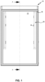
Figure 1 , the frontal view of a cooling device door comprising a rib is given. - In
Figure 2 , the lateral cross sectional view along the A-A axis illustrated inFigure 1 is given. - In
Figure 3 , the zoomed view of detail B illustrated inFigure 2 is given. - In
Figure 4 , the lateral view of the thermoform mould used in the production of an inner liner carrying a representative embodiment of the subject matter rib is given. - In
Figure 1 , a door (10) of a cooling device (not illustrated in the figure) is illustrated. The door (10) comprises an inner liner (20) which is made of a plastic based material and an outer frame (50) where the inner liner (20) is connected along the edges thereof. The inner liner (20) comprises a panel (22) and a support part (30) which is provided thereon in the form of an orthogonal projection. The support part (30) extends in a parallel and adjacent manner to both of the mutual orthogonal edges of the inner liner (20). A carrier part (40) is formed in a projection form on the support part's (30) inner wall (32) facing the panel (22) inner side and facing each other. The carrier part (40) provides assembly of shelf or similar keeping members to the door (10) or the assembly of the auxiliary members (not illustrated in the figure) like guide. - In
Figure 2 , the cross section of the door (10) along the A-A axis is illustrated. A door arm (60) of the door (10) is fixed on an outer frame (50). The support part (30), which exists on the right hand side inFigure 1 , is illustrated inFigure 2 . The support part (30) has an ear-like form. The support part (30) extends in an orthogonal manner to this, so as to join the panel (22) of the inner liner (20). The carrier part (40) is placed one above the other so as to have distance in between on the inner wall (32). - In
Figure 3 , the zoomed view of the carrier part (40) is given. The inner wall (32) of the support part (30) formed by the inner liner (20) is embossed outwardly and thereby a tab (42) is formed. The tab (42) has a planar front edge (41) and a rear edge (44) which is in the opposite direction. The front and the rear edge (41, 44) have a distance in between. The rear edge (44) has an undulated contour. Between the tab (42) and the inner liner (20) panel (22), pluralities of ribs (46) are formed in the support part (30). The form of the ribs (46) is configured in a manner extending in the transverse direction (y) of the support part (30). The ribs (46), which are in bar form, extend in an orthogonal manner to the rear edge (44) in a region limited by the rear edge (44) distance, so as to have a distance in between. There is a distance between the ribs (46) and the rear edge (44). - In
Figure 4 , a representative embodiment of a thermoform mould (70) where the production of the inner liner (20) is provided is illustrated. The thermoform mould (70) comprises a body (71), and a projection (72) formed outwardly on the upper part of the body (71). Pluralities of projections (74) are formed on the lateral surface of the projection (72). The projections (74) extend in the transverse direction (y) with respect to the body (71). There is a movable core (90) at the thermoform mould (70) body (71). Moreover, in the thermoform mould (70), there is a discharge hole (73) for providing vacuum during the thermoform process. - A plastic panel (not illustrated in the figure) is heated and smoothed and it is inflated by means of air flow. Afterwards, it is seated onto the thermoform mould (70) and the air is discharged. Meanwhile, the movable core (90) advances outwardly from the projection (72) and it forms the tab (42). At the same time, the projections (74) form the rib (46). The inner liner (20), which is formed by pulling back the movable core (90), is removed from the thermoform mould (70) in the transverse direction (y). Since the projection (74) extends in the transverse direction (y), the inner liner (20) which is made of plastic material can be easily removed from the mould by a slight bending.
- The rib (46) height is less than the tab (42) height. In this manner, the rib (46) may be formed by semi-circler embossments whose height is smaller than the half of the tab (42) height or the rib (46) may be formed by embossments in other forms whose edges are rounded so as not to give damage to the inner liner (20) during the removal of the inner liner (20) in the transverse direction. The ribs (46) can be placed to the support part (30) so as to comprise offset with respect to each other or so as to be at different lengths or so as to have equal lengths.
REFERENCE NUMBERS 10 Door 47 Edge 20 Inner liner 50 Outer frame 22 Panel 60 Door handle 30 Support part 70 Thermoform mould 32 Inner wall 71 Body 40 Carrier part 72 Projection 41 Front edge 73 Discharge hole 42 Tab 74 Projection 44 Rear edge 80 Insulation layer 46 Rib 90 Movable core y Transverse direction
Claims (1)
- A cooling device production method for producing a cooling device comprising an insulation layer (80) which expands and places between a plastic based inner liner (20) and an outer frame (50) so as to apply pressure; at least two mutual support parts (30) of the inner liner (20) which are formed so as to extend outwardly in transverse direction (y) and which are in shell form; a door (10) which is formed by the forming of an inner wall (32) of the support parts (30) facing each other and wherein the inner wall (32) comprises at least one tab (42), comprising pluralities of spaced ribs (46) which are formed by giving a predetermined form to the inner wall (32) and which are provided in the vicinity of the tab (42) in the support parts (30), wherein the tab (42) has a planar front edge (41) and a rear edge (44) which is in the opposite direction, wherein the front edge (41) and the rear edge (44) have a distance in between, wherein the rear edge (44) has an undulated contour, wherein the rib (46) comprises an embossment form extending in the transverse direction (y), wherein the ribs (46) extend between the tab's (42) rear edge (44) facing the inner liner (20), and the panel (22) of the inner liner (20) parallel to the outer frame (50), wherein the rear edge (44) contour follows the ribs' (46) line facing the rear edge (44), comprising the steps of heating a plastic based panel (22) on a thermoform mould (70) in opposite form of the inner liner (20) and covering said plastic based panel (22) onto the thermoform mould (70); forming the rib (46) together with the inner liner (20) by means of a projection (74) provided on the thermoform mould (70); forming the tab (42) and exiting the tab (42) by a movable core (90), which applies pressure to the support part (30); pulling and removing the inner liner (20) in the transverse direction (y) which is essentially orthogonal to the thermoform mould (70).
Priority Applications (1)
| Application Number | Priority Date | Filing Date | Title |
|---|---|---|---|
| PL11194455.9T PL2469204T5 (en) | 2010-12-24 | 2011-12-20 | A cooling device with a reinforced inner liner and production method for it |
Applications Claiming Priority (1)
| Application Number | Priority Date | Filing Date | Title |
|---|---|---|---|
| TR2010/10842A TR201010842A2 (en) | 2010-12-24 | 2010-12-24 | A cooler with reinforced inner liner and its production method |
Publications (4)
| Publication Number | Publication Date |
|---|---|
| EP2469204A2 EP2469204A2 (en) | 2012-06-27 |
| EP2469204A3 EP2469204A3 (en) | 2014-01-15 |
| EP2469204B1 EP2469204B1 (en) | 2018-08-29 |
| EP2469204B2 true EP2469204B2 (en) | 2025-06-04 |
Family
ID=45442922
Family Applications (1)
| Application Number | Title | Priority Date | Filing Date |
|---|---|---|---|
| EP11194455.9A Active EP2469204B2 (en) | 2010-12-24 | 2011-12-20 | A cooling device with a reinforced inner liner and production method for it |
Country Status (3)
| Country | Link |
|---|---|
| EP (1) | EP2469204B2 (en) |
| PL (1) | PL2469204T5 (en) |
| TR (1) | TR201010842A2 (en) |
Citations (4)
| Publication number | Priority date | Publication date | Assignee | Title |
|---|---|---|---|---|
| FR68736E (en) † | 1955-11-25 | 1958-06-09 | Thomson Houston Comp Francaise | Improvements to door shelves in refrigerator cabinets |
| KR970044864U (en) † | 1995-12-15 | 1997-07-31 | 대우자동차주식회사 | Vehicle's radiator cap |
| KR20010060723A (en) † | 1999-12-28 | 2001-07-07 | 구자홍 | Door liner for refrigerator |
| KR20100022742A (en) † | 2008-08-20 | 2010-03-03 | 엘지전자 주식회사 | A refrigerator |
Family Cites Families (5)
| Publication number | Priority date | Publication date | Assignee | Title |
|---|---|---|---|---|
| CA2155056C (en) | 1994-08-08 | 2007-03-06 | John R. Revlett | Refrigeration appliance door with reinforcement sheet |
| TW389825B (en) * | 1997-09-09 | 2000-05-11 | Fisher & Paykel | A refrigerator cabinet |
| US6574984B1 (en) * | 2002-02-07 | 2003-06-10 | Camco Inc. | Refrigerator door mounted water dispensing assembly |
| KR100633027B1 (en) | 2005-07-04 | 2006-10-11 | 삼성광주전자 주식회사 | Molds for shaping the inside of refrigerators and insides of refrigerators |
| KR101584808B1 (en) * | 2009-06-24 | 2016-01-22 | 엘지전자 주식회사 | A refrigerator with height adjustment storage |
-
2010
- 2010-12-24 TR TR2010/10842A patent/TR201010842A2/en unknown
-
2011
- 2011-12-20 EP EP11194455.9A patent/EP2469204B2/en active Active
- 2011-12-20 PL PL11194455.9T patent/PL2469204T5/en unknown
Patent Citations (4)
| Publication number | Priority date | Publication date | Assignee | Title |
|---|---|---|---|---|
| FR68736E (en) † | 1955-11-25 | 1958-06-09 | Thomson Houston Comp Francaise | Improvements to door shelves in refrigerator cabinets |
| KR970044864U (en) † | 1995-12-15 | 1997-07-31 | 대우자동차주식회사 | Vehicle's radiator cap |
| KR20010060723A (en) † | 1999-12-28 | 2001-07-07 | 구자홍 | Door liner for refrigerator |
| KR20100022742A (en) † | 2008-08-20 | 2010-03-03 | 엘지전자 주식회사 | A refrigerator |
Also Published As
| Publication number | Publication date |
|---|---|
| EP2469204A2 (en) | 2012-06-27 |
| PL2469204T5 (en) | 2025-08-04 |
| TR201010842A2 (en) | 2012-07-23 |
| PL2469204T3 (en) | 2019-01-31 |
| EP2469204A3 (en) | 2014-01-15 |
| EP2469204B1 (en) | 2018-08-29 |
Similar Documents
| Publication | Publication Date | Title |
|---|---|---|
| EP1741543B1 (en) | Interior finishing panel for vehicle and method of manufacturing the same | |
| JPS63172621A (en) | Synthetic molded form and manufacture thereof | |
| US6685875B2 (en) | Foamed thermoplastic resin molding and process for producing the same | |
| CN101119833A (en) | Vehicle component and method of manufacturing vehicle component | |
| CN103732940B (en) | Impact absorber and method for producing impact absorber | |
| IT7354185A1 (en) | REFRIGERATED CABINET STRUCTURE AND MANUFACTURE | |
| EP3774260B1 (en) | Foam and method of forming foam | |
| JP5595866B2 (en) | Interior product for vehicle and method for manufacturing interior product for vehicle | |
| EP2469204B2 (en) | A cooling device with a reinforced inner liner and production method for it | |
| JP5119315B2 (en) | Manufacturing method of resin panel | |
| JP4136985B2 (en) | Bonded blow molded article and method for producing the same. | |
| US7438845B2 (en) | Method for manufacturing article with integrally formed hooks with shear at hook-bearing surface | |
| JP5633922B2 (en) | Multilayer foam substrate and method for producing the same | |
| US20050161851A1 (en) | Touch fastener products | |
| JP5495437B2 (en) | Multilayer foam substrate and method for producing the same | |
| JP6496081B2 (en) | Molding method of resin foam with skin | |
| WO2012072476A2 (en) | A cooling device with reinforced liner | |
| US9783131B2 (en) | Decorated molded article | |
| JP4657489B2 (en) | Mold used for manufacturing plastic molding with grain pattern | |
| JP4725316B2 (en) | Molded product manufacturing method and molded product | |
| JP2012228823A (en) | Method of manufacturing interior automotive trim | |
| EP1491095A1 (en) | Cup-like cake container | |
| JP5665327B2 (en) | Manufacturing method of integrally molded product of resin foam and plate member, and integrally molded product thereof | |
| EP1922208A1 (en) | Method for producing an alveolar panel element particularly for coverings, packagings, supporting surfaces, and alveolar panel element produced thereby | |
| JP2008006729A (en) | Mold and method for molding skin material |
Legal Events
| Date | Code | Title | Description |
|---|---|---|---|
| AK | Designated contracting states |
Kind code of ref document: A2 Designated state(s): AL AT BE BG CH CY CZ DE DK EE ES FI FR GB GR HR HU IE IS IT LI LT LU LV MC MK MT NL NO PL PT RO RS SE SI SK SM TR |
|
| AX | Request for extension of the european patent |
Extension state: BA ME |
|
| PUAI | Public reference made under article 153(3) epc to a published international application that has entered the european phase |
Free format text: ORIGINAL CODE: 0009012 |
|
| PUAL | Search report despatched |
Free format text: ORIGINAL CODE: 0009013 |
|
| AK | Designated contracting states |
Kind code of ref document: A3 Designated state(s): AL AT BE BG CH CY CZ DE DK EE ES FI FR GB GR HR HU IE IS IT LI LT LU LV MC MK MT NL NO PL PT RO RS SE SI SK SM TR |
|
| AX | Request for extension of the european patent |
Extension state: BA ME |
|
| RIC1 | Information provided on ipc code assigned before grant |
Ipc: B29C 51/10 20060101ALI20131212BHEP Ipc: B29C 51/06 20060101ALI20131212BHEP Ipc: B29C 49/54 20060101ALI20131212BHEP Ipc: F25D 23/06 20060101AFI20131212BHEP |
|
| 17P | Request for examination filed |
Effective date: 20140715 |
|
| RBV | Designated contracting states (corrected) |
Designated state(s): AL AT BE BG CH CY CZ DE DK EE ES FI FR GB GR HR HU IE IS IT LI LT LU LV MC MK MT NL NO PL PT RO RS SE SI SK SM TR |
|
| RAP1 | Party data changed (applicant data changed or rights of an application transferred) |
Owner name: BSH HAUSGERAETE GMBH |
|
| STAA | Information on the status of an ep patent application or granted ep patent |
Free format text: STATUS: EXAMINATION IS IN PROGRESS |
|
| 17Q | First examination report despatched |
Effective date: 20170214 |
|
| GRAP | Despatch of communication of intention to grant a patent |
Free format text: ORIGINAL CODE: EPIDOSNIGR1 |
|
| STAA | Information on the status of an ep patent application or granted ep patent |
Free format text: STATUS: GRANT OF PATENT IS INTENDED |
|
| INTG | Intention to grant announced |
Effective date: 20180418 |
|
| GRAS | Grant fee paid |
Free format text: ORIGINAL CODE: EPIDOSNIGR3 |
|
| GRAA | (expected) grant |
Free format text: ORIGINAL CODE: 0009210 |
|
| STAA | Information on the status of an ep patent application or granted ep patent |
Free format text: STATUS: THE PATENT HAS BEEN GRANTED |
|
| AK | Designated contracting states |
Kind code of ref document: B1 Designated state(s): AL AT BE BG CH CY CZ DE DK EE ES FI FR GB GR HR HU IE IS IT LI LT LU LV MC MK MT NL NO PL PT RO RS SE SI SK SM TR |
|
| REG | Reference to a national code |
Ref country code: GB Ref legal event code: FG4D |
|
| REG | Reference to a national code |
Ref country code: CH Ref legal event code: EP |
|
| REG | Reference to a national code |
Ref country code: AT Ref legal event code: REF Ref document number: 1035597 Country of ref document: AT Kind code of ref document: T Effective date: 20180915 |
|
| REG | Reference to a national code |
Ref country code: IE Ref legal event code: FG4D |
|
| REG | Reference to a national code |
Ref country code: DE Ref legal event code: R096 Ref document number: 602011051481 Country of ref document: DE |
|
| REG | Reference to a national code |
Ref country code: NL Ref legal event code: MP Effective date: 20180829 |
|
| REG | Reference to a national code |
Ref country code: LT Ref legal event code: MG4D |
|
| PG25 | Lapsed in a contracting state [announced via postgrant information from national office to epo] |
Ref country code: BG Free format text: LAPSE BECAUSE OF FAILURE TO SUBMIT A TRANSLATION OF THE DESCRIPTION OR TO PAY THE FEE WITHIN THE PRESCRIBED TIME-LIMIT Effective date: 20181129 Ref country code: NL Free format text: LAPSE BECAUSE OF FAILURE TO SUBMIT A TRANSLATION OF THE DESCRIPTION OR TO PAY THE FEE WITHIN THE PRESCRIBED TIME-LIMIT Effective date: 20180829 Ref country code: GR Free format text: LAPSE BECAUSE OF FAILURE TO SUBMIT A TRANSLATION OF THE DESCRIPTION OR TO PAY THE FEE WITHIN THE PRESCRIBED TIME-LIMIT Effective date: 20181130 Ref country code: LT Free format text: LAPSE BECAUSE OF FAILURE TO SUBMIT A TRANSLATION OF THE DESCRIPTION OR TO PAY THE FEE WITHIN THE PRESCRIBED TIME-LIMIT Effective date: 20180829 Ref country code: IS Free format text: LAPSE BECAUSE OF FAILURE TO SUBMIT A TRANSLATION OF THE DESCRIPTION OR TO PAY THE FEE WITHIN THE PRESCRIBED TIME-LIMIT Effective date: 20181229 Ref country code: RS Free format text: LAPSE BECAUSE OF FAILURE TO SUBMIT A TRANSLATION OF THE DESCRIPTION OR TO PAY THE FEE WITHIN THE PRESCRIBED TIME-LIMIT Effective date: 20180829 Ref country code: SE Free format text: LAPSE BECAUSE OF FAILURE TO SUBMIT A TRANSLATION OF THE DESCRIPTION OR TO PAY THE FEE WITHIN THE PRESCRIBED TIME-LIMIT Effective date: 20180829 Ref country code: FI Free format text: LAPSE BECAUSE OF FAILURE TO SUBMIT A TRANSLATION OF THE DESCRIPTION OR TO PAY THE FEE WITHIN THE PRESCRIBED TIME-LIMIT Effective date: 20180829 Ref country code: NO Free format text: LAPSE BECAUSE OF FAILURE TO SUBMIT A TRANSLATION OF THE DESCRIPTION OR TO PAY THE FEE WITHIN THE PRESCRIBED TIME-LIMIT Effective date: 20181129 |
|
| REG | Reference to a national code |
Ref country code: AT Ref legal event code: MK05 Ref document number: 1035597 Country of ref document: AT Kind code of ref document: T Effective date: 20180829 |
|
| PG25 | Lapsed in a contracting state [announced via postgrant information from national office to epo] |
Ref country code: HR Free format text: LAPSE BECAUSE OF FAILURE TO SUBMIT A TRANSLATION OF THE DESCRIPTION OR TO PAY THE FEE WITHIN THE PRESCRIBED TIME-LIMIT Effective date: 20180829 Ref country code: AL Free format text: LAPSE BECAUSE OF FAILURE TO SUBMIT A TRANSLATION OF THE DESCRIPTION OR TO PAY THE FEE WITHIN THE PRESCRIBED TIME-LIMIT Effective date: 20180829 Ref country code: LV Free format text: LAPSE BECAUSE OF FAILURE TO SUBMIT A TRANSLATION OF THE DESCRIPTION OR TO PAY THE FEE WITHIN THE PRESCRIBED TIME-LIMIT Effective date: 20180829 |
|
| PG25 | Lapsed in a contracting state [announced via postgrant information from national office to epo] |
Ref country code: AT Free format text: LAPSE BECAUSE OF FAILURE TO SUBMIT A TRANSLATION OF THE DESCRIPTION OR TO PAY THE FEE WITHIN THE PRESCRIBED TIME-LIMIT Effective date: 20180829 Ref country code: EE Free format text: LAPSE BECAUSE OF FAILURE TO SUBMIT A TRANSLATION OF THE DESCRIPTION OR TO PAY THE FEE WITHIN THE PRESCRIBED TIME-LIMIT Effective date: 20180829 Ref country code: RO Free format text: LAPSE BECAUSE OF FAILURE TO SUBMIT A TRANSLATION OF THE DESCRIPTION OR TO PAY THE FEE WITHIN THE PRESCRIBED TIME-LIMIT Effective date: 20180829 Ref country code: CZ Free format text: LAPSE BECAUSE OF FAILURE TO SUBMIT A TRANSLATION OF THE DESCRIPTION OR TO PAY THE FEE WITHIN THE PRESCRIBED TIME-LIMIT Effective date: 20180829 Ref country code: ES Free format text: LAPSE BECAUSE OF FAILURE TO SUBMIT A TRANSLATION OF THE DESCRIPTION OR TO PAY THE FEE WITHIN THE PRESCRIBED TIME-LIMIT Effective date: 20180829 |
|
| REG | Reference to a national code |
Ref country code: DE Ref legal event code: R026 Ref document number: 602011051481 Country of ref document: DE |
|
| PG25 | Lapsed in a contracting state [announced via postgrant information from national office to epo] |
Ref country code: SM Free format text: LAPSE BECAUSE OF FAILURE TO SUBMIT A TRANSLATION OF THE DESCRIPTION OR TO PAY THE FEE WITHIN THE PRESCRIBED TIME-LIMIT Effective date: 20180829 Ref country code: SK Free format text: LAPSE BECAUSE OF FAILURE TO SUBMIT A TRANSLATION OF THE DESCRIPTION OR TO PAY THE FEE WITHIN THE PRESCRIBED TIME-LIMIT Effective date: 20180829 Ref country code: DK Free format text: LAPSE BECAUSE OF FAILURE TO SUBMIT A TRANSLATION OF THE DESCRIPTION OR TO PAY THE FEE WITHIN THE PRESCRIBED TIME-LIMIT Effective date: 20180829 |
|
| PLBI | Opposition filed |
Free format text: ORIGINAL CODE: 0009260 |
|
| PLAX | Notice of opposition and request to file observation + time limit sent |
Free format text: ORIGINAL CODE: EPIDOSNOBS2 |
|
| 26 | Opposition filed |
Opponent name: LOUIS POEHLAU LOHRENTZ Effective date: 20190529 |
|
| REG | Reference to a national code |
Ref country code: CH Ref legal event code: PL |
|
| GBPC | Gb: european patent ceased through non-payment of renewal fee |
Effective date: 20181220 |
|
| PG25 | Lapsed in a contracting state [announced via postgrant information from national office to epo] |
Ref country code: SI Free format text: LAPSE BECAUSE OF FAILURE TO SUBMIT A TRANSLATION OF THE DESCRIPTION OR TO PAY THE FEE WITHIN THE PRESCRIBED TIME-LIMIT Effective date: 20180829 Ref country code: LU Free format text: LAPSE BECAUSE OF NON-PAYMENT OF DUE FEES Effective date: 20181220 Ref country code: MC Free format text: LAPSE BECAUSE OF FAILURE TO SUBMIT A TRANSLATION OF THE DESCRIPTION OR TO PAY THE FEE WITHIN THE PRESCRIBED TIME-LIMIT Effective date: 20180829 |
|
| PLBB | Reply of patent proprietor to notice(s) of opposition received |
Free format text: ORIGINAL CODE: EPIDOSNOBS3 |
|
| REG | Reference to a national code |
Ref country code: IE Ref legal event code: MM4A |
|
| REG | Reference to a national code |
Ref country code: BE Ref legal event code: MM Effective date: 20181231 |
|
| PG25 | Lapsed in a contracting state [announced via postgrant information from national office to epo] |
Ref country code: IE Free format text: LAPSE BECAUSE OF NON-PAYMENT OF DUE FEES Effective date: 20181220 Ref country code: FR Free format text: LAPSE BECAUSE OF NON-PAYMENT OF DUE FEES Effective date: 20181231 |
|
| PG25 | Lapsed in a contracting state [announced via postgrant information from national office to epo] |
Ref country code: BE Free format text: LAPSE BECAUSE OF NON-PAYMENT OF DUE FEES Effective date: 20181231 |
|
| PG25 | Lapsed in a contracting state [announced via postgrant information from national office to epo] |
Ref country code: GB Free format text: LAPSE BECAUSE OF NON-PAYMENT OF DUE FEES Effective date: 20181220 Ref country code: CH Free format text: LAPSE BECAUSE OF NON-PAYMENT OF DUE FEES Effective date: 20181231 Ref country code: LI Free format text: LAPSE BECAUSE OF NON-PAYMENT OF DUE FEES Effective date: 20181231 |
|
| PG25 | Lapsed in a contracting state [announced via postgrant information from national office to epo] |
Ref country code: MT Free format text: LAPSE BECAUSE OF NON-PAYMENT OF DUE FEES Effective date: 20181220 |
|
| PG25 | Lapsed in a contracting state [announced via postgrant information from national office to epo] |
Ref country code: PT Free format text: LAPSE BECAUSE OF FAILURE TO SUBMIT A TRANSLATION OF THE DESCRIPTION OR TO PAY THE FEE WITHIN THE PRESCRIBED TIME-LIMIT Effective date: 20180829 |
|
| PG25 | Lapsed in a contracting state [announced via postgrant information from national office to epo] |
Ref country code: HU Free format text: LAPSE BECAUSE OF FAILURE TO SUBMIT A TRANSLATION OF THE DESCRIPTION OR TO PAY THE FEE WITHIN THE PRESCRIBED TIME-LIMIT; INVALID AB INITIO Effective date: 20111220 Ref country code: MK Free format text: LAPSE BECAUSE OF NON-PAYMENT OF DUE FEES Effective date: 20180829 Ref country code: CY Free format text: LAPSE BECAUSE OF FAILURE TO SUBMIT A TRANSLATION OF THE DESCRIPTION OR TO PAY THE FEE WITHIN THE PRESCRIBED TIME-LIMIT Effective date: 20180829 |
|
| APBM | Appeal reference recorded |
Free format text: ORIGINAL CODE: EPIDOSNREFNO |
|
| APBP | Date of receipt of notice of appeal recorded |
Free format text: ORIGINAL CODE: EPIDOSNNOA2O |
|
| APAH | Appeal reference modified |
Free format text: ORIGINAL CODE: EPIDOSCREFNO |
|
| APBM | Appeal reference recorded |
Free format text: ORIGINAL CODE: EPIDOSNREFNO |
|
| APBP | Date of receipt of notice of appeal recorded |
Free format text: ORIGINAL CODE: EPIDOSNNOA2O |
|
| APBQ | Date of receipt of statement of grounds of appeal recorded |
Free format text: ORIGINAL CODE: EPIDOSNNOA3O |
|
| APAL | Date of receipt of statement of grounds of an appeal modified |
Free format text: ORIGINAL CODE: EPIDOSCNOA3O |
|
| APBQ | Date of receipt of statement of grounds of appeal recorded |
Free format text: ORIGINAL CODE: EPIDOSNNOA3O |
|
| REG | Reference to a national code |
Ref country code: DE Ref legal event code: R084 Ref document number: 602011051481 Country of ref document: DE |
|
| P01 | Opt-out of the competence of the unified patent court (upc) registered |
Effective date: 20230504 |
|
| PLAB | Opposition data, opponent's data or that of the opponent's representative modified |
Free format text: ORIGINAL CODE: 0009299OPPO |
|
| R26 | Opposition filed (corrected) |
Opponent name: LOUIS POEHLAU LOHRENTZ PATENTANWAELTE PARTNERSCHAFT MBB Effective date: 20190529 |
|
| APBU | Appeal procedure closed |
Free format text: ORIGINAL CODE: EPIDOSNNOA9O |
|
| PGFP | Annual fee paid to national office [announced via postgrant information from national office to epo] |
Ref country code: IT Payment date: 20231229 Year of fee payment: 13 |
|
| PGFP | Annual fee paid to national office [announced via postgrant information from national office to epo] |
Ref country code: PL Payment date: 20241211 Year of fee payment: 14 |
|
| PUAH | Patent maintained in amended form |
Free format text: ORIGINAL CODE: 0009272 |
|
| STAA | Information on the status of an ep patent application or granted ep patent |
Free format text: STATUS: PATENT MAINTAINED AS AMENDED |
|
| 27A | Patent maintained in amended form |
Effective date: 20250604 |
|
| AK | Designated contracting states |
Kind code of ref document: B2 Designated state(s): AL AT BE BG CH CY CZ DE DK EE ES FI FR GB GR HR HU IE IS IT LI LT LU LV MC MK MT NL NO PL PT RO RS SE SI SK SM TR |
|
| REG | Reference to a national code |
Ref country code: DE Ref legal event code: R102 Ref document number: 602011051481 Country of ref document: DE |
|
| PG25 | Lapsed in a contracting state [announced via postgrant information from national office to epo] |
Ref country code: IT Free format text: LAPSE BECAUSE OF NON-PAYMENT OF DUE FEES Effective date: 20241220 |
|
| PGFP | Annual fee paid to national office [announced via postgrant information from national office to epo] |
Ref country code: TR Payment date: 20251216 Year of fee payment: 15 |
|
| PGFP | Annual fee paid to national office [announced via postgrant information from national office to epo] |
Ref country code: DE Payment date: 20251231 Year of fee payment: 15 |