EP2469104A2 - Component maintenance action identification - Google Patents
Component maintenance action identification Download PDFInfo
- Publication number
- EP2469104A2 EP2469104A2 EP11191949A EP11191949A EP2469104A2 EP 2469104 A2 EP2469104 A2 EP 2469104A2 EP 11191949 A EP11191949 A EP 11191949A EP 11191949 A EP11191949 A EP 11191949A EP 2469104 A2 EP2469104 A2 EP 2469104A2
- Authority
- EP
- European Patent Office
- Prior art keywords
- component
- current
- maintenance action
- initiating
- controller
- Prior art date
- Legal status (The legal status is an assumption and is not a legal conclusion. Google has not performed a legal analysis and makes no representation as to the accuracy of the status listed.)
- Granted
Links
- 238000012423 maintenance Methods 0.000 title claims abstract description 30
- 238000000034 method Methods 0.000 claims abstract description 14
- 230000000977 initiatory effect Effects 0.000 claims abstract description 13
- 238000012544 monitoring process Methods 0.000 claims abstract description 6
- 230000009977 dual effect Effects 0.000 description 2
- 230000000694 effects Effects 0.000 description 2
- 239000012530 fluid Substances 0.000 description 2
- 230000006870 function Effects 0.000 description 2
- 238000007689 inspection Methods 0.000 description 2
- 238000013459 approach Methods 0.000 description 1
- 230000000712 assembly Effects 0.000 description 1
- 238000000429 assembly Methods 0.000 description 1
- 239000000872 buffer Substances 0.000 description 1
- 230000015556 catabolic process Effects 0.000 description 1
- 238000006731 degradation reaction Methods 0.000 description 1
- 238000012986 modification Methods 0.000 description 1
- 230000004048 modification Effects 0.000 description 1
- 230000003287 optical effect Effects 0.000 description 1
- 238000012545 processing Methods 0.000 description 1
- 230000004044 response Effects 0.000 description 1
- 239000004065 semiconductor Substances 0.000 description 1
- 230000000007 visual effect Effects 0.000 description 1
Images

Classifications
-
- F—MECHANICAL ENGINEERING; LIGHTING; HEATING; WEAPONS; BLASTING
- F15—FLUID-PRESSURE ACTUATORS; HYDRAULICS OR PNEUMATICS IN GENERAL
- F15B—SYSTEMS ACTING BY MEANS OF FLUIDS IN GENERAL; FLUID-PRESSURE ACTUATORS, e.g. SERVOMOTORS; DETAILS OF FLUID-PRESSURE SYSTEMS, NOT OTHERWISE PROVIDED FOR
- F15B19/00—Testing; Calibrating; Fault detection or monitoring; Simulation or modelling of fluid-pressure systems or apparatus not otherwise provided for
- F15B19/005—Fault detection or monitoring
Definitions
- This disclosure relates generally to maintaining a component and, more particularly, to monitoring an electrical input current of a device to effectively time a maintenance action on the component.
- Complex assemblies such as turbomachines, include various individual components. Some of the individual components include portions that move in response to an applied electrical input current. Such movement is needed to move variable geometry blades within a turbomachine, for example.
- An example component may include an electromechanical servovalve (EHSV) and an actuator.
- the null bias electrical current of the EHSV is the electrical current input that is needed to overcome the actuator null effect, or cause the actuator to maintain a steady state position. If the input current is larger than the null bias current, then the current will open the EHSV and port more fluid to the actuator, which drives the actuator to a desired extended position. If the input current is smaller than the null bias current, then current will open the EHSV and port more fluid to the actuator which drives the actuator to a desired retracted position.
- Components are designed so that the current required to overcome the null bias and move the component to a desired position falls within a normal range of industry standards.
- a range of electrical input current is specified, rather than an exact value, because of build tolerances and other variables.
- the EHSV is typically biased to return to the home (or null) position when the current is not applied. Biasing the EHSV to the home position ensures that the EHSV is in a known position when no current is applied.
- extending and retracting the actuator of the component moves the variable geometry blade within a turbomachine.
- An example method of initiating a maintenance action on a component includes monitoring an electrical current required to maintain a steady state position. The method then initiates a maintenance action on the component based on the monitored current.
- An example component arrangement includes a component configured to move between a home position and an activated position.
- a controller is configured to monitor an input current, for example the null bias current required to control to the component. The controller initiates a maintenance action based on the current.
- An example turbomachine control assembly includes a component configured to move from a home position to an activated position when a current is applied to the component. At least one sensor is configured to monitor the actual input electrical current required to control the component. A controller initiates a maintenance action based on the null bias current required to control the component.
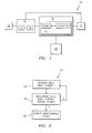
- an example component control arrangement 10 includes a controller 14, a component 18, and a current supply 22.
- the component 18 is a movable component activated by a current.
- the controller 14 controller supplies current to the component 18 from the current supply 22.
- the controller 14 is configured to initiate movement of the component 18 from the home position to an activated position by commanding the current supply 22 to supply the component 18 with a 10 milliamp current, for example.
- the component 18 defaults to the home position when not supplied with a current.
- the controller 14 is further configured to monitor the position of the component 18. The controller 14 can thus determine whether the commanded current resulted in the component 18 moving to the desired position.
- a sensor (not shown) is used to monitor the position of the component 18. A person having skill in this art would understand how to monitor the position of the component 18 using a sensor.
- the component 18 includes an extendable portion 24.
- the home position corresponds to the portion 24 in a fully retracted position
- the activated position corresponds to the portion 24 at a partially extended position, such as a mid-travel position.
- the extension and retraction of the portion 24 moves a moveable component 28, such as a variable geometry blade within a turbomachine.
- the example controller 14 includes a memory portion 32 and a processor 36.
- the memory portion 32 stores a program that is executed by the processor 36.
- the program enables the controller 14 to initiate and monitor the electrical input current provided to the component 18, and to monitor the position of the portion 24, the moveable, or both.
- the example controller 14 is also linked to a display 38, such as a computer monitor.
- controller 14 may include portions of a dual architecture micro server card.
- the memory portion 32 and the processor 36 also may include portions of a dual architecture micro server card.
- the controller 14 can additionally include one or more input and/or output (I/O) device interface(s) that are communicatively coupled via a local interface.
- the local interface can include, for example but not limited to, one or more buses and/or other wired or wireless connections.
- the local interface may have additional elements, which are omitted for simplicity, such as additional controllers, buffers (caches), drivers, repeaters, and receivers to enable communications.
- the local interface may include address, control, and/or data connections to enable appropriate communications among the aforementioned components.
- the example processor 36 used within the controller 14 executes software code, particularly software code stored in the memory portion 32.
- the processor 36 can be a custom made or commercially available processor, a central processing unit (CPU), an auxiliary processor among several processors associated with the computing device, a semiconductor based microprocessor (in the form of a microchip or chip set) or generally any device for executing software instructions.
- the memory portion 32 can include any one or combination of volatile memory elements (e.g., random access memory (RAM, such as DRAM, SRAM, SDRAM, VRAM, etc.)) and/or nonvolatile memory elements (e.g., ROM, hard drive, tape, CD-ROM, etc.).
- volatile memory elements e.g., random access memory (RAM, such as DRAM, SRAM, SDRAM, VRAM, etc.)
- nonvolatile memory elements e.g., ROM, hard drive, tape, CD-ROM, etc.
- the memory may incorporate electronic, magnetic, optical, and/or other types of storage media. Note that the memory can also have a distributed architecture, where various components are situated remotely from one another, but can be accessed by the processor.
- the software in the memory portion 32 may include one or more additional or separate programs, each of which includes an ordered listing of executable instructions for implementing logical functions.
- a system component embodied as software may also be construed as a source program, executable program (object code), script, or any other entity comprising a set of instructions to be performed.
- the program is translated via a compiler, assembler, interpreter, or the like, which may or may not be included within the memory.
- the Input/Output devices that may be coupled to system I/O Interface(s) may include input devices, for example but not limited to, a keyboard, mouse, scanner, microphone, camera, proximity device, etc. Further, the Input/Output devices may also include output devices, for example but not limited to, a printer, display, etc. Finally, the Input/Output devices may further include devices that communicate both as inputs and outputs, for instance but not limited to, a modulator/demodulator (modem; for accessing another device, system, or network), a radio frequency (RF) or other transceiver, a telephonic interface, a bridge, a router, etc.
- modem for accessing another device, system, or network
- RF radio frequency
- an example program 50, or method, executed by the processor 36 includes a step 54.
- the step 54 monitors the current required to maintain a steady state position (null bias current) of the component 18. This current is typically referred to as the null bias current.
- the program 50 determines if the monitored null bias current is within a desired acceptable range at a step 58.
- the desired range of null bias current is stored in the memory portion 32 in this example. If the monitored null bias current is within the desired range of currents, the method returns to the step 54 and continues monitoring.
- program 50 initiates a maintenance action at a step 62.
- the step 62 may include initiating a visual cue on the display 38 linked to the controller 14.
- the display 38 may show the name of the component 18 and a description that the component 18 needs to be inspected, repaired, or replaced. Industry experience indicates that this condition is due to component wear and fatigue over it life.
- the maintenance actions are typically actions performed on the component when the component 18 is not operating in an acceptable manner. Various types of maintenance actions could be displayed. The maintenance actions may depend on the type of component 18.
- the example program 50 initiates the maintenance action at the step 62 based on the step 58. That is, initiating the maintenance action is based on a monitored null bias current that is not within the acceptable range.
- initiating the maintenance action is based on a monitored null bias current that is trending downward or upward beyond typical operating values. For example, if the monitored current increases over time from 10 milliamps, to 11 milliamps, to 12 milliamps, etc., a maintenance action is initiated. Such an approach may be useful to identify a component that is gradually failing.
- an example component assembly 70 includes an electromechanical servo valve (EHSV) 74 configured to initiate movement of a rod 78 between a home position 82a and an activated position 82b.
- EHSV electromechanical servo valve
- Moving the rod 78 moves a variable geometry blade (not shown) within a turbomachine, such as a gas turbine engine.
- the activated position 82b represents a desired position of the rod 78, such as a mid-travel position.
- the assembly 70 is designed so that the input electrical current required to hold the rod 78 a desired position will fall between 8 and 12 milliamps.
- the assembly 70 actually requires a 14 milliamps current to hold the rod 78 in the desired position.
- a degradation in the assembly 70 may be the cause of the increased null bias current.
- the program 50 ( Figure 2 ), would initiate a maintenance action, such as an inspection of the assembly 70. The inspection takes place before the assembly 70 experiences a mechanical failure.
- Features of the disclosed examples include identifying potential maintenance issues within movable components based on currents supplied to the components. A mechanical failure is thus not required before a maintenance activity is required.
Abstract
Description
- This disclosure relates generally to maintaining a component and, more particularly, to monitoring an electrical input current of a device to effectively time a maintenance action on the component.
- Complex assemblies, such as turbomachines, include various individual components. Some of the individual components include portions that move in response to an applied electrical input current. Such movement is needed to move variable geometry blades within a turbomachine, for example.
- An example component may include an electromechanical servovalve (EHSV) and an actuator. The null bias electrical current of the EHSV is the electrical current input that is needed to overcome the actuator null effect, or cause the actuator to maintain a steady state position. If the input current is larger than the null bias current, then the current will open the EHSV and port more fluid to the actuator, which drives the actuator to a desired extended position. If the input current is smaller than the null bias current, then current will open the EHSV and port more fluid to the actuator which drives the actuator to a desired retracted position. Components are designed so that the current required to overcome the null bias and move the component to a desired position falls within a normal range of industry standards. A range of electrical input current is specified, rather than an exact value, because of build tolerances and other variables. The EHSV is typically biased to return to the home (or null) position when the current is not applied. Biasing the EHSV to the home position ensures that the EHSV is in a known position when no current is applied.
- In this example, extending and retracting the actuator of the component moves the variable geometry blade within a turbomachine.
- An example method of initiating a maintenance action on a component includes monitoring an electrical current required to maintain a steady state position. The method then initiates a maintenance action on the component based on the monitored current.
- An example component arrangement includes a component configured to move between a home position and an activated position. A controller is configured to monitor an input current, for example the null bias current required to control to the component. The controller initiates a maintenance action based on the current.
- An example turbomachine control assembly includes a component configured to move from a home position to an activated position when a current is applied to the component. At least one sensor is configured to monitor the actual input electrical current required to control the component. A controller initiates a maintenance action based on the null bias current required to control the component.
- These and other features of the disclosed examples can be best understood from the following specification and drawings, the following of which is a brief description.
-
-
Figure 1 shows a schematic view of an example component monitoring arrangement. -
Figure 2 shows the flow of an example method used by a controller of theFigure 1 arrangement. -
Figure 3A shows a side view of an example component having a rod in a home position. -
Figure 3B shows a side view of theFigure 3A component having the rod in an activated position. - Referring to
Figure 1 , an examplecomponent control arrangement 10 includes acontroller 14, acomponent 18, and acurrent supply 22. Thecomponent 18 is a movable component activated by a current. Thecontroller 14 controller supplies current to thecomponent 18 from thecurrent supply 22. - The
controller 14 is configured to initiate movement of thecomponent 18 from the home position to an activated position by commanding thecurrent supply 22 to supply thecomponent 18 with a 10 milliamp current, for example. In this example, thecomponent 18 defaults to the home position when not supplied with a current. - The
controller 14 is further configured to monitor the position of thecomponent 18. Thecontroller 14 can thus determine whether the commanded current resulted in thecomponent 18 moving to the desired position. In one example, a sensor (not shown) is used to monitor the position of thecomponent 18. A person having skill in this art would understand how to monitor the position of thecomponent 18 using a sensor. - In this example, the
component 18 includes anextendable portion 24. The home position corresponds to theportion 24 in a fully retracted position, and the activated position corresponds to theportion 24 at a partially extended position, such as a mid-travel position. The extension and retraction of theportion 24 moves amoveable component 28, such as a variable geometry blade within a turbomachine. - The
example controller 14 includes amemory portion 32 and aprocessor 36. Thememory portion 32 stores a program that is executed by theprocessor 36. The program enables thecontroller 14 to initiate and monitor the electrical input current provided to thecomponent 18, and to monitor the position of theportion 24, the moveable, or both. Theexample controller 14 is also linked to adisplay 38, such as a computer monitor. - Many computing devices can be used to implement various functions described herein. For example, the
controller 14 may include portions of a dual architecture micro server card. Thememory portion 32 and theprocessor 36 also may include portions of a dual architecture micro server card. - In terms of hardware architecture, the
controller 14 can additionally include one or more input and/or output (I/O) device interface(s) that are communicatively coupled via a local interface. The local interface can include, for example but not limited to, one or more buses and/or other wired or wireless connections. The local interface may have additional elements, which are omitted for simplicity, such as additional controllers, buffers (caches), drivers, repeaters, and receivers to enable communications. Further, the local interface may include address, control, and/or data connections to enable appropriate communications among the aforementioned components. - The
example processor 36 used within thecontroller 14 executes software code, particularly software code stored in thememory portion 32. Theprocessor 36 can be a custom made or commercially available processor, a central processing unit (CPU), an auxiliary processor among several processors associated with the computing device, a semiconductor based microprocessor (in the form of a microchip or chip set) or generally any device for executing software instructions. - The
memory portion 32 can include any one or combination of volatile memory elements (e.g., random access memory (RAM, such as DRAM, SRAM, SDRAM, VRAM, etc.)) and/or nonvolatile memory elements (e.g., ROM, hard drive, tape, CD-ROM, etc.). Moreover, the memory may incorporate electronic, magnetic, optical, and/or other types of storage media. Note that the memory can also have a distributed architecture, where various components are situated remotely from one another, but can be accessed by the processor. - The software in the
memory portion 32 may include one or more additional or separate programs, each of which includes an ordered listing of executable instructions for implementing logical functions. A system component embodied as software may also be construed as a source program, executable program (object code), script, or any other entity comprising a set of instructions to be performed. When constructed as a source program, the program is translated via a compiler, assembler, interpreter, or the like, which may or may not be included within the memory. - The Input/Output devices that may be coupled to system I/O Interface(s) may include input devices, for example but not limited to, a keyboard, mouse, scanner, microphone, camera, proximity device, etc. Further, the Input/Output devices may also include output devices, for example but not limited to, a printer, display, etc. Finally, the Input/Output devices may further include devices that communicate both as inputs and outputs, for instance but not limited to, a modulator/demodulator (modem; for accessing another device, system, or network), a radio frequency (RF) or other transceiver, a telephonic interface, a bridge, a router, etc.
- Referring now to
Figure 2 with continuing reference toFigure 1 , anexample program 50, or method, executed by theprocessor 36 includes astep 54. Thestep 54 monitors the current required to maintain a steady state position (null bias current) of thecomponent 18. This current is typically referred to as the null bias current. - The
program 50 then determines if the monitored null bias current is within a desired acceptable range at astep 58. The desired range of null bias current is stored in thememory portion 32 in this example. If the monitored null bias current is within the desired range of currents, the method returns to thestep 54 and continues monitoring. - If the monitored null bias current is not within the desired range,
program 50 initiates a maintenance action at astep 62. Thestep 62 may include initiating a visual cue on thedisplay 38 linked to thecontroller 14. For example, thedisplay 38 may show the name of thecomponent 18 and a description that thecomponent 18 needs to be inspected, repaired, or replaced. Industry experience indicates that this condition is due to component wear and fatigue over it life. The maintenance actions are typically actions performed on the component when thecomponent 18 is not operating in an acceptable manner. Various types of maintenance actions could be displayed. The maintenance actions may depend on the type ofcomponent 18. - The
example program 50 initiates the maintenance action at thestep 62 based on thestep 58. That is, initiating the maintenance action is based on a monitored null bias current that is not within the acceptable range. - In another example, initiating the maintenance action is based on a monitored null bias current that is trending downward or upward beyond typical operating values. For example, if the monitored current increases over time from 10 milliamps, to 11 milliamps, to 12 milliamps, etc., a maintenance action is initiated. Such an approach may be useful to identify a component that is gradually failing.
- Referring to
Figures 3A and 3B , anexample component assembly 70 includes an electromechanical servo valve (EHSV) 74 configured to initiate movement of arod 78 between ahome position 82a and an activatedposition 82b. Moving therod 78 moves a variable geometry blade (not shown) within a turbomachine, such as a gas turbine engine. The activatedposition 82b represents a desired position of therod 78, such as a mid-travel position. - Supplying the
assembly 70 with sufficient current allows more flow through theEHSV 74, which causes therod 78 to extend to the desired position. The input current to hold therod 78 in the desired position is called the null bias current. Theassembly 70 is designed so that the input electrical current required to hold the rod 78 a desired position will fall between 8 and 12 milliamps. - In this example, however, the
assembly 70 actually requires a 14 milliamps current to hold therod 78 in the desired position. A degradation in theassembly 70 may be the cause of the increased null bias current. - As can be appreciated, the actual null bias current of 14 milliamps is outside the acceptable range of null bias currents. Thus, the program 50 (
Figure 2 ), would initiate a maintenance action, such as an inspection of theassembly 70. The inspection takes place before theassembly 70 experiences a mechanical failure. - Features of the disclosed examples include identifying potential maintenance issues within movable components based on currents supplied to the components. A mechanical failure is thus not required before a maintenance activity is required.
- The preceding description is exemplary rather than limiting in nature. Variations and modifications to the disclosed examples may become apparent to those skilled in the art that do not necessarily depart from the essence of this disclosure. Thus, the scope of legal protection given to this disclosure can only be determined by studying the following claims.
Claims (15)
- A method of initiating a maintenance action on a component (18), comprising:monitoring an electrical input current required to hold a component in a steady state position; andinitiating a maintenance action on the component (18) based on the monitored current.
- The method of claim 1, including initiating the maintenance action when the actual current is more than or less than an acceptable range of currents.
- The method of claim 2, wherein the desired range of current is 8 milliamps to 12 milliamps.
- The method of any preceding claim, including initiating the maintenance action when the actual current trends higher or trends lower.
- The method of any preceding claim, wherein the electrical input current is a null bias current.
- The method of any preceding claim, wherein the component (18) is an electromechanical servovalve.
- The method of any preceding claim, wherein the initiating is based on the monitored current that is outside an acceptable range for operation.
- A component arrangement, comprising:a component (18) configured to move between a home position and an activated position; anda controller (14) configured to monitor an electrical input current that is provided to the component (18), and to initiate an maintenance action based on the current.
- The component arrangement of claim 8, wherein the controller (14) is configured to initiate the maintenance action when the monitored current is more than or less than an acceptable range of currents.
- The component arrangement of claim 9, wherein the acceptable range of current is 8 milliamps to 12 milliamps.
- The component arrangement of claim 8, 9 or 10, including initiating the maintenance action when the current that is monitored trends higher or trends lower.
- The component arrangement of any of claims 8 to 11, wherein the current is a null bias current.
- A turbomachine control assembly, comprising:a component (18) configured to move from an home position to an activated position when a current is applied to the component;at least one sensor configured to monitor an actual electrical input current that holds the component in a steady-state position; anda controller (14) that initiates a maintenance action based on the actual electrical input current.
- The component arrangement of any of claims 8 to 12 or the turbomachine control assembly of claim 13, wherein the component is an electromechanical servovalve, for example a electromechanical servovalve configured to actuate a variable geometry blade; or is an aircraft gas turbine engine component, and the maintenance action is an action performed when the aircraft gas turbine engine component is not in flight.
- The turbomachine control assembly of claim 14, including initiating the maintenance action when the current required to hold the component (18) at a steady state position is outside the acceptable range for control of the component, or initiating the maintenance action when the actual input electrical current required to hold the component (18) at a steady state position trends higher or trends lower.
Applications Claiming Priority (1)
| Application Number | Priority Date | Filing Date | Title |
|---|---|---|---|
| US12/975,399 US9512861B2 (en) | 2010-12-22 | 2010-12-22 | Component maintenance action identification |
Publications (3)
| Publication Number | Publication Date |
|---|---|
| EP2469104A2 true EP2469104A2 (en) | 2012-06-27 |
| EP2469104A3 EP2469104A3 (en) | 2014-03-12 |
| EP2469104B1 EP2469104B1 (en) | 2018-02-07 |
Family
ID=45464231
Family Applications (1)
| Application Number | Title | Priority Date | Filing Date |
|---|---|---|---|
| EP11191949.4A Active EP2469104B1 (en) | 2010-12-22 | 2011-12-05 | Component maintenance action identification |
Country Status (2)
| Country | Link |
|---|---|
| US (1) | US9512861B2 (en) |
| EP (1) | EP2469104B1 (en) |
Families Citing this family (2)
| Publication number | Priority date | Publication date | Assignee | Title |
|---|---|---|---|---|
| US9909442B2 (en) | 2015-07-02 | 2018-03-06 | General Electric Company | Method of controlling a position actuation system component for a gas turbine engine |
| US10052768B1 (en) | 2015-12-28 | 2018-08-21 | Boston Dynamics, Inc. | Determining null bias of a hydraulic valve of a robot |
Family Cites Families (13)
| Publication number | Priority date | Publication date | Assignee | Title |
|---|---|---|---|---|
| US4576198A (en) | 1984-05-08 | 1986-03-18 | Hr Textron Inc. | Servovalve with integrated failure monitoring |
| US5319296A (en) | 1991-11-04 | 1994-06-07 | Boeing Commercial Airplane Group | Oscillatory servo-valve monitor |
| US5279107A (en) * | 1992-06-30 | 1994-01-18 | United Technologies Corporation | Fuel control system with fuel metering valve fault accommodation |
| US5486997A (en) * | 1994-08-04 | 1996-01-23 | General Electric Company | Predictor algorithm for actuator control |
| IT1284345B1 (en) * | 1996-01-26 | 1998-05-18 | Fiat Ricerche | BOOST PRESSURE CONTROL METHOD AND UNIT FOR A TURBODIESEL ENGINE WITH VARIABLE GEOMETRY TURBINE |
| US6012437A (en) * | 1998-07-06 | 2000-01-11 | Eaton Corporation | EGR system with improved control logic |
| JP3948251B2 (en) * | 2001-11-05 | 2007-07-25 | 松下電器産業株式会社 | Head positioning device and disk device using the same |
| JP2004211669A (en) | 2003-01-09 | 2004-07-29 | Toshiba Corp | Servo valve controlling device and abnormality detection device of servo valve control system |
| US7455074B2 (en) * | 2005-07-28 | 2008-11-25 | Honeywell International Inc. | Latchable electrohydraulic servovalve |
| DE102006003745A1 (en) * | 2006-01-26 | 2007-08-09 | Knorr-Bremse Systeme für Nutzfahrzeuge GmbH | Method for controlling an electromagnetic valve |
| US7415950B2 (en) * | 2007-01-25 | 2008-08-26 | Ford Global Technologies, Llc | Engine valve control system and method |
| US8250017B2 (en) | 2007-08-23 | 2012-08-21 | General Electric Company | System and method for prediction of gas turbine trips due to gas control valve failures |
| FR2972505B1 (en) * | 2011-03-07 | 2014-02-14 | Snecma | METHOD AND MONITORING DEVICE FOR SERVOVALVE ACTUATION SYSTEM |
-
2010
- 2010-12-22 US US12/975,399 patent/US9512861B2/en active Active
-
2011
- 2011-12-05 EP EP11191949.4A patent/EP2469104B1/en active Active
Non-Patent Citations (1)
| Title |
|---|
| None |
Also Published As
| Publication number | Publication date |
|---|---|
| EP2469104B1 (en) | 2018-02-07 |
| US20120161686A1 (en) | 2012-06-28 |
| EP2469104A3 (en) | 2014-03-12 |
| US9512861B2 (en) | 2016-12-06 |
Similar Documents
| Publication | Publication Date | Title |
|---|---|---|
| EP2388672B1 (en) | Identifying of turbomachine faults | |
| EP2428859B1 (en) | Adaptive control for a gas turbine engine | |
| US10060358B2 (en) | Compressor bleed valve health assessment systems and methods | |
| JP2004150440A (en) | Method for performing diagnosis on system | |
| US20180022465A1 (en) | Alternating starter use during multi-engine motoring | |
| US9032786B2 (en) | Method for monitoring a control device of a fuel metering valve of a turbojet engine | |
| EP2026158A2 (en) | Actuation response oscillation detection monitor | |
| US8869603B2 (en) | Debris detection in turbomachinery and gas turbine engines | |
| JP2004162698A (en) | Adaptation control system for model base for controlling gas turbine | |
| US20070198108A1 (en) | Safety versus availability graphical user interface | |
| EP2469104B1 (en) | Component maintenance action identification | |
| US10386862B2 (en) | Cut-off transition for control valve positioners | |
| JP2011143747A (en) | Flight control system | |
| JP2012030741A (en) | Aircraft actuator control device | |
| US10401261B2 (en) | Actuator monitoring system | |
| JP2017115867A (en) | Combined probabilistic control in gas turbine tuning for power output-emissions parameters with scaling factor, and related control systems, computer program products and methods | |
| US20120221262A1 (en) | Electronic device integrity monitoring apparatus | |
| CN110119125A (en) | Method and apparatus for verifying valve position parameter | |
| JP6539519B2 (en) | Fuel shutoff test system | |
| US20200149472A1 (en) | Virtualizing Data For A Vehicle Control System | |
| US7881880B2 (en) | Actuator performance monitoring system | |
| US11113610B2 (en) | System for building and deploying inference model | |
| US20180099760A1 (en) | System and method for using an engine model for multiple functions | |
| WO2013172325A1 (en) | Identification system, identification method, and program | |
| Dalla Vedova et al. | Fault detection and identification method based on genetic algorithms to monitor degradation of electrohydraulic servomechanisms |
Legal Events
| Date | Code | Title | Description |
|---|---|---|---|
| AK | Designated contracting states |
Kind code of ref document: A2 Designated state(s): AL AT BE BG CH CY CZ DE DK EE ES FI FR GB GR HR HU IE IS IT LI LT LU LV MC MK MT NL NO PL PT RO RS SE SI SK SM TR |
|
| AX | Request for extension of the european patent |
Extension state: BA ME |
|
| PUAI | Public reference made under article 153(3) epc to a published international application that has entered the european phase |
Free format text: ORIGINAL CODE: 0009012 |
|
| PUAL | Search report despatched |
Free format text: ORIGINAL CODE: 0009013 |
|
| AK | Designated contracting states |
Kind code of ref document: A3 Designated state(s): AL AT BE BG CH CY CZ DE DK EE ES FI FR GB GR HR HU IE IS IT LI LT LU LV MC MK MT NL NO PL PT RO RS SE SI SK SM TR |
|
| AX | Request for extension of the european patent |
Extension state: BA ME |
|
| RIC1 | Information provided on ipc code assigned before grant |
Ipc: F15B 13/00 20060101AFI20140205BHEP Ipc: F15B 19/00 20060101ALI20140205BHEP |
|
| 17P | Request for examination filed |
Effective date: 20140911 |
|
| RBV | Designated contracting states (corrected) |
Designated state(s): AL AT BE BG CH CY CZ DE DK EE ES FI FR GB GR HR HU IE IS IT LI LT LU LV MC MK MT NL NO PL PT RO RS SE SI SK SM TR |
|
| 17Q | First examination report despatched |
Effective date: 20150220 |
|
| RAP1 | Party data changed (applicant data changed or rights of an application transferred) |
Owner name: UNITED TECHNOLOGIES CORPORATION |
|
| GRAP | Despatch of communication of intention to grant a patent |
Free format text: ORIGINAL CODE: EPIDOSNIGR1 |
|
| INTG | Intention to grant announced |
Effective date: 20170720 |
|
| GRAS | Grant fee paid |
Free format text: ORIGINAL CODE: EPIDOSNIGR3 |
|
| GRAA | (expected) grant |
Free format text: ORIGINAL CODE: 0009210 |
|
| AK | Designated contracting states |
Kind code of ref document: B1 Designated state(s): AL AT BE BG CH CY CZ DE DK EE ES FI FR GB GR HR HU IE IS IT LI LT LU LV MC MK MT NL NO PL PT RO RS SE SI SK SM TR |
|
| REG | Reference to a national code |
Ref country code: GB Ref legal event code: FG4D |
|
| REG | Reference to a national code |
Ref country code: AT Ref legal event code: REF Ref document number: 968932 Country of ref document: AT Kind code of ref document: T Effective date: 20180215 Ref country code: CH Ref legal event code: EP |
|
| REG | Reference to a national code |
Ref country code: IE Ref legal event code: FG4D |
|
| REG | Reference to a national code |
Ref country code: DE Ref legal event code: R096 Ref document number: 602011045512 Country of ref document: DE |
|
| REG | Reference to a national code |
Ref country code: NL Ref legal event code: MP Effective date: 20180207 |
|
| REG | Reference to a national code |
Ref country code: AT Ref legal event code: MK05 Ref document number: 968932 Country of ref document: AT Kind code of ref document: T Effective date: 20180207 |
|
| PG25 | Lapsed in a contracting state [announced via postgrant information from national office to epo] |
Ref country code: ES Free format text: LAPSE BECAUSE OF FAILURE TO SUBMIT A TRANSLATION OF THE DESCRIPTION OR TO PAY THE FEE WITHIN THE PRESCRIBED TIME-LIMIT Effective date: 20180207 Ref country code: FI Free format text: LAPSE BECAUSE OF FAILURE TO SUBMIT A TRANSLATION OF THE DESCRIPTION OR TO PAY THE FEE WITHIN THE PRESCRIBED TIME-LIMIT Effective date: 20180207 Ref country code: NO Free format text: LAPSE BECAUSE OF FAILURE TO SUBMIT A TRANSLATION OF THE DESCRIPTION OR TO PAY THE FEE WITHIN THE PRESCRIBED TIME-LIMIT Effective date: 20180507 Ref country code: LT Free format text: LAPSE BECAUSE OF FAILURE TO SUBMIT A TRANSLATION OF THE DESCRIPTION OR TO PAY THE FEE WITHIN THE PRESCRIBED TIME-LIMIT Effective date: 20180207 Ref country code: CY Free format text: LAPSE BECAUSE OF FAILURE TO SUBMIT A TRANSLATION OF THE DESCRIPTION OR TO PAY THE FEE WITHIN THE PRESCRIBED TIME-LIMIT Effective date: 20180207 Ref country code: HR Free format text: LAPSE BECAUSE OF FAILURE TO SUBMIT A TRANSLATION OF THE DESCRIPTION OR TO PAY THE FEE WITHIN THE PRESCRIBED TIME-LIMIT Effective date: 20180207 Ref country code: NL Free format text: LAPSE BECAUSE OF FAILURE TO SUBMIT A TRANSLATION OF THE DESCRIPTION OR TO PAY THE FEE WITHIN THE PRESCRIBED TIME-LIMIT Effective date: 20180207 |
|
| PG25 | Lapsed in a contracting state [announced via postgrant information from national office to epo] |
Ref country code: BG Free format text: LAPSE BECAUSE OF FAILURE TO SUBMIT A TRANSLATION OF THE DESCRIPTION OR TO PAY THE FEE WITHIN THE PRESCRIBED TIME-LIMIT Effective date: 20180507 Ref country code: GR Free format text: LAPSE BECAUSE OF FAILURE TO SUBMIT A TRANSLATION OF THE DESCRIPTION OR TO PAY THE FEE WITHIN THE PRESCRIBED TIME-LIMIT Effective date: 20180508 Ref country code: SE Free format text: LAPSE BECAUSE OF FAILURE TO SUBMIT A TRANSLATION OF THE DESCRIPTION OR TO PAY THE FEE WITHIN THE PRESCRIBED TIME-LIMIT Effective date: 20180207 Ref country code: LV Free format text: LAPSE BECAUSE OF FAILURE TO SUBMIT A TRANSLATION OF THE DESCRIPTION OR TO PAY THE FEE WITHIN THE PRESCRIBED TIME-LIMIT Effective date: 20180207 Ref country code: IS Free format text: LAPSE BECAUSE OF FAILURE TO SUBMIT A TRANSLATION OF THE DESCRIPTION OR TO PAY THE FEE WITHIN THE PRESCRIBED TIME-LIMIT Effective date: 20180607 Ref country code: PL Free format text: LAPSE BECAUSE OF FAILURE TO SUBMIT A TRANSLATION OF THE DESCRIPTION OR TO PAY THE FEE WITHIN THE PRESCRIBED TIME-LIMIT Effective date: 20180207 Ref country code: RS Free format text: LAPSE BECAUSE OF FAILURE TO SUBMIT A TRANSLATION OF THE DESCRIPTION OR TO PAY THE FEE WITHIN THE PRESCRIBED TIME-LIMIT Effective date: 20180207 Ref country code: AT Free format text: LAPSE BECAUSE OF FAILURE TO SUBMIT A TRANSLATION OF THE DESCRIPTION OR TO PAY THE FEE WITHIN THE PRESCRIBED TIME-LIMIT Effective date: 20180207 |
|
| PG25 | Lapsed in a contracting state [announced via postgrant information from national office to epo] |
Ref country code: RO Free format text: LAPSE BECAUSE OF FAILURE TO SUBMIT A TRANSLATION OF THE DESCRIPTION OR TO PAY THE FEE WITHIN THE PRESCRIBED TIME-LIMIT Effective date: 20180207 Ref country code: EE Free format text: LAPSE BECAUSE OF FAILURE TO SUBMIT A TRANSLATION OF THE DESCRIPTION OR TO PAY THE FEE WITHIN THE PRESCRIBED TIME-LIMIT Effective date: 20180207 Ref country code: IT Free format text: LAPSE BECAUSE OF FAILURE TO SUBMIT A TRANSLATION OF THE DESCRIPTION OR TO PAY THE FEE WITHIN THE PRESCRIBED TIME-LIMIT Effective date: 20180207 Ref country code: AL Free format text: LAPSE BECAUSE OF FAILURE TO SUBMIT A TRANSLATION OF THE DESCRIPTION OR TO PAY THE FEE WITHIN THE PRESCRIBED TIME-LIMIT Effective date: 20180207 |
|
| REG | Reference to a national code |
Ref country code: DE Ref legal event code: R097 Ref document number: 602011045512 Country of ref document: DE |
|
| PG25 | Lapsed in a contracting state [announced via postgrant information from national office to epo] |
Ref country code: DK Free format text: LAPSE BECAUSE OF FAILURE TO SUBMIT A TRANSLATION OF THE DESCRIPTION OR TO PAY THE FEE WITHIN THE PRESCRIBED TIME-LIMIT Effective date: 20180207 Ref country code: SK Free format text: LAPSE BECAUSE OF FAILURE TO SUBMIT A TRANSLATION OF THE DESCRIPTION OR TO PAY THE FEE WITHIN THE PRESCRIBED TIME-LIMIT Effective date: 20180207 Ref country code: CZ Free format text: LAPSE BECAUSE OF FAILURE TO SUBMIT A TRANSLATION OF THE DESCRIPTION OR TO PAY THE FEE WITHIN THE PRESCRIBED TIME-LIMIT Effective date: 20180207 Ref country code: SM Free format text: LAPSE BECAUSE OF FAILURE TO SUBMIT A TRANSLATION OF THE DESCRIPTION OR TO PAY THE FEE WITHIN THE PRESCRIBED TIME-LIMIT Effective date: 20180207 |
|
| PLBE | No opposition filed within time limit |
Free format text: ORIGINAL CODE: 0009261 |
|
| STAA | Information on the status of an ep patent application or granted ep patent |
Free format text: STATUS: NO OPPOSITION FILED WITHIN TIME LIMIT |
|
| 26N | No opposition filed |
Effective date: 20181108 |
|
| PG25 | Lapsed in a contracting state [announced via postgrant information from national office to epo] |
Ref country code: SI Free format text: LAPSE BECAUSE OF FAILURE TO SUBMIT A TRANSLATION OF THE DESCRIPTION OR TO PAY THE FEE WITHIN THE PRESCRIBED TIME-LIMIT Effective date: 20180207 |
|
| REG | Reference to a national code |
Ref country code: CH Ref legal event code: PL |
|
| PG25 | Lapsed in a contracting state [announced via postgrant information from national office to epo] |
Ref country code: MC Free format text: LAPSE BECAUSE OF FAILURE TO SUBMIT A TRANSLATION OF THE DESCRIPTION OR TO PAY THE FEE WITHIN THE PRESCRIBED TIME-LIMIT Effective date: 20180207 Ref country code: LU Free format text: LAPSE BECAUSE OF NON-PAYMENT OF DUE FEES Effective date: 20181205 |
|
| REG | Reference to a national code |
Ref country code: IE Ref legal event code: MM4A |
|
| REG | Reference to a national code |
Ref country code: BE Ref legal event code: MM Effective date: 20181231 |
|
| PG25 | Lapsed in a contracting state [announced via postgrant information from national office to epo] |
Ref country code: FR Free format text: LAPSE BECAUSE OF NON-PAYMENT OF DUE FEES Effective date: 20181231 Ref country code: IE Free format text: LAPSE BECAUSE OF NON-PAYMENT OF DUE FEES Effective date: 20181205 |
|
| PG25 | Lapsed in a contracting state [announced via postgrant information from national office to epo] |
Ref country code: BE Free format text: LAPSE BECAUSE OF NON-PAYMENT OF DUE FEES Effective date: 20181231 |
|
| PG25 | Lapsed in a contracting state [announced via postgrant information from national office to epo] |
Ref country code: LI Free format text: LAPSE BECAUSE OF NON-PAYMENT OF DUE FEES Effective date: 20181231 Ref country code: CH Free format text: LAPSE BECAUSE OF NON-PAYMENT OF DUE FEES Effective date: 20181231 |
|
| PG25 | Lapsed in a contracting state [announced via postgrant information from national office to epo] |
Ref country code: MT Free format text: LAPSE BECAUSE OF NON-PAYMENT OF DUE FEES Effective date: 20181205 |
|
| PG25 | Lapsed in a contracting state [announced via postgrant information from national office to epo] |
Ref country code: TR Free format text: LAPSE BECAUSE OF FAILURE TO SUBMIT A TRANSLATION OF THE DESCRIPTION OR TO PAY THE FEE WITHIN THE PRESCRIBED TIME-LIMIT Effective date: 20180207 |
|
| PG25 | Lapsed in a contracting state [announced via postgrant information from national office to epo] |
Ref country code: PT Free format text: LAPSE BECAUSE OF FAILURE TO SUBMIT A TRANSLATION OF THE DESCRIPTION OR TO PAY THE FEE WITHIN THE PRESCRIBED TIME-LIMIT Effective date: 20180207 |
|
| PG25 | Lapsed in a contracting state [announced via postgrant information from national office to epo] |
Ref country code: HU Free format text: LAPSE BECAUSE OF FAILURE TO SUBMIT A TRANSLATION OF THE DESCRIPTION OR TO PAY THE FEE WITHIN THE PRESCRIBED TIME-LIMIT; INVALID AB INITIO Effective date: 20111205 Ref country code: MK Free format text: LAPSE BECAUSE OF NON-PAYMENT OF DUE FEES Effective date: 20180207 |
|
| REG | Reference to a national code |
Ref country code: DE Ref legal event code: R081 Ref document number: 602011045512 Country of ref document: DE Owner name: RAYTHEON TECHNOLOGIES CORPORATION (N.D.GES.D.S, US Free format text: FORMER OWNER: UNITED TECHNOLOGIES CORPORATION, FARMINGTON, CONN., US |
|
| P01 | Opt-out of the competence of the unified patent court (upc) registered |
Effective date: 20230520 |
|
| PGFP | Annual fee paid to national office [announced via postgrant information from national office to epo] |
Ref country code: GB Payment date: 20231124 Year of fee payment: 13 |
|
| PGFP | Annual fee paid to national office [announced via postgrant information from national office to epo] |
Ref country code: DE Payment date: 20231121 Year of fee payment: 13 |