EP2469055A1 - Carburetor - Google Patents
Carburetor Download PDFInfo
- Publication number
- EP2469055A1 EP2469055A1 EP09848490A EP09848490A EP2469055A1 EP 2469055 A1 EP2469055 A1 EP 2469055A1 EP 09848490 A EP09848490 A EP 09848490A EP 09848490 A EP09848490 A EP 09848490A EP 2469055 A1 EP2469055 A1 EP 2469055A1
- Authority
- EP
- European Patent Office
- Prior art keywords
- air
- valves
- channel
- carburetor
- air intake
- Prior art date
- Legal status (The legal status is an assumption and is not a legal conclusion. Google has not performed a legal analysis and makes no representation as to the accuracy of the status listed.)
- Granted
Links
Images



Classifications
-
- F—MECHANICAL ENGINEERING; LIGHTING; HEATING; WEAPONS; BLASTING
- F02—COMBUSTION ENGINES; HOT-GAS OR COMBUSTION-PRODUCT ENGINE PLANTS
- F02M—SUPPLYING COMBUSTION ENGINES IN GENERAL WITH COMBUSTIBLE MIXTURES OR CONSTITUENTS THEREOF
- F02M1/00—Carburettors with means for facilitating engine's starting or its idling below operational temperatures
- F02M1/02—Carburettors with means for facilitating engine's starting or its idling below operational temperatures the means to facilitate starting or idling being chokes for enriching fuel-air mixture
-
- F—MECHANICAL ENGINEERING; LIGHTING; HEATING; WEAPONS; BLASTING
- F02—COMBUSTION ENGINES; HOT-GAS OR COMBUSTION-PRODUCT ENGINE PLANTS
- F02B—INTERNAL-COMBUSTION PISTON ENGINES; COMBUSTION ENGINES IN GENERAL
- F02B25/00—Engines characterised by using fresh charge for scavenging cylinders
- F02B25/20—Means for reducing the mixing of charge and combustion residues or for preventing escape of fresh charge through outlet ports not provided for in, or of interest apart from, subgroups F02B25/02 - F02B25/18
- F02B25/22—Means for reducing the mixing of charge and combustion residues or for preventing escape of fresh charge through outlet ports not provided for in, or of interest apart from, subgroups F02B25/02 - F02B25/18 by forming air cushion between charge and combustion residues
-
- F—MECHANICAL ENGINEERING; LIGHTING; HEATING; WEAPONS; BLASTING
- F02—COMBUSTION ENGINES; HOT-GAS OR COMBUSTION-PRODUCT ENGINE PLANTS
- F02D—CONTROLLING COMBUSTION ENGINES
- F02D9/00—Controlling engines by throttling air or fuel-and-air induction conduits or exhaust conduits
- F02D9/08—Throttle valves specially adapted therefor; Arrangements of such valves in conduits
- F02D9/10—Throttle valves specially adapted therefor; Arrangements of such valves in conduits having pivotally-mounted flaps
- F02D9/1035—Details of the valve housing
- F02D9/104—Shaping of the flow path in the vicinity of the flap, e.g. having inserts in the housing
- F02D9/1045—Shaping of the flow path in the vicinity of the flap, e.g. having inserts in the housing for sealing of the flow in closed flap position, e.g. the housing forming a valve seat
-
- F—MECHANICAL ENGINEERING; LIGHTING; HEATING; WEAPONS; BLASTING
- F02—COMBUSTION ENGINES; HOT-GAS OR COMBUSTION-PRODUCT ENGINE PLANTS
- F02M—SUPPLYING COMBUSTION ENGINES IN GENERAL WITH COMBUSTIBLE MIXTURES OR CONSTITUENTS THEREOF
- F02M19/00—Details, component parts, or accessories of carburettors, not provided for in, or of interest apart from, the apparatus of groups F02M1/00 - F02M17/00
- F02M19/08—Venturis
-
- F—MECHANICAL ENGINEERING; LIGHTING; HEATING; WEAPONS; BLASTING
- F02—COMBUSTION ENGINES; HOT-GAS OR COMBUSTION-PRODUCT ENGINE PLANTS
- F02M—SUPPLYING COMBUSTION ENGINES IN GENERAL WITH COMBUSTIBLE MIXTURES OR CONSTITUENTS THEREOF
- F02M19/00—Details, component parts, or accessories of carburettors, not provided for in, or of interest apart from, the apparatus of groups F02M1/00 - F02M17/00
- F02M19/08—Venturis
- F02M19/081—Shape of venturis or cross-section of mixture passages being adjustable
-
- F—MECHANICAL ENGINEERING; LIGHTING; HEATING; WEAPONS; BLASTING
- F02—COMBUSTION ENGINES; HOT-GAS OR COMBUSTION-PRODUCT ENGINE PLANTS
- F02B—INTERNAL-COMBUSTION PISTON ENGINES; COMBUSTION ENGINES IN GENERAL
- F02B75/00—Other engines
- F02B75/02—Engines characterised by their cycles, e.g. six-stroke
- F02B2075/022—Engines characterised by their cycles, e.g. six-stroke having less than six strokes per cycle
- F02B2075/025—Engines characterised by their cycles, e.g. six-stroke having less than six strokes per cycle two
-
- F—MECHANICAL ENGINEERING; LIGHTING; HEATING; WEAPONS; BLASTING
- F02—COMBUSTION ENGINES; HOT-GAS OR COMBUSTION-PRODUCT ENGINE PLANTS
- F02B—INTERNAL-COMBUSTION PISTON ENGINES; COMBUSTION ENGINES IN GENERAL
- F02B63/00—Adaptations of engines for driving pumps, hand-held tools or electric generators; Portable combinations of engines with engine-driven devices
- F02B63/02—Adaptations of engines for driving pumps, hand-held tools or electric generators; Portable combinations of engines with engine-driven devices for hand-held tools
Definitions
- the present invention relates to carburetors and more particularly relates to carburetors for stratified scavenging two-stroke engines.
- a carburetor used for a stratified scavenging two-stroke engine one is known which is constructed with an air intake channel partitioned into an air-fuel mixture channel and an air channel for guiding air by a divider plate or partition wall (Patent Literature 1 and 2).
- Such a carburetor is advantageous in that it allows size reduction of the entire air intake system since it is not required to provide an air-fuel mixture channel and an air channel as independent and separate channels from the beginning.
- the carburetor according to the Patent Literature 1 provides a divider plate inside the air intake channel, constructed with a throttle plate of a butterfly valve in its fully opened state which is continuous to the downstream side of said divider plate as well as a divider plate provided in an insulator which is continuous to the throttle plate on the downstream side of the throttle plate. That is, the air intake channel is partitioned into an air-fuel mixture channel and an air channel along the carburetor and the insulator by the divider plate and the throttle plate inside the carburetor as well as the divider plate inside the insulator.
- an air intake channel is divided into an air-fuel mixture channel and an air channel from an air cleaner to a carburetor and an insulator by a partition wall inside the air cleaner, a partition wall in the carburetor, and a partition wall in the insulator. Further, a choke plate and a throttle plate, each consisting of a butterfly valve, are rotatably incorporated into the partition wall inside the carburetor. Even with this construction, the air intake channel is partitioned into the air-fuel mixture channel and the air channel by each of the partition walls and the throttle plate.
- Patent Literature 3 it has been suggested to provide a section known as a flow guide element on one side of the throttle plate without providing divider platcs or partition walls.
- Patent Literature 3 although the air intake channel is substantially narrowed between a venturi and said flow guide element when the throttle valve is fully opened, this can make it difficult for fuel to enter the air channel side since the fuel from the main jet provided at this narrowed section is efficiently injected to the side where the flow guide element is provided, i.e., the air-fuel mixture channel side.
- Patent Literature 2 which comprises valves for the throttle and choke, in that the carburetor becomes longer in the direction of air intake flow, failing to fully facilitate size reduction of carburetors because some space is required to allocate the partition wall that exists across the air intake channel between the valves as well.
- the objective of the present invention is to provide carburetors for stratified scavenging two-stroke engines, which can reduce the size of an air intake system without fail even when comprising valves for the throttle and choke and can divide an air intake channel into an air-fuel mixture channel and an air channel in a simple configuration without substantially changing the traditional configuration.
- the carburetor according to the present invention comprises a choke valve on the upstream side and a throttle valve on the downstream side inside an air intake channel, wherein said valves are rotated in their fully opened state to closely oppose each other, a bulging portion is provided which bulges toward a region between said closely opposed valves on the inner periphery of said air intake channel, and said intake channel is divided into an air-fuel mixture channel at which a fuel intake port is provided and an air channel through which guiding air flows by said valves in said fully opened state and said bulging portion.
- said bulging portion may be a venturi provided inside said air intake channel or may be formed to be a plate shape separated from a venturi.
- the carburetor according to the present invention comprises a choke valve on the upstream side and a throttle valve on the downstream side inside an air intake channel, wherein a gap between said closely opposed valves in their fully opened state is nearly uniformly formed widthwise of said air intake channel, and said air intake channel is divided into an air-fuel mixture channel at which a fuel intake port is provided and an air channel through which guiding air flows by said valves in said fully opened state.
- the valves can be arranged closely up to the position at which they are almost in contact in their fully opened state so that the carburetor can be shortened in the direction of air intake flow to facilitate size reduction. Accordingly, the traditional configuration corresponding to a flow guide element is not required and the air intake channel can be divided into an air-fuel mixture channel and an air channel in a simple configuration.
- the carburetor when the bulging portion is formed by a venturi, the carburetor can be constructed in the same way that a normal air intake channel having a venturi is provided, avoiding a complex construction process. It should be noted that since the valves are never closely located up to near contact and a venturi is not bulged enough to block the region between the valves in a traditional carburetor, in this regard, a carburetor comprising a traditional venturi is not included in the carburetors according to the present invention. Additionally, when the bulging portion is formed in a plate-shape separated from a venturi, the venturi can be ensured of having bigger diameter, resulting in the advantage of being able to produce less air intake resistance.
- the valves can be also arranged closely up to the position at which they are almost in contact so that size reduction of the carburetors can be achieved. Further, since it is not required to provide a traditional flow guide element, construction can be also simplified.
- a carburetor 1 is used for a stratified scavenging two-stroke engine and is configured to include a choke valve 7 on the upstream side of the air intake flow direction and a throttle valve 8 on the downstream side thereof in an air intake channel 3 provided in the body.
- an air filter (not shown) is provided on the upstream side of the carburetor 1 itself and the downstream side of the carburetor 1 is attached to the engine via a plastic insulator 20 with heat resistance.
- the body of the carburetor 1 and the valves 7 and 8 are made from metal.
- a near U-shaped venturi 9 is provided which bulges from the inner periphery of said air intake channel 3.
- the venturi 9 is provided at the section accommodating the lower half of the inner periphery of the air intake channel 3 in the figure, and does not exist in the section accommodating the upper half.
- the geometry of the opening of the venturi 9 is a near rectangular shape with an upward opening and is thin-walled in the lower section of the venturi 9. It should be noted that the shape of the opening of the venturi 9 is not limited to being rectangular and may be formed as a long hole or a half circle as shown in the two-dot chain line in Fig. 1 .
- the venturi 9 is positioned at the middle point between the choke valve 7 on the upstream side and the throttle valve 8 on the downstream side.
- a main jet 10 is provided as a fuel intake port through which fuel withdrawn from a fuel line 2 is injected via the pressure pulsation from the engine.
- a bulging portion 11 that bulges inward from the air intake channel 3 is provided.
- the bulging portion 11 is provided on both the left and right sides and forms the opening of the venturi 9 with vertical inner portions.
- the valves 7 and 8 are each configured as a butterfly valve with rotating shafts 71 and 81 1 and disk-shaped rotating plates 72 and 82.
- the rotating shafts 71 and 81 of the valves 7 and 8 are set to be parallel and therefore, when the choke is effective and the engine is idling, the valves 7 and 8 are in the closed position and, as shown by the two-dot chain line in Fig 2 and in Fig. 4 (A) , the rotating plates 72 and 82 face each other across the venturi 9 with their disk-shaped faces opposed. Additionally, in this state, fuel for idling is injected from a sub-jet (not shown) provided on the downstream side of the rotating plate 82.
- the choke valve 7 is naturally in its fully opened position at which the rotating plates 72 and 82 of the valves 7 and 8 are aligned on the same plane, making it flat from the upstream side to the downstream side (see Fig. 1-3 and Fig 4(B) ).
- the edges of the rotating plates 72 and 82 are closely opposed such that they are almost in contact, and in the middle of the air intake channel 3, the rotating plates 72 and 82 are aligned along the air intake flow direction without a near-gap.
- the air intake channel is divided into two sections, upper and lower in the figure, by the valves 7 and 8.
- One of the divided sections in the air intake channel 3 is the side at which the main jet is provided to become the air-fuel mixture channel 4.
- the other section in the air intake channel 3 becomes the air channel 5 through which guiding air flows.
- the venturi 9 described above is provided to accommodate the air-fuel mixture channel 4.
- region A1 which is nearly triangular in a planar view, is defined on the left and right sides between the rotating plates 72 and 82, and these regions A are covered and blocked by the bulging portion 11 at both ends of the venturi 9.
- the venturi 9 has the bulging portion 11 to bulge enough to block region A1
- the substantially bulging venturi 9 (the bulging portion 11) never prevents rotation of the valves 7 and 8 because the geometry of the edges of the venturi 9 is formed as nearly triangular to accommodate region A.
- the apex is rounded and the oblique sides sandwiching this apex are curved to accommodate the external periphery of the rotating plates 72 and 82.
- fuel never gets into the air channel 5 from the air-fuel mixture channel 4 through such a gap because the fuel from the main jet 10 is injected toward the downstream side.
- a pair of plate-shaped bulging portions 12 are also provided to cover the region A2 formed between the throttle valve 8 fully opened and the insulator 20.
- the geometry of this bulging portion 12 in a planar view corresponds to the shape created by dividing the bulging portion 11 of a planar view into two.
- a divider plate 21 provided in the insulator 20 is opposed.
- the air-fuel mixture channel 4 and the air channel 5 can be divided more securely and the exhaust gas emissions can be enhanced by preventing fuel from getting into the air channel 5 side because regions A1 and A2 are blocked by the bulging portions 11 and 12 when the valves 7 and 8 are in their fully opened state.
- valves 7 and 8 are arranged closer to the level in which they are contacting in their fully opened state, the length of the carburetor 1 can be shortened in the direction of air intake flow and size reduction of the entire intake system can be facilitated more. Additionally, since a traditional flow guide element is not required in the rotating plate 82 of the throttle valve 8, the throttle valve 8 in the traditional simple configuration can be used and a divider plate or partition wall is not required to be constructed separately from the venturi 9, allowing the object of the present invention to be achieved without increasing the number of parts.
- the bulging portion 12 shown in the Fig 4 can be provided by incorporating into the divider plate 21 of the insulator 20 to guide from the insulator 20 side to the carburetor 1 side, whereby obtaining an effect in which the carburetor 1 can be constructed in a way such that the regular air intake channel 3 with the venturi 9 is provided.
- Figs. 5-7 show the carburetor 1 according to the second embodiment of the present invention.
- the venturi 9 is formed as a continuous circle in the circumferential direction inside the air intake channel 3 and therefore, the bulging portion 11 formed to be incorporated on the inner diameter side of the venturi 9 is circular, having equal cross-sectional geometry over the entire region in the circumferential direction.
- the cross-sectional geometry corresponding to region A of the bulging portion 11 is nearly triangular with a rounded apex, which is nearly the same as the geometry of the edge of the bulging portion 11 according to the first embodiment.
- the opening of the venturi 9 is a circle. In other words, inside the air intake channel 3 having same diameter dimensions as traditional ones, the venturi 9 with a smaller venturi diameter than traditional ones is provided. It should be noted that the opening of the venturi 9 is not limited to a circle and may be a long hole with longer vertical dimensions or rectangular. In other words, it is a shape created by providing the venturi 9 according to the first embodiment along both the top and bottom.
- Figs. 8-7 show the carburetor 1 according to the third embodiment of the present invention.
- the bulging portion 11 with a geometry bigger than the cross-sectional geometry of the traditional venturi 9 is provided, and in this regard, it is different from the second embodiment described above.
- the bulging portion 11 is plate-shaped, with a pair provided at the position accommodating the venturi 9, opposed in the radial direction.
- the thickness of the bulging portion 11 is nearly the same level as the thickness of the rotating plates 72 and 82 of the valves 7 and 8.
- the geometry of the bulging portion in a planar view is the same as the shape created by joining two of the bulging portions 12, which is nearly triangular to accommodate region A1.
- the bulging portion 11 as such, similar to the venturi 9, may be provided by incorporating into the body of the carburetor 1 using the same material, or may be constructed separately using plastic, etc. to be assembled into the venturi 9.
- Fig. 11 shows the carburetor 1 according to the fourth embodiment of the present invention.
- the cross-sectional geometry of the venturi 9, which is also the bulging portion 11 is uniform in the circumferential direction and the venturi 9 has a relatively small opening area
- the bulging portion 11 according to this embodiment is formed by increasing the bulging amount continuously only for the part accommodating region A1 and the venturi 9 is formed to be of the same size as traditional ones (same as the third embodiment) for other parts.
- the bulging portion 11 is constructed from the bulging portion 11 in the third embodiment with a gently curved surface continuous toward the venturi 9.
- the cross-sectional geometry of the venturi 9 is not uniform in the circumferential direction and the opening shape is not a circle, the opening area does not need to be made as small as the second embodiment while blocking region A1 well, and it can be constructed in the same way as a regular carburetor.
- Figs. 9-10 show the carburetor 1 according to the fifth embodiment of the present invention.
- the cross-sectional geometry of the air intake channel 3 is half a long hole shape with the side of the flat surface having the main jet 10, whereby the geometry of the rotating plates 72 and 78 of valves 7 and 8 is also a half long hole shape.
- the rotating plates 72 and 82 are provided with arc sections 73 and 83 having their edges in an arc shape and block sections 74 and 84 having their edges as a straight line.
- These valves 7 and 8 are rotatably operated so that the block sections 74 and 84 are closely opposed in their fully opened state.
- gap C with straight lines between the closely opposed rotating plates 72 and 82 is provided nearly uniformly widthwise (the rotating shaft direction of the valve 7 and 8) of the air intake channel 3. Therefore, when the valves 7 and 8 are in their fully opened state, the air intake channel 3 is again divided into the air-fuel mixture channel 4 at the main jet 10 side and the air channel 5 for guiding air containing no fuel by said valves 7 and 8. Further, since the width of gap C (the width in the air intake flow direction) is small, no air/fuel mixture is mixed into the guiding air through gap C and the channels 4 and 5 are divided more securely.
- the venturi 9 is cut so as not to prevent the rotation of the valves 7 and 8, resulting in uncontinuous geometry in the middle of the circumferential direction inside the air intake channel 3.
- both ends of the part formed within the air channel 5 are a flat surface and its rotation amount is regulated by the block sections 74 and 84 of the rotating plates 72 and 82 abut.
- the air intake channel 3 can be divided into the air-fuel mixture channel 4 and the air channel 5 only by the valves 7 and 8, and since there is no traditional members such as a divider plate or partition wall between the valves 7 and 8, the valves 7 and 8 can be arranged closely until they are nearly in contact across the small gap C, resulting in an effect in which the length of the carburetor 1 can be reduced without fail.
- the present invention is not limited to each embodiment described above, and various modifications are included in the present invention within the scope as long as they achieve the objective of the present invention.
- the cross-sectional geometry of the air intake channel 3 is a half long hole shape while the geometry of the rotating plates 72 and 82 are a half long circle shape according to the fifth embodiment above, even if their geometries are rectangular, they are to be included in the present invention.
- the carburetor according to the present invention can be employed in a two-stroke engine in a portable operating machine such as a chainsaw, a lawn mower, and an engine blower.
Landscapes
- Engineering & Computer Science (AREA)
- Chemical & Material Sciences (AREA)
- Combustion & Propulsion (AREA)
- Mechanical Engineering (AREA)
- General Engineering & Computer Science (AREA)
- Means For Warming Up And Starting Carburetors (AREA)
- Feeding And Controlling Fuel (AREA)
- Control Of The Air-Fuel Ratio Of Carburetors (AREA)
Abstract
Description
- The present invention relates to carburetors and more particularly relates to carburetors for stratified scavenging two-stroke engines.
- Traditionally, as a carburetor used for a stratified scavenging two-stroke engine, one is known which is constructed with an air intake channel partitioned into an air-fuel mixture channel and an air channel for guiding air by a divider plate or partition wall (
Patent Literature 1 and 2). Such a carburetor is advantageous in that it allows size reduction of the entire air intake system since it is not required to provide an air-fuel mixture channel and an air channel as independent and separate channels from the beginning. - The carburetor according to the
Patent Literature 1 provides a divider plate inside the air intake channel, constructed with a throttle plate of a butterfly valve in its fully opened state which is continuous to the downstream side of said divider plate as well as a divider plate provided in an insulator which is continuous to the throttle plate on the downstream side of the throttle plate. That is, the air intake channel is partitioned into an air-fuel mixture channel and an air channel along the carburetor and the insulator by the divider plate and the throttle plate inside the carburetor as well as the divider plate inside the insulator. - In contrast, in the carburetor according to the
Patent Literature 2, an air intake channel is divided into an air-fuel mixture channel and an air channel from an air cleaner to a carburetor and an insulator by a partition wall inside the air cleaner, a partition wall in the carburetor, and a partition wall in the insulator. Further, a choke plate and a throttle plate, each consisting of a butterfly valve, are rotatably incorporated into the partition wall inside the carburetor. Even with this construction, the air intake channel is partitioned into the air-fuel mixture channel and the air channel by each of the partition walls and the throttle plate. - On the other hand, it has been suggested to provide a section known as a flow guide element on one side of the throttle plate without providing divider platcs or partition walls (Patent Literature 3).
According to thePatent Literature 3, although the air intake channel is substantially narrowed between a venturi and said flow guide element when the throttle valve is fully opened, this can make it difficult for fuel to enter the air channel side since the fuel from the main jet provided at this narrowed section is efficiently injected to the side where the flow guide element is provided, i.e., the air-fuel mixture channel side. -
- Patent Literature 1: Japanese Unexamined Patent Application Publication (Translation of PCT Application) No.
2008-522074 - Patent Literature 2:
WO 08/033062 - Patent Literature 3: Japanese Unexamined Patent Application Publication No.
2006-283758 8 - However, there is a problem especially in the case of the
Patent Literature 2 which comprises valves for the throttle and choke, in that the carburetor becomes longer in the direction of air intake flow, failing to fully facilitate size reduction of carburetors because some space is required to allocate the partition wall that exists across the air intake channel between the valves as well. - There is also a problem in the case of the
Patent Literature 3, in that the configuration becomes more complex because, due to an opening formed between the throttle plate and the divider plate (partition wall) inside the insulator, it is required to enhance the geometry of the flow guide element so that the fuel does not to get into the air channel from the air-fuel mixture channel through this opening. - The objective of the present invention is to provide carburetors for stratified scavenging two-stroke engines, which can reduce the size of an air intake system without fail even when comprising valves for the throttle and choke and can divide an air intake channel into an air-fuel mixture channel and an air channel in a simple configuration without substantially changing the traditional configuration.
- The carburetor according to the present invention comprises a choke valve on the upstream side and a throttle valve on the downstream side inside an air intake channel, wherein said valves are rotated in their fully opened state to closely oppose each other, a bulging portion is provided which bulges toward a region between said closely opposed valves on the inner periphery of said air intake channel, and said intake channel is divided into an air-fuel mixture channel at which a fuel intake port is provided and an air channel through which guiding air flows by said valves in said fully opened state and said bulging portion.
- According to the present invention, said bulging portion may be a venturi provided inside said air intake channel or may be formed to be a plate shape separated from a venturi.
- The carburetor according to the present invention comprises a choke valve on the upstream side and a throttle valve on the downstream side inside an air intake channel, wherein a gap between said closely opposed valves in their fully opened state is nearly uniformly formed widthwise of said air intake channel, and said air intake channel is divided into an air-fuel mixture channel at which a fuel intake port is provided and an air channel through which guiding air flows by said valves in said fully opened state.
- According to the present invention in which a bulging portion is provided on the inner periphery of an air intake channel, since such a bulging portion may be bulged to cover the region formed by the valves to closely oppose each other, the valves can be arranged closely up to the position at which they are almost in contact in their fully opened state so that the carburetor can be shortened in the direction of air intake flow to facilitate size reduction. Accordingly, the traditional configuration corresponding to a flow guide element is not required and the air intake channel can be divided into an air-fuel mixture channel and an air channel in a simple configuration.
- In this case, when the bulging portion is formed by a venturi, the carburetor can be constructed in the same way that a normal air intake channel having a venturi is provided, avoiding a complex construction process. It should be noted that since the valves are never closely located up to near contact and a venturi is not bulged enough to block the region between the valves in a traditional carburetor, in this regard, a carburetor comprising a traditional venturi is not included in the carburetors according to the present invention.
Additionally, when the bulging portion is formed in a plate-shape separated from a venturi, the venturi can be ensured of having bigger diameter, resulting in the advantage of being able to produce less air intake resistance. - On the other hand, according to the present invention in which the gap width between the closely opposing valves is uniform, since the air intake channel can be divided into the air-fuel mixture channel and the air channel by the valves without using any traditional partition walls, the valves can be also arranged closely up to the position at which they are almost in contact so that size reduction of the carburetors can be achieved. Further, since it is not required to provide a traditional flow guide element, construction can be also simplified.
-
-
Fig. 1 is a cross-sectional view of the carburetor according to the first embodiment of the present invention, looking from the incoming side of air intake. -
Fig. 2 is a cross-sectional view illustrating the carburetor according to the first embodiment. -
Fig. 3 is a cross-sectional perspective view illustrating the carburetor according to the first embodiment. -
Fig. 4A is a cross-sectional view along the IV-IV line inFig 2 , illustrating the fully closed state. -
Fig. 4B is a cross-sectional view along the IV-IV line inFig 2 , illustrating the fully opened state. -
Fig. 5 is a cross-sectional view illustrating the carburetor according to the second embodiment of the present invention. -
Fig. 6 is a cross-sectional perspective view illustrating the carburetor according to the second embodiment. -
Fig. 7A is a cross-sectional view along the line of VII-VII inFig 5 , illustrating the fully closed state. -
Fig. 7B is a cross-sectional view along the line of VII-VII inFig 5 , illustrating the fully opened state. -
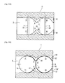
Fig. 8 is a cross-sectional view illustrating the carburetor according to the third embodiment of the present invention. -
Fig. 9 is a cross-sectional perspective view illustrating the carburetor according to the third embodiment. -
Fig. 10A is a cross-sectional view along the X-X line inFig 8 , illustrating the fully closed state. -
Fig. 10B is a cross-sectional view along the X-X line inFig 8 , illustrating the fully opened state. -
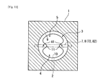
Fig. 11 is a cross-sectional view of the carburetor according to the fourth embodiment of the present invention, facing the side into which intake air flows. -
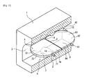
Fig. 12 is a cross-sectional view illustrating the carburetor according to the fifth embodiment of the present invention. -
Fig. 13A is a cross-sectional view of the carburetor according to the fifth embodiment, illustrating the fully closed state. -
Fig. 13B is a cross-sectional view of the carburetor according to the fifth embodiment, illustrating the fully opened state. - Each embodiment of the present invention is described below with reference to the drawings. It should be noted that in the second and later embodiments described below, the same symbols will be used for the same parts and functions as the first embodiment described next and so the description for those parts will be omitted or simplified.
- In
Figs. 1-2 , acarburetor 1 according to this embodiment is used for a stratified scavenging two-stroke engine and is configured to include achoke valve 7 on the upstream side of the air intake flow direction and athrottle valve 8 on the downstream side thereof in anair intake channel 3 provided in the body. On the upstream side of thecarburetor 1 itself, an air filter (not shown) is provided and the downstream side of thecarburetor 1 is attached to the engine via aplastic insulator 20 with heat resistance. The body of thecarburetor 1 and thevalves - Inside the
air intake channel 3 of thecarburetor 1 as such, a nearU-shaped venturi 9 is provided which bulges from the inner periphery of saidair intake channel 3. Theventuri 9 is provided at the section accommodating the lower half of the inner periphery of theair intake channel 3 in the figure, and does not exist in the section accommodating the upper half. The geometry of the opening of theventuri 9 is a near rectangular shape with an upward opening and is thin-walled in the lower section of theventuri 9. It should be noted that the shape of the opening of theventuri 9 is not limited to being rectangular and may be formed as a long hole or a half circle as shown in the two-dot chain line inFig. 1 . - The
venturi 9 is positioned at the middle point between thechoke valve 7 on the upstream side and thethrottle valve 8 on the downstream side. In a part of the opening of the venturi 9 (the lower section in the figure), amain jet 10 is provided as a fuel intake port through which fuel withdrawn from afuel line 2 is injected via the pressure pulsation from the engine. At both ends of theventuri 9, a bulgingportion 11 that bulges inward from theair intake channel 3 is provided. The bulgingportion 11 is provided on both the left and right sides and forms the opening of theventuri 9 with vertical inner portions. - The
valves rotating shafts rotating plates shafts valves valves Fig 2 and inFig. 4 (A) , the rotatingplates venturi 9 with their disk-shaped faces opposed. Additionally, in this state, fuel for idling is injected from a sub-jet (not shown) provided on the downstream side of therotating plate 82. - In contrast, when the
throttle valve 8 is fully opened such as when driving the engine at high revolutions, thechoke valve 7 is naturally in its fully opened position at which therotating plates valves Fig. 1-3 andFig 4(B) ). - At this time, for the
valves rotating plates air intake channel 3, the rotatingplates valves - One of the divided sections in the
air intake channel 3 is the side at which the main jet is provided to become the air-fuel mixture channel 4. The other section in theair intake channel 3 becomes theair channel 5 through which guiding air flows. In other words, according to this embodiment, of thechannels venturi 9 described above is provided to accommodate the air-fuel mixture channel 4. Further, according to this embodiment in which thevalves rotating plates portion 11 at both ends of theventuri 9. - In this case, although the
venturi 9 has the bulgingportion 11 to bulge enough to block region A1, the substantially bulging venturi 9 (the bulging portion 11) never prevents rotation of thevalves venturi 9 is formed as nearly triangular to accommodate region A. - Further, for the bulging
portion 11 whose edge geometry is nearly triangular, the apex is rounded and the oblique sides sandwiching this apex are curved to accommodate the external periphery of therotating plates rotating plates air channel 5 from the air-fuel mixture channel 4 through such a gap because the fuel from themain jet 10 is injected toward the downstream side. - Inside the
air intake channel 3, a pair of plate-shaped bulgingportions 12 are also provided to cover the region A2 formed between thethrottle valve 8 fully opened and theinsulator 20. The geometry of this bulgingportion 12 in a planar view corresponds to the shape created by dividing the bulgingportion 11 of a planar view into two. On the downstream side of the bulgingportion 12 and therotating plate 82, adivider plate 21 provided in theinsulator 20 is opposed. - In this embodiment as such, the air-
fuel mixture channel 4 and theair channel 5 can be divided more securely and the exhaust gas emissions can be enhanced by preventing fuel from getting into theair channel 5 side because regions A1 and A2 are blocked by the bulgingportions valves - Moreover, since the
valves carburetor 1 can be shortened in the direction of air intake flow and size reduction of the entire intake system can be facilitated more. Additionally, since a traditional flow guide element is not required in therotating plate 82 of thethrottle valve 8, thethrottle valve 8 in the traditional simple configuration can be used and a divider plate or partition wall is not required to be constructed separately from theventuri 9, allowing the object of the present invention to be achieved without increasing the number of parts. - Moreover, the bulging
portion 12 shown in theFig 4 can be provided by incorporating into thedivider plate 21 of theinsulator 20 to guide from theinsulator 20 side to thecarburetor 1 side, whereby obtaining an effect in which thecarburetor 1 can be constructed in a way such that the regularair intake channel 3 with theventuri 9 is provided. -
Figs. 5-7 show thecarburetor 1 according to the second embodiment of the present invention. According to this embodiment, theventuri 9 is formed as a continuous circle in the circumferential direction inside theair intake channel 3 and therefore, the bulgingportion 11 formed to be incorporated on the inner diameter side of theventuri 9 is circular, having equal cross-sectional geometry over the entire region in the circumferential direction. As shown inFig. 7 (A) and (B) , the cross-sectional geometry corresponding to region A of the bulgingportion 11 is nearly triangular with a rounded apex, which is nearly the same as the geometry of the edge of the bulgingportion 11 according to the first embodiment. - The opening of the
venturi 9 is a circle. In other words, inside theair intake channel 3 having same diameter dimensions as traditional ones, theventuri 9 with a smaller venturi diameter than traditional ones is provided. It should be noted that the opening of theventuri 9 is not limited to a circle and may be a long hole with longer vertical dimensions or rectangular. In other words, it is a shape created by providing theventuri 9 according to the first embodiment along both the top and bottom. - According to this embodiment above, almost same the effect as the first embodiment can be obtained, such as the gap between the
valves portion 11 of theventuri 9. -
Figs. 8-7 show thecarburetor 1 according to the third embodiment of the present invention. According to this embodiment, the bulgingportion 11 with a geometry bigger than the cross-sectional geometry of thetraditional venturi 9 is provided, and in this regard, it is different from the second embodiment described above. The bulgingportion 11 is plate-shaped, with a pair provided at the position accommodating theventuri 9, opposed in the radial direction. The thickness of the bulgingportion 11 is nearly the same level as the thickness of therotating plates valves Fig 10 (A) and (B) , the geometry of the bulging portion in a planar view is the same as the shape created by joining two of the bulgingportions 12, which is nearly triangular to accommodate region A1. - However, the bulging
portion 11 as such, similar to theventuri 9, may be provided by incorporating into the body of thecarburetor 1 using the same material, or may be constructed separately using plastic, etc. to be assembled into theventuri 9. - Again, in this embodiment described above, not only can region A1 between the
valves portion 11 but also thevalves valves
Also, the opening area of theventuri 9 is not reduced more than required, allowing less air resistance because the bulgingportions -
Fig. 11 shows thecarburetor 1 according to the fourth embodiment of the present invention. In the second embodiment described above, the cross-sectional geometry of theventuri 9, which is also the bulgingportion 11, is uniform in the circumferential direction and theventuri 9 has a relatively small opening area, whereas in this embodiment, the bulgingportion 11 according to this embodiment is formed by increasing the bulging amount continuously only for the part accommodating region A1 and theventuri 9 is formed to be of the same size as traditional ones (same as the third embodiment) for other parts. - In other words, the bulging
portion 11 according to this embodiment is constructed from the bulgingportion 11 in the third embodiment with a gently curved surface continuous toward theventuri 9. In this case, although the cross-sectional geometry of theventuri 9 is not uniform in the circumferential direction and the opening shape is not a circle, the opening area does not need to be made as small as the second embodiment while blocking region A1 well, and it can be constructed in the same way as a regular carburetor. -
Figs. 9-10 show thecarburetor 1 according to the fifth embodiment of the present invention. In this embodiment, the cross-sectional geometry of theair intake channel 3 is half a long hole shape with the side of the flat surface having themain jet 10, whereby the geometry of therotating plates 72 and 78 ofvalves plates arc sections sections valves block sections - Also, when the
valves plates valve 7 and 8) of theair intake channel 3. Therefore, when thevalves air intake channel 3 is again divided into the air-fuel mixture channel 4 at themain jet 10 side and theair channel 5 for guiding air containing no fuel by saidvalves channels - Moreover, in this embodiment, the
venturi 9 is cut so as not to prevent the rotation of thevalves air intake channel 3. In theventuri 9 as such, both ends of the part formed within theair channel 5 are a flat surface and its rotation amount is regulated by theblock sections rotating plates - According to the embodiments above, the
air intake channel 3 can be divided into the air-fuel mixture channel 4 and theair channel 5 only by thevalves valves valves carburetor 1 can be reduced without fail. In addition, it is not required to provide a flow guide element, etc. for each of thevalves - It should be noted that the present invention is not limited to each embodiment described above, and various modifications are included in the present invention within the scope as long as they achieve the objective of the present invention.
For example, although the cross-sectional geometry of theair intake channel 3 is a half long hole shape while the geometry of therotating plates - The carburetor according to the present invention can be employed in a two-stroke engine in a portable operating machine such as a chainsaw, a lawn mower, and an engine blower.
- 1. Carburetor; 3. Air Intake Channel; 4. Air-fuel mixture Channel; 5. Air Channel; 7. Choke Valve; 8. Throttle Valve; 9. Venturi; 10. Main Jet as a fuel port; 11. Bulging Portion; A1. Region; and C. Gap
Claims (4)
- A carburetor comprising a choke valve on the upstream side and a throttle valve on the downstream side inside an air intake channel, wherein:said valves are rotated to their fully opened state to be closely opposing each other;a bulging portion is provided which bulges toward a region between said closely opposing valves on the inner periphery of said air intake channel; andsaid air intake channel is divided into an air-fuel mixture channel at which a fuel intake port is provided and an air channel through which guiding air flows by said valves in said fully opened state and said bulging portion.
- The carburetor of claim 1, wherein:said bulging portion is a venturi provided inside said air intake channel.
- The carburetor of claim 1, wherein:said bulging portion is a plate shape separated from a venturi.
- A carburetor comprising a choke valve on the upstream side and a throttle valve on the downstream side inside an air intake channel, wherein:a gap between closely opposed portions of said valves in their fully opened state is nearly uniformly formed widthwise of said air intake channel; andsaid air intake channel is divided into an air-fuel mixture channel at which a fuel intake port is provided and an air channel through which guiding air flows by said valves in said fully opened state.
Applications Claiming Priority (1)
| Application Number | Priority Date | Filing Date | Title |
|---|---|---|---|
| PCT/JP2009/064577 WO2011021293A1 (en) | 2009-08-20 | 2009-08-20 | Carburetor |
Publications (3)
| Publication Number | Publication Date |
|---|---|
| EP2469055A1 true EP2469055A1 (en) | 2012-06-27 |
| EP2469055A4 EP2469055A4 (en) | 2013-07-24 |
| EP2469055B1 EP2469055B1 (en) | 2017-07-19 |
Family
ID=43606756
Family Applications (1)
| Application Number | Title | Priority Date | Filing Date |
|---|---|---|---|
| EP09848490.0A Active EP2469055B1 (en) | 2009-08-20 | 2009-08-20 | Carburetor |
Country Status (6)
| Country | Link |
|---|---|
| US (1) | US9109542B2 (en) |
| EP (1) | EP2469055B1 (en) |
| JP (1) | JPWO2011021293A1 (en) |
| CN (1) | CN102549247B (en) |
| ES (1) | ES2643552T3 (en) |
| WO (1) | WO2011021293A1 (en) |
Families Citing this family (5)
| Publication number | Priority date | Publication date | Assignee | Title |
|---|---|---|---|---|
| JP6487631B2 (en) | 2014-05-21 | 2019-03-20 | 株式会社やまびこ | Layered scavenging two-cycle internal combustion engine |
| JP6343176B2 (en) * | 2014-05-21 | 2018-06-13 | 株式会社やまびこ | Vaporizer for stratified scavenging two-cycle engine |
| JP6556524B2 (en) * | 2015-06-24 | 2019-08-07 | 株式会社やまびこ | Air cleaner for stratified scavenging two-cycle internal combustion engine |
| US9365257B2 (en) * | 2015-12-11 | 2016-06-14 | Ching-Ho Yeh | Pivot angle setting mechanism |
| EP3943740A1 (en) * | 2020-07-21 | 2022-01-26 | Andreas Stihl AG & Co. KG | Fuel distributor |
Family Cites Families (15)
| Publication number | Priority date | Publication date | Assignee | Title |
|---|---|---|---|---|
| JPS5918533B2 (en) * | 1975-06-24 | 1984-04-27 | 日産自動車株式会社 | Multi-point ignition engine partial cylinder combustion device |
| US4073278A (en) * | 1976-01-16 | 1978-02-14 | Glenn Edward R | Carburator |
| JPS5752347Y2 (en) * | 1979-06-18 | 1982-11-13 | ||
| JPH10110652A (en) * | 1996-10-03 | 1998-04-28 | Zama Japan Kk | Starting fuel supply device for membrane carburetor |
| JP2001295652A (en) * | 2000-04-13 | 2001-10-26 | Zama Japan Kk | Stratified scavenging two-cycle engine |
| US7100551B2 (en) * | 2001-12-10 | 2006-09-05 | Andreas Stihl Ag & Co. Kg | Two-cycle engine with forward scavenging air positioning and single-flow carburetor |
| DE10160539B4 (en) * | 2001-12-10 | 2017-06-08 | Andreas Stihl Ag & Co. | Two-stroke engine with flushing template and single-inlet carburetor |
| US20050016474A1 (en) * | 2003-04-08 | 2005-01-27 | Dopke Russell J. | Intake air and carburetor heating arrangement for V-twin engines |
| GB0426027D0 (en) | 2004-11-26 | 2004-12-29 | Ricardo Uk Ltd | Yet even further improvements to air flow in a split carburettor two stroke engine |
| DE102005003559B4 (en) * | 2005-01-26 | 2014-07-03 | Andreas Stihl Ag & Co. Kg | carburettor |
| DE102005015164B4 (en) | 2005-04-02 | 2014-04-17 | Andreas Stihl Ag & Co. Kg | Two-stroke engine |
| DE102006032475B4 (en) * | 2006-07-13 | 2016-10-20 | Andreas Stihl Ag & Co. Kg | carburettor |
| DE102007037009A1 (en) * | 2006-08-09 | 2008-03-06 | Andreas Stihl Ag & Co. Kg | Heat engine for driving tool of e.g. chain saw, has part of intake duct guided in elastic inlet tube, which has separation wall extending on part of length of tube and dividing intake duct into mixture duct and inlet duct |
| CN101512137B (en) | 2006-09-14 | 2012-01-18 | 胡斯华纳有限公司 | Fuel supply component |
| JP5145133B2 (en) * | 2008-06-26 | 2013-02-13 | 本田技研工業株式会社 | General-purpose engine exhaust gas recirculation structure |
-
2009
- 2009-08-20 CN CN200980161038.4A patent/CN102549247B/en active Active
- 2009-08-20 JP JP2011527524A patent/JPWO2011021293A1/en active Pending
- 2009-08-20 WO PCT/JP2009/064577 patent/WO2011021293A1/en not_active Ceased
- 2009-08-20 EP EP09848490.0A patent/EP2469055B1/en active Active
- 2009-08-20 ES ES09848490.0T patent/ES2643552T3/en active Active
- 2009-08-20 US US13/391,329 patent/US9109542B2/en active Active
Also Published As
| Publication number | Publication date |
|---|---|
| JPWO2011021293A1 (en) | 2013-01-17 |
| CN102549247A (en) | 2012-07-04 |
| US20120146249A1 (en) | 2012-06-14 |
| US9109542B2 (en) | 2015-08-18 |
| CN102549247B (en) | 2015-03-18 |
| EP2469055A4 (en) | 2013-07-24 |
| ES2643552T3 (en) | 2017-11-23 |
| EP2469055B1 (en) | 2017-07-19 |
| WO2011021293A1 (en) | 2011-02-24 |
Similar Documents
| Publication | Publication Date | Title |
|---|---|---|
| EP2469055B1 (en) | Carburetor | |
| US7013851B2 (en) | Intake arrangement | |
| CN108350840B (en) | Intake device for internal combustion engine | |
| JP5715761B2 (en) | Internal combustion engine | |
| EP3480449A1 (en) | Air intake apparatus of multi-cylinder engine | |
| JP2012127348A (en) | Two-cycle engine | |
| US20090194726A1 (en) | Layered scavenging carburetor | |
| US10001067B2 (en) | Carburetor with scavenging fluid flow | |
| CN101131136B (en) | Layered scavenging carburetor | |
| JP6343176B2 (en) | Vaporizer for stratified scavenging two-cycle engine | |
| JP2004124835A (en) | Intake device for internal combustion engine | |
| EP3032065B1 (en) | Air leading type stratified scavenging two-stroke engine and carburetor for same | |
| JP2012127342A (en) | Two-stroke engine | |
| US7963501B2 (en) | Butterfly valve | |
| EP2492486A1 (en) | Stratified scavenging two-cycle engine and carburetor | |
| JP4971242B2 (en) | Intake device for internal combustion engine | |
| JP6009486B2 (en) | Carburetor | |
| US7828272B2 (en) | Carburettor | |
| US20230013645A1 (en) | Fuel feed unit and two-stroke engine having a fuel feed unit | |
| EP1892406B1 (en) | Layered scavenging carburetor | |
| US20080224335A1 (en) | Carburetor for stratified charge two-cycle engine | |
| JPH01187326A (en) | Air fuel mixer for gas engine | |
| US20090218534A1 (en) | Carburettors | |
| JP6504232B1 (en) | Engine intake system | |
| JP2002317637A (en) | Variable intake system for engine |
Legal Events
| Date | Code | Title | Description |
|---|---|---|---|
| PUAI | Public reference made under article 153(3) epc to a published international application that has entered the european phase |
Free format text: ORIGINAL CODE: 0009012 |
|
| 17P | Request for examination filed |
Effective date: 20120315 |
|
| AK | Designated contracting states |
Kind code of ref document: A1 Designated state(s): AT BE BG CH CY CZ DE DK EE ES FI FR GB GR HR HU IE IS IT LI LT LU LV MC MK MT NL NO PL PT RO SE SI SK SM TR |
|
| DAX | Request for extension of the european patent (deleted) | ||
| A4 | Supplementary search report drawn up and despatched |
Effective date: 20130621 |
|
| RIC1 | Information provided on ipc code assigned before grant |
Ipc: F02D 9/10 20060101ALI20130617BHEP Ipc: F02M 19/08 20060101ALI20130617BHEP Ipc: F02M 19/00 20060101ALI20130617BHEP Ipc: F02B 25/22 20060101AFI20130617BHEP |
|
| 17Q | First examination report despatched |
Effective date: 20140403 |
|
| GRAP | Despatch of communication of intention to grant a patent |
Free format text: ORIGINAL CODE: EPIDOSNIGR1 |
|
| INTG | Intention to grant announced |
Effective date: 20170316 |
|
| GRAS | Grant fee paid |
Free format text: ORIGINAL CODE: EPIDOSNIGR3 |
|
| GRAA | (expected) grant |
Free format text: ORIGINAL CODE: 0009210 |
|
| AK | Designated contracting states |
Kind code of ref document: B1 Designated state(s): AT BE BG CH CY CZ DE DK EE ES FI FR GB GR HR HU IE IS IT LI LT LU LV MC MK MT NL NO PL PT RO SE SI SK SM TR |
|
| REG | Reference to a national code |
Ref country code: GB Ref legal event code: FG4D |
|
| REG | Reference to a national code |
Ref country code: CH Ref legal event code: EP |
|
| REG | Reference to a national code |
Ref country code: IE Ref legal event code: FG4D |
|
| REG | Reference to a national code |
Ref country code: AT Ref legal event code: REF Ref document number: 910627 Country of ref document: AT Kind code of ref document: T Effective date: 20170815 |
|
| REG | Reference to a national code |
Ref country code: DE Ref legal event code: R096 Ref document number: 602009047293 Country of ref document: DE |
|
| REG | Reference to a national code |
Ref country code: FR Ref legal event code: PLFP Year of fee payment: 9 |
|
| REG | Reference to a national code |
Ref country code: NL Ref legal event code: MP Effective date: 20170719 |
|
| REG | Reference to a national code |
Ref country code: ES Ref legal event code: FG2A Ref document number: 2643552 Country of ref document: ES Kind code of ref document: T3 Effective date: 20171123 |
|
| REG | Reference to a national code |
Ref country code: LT Ref legal event code: MG4D |
|
| REG | Reference to a national code |
Ref country code: AT Ref legal event code: MK05 Ref document number: 910627 Country of ref document: AT Kind code of ref document: T Effective date: 20170719 |
|
| PG25 | Lapsed in a contracting state [announced via postgrant information from national office to epo] |
Ref country code: NL Free format text: LAPSE BECAUSE OF FAILURE TO SUBMIT A TRANSLATION OF THE DESCRIPTION OR TO PAY THE FEE WITHIN THE PRESCRIBED TIME-LIMIT Effective date: 20170719 Ref country code: NO Free format text: LAPSE BECAUSE OF FAILURE TO SUBMIT A TRANSLATION OF THE DESCRIPTION OR TO PAY THE FEE WITHIN THE PRESCRIBED TIME-LIMIT Effective date: 20171019 Ref country code: SE Free format text: LAPSE BECAUSE OF FAILURE TO SUBMIT A TRANSLATION OF THE DESCRIPTION OR TO PAY THE FEE WITHIN THE PRESCRIBED TIME-LIMIT Effective date: 20170719 Ref country code: HR Free format text: LAPSE BECAUSE OF FAILURE TO SUBMIT A TRANSLATION OF THE DESCRIPTION OR TO PAY THE FEE WITHIN THE PRESCRIBED TIME-LIMIT Effective date: 20170719 Ref country code: LT Free format text: LAPSE BECAUSE OF FAILURE TO SUBMIT A TRANSLATION OF THE DESCRIPTION OR TO PAY THE FEE WITHIN THE PRESCRIBED TIME-LIMIT Effective date: 20170719 Ref country code: AT Free format text: LAPSE BECAUSE OF FAILURE TO SUBMIT A TRANSLATION OF THE DESCRIPTION OR TO PAY THE FEE WITHIN THE PRESCRIBED TIME-LIMIT Effective date: 20170719 |
|
| PG25 | Lapsed in a contracting state [announced via postgrant information from national office to epo] |
Ref country code: LV Free format text: LAPSE BECAUSE OF FAILURE TO SUBMIT A TRANSLATION OF THE DESCRIPTION OR TO PAY THE FEE WITHIN THE PRESCRIBED TIME-LIMIT Effective date: 20170719 Ref country code: GR Free format text: LAPSE BECAUSE OF FAILURE TO SUBMIT A TRANSLATION OF THE DESCRIPTION OR TO PAY THE FEE WITHIN THE PRESCRIBED TIME-LIMIT Effective date: 20171020 Ref country code: BG Free format text: LAPSE BECAUSE OF FAILURE TO SUBMIT A TRANSLATION OF THE DESCRIPTION OR TO PAY THE FEE WITHIN THE PRESCRIBED TIME-LIMIT Effective date: 20171019 Ref country code: PL Free format text: LAPSE BECAUSE OF FAILURE TO SUBMIT A TRANSLATION OF THE DESCRIPTION OR TO PAY THE FEE WITHIN THE PRESCRIBED TIME-LIMIT Effective date: 20170719 Ref country code: IS Free format text: LAPSE BECAUSE OF FAILURE TO SUBMIT A TRANSLATION OF THE DESCRIPTION OR TO PAY THE FEE WITHIN THE PRESCRIBED TIME-LIMIT Effective date: 20171119 |
|
| REG | Reference to a national code |
Ref country code: CH Ref legal event code: PL |
|
| REG | Reference to a national code |
Ref country code: DE Ref legal event code: R097 Ref document number: 602009047293 Country of ref document: DE |
|
| PG25 | Lapsed in a contracting state [announced via postgrant information from national office to epo] |
Ref country code: MC Free format text: LAPSE BECAUSE OF FAILURE TO SUBMIT A TRANSLATION OF THE DESCRIPTION OR TO PAY THE FEE WITHIN THE PRESCRIBED TIME-LIMIT Effective date: 20170719 Ref country code: RO Free format text: LAPSE BECAUSE OF FAILURE TO SUBMIT A TRANSLATION OF THE DESCRIPTION OR TO PAY THE FEE WITHIN THE PRESCRIBED TIME-LIMIT Effective date: 20170719 Ref country code: CZ Free format text: LAPSE BECAUSE OF FAILURE TO SUBMIT A TRANSLATION OF THE DESCRIPTION OR TO PAY THE FEE WITHIN THE PRESCRIBED TIME-LIMIT Effective date: 20170719 Ref country code: CH Free format text: LAPSE BECAUSE OF NON-PAYMENT OF DUE FEES Effective date: 20170831 Ref country code: LI Free format text: LAPSE BECAUSE OF NON-PAYMENT OF DUE FEES Effective date: 20170831 Ref country code: DK Free format text: LAPSE BECAUSE OF FAILURE TO SUBMIT A TRANSLATION OF THE DESCRIPTION OR TO PAY THE FEE WITHIN THE PRESCRIBED TIME-LIMIT Effective date: 20170719 |
|
| PLBE | No opposition filed within time limit |
Free format text: ORIGINAL CODE: 0009261 |
|
| STAA | Information on the status of an ep patent application or granted ep patent |
Free format text: STATUS: NO OPPOSITION FILED WITHIN TIME LIMIT |
|
| REG | Reference to a national code |
Ref country code: IE Ref legal event code: MM4A |
|
| PG25 | Lapsed in a contracting state [announced via postgrant information from national office to epo] |
Ref country code: SK Free format text: LAPSE BECAUSE OF FAILURE TO SUBMIT A TRANSLATION OF THE DESCRIPTION OR TO PAY THE FEE WITHIN THE PRESCRIBED TIME-LIMIT Effective date: 20170719 Ref country code: EE Free format text: LAPSE BECAUSE OF FAILURE TO SUBMIT A TRANSLATION OF THE DESCRIPTION OR TO PAY THE FEE WITHIN THE PRESCRIBED TIME-LIMIT Effective date: 20170719 Ref country code: SM Free format text: LAPSE BECAUSE OF FAILURE TO SUBMIT A TRANSLATION OF THE DESCRIPTION OR TO PAY THE FEE WITHIN THE PRESCRIBED TIME-LIMIT Effective date: 20170719 |
|
| REG | Reference to a national code |
Ref country code: BE Ref legal event code: MM Effective date: 20170831 |
|
| 26N | No opposition filed |
Effective date: 20180420 |
|
| GBPC | Gb: european patent ceased through non-payment of renewal fee |
Effective date: 20171019 |
|
| PG25 | Lapsed in a contracting state [announced via postgrant information from national office to epo] |
Ref country code: LU Free format text: LAPSE BECAUSE OF NON-PAYMENT OF DUE FEES Effective date: 20170820 |
|
| REG | Reference to a national code |
Ref country code: FR Ref legal event code: PLFP Year of fee payment: 10 |
|
| PG25 | Lapsed in a contracting state [announced via postgrant information from national office to epo] |
Ref country code: IE Free format text: LAPSE BECAUSE OF NON-PAYMENT OF DUE FEES Effective date: 20170820 Ref country code: GB Free format text: LAPSE BECAUSE OF NON-PAYMENT OF DUE FEES Effective date: 20171019 |
|
| PG25 | Lapsed in a contracting state [announced via postgrant information from national office to epo] |
Ref country code: BE Free format text: LAPSE BECAUSE OF NON-PAYMENT OF DUE FEES Effective date: 20170831 Ref country code: SI Free format text: LAPSE BECAUSE OF FAILURE TO SUBMIT A TRANSLATION OF THE DESCRIPTION OR TO PAY THE FEE WITHIN THE PRESCRIBED TIME-LIMIT Effective date: 20170719 |
|
| PG25 | Lapsed in a contracting state [announced via postgrant information from national office to epo] |
Ref country code: MT Free format text: LAPSE BECAUSE OF NON-PAYMENT OF DUE FEES Effective date: 20170820 |
|
| PG25 | Lapsed in a contracting state [announced via postgrant information from national office to epo] |
Ref country code: HU Free format text: LAPSE BECAUSE OF FAILURE TO SUBMIT A TRANSLATION OF THE DESCRIPTION OR TO PAY THE FEE WITHIN THE PRESCRIBED TIME-LIMIT; INVALID AB INITIO Effective date: 20090820 |
|
| PG25 | Lapsed in a contracting state [announced via postgrant information from national office to epo] |
Ref country code: CY Free format text: LAPSE BECAUSE OF NON-PAYMENT OF DUE FEES Effective date: 20170719 |
|
| PG25 | Lapsed in a contracting state [announced via postgrant information from national office to epo] |
Ref country code: MK Free format text: LAPSE BECAUSE OF FAILURE TO SUBMIT A TRANSLATION OF THE DESCRIPTION OR TO PAY THE FEE WITHIN THE PRESCRIBED TIME-LIMIT Effective date: 20170719 |
|
| PG25 | Lapsed in a contracting state [announced via postgrant information from national office to epo] |
Ref country code: TR Free format text: LAPSE BECAUSE OF FAILURE TO SUBMIT A TRANSLATION OF THE DESCRIPTION OR TO PAY THE FEE WITHIN THE PRESCRIBED TIME-LIMIT Effective date: 20170719 |
|
| PG25 | Lapsed in a contracting state [announced via postgrant information from national office to epo] |
Ref country code: PT Free format text: LAPSE BECAUSE OF FAILURE TO SUBMIT A TRANSLATION OF THE DESCRIPTION OR TO PAY THE FEE WITHIN THE PRESCRIBED TIME-LIMIT Effective date: 20170719 |
|
| PGFP | Annual fee paid to national office [announced via postgrant information from national office to epo] |
Ref country code: IT Payment date: 20210607 Year of fee payment: 13 |
|
| PGFP | Annual fee paid to national office [announced via postgrant information from national office to epo] |
Ref country code: FI Payment date: 20210727 Year of fee payment: 13 Ref country code: FR Payment date: 20210708 Year of fee payment: 13 |
|
| PGFP | Annual fee paid to national office [announced via postgrant information from national office to epo] |
Ref country code: ES Payment date: 20210916 Year of fee payment: 13 |
|
| PG25 | Lapsed in a contracting state [announced via postgrant information from national office to epo] |
Ref country code: FI Free format text: LAPSE BECAUSE OF NON-PAYMENT OF DUE FEES Effective date: 20220820 |
|
| PG25 | Lapsed in a contracting state [announced via postgrant information from national office to epo] |
Ref country code: IT Free format text: LAPSE BECAUSE OF NON-PAYMENT OF DUE FEES Effective date: 20220820 Ref country code: FR Free format text: LAPSE BECAUSE OF NON-PAYMENT OF DUE FEES Effective date: 20220831 |
|
| REG | Reference to a national code |
Ref country code: ES Ref legal event code: FD2A Effective date: 20230929 |
|
| PG25 | Lapsed in a contracting state [announced via postgrant information from national office to epo] |
Ref country code: ES Free format text: LAPSE BECAUSE OF NON-PAYMENT OF DUE FEES Effective date: 20220821 |
|
| PGFP | Annual fee paid to national office [announced via postgrant information from national office to epo] |
Ref country code: DE Payment date: 20250708 Year of fee payment: 17 |