EP2469035A2 - Turbine engine component comprising a leading edge airfoil-to-platform fillet cooling tube - Google Patents
Turbine engine component comprising a leading edge airfoil-to-platform fillet cooling tube Download PDFInfo
- Publication number
- EP2469035A2 EP2469035A2 EP11250867A EP11250867A EP2469035A2 EP 2469035 A2 EP2469035 A2 EP 2469035A2 EP 11250867 A EP11250867 A EP 11250867A EP 11250867 A EP11250867 A EP 11250867A EP 2469035 A2 EP2469035 A2 EP 2469035A2
- Authority
- EP
- European Patent Office
- Prior art keywords
- leading edge
- turbine engine
- engine component
- boxcar
- cooling tube
- Prior art date
- Legal status (The legal status is an assumption and is not a legal conclusion. Google has not performed a legal analysis and makes no representation as to the accuracy of the status listed.)
- Granted
Links
- 238000001816 cooling Methods 0.000 title claims abstract description 46
- 229910010293 ceramic material Inorganic materials 0.000 claims description 2
- 239000012809 cooling fluid Substances 0.000 claims 1
- 239000002184 metal Substances 0.000 description 4
- 230000001419 dependent effect Effects 0.000 description 2
- 239000000203 mixture Substances 0.000 description 2
- 238000012986 modification Methods 0.000 description 2
- 230000004048 modification Effects 0.000 description 2
- 238000005266 casting Methods 0.000 description 1
- 239000002826 coolant Substances 0.000 description 1
- 238000010438 heat treatment Methods 0.000 description 1
- 230000003647 oxidation Effects 0.000 description 1
- 238000007254 oxidation reaction Methods 0.000 description 1
Images

Classifications
-
- F—MECHANICAL ENGINEERING; LIGHTING; HEATING; WEAPONS; BLASTING
- F01—MACHINES OR ENGINES IN GENERAL; ENGINE PLANTS IN GENERAL; STEAM ENGINES
- F01D—NON-POSITIVE DISPLACEMENT MACHINES OR ENGINES, e.g. STEAM TURBINES
- F01D9/00—Stators
- F01D9/02—Nozzles; Nozzle boxes; Stator blades; Guide conduits, e.g. individual nozzles
- F01D9/04—Nozzles; Nozzle boxes; Stator blades; Guide conduits, e.g. individual nozzles forming ring or sector
- F01D9/041—Nozzles; Nozzle boxes; Stator blades; Guide conduits, e.g. individual nozzles forming ring or sector using blades
-
- B—PERFORMING OPERATIONS; TRANSPORTING
- B22—CASTING; POWDER METALLURGY
- B22C—FOUNDRY MOULDING
- B22C9/00—Moulds or cores; Moulding processes
- B22C9/10—Cores; Manufacture or installation of cores
-
- F—MECHANICAL ENGINEERING; LIGHTING; HEATING; WEAPONS; BLASTING
- F01—MACHINES OR ENGINES IN GENERAL; ENGINE PLANTS IN GENERAL; STEAM ENGINES
- F01D—NON-POSITIVE DISPLACEMENT MACHINES OR ENGINES, e.g. STEAM TURBINES
- F01D5/00—Blades; Blade-carrying members; Heating, heat-insulating, cooling or antivibration means on the blades or the members
- F01D5/12—Blades
- F01D5/14—Form or construction
- F01D5/18—Hollow blades, i.e. blades with cooling or heating channels or cavities; Heating, heat-insulating or cooling means on blades
- F01D5/186—Film cooling
-
- F—MECHANICAL ENGINEERING; LIGHTING; HEATING; WEAPONS; BLASTING
- F01—MACHINES OR ENGINES IN GENERAL; ENGINE PLANTS IN GENERAL; STEAM ENGINES
- F01D—NON-POSITIVE DISPLACEMENT MACHINES OR ENGINES, e.g. STEAM TURBINES
- F01D5/00—Blades; Blade-carrying members; Heating, heat-insulating, cooling or antivibration means on the blades or the members
- F01D5/12—Blades
- F01D5/14—Form or construction
- F01D5/18—Hollow blades, i.e. blades with cooling or heating channels or cavities; Heating, heat-insulating or cooling means on blades
- F01D5/187—Convection cooling
-
- F—MECHANICAL ENGINEERING; LIGHTING; HEATING; WEAPONS; BLASTING
- F01—MACHINES OR ENGINES IN GENERAL; ENGINE PLANTS IN GENERAL; STEAM ENGINES
- F01D—NON-POSITIVE DISPLACEMENT MACHINES OR ENGINES, e.g. STEAM TURBINES
- F01D9/00—Stators
- F01D9/06—Fluid supply conduits to nozzles or the like
- F01D9/065—Fluid supply or removal conduits traversing the working fluid flow, e.g. for lubrication-, cooling-, or sealing fluids
-
- F—MECHANICAL ENGINEERING; LIGHTING; HEATING; WEAPONS; BLASTING
- F05—INDEXING SCHEMES RELATING TO ENGINES OR PUMPS IN VARIOUS SUBCLASSES OF CLASSES F01-F04
- F05D—INDEXING SCHEME FOR ASPECTS RELATING TO NON-POSITIVE-DISPLACEMENT MACHINES OR ENGINES, GAS-TURBINES OR JET-PROPULSION PLANTS
- F05D2240/00—Components
- F05D2240/10—Stators
- F05D2240/12—Fluid guiding means, e.g. vanes
- F05D2240/121—Fluid guiding means, e.g. vanes related to the leading edge of a stator vane
-
- F—MECHANICAL ENGINEERING; LIGHTING; HEATING; WEAPONS; BLASTING
- F05—INDEXING SCHEMES RELATING TO ENGINES OR PUMPS IN VARIOUS SUBCLASSES OF CLASSES F01-F04
- F05D—INDEXING SCHEME FOR ASPECTS RELATING TO NON-POSITIVE-DISPLACEMENT MACHINES OR ENGINES, GAS-TURBINES OR JET-PROPULSION PLANTS
- F05D2240/00—Components
- F05D2240/80—Platforms for stationary or moving blades
- F05D2240/81—Cooled platforms
-
- F—MECHANICAL ENGINEERING; LIGHTING; HEATING; WEAPONS; BLASTING
- F05—INDEXING SCHEMES RELATING TO ENGINES OR PUMPS IN VARIOUS SUBCLASSES OF CLASSES F01-F04
- F05D—INDEXING SCHEME FOR ASPECTS RELATING TO NON-POSITIVE-DISPLACEMENT MACHINES OR ENGINES, GAS-TURBINES OR JET-PROPULSION PLANTS
- F05D2250/00—Geometry
- F05D2250/10—Two-dimensional
- F05D2250/11—Two-dimensional triangular
-
- F—MECHANICAL ENGINEERING; LIGHTING; HEATING; WEAPONS; BLASTING
- F05—INDEXING SCHEMES RELATING TO ENGINES OR PUMPS IN VARIOUS SUBCLASSES OF CLASSES F01-F04
- F05D—INDEXING SCHEME FOR ASPECTS RELATING TO NON-POSITIVE-DISPLACEMENT MACHINES OR ENGINES, GAS-TURBINES OR JET-PROPULSION PLANTS
- F05D2250/00—Geometry
- F05D2250/20—Three-dimensional
- F05D2250/23—Three-dimensional prismatic
-
- F—MECHANICAL ENGINEERING; LIGHTING; HEATING; WEAPONS; BLASTING
- F05—INDEXING SCHEMES RELATING TO ENGINES OR PUMPS IN VARIOUS SUBCLASSES OF CLASSES F01-F04
- F05D—INDEXING SCHEME FOR ASPECTS RELATING TO NON-POSITIVE-DISPLACEMENT MACHINES OR ENGINES, GAS-TURBINES OR JET-PROPULSION PLANTS
- F05D2250/00—Geometry
- F05D2250/20—Three-dimensional
- F05D2250/27—Three-dimensional hyperboloid
-
- F—MECHANICAL ENGINEERING; LIGHTING; HEATING; WEAPONS; BLASTING
- F05—INDEXING SCHEMES RELATING TO ENGINES OR PUMPS IN VARIOUS SUBCLASSES OF CLASSES F01-F04
- F05D—INDEXING SCHEME FOR ASPECTS RELATING TO NON-POSITIVE-DISPLACEMENT MACHINES OR ENGINES, GAS-TURBINES OR JET-PROPULSION PLANTS
- F05D2250/00—Geometry
- F05D2250/30—Arrangement of components
- F05D2250/32—Arrangement of components according to their shape
- F05D2250/323—Arrangement of components according to their shape convergent
-
- F—MECHANICAL ENGINEERING; LIGHTING; HEATING; WEAPONS; BLASTING
- F05—INDEXING SCHEMES RELATING TO ENGINES OR PUMPS IN VARIOUS SUBCLASSES OF CLASSES F01-F04
- F05D—INDEXING SCHEME FOR ASPECTS RELATING TO NON-POSITIVE-DISPLACEMENT MACHINES OR ENGINES, GAS-TURBINES OR JET-PROPULSION PLANTS
- F05D2250/00—Geometry
- F05D2250/30—Arrangement of components
- F05D2250/32—Arrangement of components according to their shape
- F05D2250/324—Arrangement of components according to their shape divergent
Definitions
- the present disclosure relates to a cooling tube in the vicinity of the leading edge of a turbine engine component at the outer diameter airfoil-to-platform fillet and a casting core for forming same.
- Vanes can be subjected to severe heating conditions in the region of the fillet which extends from the leading edge of the airfoil to the platform. Increased metal temperatures in this region can lead to thermal strains and reduced part life.
- a turbine engine component which broadly comprises an airfoil portion having a leading edge, a platform, a leading edge airfoil to platform fillet, and a cooling tube located within said fillet, which cooling tube has a flared entrance end and a flared exit end.
- a core for forming part of a turbine engine component which core broadly comprises a first portion for forming an internal cavity within an airfoil portion of said component, a second portion for forming a leading edge boxcar in a leading edge of said airfoil portion, and a third portion for forming a cooling tube which extends between said leading edge boxcar and said internal cavity, which third portion has a flared entrance end and a flared exit end.
- leading edge airfoil-to-platform fillet cooling tube is set forth in the following detailed description and the following drawings wherein like reference numerals depict like elements.
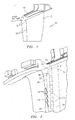
- Fig. 1 illustrates a turbine engine component 10, in particular a turbine vane.
- the component 10 has an airfoil portion 12 and a platform 14.
- the airfoil portion 12 is joined to the platform 14 by an outer diameter fillet 16 at the leading edge 18 of the airfoil portion 12.
- the outer diameter fillet 16 was uncooled due to geometry constraints of the impingement cavity, preventing impingement heat transfer from occurring and also preventing film holes from being drilled through the fillet.
- a new design feature has been developed that provides convective heat transfer to the outer diameter fillet 16.
- Fig. 2 illustrates a cooling configuration for the turbine engine component 10 which is comprised of three separate impingement cavities 20, also known as boxcars.
- impingement cavities 20 also known as boxcars.
- crossover holes 22 in the impingement rib 24 are designed to maximize heat transfer at the nose 26 of the leading edge 18.
- Film cooling holes 28 are drilled into the leading edge impingement cavity as an additional means for cooling the airfoil portion 12.
- the new design feature comprises a fillet cooling tube 30.
- the cooling tube 30 connects the outer diameter of the leading edge boxcar 20 to the leading edge feed cavity 34.
- the cross sectional area of the cooling tube 30 is to be between 25% and 100% of the cross sectional area of the impingement cavity/boxcar 20 to ensure adequate coolant velocity in the cooling tube.
- the ends 31 and 33 of the cooling tube 30 flare out at a blend radius 36 at the junction to the boxcar 20 and the feed cavity 34. This bellmouth shape at the entrance and exit ends 31 and 33 of the tube 30 helps to minimize pressure losses of the cooling air through the cooling tube 30.
- the cross-sectional shape of the cooling tube 30 is dependent on the cross-sectional shape of the boxcar 20 to which it is connected. Since cooling holes are drilled into the outer diameter leading edge boxcar 20, a pressure ratio exists across the fillet cooling tube 30, allowing cooling air to travel from the feed cavity 34 to the leading edge boxcar 30. The cooling air convectively cools the airfoil-to-platform fillet 16, reducing metal temperature and increasing part life.
- a core 60 which may be used to form the leading edge boxcar(s) 20, the cavity 34 internal to the airfoil portion, and the cooling tube 30.
- the core 60 may be formed from a ceramic material.
- the core has a first portion 62 which forms the interior cavity 34, a leading edge portion 64 which forms the leading edge boxcar 20, a plurality of shaped portions 66 which form the cross-over holes, and an arcuate portion 68 which forms the fillet cooling tube.
- the portion 68 has two bellmouth shaped end portions 70 and 72 which form the entrance and exit ends of the fillet cooling tube 30.
- the fillet cooling tube 30 described herein will provide convective heat transfer in the outer diameter leading edge airfoil-to-platform fillet 16, reducing metal temperatures.
- the impingement cavity 20 to which the fillet cooling tube is connected needs film holes 28 or other cooling features that promote a positive pressure ratio from the feed cavity 34 to the impingement cavity 20.
- the ends 31 and 33 of the fillet cooling tube 30 are flared at the junction to the boxcar 20 and the feed cavity 34 to minimize cooling flow pressure losses as cooling air moves through the tube 30.
- the blend radius of the flare is determined by the specific shape of the boxcar support tube.
- the cross-sectional shape of the fillet cooling tube 30 is dependent on the cross-sectional shape of the impingement cavity (boxcar) it is connecting to.
- the cross sectional shape of the tube 30 may be circular, elliptical, triangular, or square.
Landscapes
- Engineering & Computer Science (AREA)
- Mechanical Engineering (AREA)
- General Engineering & Computer Science (AREA)
- Physics & Mathematics (AREA)
- Fluid Mechanics (AREA)
- Turbine Rotor Nozzle Sealing (AREA)
Abstract
Description
- The subject matter described herein was made with government support under Contract No. N00019-02-C-3003 awarded by the Department of the Navy. The government of the United States of America may have rights to the subject matter described herein.
- The present disclosure relates to a cooling tube in the vicinity of the leading edge of a turbine engine component at the outer diameter airfoil-to-platform fillet and a casting core for forming same.
- Vanes can be subjected to severe heating conditions in the region of the fillet which extends from the leading edge of the airfoil to the platform. Increased metal temperatures in this region can lead to thermal strains and reduced part life.
- The prior technology for forming impingement cavities in vanes has not incorporated features that adequately cool the airfoil-to-platform fillet radius.
- Accordingly, it is desirable to reduce metal temperatures in the leading edge outer diameter airfoil-to-platform fillet so as to reduce thermal strains and increase part life. Described herein is a way to cool this region using convective cooling.
- In accordance with the present disclosure, there is provided a turbine engine component which broadly comprises an airfoil portion having a leading edge, a platform, a leading edge airfoil to platform fillet, and a cooling tube located within said fillet, which cooling tube has a flared entrance end and a flared exit end.
- Further in accordance with the present disclosure, there is provided a core for forming part of a turbine engine component, which core broadly comprises a first portion for forming an internal cavity within an airfoil portion of said component, a second portion for forming a leading edge boxcar in a leading edge of said airfoil portion, and a third portion for forming a cooling tube which extends between said leading edge boxcar and said internal cavity, which third portion has a flared entrance end and a flared exit end.
- Other details of the leading edge airfoil-to-platform fillet cooling tube are set forth in the following detailed description and the following drawings wherein like reference numerals depict like elements.
-
-
Fig. 1 is a schematic illustration of a turbine vane having a leading edge airfoil-to-platform fillet; -
Fig. 2 is a schematic illustration of a turbine vane having a fillet cooling tube in accordance with the present invention; -
Fig. 3 is a schematic illustration of a core used to form the fillet cooling tube ofFig. 2 ; -
Fig. 4 is a sectional view taken along lines 4-4 inFig. 3 ; and -
Fig. 5 is a sectional view taken along lines 5-5 inFig. 3 . -
Fig. 1 illustrates aturbine engine component 10, in particular a turbine vane. Thecomponent 10 has anairfoil portion 12 and aplatform 14. Theairfoil portion 12 is joined to theplatform 14 by anouter diameter fillet 16 at the leadingedge 18 of theairfoil portion 12. In previous designs, theouter diameter fillet 16 was uncooled due to geometry constraints of the impingement cavity, preventing impingement heat transfer from occurring and also preventing film holes from being drilled through the fillet. As described herein, a new design feature has been developed that provides convective heat transfer to theouter diameter fillet 16. -
Fig. 2 illustrates a cooling configuration for theturbine engine component 10 which is comprised of threeseparate impingement cavities 20, also known as boxcars. In order to achieve a desirable oxidation life for the leadingedge 18,crossover holes 22 in theimpingement rib 24 are designed to maximize heat transfer at thenose 26 of the leadingedge 18.Film cooling holes 28 are drilled into the leading edge impingement cavity as an additional means for cooling theairfoil portion 12. - The new design feature comprises a
fillet cooling tube 30. Thecooling tube 30 connects the outer diameter of the leadingedge boxcar 20 to the leadingedge feed cavity 34. The cross sectional area of thecooling tube 30 is to be between 25% and 100% of the cross sectional area of the impingement cavity/boxcar 20 to ensure adequate coolant velocity in the cooling tube. Theends cooling tube 30 flare out at ablend radius 36 at the junction to theboxcar 20 and thefeed cavity 34. This bellmouth shape at the entrance andexit ends tube 30 helps to minimize pressure losses of the cooling air through thecooling tube 30. - The cross-sectional shape of the
cooling tube 30 is dependent on the cross-sectional shape of theboxcar 20 to which it is connected. Since cooling holes are drilled into the outer diameter leadingedge boxcar 20, a pressure ratio exists across thefillet cooling tube 30, allowing cooling air to travel from thefeed cavity 34 to the leadingedge boxcar 30. The cooling air convectively cools the airfoil-to-platform fillet 16, reducing metal temperature and increasing part life. - By adding an additional flow path for cooling air, additional internal cooling is achieved in a critical region.
- Referring now to
Figs. 3 to 5 , there is shown acore 60 which may be used to form the leading edge boxcar(s) 20, thecavity 34 internal to the airfoil portion, and thecooling tube 30. Thecore 60 may be formed from a ceramic material. As can be seen fromFig. 3 , the core has afirst portion 62 which forms theinterior cavity 34, a leadingedge portion 64 which forms the leadingedge boxcar 20, a plurality ofshaped portions 66 which form the cross-over holes, and anarcuate portion 68 which forms the fillet cooling tube. As can be seen fromFig. 3 , theportion 68 has two bellmouth shapedend portions fillet cooling tube 30. - The
fillet cooling tube 30 described herein will provide convective heat transfer in the outer diameter leading edge airfoil-to-platform fillet 16, reducing metal temperatures. - The
impingement cavity 20 to which the fillet cooling tube is connected needsfilm holes 28 or other cooling features that promote a positive pressure ratio from thefeed cavity 34 to theimpingement cavity 20. - As noted above, the
ends fillet cooling tube 30 are flared at the junction to theboxcar 20 and thefeed cavity 34 to minimize cooling flow pressure losses as cooling air moves through thetube 30. The blend radius of the flare is determined by the specific shape of the boxcar support tube. - The cross-sectional shape of the
fillet cooling tube 30 is dependent on the cross-sectional shape of the impingement cavity (boxcar) it is connecting to. The cross sectional shape of thetube 30 may be circular, elliptical, triangular, or square. - There has been provided herein a leading edge airfoil-to-platform fillet cooling tube. While the cooling tube has been described in the context of a specific embodiment thereof, other unforeseen alternatives, modifications, or variations may become apparent to those skilled in the art having read the foregoing description. Accordingly, it is intended to embraces those alternatives, modifications, and variations as fall within the broad scope of the appended claims.
Claims (13)
- A turbine engine component (10) comprising:an airfoil portion (12) having a leading edge (18);a platform (14);a leading edge airfoil to platform fillet (16); anda cooling tube (30) located within said fillet (16), said cooling tube having a flared entrance end (31) and a flared exit end (33).
- The turbine engine component of claim 1, wherein said entrance end (31) and said exit end (33) are each bellmouth shaped.
- The turbine engine component of claim 1 or claim 2, wherein said leading edge (18) of said airfoil portion (12) includes a leading edge boxcar (20) and an interior portion of said airfoil portion includes a cavity (34) through which cooling air flows.
- The turbine engine component of claim 3, further comprising a plurality of cross-over holes (22) for allowing cooling fluid to flow from said cavity (34) to said boxcar (20).
- The turbine engine component of claim 3 or claim 4, wherein said boxcar (20) has a plurality of cooling film holes (28).
- The turbine engine component of any preceding claim, wherein said tube (30) has a cross-sectional area which is between 25% and 100% of a cross-sectional area of said boxcar (20).
- The turbine engine component of any preceding claim, wherein said tube (30) has a cross-sectional area which is between 50% and 100% of a cross-sectional area of said boxcar (20).
- The turbine engine component of any preceding claim, wherein said tube (30) has a cross-sectional shape selected from the group consisting of circular, elliptical, triangular, and square.
- The turbine engine component of any preceding claim, wherein said cooling tube (30 meets said leading edge boxcar (20) at an end of said leading edge boxcar (20).
- A core (60) for forming part of a turbine engine component (10), said core comprising:a first portion (62) for forming an internal cavity (34) within an airfoil portion of said component (10);a second portion (64) for forming a leading edge boxcar (20) in a leading edge of said airfoil portion;a third portion (68) for forming a cooling tube (30) which extends between said leading edge boxcar (20) and said internal cavity (34); andsaid third portion (68) having a flared entrance end (70) and a flared exit end (72).
- The core according to claim 10, wherein said core (60) is formed from a ceramic material.
- The core according to claim 10 or claim 11, wherein said core (60) has at least one fourth portion (66) adapted to form at least one cross-over hole (22) between said leading edge boxcar (20) and said cavity (34).
- The core according to any of claims 10 to 12, wherein said entrance end (70) and said exit end (72) are each bellmouthed shaped.
Applications Claiming Priority (1)
| Application Number | Priority Date | Filing Date | Title |
|---|---|---|---|
| US12/977,418 US20120163993A1 (en) | 2010-12-23 | 2010-12-23 | Leading edge airfoil-to-platform fillet cooling tube |
Publications (3)
| Publication Number | Publication Date |
|---|---|
| EP2469035A2 true EP2469035A2 (en) | 2012-06-27 |
| EP2469035A3 EP2469035A3 (en) | 2017-12-13 |
| EP2469035B1 EP2469035B1 (en) | 2020-04-01 |
Family
ID=45001667
Family Applications (1)
| Application Number | Title | Priority Date | Filing Date |
|---|---|---|---|
| EP11250867.6A Active EP2469035B1 (en) | 2010-12-23 | 2011-10-21 | Turbine engine component comprising a leading edge airfoil-to-platform fillet cooling tube |
Country Status (2)
| Country | Link |
|---|---|
| US (1) | US20120163993A1 (en) |
| EP (1) | EP2469035B1 (en) |
Cited By (1)
| Publication number | Priority date | Publication date | Assignee | Title |
|---|---|---|---|---|
| EP3415250A1 (en) * | 2017-06-15 | 2018-12-19 | Siemens Aktiengesellschaft | Casting core with crossover bridge |
Families Citing this family (13)
| Publication number | Priority date | Publication date | Assignee | Title |
|---|---|---|---|---|
| US9528379B2 (en) * | 2013-10-23 | 2016-12-27 | General Electric Company | Turbine bucket having serpentine core |
| US9376927B2 (en) | 2013-10-23 | 2016-06-28 | General Electric Company | Turbine nozzle having non-axisymmetric endwall contour (EWC) |
| US9551226B2 (en) | 2013-10-23 | 2017-01-24 | General Electric Company | Turbine bucket with endwall contour and airfoil profile |
| US9797258B2 (en) | 2013-10-23 | 2017-10-24 | General Electric Company | Turbine bucket including cooling passage with turn |
| US9638041B2 (en) | 2013-10-23 | 2017-05-02 | General Electric Company | Turbine bucket having non-axisymmetric base contour |
| US9347320B2 (en) | 2013-10-23 | 2016-05-24 | General Electric Company | Turbine bucket profile yielding improved throat |
| US9670784B2 (en) | 2013-10-23 | 2017-06-06 | General Electric Company | Turbine bucket base having serpentine cooling passage with leading edge cooling |
| JP5717904B1 (en) * | 2014-08-04 | 2015-05-13 | 三菱日立パワーシステムズ株式会社 | Stator blade, gas turbine, split ring, stator blade remodeling method, and split ring remodeling method |
| US10612392B2 (en) | 2014-12-18 | 2020-04-07 | United Technologies Corporation | Gas turbine engine component with conformal fillet cooling path |
| US10378371B2 (en) * | 2014-12-18 | 2019-08-13 | United Technologies Corporation | Anti-rotation vane |
| US10107108B2 (en) | 2015-04-29 | 2018-10-23 | General Electric Company | Rotor blade having a flared tip |
| US10612394B2 (en) * | 2017-07-21 | 2020-04-07 | United Technologies Corporation | Airfoil having serpentine core resupply flow control |
| KR101937586B1 (en) * | 2017-09-12 | 2019-01-10 | 두산중공업 주식회사 | Vane of turbine, turbine and gas turbine comprising it |
Family Cites Families (11)
| Publication number | Priority date | Publication date | Assignee | Title |
|---|---|---|---|---|
| US5245821A (en) * | 1991-10-21 | 1993-09-21 | General Electric Company | Stator to rotor flow inducer |
| US5340278A (en) * | 1992-11-24 | 1994-08-23 | United Technologies Corporation | Rotor blade with integral platform and a fillet cooling passage |
| US7217094B2 (en) * | 2004-10-18 | 2007-05-15 | United Technologies Corporation | Airfoil with large fillet and micro-circuit cooling |
| US7249933B2 (en) * | 2005-01-10 | 2007-07-31 | General Electric Company | Funnel fillet turbine stage |
| US7632071B2 (en) * | 2005-12-15 | 2009-12-15 | United Technologies Corporation | Cooled turbine blade |
| US7927073B2 (en) * | 2007-01-04 | 2011-04-19 | Siemens Energy, Inc. | Advanced cooling method for combustion turbine airfoil fillets |
| US7621718B1 (en) * | 2007-03-28 | 2009-11-24 | Florida Turbine Technologies, Inc. | Turbine vane with leading edge fillet region impingement cooling |
| ES2442873T3 (en) * | 2008-03-31 | 2014-02-14 | Alstom Technology Ltd | Aerodynamic gas turbine profile |
| US8172533B2 (en) * | 2008-05-14 | 2012-05-08 | United Technologies Corporation | Turbine blade internal cooling configuration |
| GB0811391D0 (en) * | 2008-06-23 | 2008-07-30 | Rolls Royce Plc | A rotor blade |
| US8794906B1 (en) * | 2010-06-22 | 2014-08-05 | Florida Turbine Technologies, Inc. | Turbine stator vane with endwall cooling |
-
2010
- 2010-12-23 US US12/977,418 patent/US20120163993A1/en not_active Abandoned
-
2011
- 2011-10-21 EP EP11250867.6A patent/EP2469035B1/en active Active
Non-Patent Citations (1)
| Title |
|---|
| None |
Cited By (1)
| Publication number | Priority date | Publication date | Assignee | Title |
|---|---|---|---|---|
| EP3415250A1 (en) * | 2017-06-15 | 2018-12-19 | Siemens Aktiengesellschaft | Casting core with crossover bridge |
Also Published As
| Publication number | Publication date |
|---|---|
| EP2469035A3 (en) | 2017-12-13 |
| EP2469035B1 (en) | 2020-04-01 |
| US20120163993A1 (en) | 2012-06-28 |
Similar Documents
| Publication | Publication Date | Title |
|---|---|---|
| EP2469035B1 (en) | Turbine engine component comprising a leading edge airfoil-to-platform fillet cooling tube | |
| EP1600604B1 (en) | Cooler rotor blade and method for cooling a rotor blade | |
| US7841828B2 (en) | Turbine airfoil with submerged endwall cooling channel | |
| EP2369135B1 (en) | Blade outer air seal for a gas turbine engine and corresponding gas turbine engine | |
| EP2860359B1 (en) | Arrangement for cooling a component in the hot gas path of a gas turbine | |
| US8714909B2 (en) | Platform with cooling circuit | |
| US9051943B2 (en) | Gas turbine engine heat exchanger fins with periodic gaps | |
| EP3184745B1 (en) | Multi-wall blade with cooling circuit | |
| EP1607578B1 (en) | Cooled rotor blade | |
| US20140023497A1 (en) | Cooled turbine blade tip shroud with film/purge holes | |
| US9328616B2 (en) | Film-cooled turbine blade for a turbomachine | |
| JP4929097B2 (en) | Gas turbine blade | |
| US20180135423A1 (en) | Double impingement slot cap assembly | |
| EP2597260B1 (en) | Bucket assembly for turbine system | |
| EP2597263A1 (en) | Bucket assembly for turbine system | |
| US9822646B2 (en) | Turbine airfoil cooling system with spanwise extending fins | |
| US8714927B1 (en) | Microcircuit skin core cut back to reduce microcircuit trailing edge stresses | |
| CN104884741B (en) | Blade for turbine | |
| EP3828383A1 (en) | Airfoil with trailing edge cooling circuit | |
| US20150260102A1 (en) | Heat exchanger for a turbo engine | |
| US6824352B1 (en) | Vane enhanced trailing edge cooling design | |
| US10612396B2 (en) | Mechanical component | |
| US10920610B2 (en) | Casting plug with flow control features | |
| EP2754857A1 (en) | Cooling configuration, corresponding stator heat shield, blade, and vane for a gas turbine | |
| EP3121377A1 (en) | Turbine rotors including turbine blades having turbulator cooled tip pockets |
Legal Events
| Date | Code | Title | Description |
|---|---|---|---|
| AK | Designated contracting states |
Kind code of ref document: A2 Designated state(s): AL AT BE BG CH CY CZ DE DK EE ES FI FR GB GR HR HU IE IS IT LI LT LU LV MC MK MT NL NO PL PT RO RS SE SI SK SM TR |
|
| AX | Request for extension of the european patent |
Extension state: BA ME |
|
| PUAI | Public reference made under article 153(3) epc to a published international application that has entered the european phase |
Free format text: ORIGINAL CODE: 0009012 |
|
| RAP1 | Party data changed (applicant data changed or rights of an application transferred) |
Owner name: UNITED TECHNOLOGIES CORPORATION |
|
| PUAL | Search report despatched |
Free format text: ORIGINAL CODE: 0009013 |
|
| AK | Designated contracting states |
Kind code of ref document: A3 Designated state(s): AL AT BE BG CH CY CZ DE DK EE ES FI FR GB GR HR HU IE IS IT LI LT LU LV MC MK MT NL NO PL PT RO RS SE SI SK SM TR |
|
| AX | Request for extension of the european patent |
Extension state: BA ME |
|
| RIC1 | Information provided on ipc code assigned before grant |
Ipc: F01D 9/04 20060101AFI20171103BHEP Ipc: F01D 5/18 20060101ALI20171103BHEP |
|
| STAA | Information on the status of an ep patent application or granted ep patent |
Free format text: STATUS: REQUEST FOR EXAMINATION WAS MADE |
|
| 17P | Request for examination filed |
Effective date: 20180613 |
|
| RBV | Designated contracting states (corrected) |
Designated state(s): AL AT BE BG CH CY CZ DE DK EE ES FI FR GB GR HR HU IE IS IT LI LT LU LV MC MK MT NL NO PL PT RO RS SE SI SK SM TR |
|
| GRAP | Despatch of communication of intention to grant a patent |
Free format text: ORIGINAL CODE: EPIDOSNIGR1 |
|
| STAA | Information on the status of an ep patent application or granted ep patent |
Free format text: STATUS: GRANT OF PATENT IS INTENDED |
|
| INTG | Intention to grant announced |
Effective date: 20191011 |
|
| GRAS | Grant fee paid |
Free format text: ORIGINAL CODE: EPIDOSNIGR3 |
|
| GRAA | (expected) grant |
Free format text: ORIGINAL CODE: 0009210 |
|
| STAA | Information on the status of an ep patent application or granted ep patent |
Free format text: STATUS: THE PATENT HAS BEEN GRANTED |
|
| AK | Designated contracting states |
Kind code of ref document: B1 Designated state(s): AL AT BE BG CH CY CZ DE DK EE ES FI FR GB GR HR HU IE IS IT LI LT LU LV MC MK MT NL NO PL PT RO RS SE SI SK SM TR |
|
| REG | Reference to a national code |
Ref country code: GB Ref legal event code: FG4D |
|
| REG | Reference to a national code |
Ref country code: CH Ref legal event code: EP Ref country code: AT Ref legal event code: REF Ref document number: 1251575 Country of ref document: AT Kind code of ref document: T Effective date: 20200415 |
|
| REG | Reference to a national code |
Ref country code: DE Ref legal event code: R096 Ref document number: 602011065958 Country of ref document: DE |
|
| REG | Reference to a national code |
Ref country code: IE Ref legal event code: FG4D |
|
| PG25 | Lapsed in a contracting state [announced via postgrant information from national office to epo] |
Ref country code: BG Free format text: LAPSE BECAUSE OF FAILURE TO SUBMIT A TRANSLATION OF THE DESCRIPTION OR TO PAY THE FEE WITHIN THE PRESCRIBED TIME-LIMIT Effective date: 20200701 |
|
| REG | Reference to a national code |
Ref country code: NL Ref legal event code: MP Effective date: 20200401 |
|
| REG | Reference to a national code |
Ref country code: LT Ref legal event code: MG4D |
|
| PG25 | Lapsed in a contracting state [announced via postgrant information from national office to epo] |
Ref country code: GR Free format text: LAPSE BECAUSE OF FAILURE TO SUBMIT A TRANSLATION OF THE DESCRIPTION OR TO PAY THE FEE WITHIN THE PRESCRIBED TIME-LIMIT Effective date: 20200702 Ref country code: PT Free format text: LAPSE BECAUSE OF FAILURE TO SUBMIT A TRANSLATION OF THE DESCRIPTION OR TO PAY THE FEE WITHIN THE PRESCRIBED TIME-LIMIT Effective date: 20200817 Ref country code: NO Free format text: LAPSE BECAUSE OF FAILURE TO SUBMIT A TRANSLATION OF THE DESCRIPTION OR TO PAY THE FEE WITHIN THE PRESCRIBED TIME-LIMIT Effective date: 20200701 Ref country code: SE Free format text: LAPSE BECAUSE OF FAILURE TO SUBMIT A TRANSLATION OF THE DESCRIPTION OR TO PAY THE FEE WITHIN THE PRESCRIBED TIME-LIMIT Effective date: 20200401 Ref country code: IS Free format text: LAPSE BECAUSE OF FAILURE TO SUBMIT A TRANSLATION OF THE DESCRIPTION OR TO PAY THE FEE WITHIN THE PRESCRIBED TIME-LIMIT Effective date: 20200801 Ref country code: FI Free format text: LAPSE BECAUSE OF FAILURE TO SUBMIT A TRANSLATION OF THE DESCRIPTION OR TO PAY THE FEE WITHIN THE PRESCRIBED TIME-LIMIT Effective date: 20200401 Ref country code: NL Free format text: LAPSE BECAUSE OF FAILURE TO SUBMIT A TRANSLATION OF THE DESCRIPTION OR TO PAY THE FEE WITHIN THE PRESCRIBED TIME-LIMIT Effective date: 20200401 Ref country code: CZ Free format text: LAPSE BECAUSE OF FAILURE TO SUBMIT A TRANSLATION OF THE DESCRIPTION OR TO PAY THE FEE WITHIN THE PRESCRIBED TIME-LIMIT Effective date: 20200401 Ref country code: LT Free format text: LAPSE BECAUSE OF FAILURE TO SUBMIT A TRANSLATION OF THE DESCRIPTION OR TO PAY THE FEE WITHIN THE PRESCRIBED TIME-LIMIT Effective date: 20200401 |
|
| REG | Reference to a national code |
Ref country code: AT Ref legal event code: MK05 Ref document number: 1251575 Country of ref document: AT Kind code of ref document: T Effective date: 20200401 |
|
| PG25 | Lapsed in a contracting state [announced via postgrant information from national office to epo] |
Ref country code: HR Free format text: LAPSE BECAUSE OF FAILURE TO SUBMIT A TRANSLATION OF THE DESCRIPTION OR TO PAY THE FEE WITHIN THE PRESCRIBED TIME-LIMIT Effective date: 20200401 Ref country code: LV Free format text: LAPSE BECAUSE OF FAILURE TO SUBMIT A TRANSLATION OF THE DESCRIPTION OR TO PAY THE FEE WITHIN THE PRESCRIBED TIME-LIMIT Effective date: 20200401 Ref country code: RS Free format text: LAPSE BECAUSE OF FAILURE TO SUBMIT A TRANSLATION OF THE DESCRIPTION OR TO PAY THE FEE WITHIN THE PRESCRIBED TIME-LIMIT Effective date: 20200401 |
|
| PG25 | Lapsed in a contracting state [announced via postgrant information from national office to epo] |
Ref country code: AL Free format text: LAPSE BECAUSE OF FAILURE TO SUBMIT A TRANSLATION OF THE DESCRIPTION OR TO PAY THE FEE WITHIN THE PRESCRIBED TIME-LIMIT Effective date: 20200401 |
|
| REG | Reference to a national code |
Ref country code: DE Ref legal event code: R097 Ref document number: 602011065958 Country of ref document: DE |
|
| PG25 | Lapsed in a contracting state [announced via postgrant information from national office to epo] |
Ref country code: ES Free format text: LAPSE BECAUSE OF FAILURE TO SUBMIT A TRANSLATION OF THE DESCRIPTION OR TO PAY THE FEE WITHIN THE PRESCRIBED TIME-LIMIT Effective date: 20200401 Ref country code: DK Free format text: LAPSE BECAUSE OF FAILURE TO SUBMIT A TRANSLATION OF THE DESCRIPTION OR TO PAY THE FEE WITHIN THE PRESCRIBED TIME-LIMIT Effective date: 20200401 Ref country code: AT Free format text: LAPSE BECAUSE OF FAILURE TO SUBMIT A TRANSLATION OF THE DESCRIPTION OR TO PAY THE FEE WITHIN THE PRESCRIBED TIME-LIMIT Effective date: 20200401 Ref country code: EE Free format text: LAPSE BECAUSE OF FAILURE TO SUBMIT A TRANSLATION OF THE DESCRIPTION OR TO PAY THE FEE WITHIN THE PRESCRIBED TIME-LIMIT Effective date: 20200401 Ref country code: IT Free format text: LAPSE BECAUSE OF FAILURE TO SUBMIT A TRANSLATION OF THE DESCRIPTION OR TO PAY THE FEE WITHIN THE PRESCRIBED TIME-LIMIT Effective date: 20200401 Ref country code: SM Free format text: LAPSE BECAUSE OF FAILURE TO SUBMIT A TRANSLATION OF THE DESCRIPTION OR TO PAY THE FEE WITHIN THE PRESCRIBED TIME-LIMIT Effective date: 20200401 Ref country code: RO Free format text: LAPSE BECAUSE OF FAILURE TO SUBMIT A TRANSLATION OF THE DESCRIPTION OR TO PAY THE FEE WITHIN THE PRESCRIBED TIME-LIMIT Effective date: 20200401 |
|
| PLBE | No opposition filed within time limit |
Free format text: ORIGINAL CODE: 0009261 |
|
| STAA | Information on the status of an ep patent application or granted ep patent |
Free format text: STATUS: NO OPPOSITION FILED WITHIN TIME LIMIT |
|
| PG25 | Lapsed in a contracting state [announced via postgrant information from national office to epo] |
Ref country code: SK Free format text: LAPSE BECAUSE OF FAILURE TO SUBMIT A TRANSLATION OF THE DESCRIPTION OR TO PAY THE FEE WITHIN THE PRESCRIBED TIME-LIMIT Effective date: 20200401 Ref country code: PL Free format text: LAPSE BECAUSE OF FAILURE TO SUBMIT A TRANSLATION OF THE DESCRIPTION OR TO PAY THE FEE WITHIN THE PRESCRIBED TIME-LIMIT Effective date: 20200401 |
|
| 26N | No opposition filed |
Effective date: 20210112 |
|
| PG25 | Lapsed in a contracting state [announced via postgrant information from national office to epo] |
Ref country code: SI Free format text: LAPSE BECAUSE OF FAILURE TO SUBMIT A TRANSLATION OF THE DESCRIPTION OR TO PAY THE FEE WITHIN THE PRESCRIBED TIME-LIMIT Effective date: 20200401 |
|
| REG | Reference to a national code |
Ref country code: CH Ref legal event code: PL |
|
| PG25 | Lapsed in a contracting state [announced via postgrant information from national office to epo] |
Ref country code: LU Free format text: LAPSE BECAUSE OF NON-PAYMENT OF DUE FEES Effective date: 20201021 Ref country code: MC Free format text: LAPSE BECAUSE OF FAILURE TO SUBMIT A TRANSLATION OF THE DESCRIPTION OR TO PAY THE FEE WITHIN THE PRESCRIBED TIME-LIMIT Effective date: 20200401 |
|
| REG | Reference to a national code |
Ref country code: BE Ref legal event code: MM Effective date: 20201031 |
|
| PG25 | Lapsed in a contracting state [announced via postgrant information from national office to epo] |
Ref country code: BE Free format text: LAPSE BECAUSE OF NON-PAYMENT OF DUE FEES Effective date: 20201031 Ref country code: CH Free format text: LAPSE BECAUSE OF NON-PAYMENT OF DUE FEES Effective date: 20201031 Ref country code: LI Free format text: LAPSE BECAUSE OF NON-PAYMENT OF DUE FEES Effective date: 20201031 |
|
| PG25 | Lapsed in a contracting state [announced via postgrant information from national office to epo] |
Ref country code: IE Free format text: LAPSE BECAUSE OF NON-PAYMENT OF DUE FEES Effective date: 20201021 |
|
| PG25 | Lapsed in a contracting state [announced via postgrant information from national office to epo] |
Ref country code: TR Free format text: LAPSE BECAUSE OF FAILURE TO SUBMIT A TRANSLATION OF THE DESCRIPTION OR TO PAY THE FEE WITHIN THE PRESCRIBED TIME-LIMIT Effective date: 20200401 Ref country code: MT Free format text: LAPSE BECAUSE OF FAILURE TO SUBMIT A TRANSLATION OF THE DESCRIPTION OR TO PAY THE FEE WITHIN THE PRESCRIBED TIME-LIMIT Effective date: 20200401 Ref country code: CY Free format text: LAPSE BECAUSE OF FAILURE TO SUBMIT A TRANSLATION OF THE DESCRIPTION OR TO PAY THE FEE WITHIN THE PRESCRIBED TIME-LIMIT Effective date: 20200401 |
|
| PG25 | Lapsed in a contracting state [announced via postgrant information from national office to epo] |
Ref country code: MK Free format text: LAPSE BECAUSE OF FAILURE TO SUBMIT A TRANSLATION OF THE DESCRIPTION OR TO PAY THE FEE WITHIN THE PRESCRIBED TIME-LIMIT Effective date: 20200401 |
|
| REG | Reference to a national code |
Ref country code: DE Ref legal event code: R081 Ref document number: 602011065958 Country of ref document: DE Owner name: RAYTHEON TECHNOLOGIES CORPORATION (N.D.GES.D.S, US Free format text: FORMER OWNER: UNITED TECHNOLOGIES CORPORATION, FARMINGTON, CONN., US |
|
| P01 | Opt-out of the competence of the unified patent court (upc) registered |
Effective date: 20230520 |
|
| PGFP | Annual fee paid to national office [announced via postgrant information from national office to epo] |
Ref country code: GB Payment date: 20230920 Year of fee payment: 13 |
|
| PGFP | Annual fee paid to national office [announced via postgrant information from national office to epo] |
Ref country code: FR Payment date: 20230920 Year of fee payment: 13 |
|
| PGFP | Annual fee paid to national office [announced via postgrant information from national office to epo] |
Ref country code: DE Payment date: 20230920 Year of fee payment: 13 |