EP2469016A1 - System and method for sealing a space in a wellbore - Google Patents
System and method for sealing a space in a wellbore Download PDFInfo
- Publication number
- EP2469016A1 EP2469016A1 EP10196480A EP10196480A EP2469016A1 EP 2469016 A1 EP2469016 A1 EP 2469016A1 EP 10196480 A EP10196480 A EP 10196480A EP 10196480 A EP10196480 A EP 10196480A EP 2469016 A1 EP2469016 A1 EP 2469016A1
- Authority
- EP
- European Patent Office
- Prior art keywords
- base
- section
- cross
- space
- wellbore
- Prior art date
- Legal status (The legal status is an assumption and is not a legal conclusion. Google has not performed a legal analysis and makes no representation as to the accuracy of the status listed.)
- Withdrawn
Links
Images


Classifications
-
- E—FIXED CONSTRUCTIONS
- E21—EARTH DRILLING; MINING
- E21B—EARTH DRILLING, e.g. DEEP DRILLING; OBTAINING OIL, GAS, WATER, SOLUBLE OR MELTABLE MATERIALS OR A SLURRY OF MINERALS FROM WELLS
- E21B33/00—Sealing or packing boreholes or wells
- E21B33/10—Sealing or packing boreholes or wells in the borehole
- E21B33/12—Packers; Plugs
- E21B33/1208—Packers; Plugs characterised by the construction of the sealing or packing means
- E21B33/1216—Anti-extrusion means, e.g. means to prevent cold flow of rubber packing
Definitions
- the present invention relates to a system and method for sealing a space in a wellbore formed in an earth formation.
- a seal in the wellbore such as to prevent transfer of a selected fluid between the subsurface formation and the surface facility.
- an annular seal around a tubular longitudinally extending in the wellbore is needed.
- Such an annular seal can be provided by a swellable body that extends around the tubular, e.g. an production tubular installed in the wellbore.
- the swellable body can in particular be a swellable elastomer body, as known for example from WO 03/008756 or WO 2005/012686 .
- the swellable body is swellable in a selected fluid, which can for example be aqueous or hydrocarbon based, e.g. water (brine), crude oil, drilling mud.
- the swellable body When the swellable body is contacted with the selected fluid, it swells until it reaches the inner wall of the borehole, thus providing an annular seal. It can happen, however, that the swelling also causes a significant extension or displacement in longitudinal direction, along the tubular and wellbore, respectively. This longitudinal extension or displacement due to swelling is also referred to as creep. Creep behaviour typically increases with temperature. The problem of creep is therefore particularly pronounces in high-temperature wells, at 100 °C or higher, in particular at 150 °C or higher, more in particular at 200 °C or higher. For temperatures up to about 150 C, swellable elastomers based on a polymer matrix of acrylonitrile butadiene rubber (NBR or HNBR) or ethylene propylene dimonomer (EPDM) can be used.
- NBR or HNBR acrylonitrile butadiene rubber
- EPDM ethylene propylene dimonomer
- fluorocarbon and/or hydrofluorocarbon elastomers like the materials available under the tradenames Viton, FKM elastomers, Kalrez, AFLAS, such as tetrafluoroethylene-propylene copolymer, can be used. Such materials, however, show significant creep when exposed to stress at such temperatures.
- the swellable body can also be a gel-forming material, in particular one that is not a rubber.
- Creep is an undesired behaviour for an annular seal, as the seal strength would decrease over time, or the seal can even be broken up.
- WO 2006/121340 discloses a packer anchoring device for anchoring of an expandable annular packer to a normally tubular object by means of a reinforcement and an expandable end ring for use in a borehole, in order to overcome problems with chemical bonding between an annular packer and a pipe.
- the expandable end ring has a cross-section in the shape of a right angle, wherein a first leg of the angle forms a disc perpendicular to the pipe it encircles, and the second leg forms a sleeve extending axially.
- the end ring is slit by a number of first radial slits extending from the inside, and a number of alternate second radial slits extending from the outside.
- the anchoring device cannot effectively prevent creep, for example because its deliberately weakened structure can fold backwards, away from the swelling packer, when it is expanded.
- a system for sealing a space in a wellbore formed in an earth formation comprising a swellable body arranged around a tubular, the swellable body having first and second ends along the tubular, wherein at least one anti-creep device is provided at at least one of the first and second ends, the anti-creep device comprising a substantially frustroconical member having a top, and a base with relatively larger cross-section than the top, the base having an outer circumference that is adjusted or adjustable to the outer circumference of the space to be sealed, and wherein the base is arranged to face the swellable body.
- the invention thus provides an elegant, simple and cost-effective anti-creep device.
- the substantially frustroconical shape allows the device to conform to the outer circumference of the space to be sealed, such as in an uncased open borehole or a cased borehole, and thus prevents creep.
- this shape provides a mechanically strong barrier against pressure from the base side, such as due to the swelling body. Pressure building up against the base side of the frustroconical member can press the base against the outer wall of the space to be sealed, thus further improving the anti-creep property of the device.
- the frustroconical member is, at least at its base, under radial inward stress. This can be the case in a situation that the frustroconical member is run into the wellbore, where the base is radially squeezed to a smaller diameter than the wellbore. Also, the base of the member can be under radial inward stress when it has been adjusted to the wellbore wall. Thus it will exert an outward force against the outer wall of the sealing space, conforming even better to that outer wall.
- the outer wall can for example be the open hole wall of the wellbore, or the inner wall of a casing. This is a further difference and advantage over the packer-anchoring device known from WO 2006/121340 , in which the end ring is under radial outward stress and has a tendency to retract from the borehole wall.
- the frustroconical member is movable from a first configuration, in which the base has a first cross-section, to a second configuration, in which the base has a second cross-section larger than the first cross-section.
- the second cross-section of the base can be determined by an external radial inward force compensating a radial outward force exerted by the base.
- the second cross-section can be the cross-section of the space to be sealed.
- An example of a frustroconical member that can assume such first and second configurations is an umbrella-type member, wherein the release from the first configuration can be triggered by a suitable activating mechanism.
- the frustroconical member is, at least at its base, resilient, the base having an unobstructed cross-section larger than the diameter cross-section of the space to be sealed. This provides improved conforming of the base to the outer wall of the sealing space. The swollen body pushing against the base further improves the conformance.
- the frustroconical member comprises a slit ring under radial inward stress.
- This is a particularly simple and cost-effective embodiment, which provides a resilient substantially frustroconical member of which the base diameter can be easily adjusted by adjusting radial inward force.
- the slit ring can have a single cut through the ring, or one or more partial slits starting at the larger diameter of the ring. For example, when a plane ring is cut open at one side, the ends formed by the cut can be slid one over the other, thereby deforming the ring out of the plane to form a substantially frustroconical shape.
- the frustroconical member has a closed nappe when viewed in axial direction.
- the side wall or hull connecting the top and the base is referred to as nappe.
- This can be achieved with an inwardly deformed slit ring having an unobstructed outer diameter larger than the maximum diameter of the space to be sealed.
- the invention thus allows to prevent creep of gel-forming material that is not a rubber. This is a further difference and advantage over the device known from WO 2006/121340 , in which openings are formed when the packer-anchoring device expands, so that creep can occur.
- the system further comprises a stop for preventing longitudinal movement of the anti-creep device away from the swellable body.
- the stop can be provided at the top of the frustroconical member, preferably having a size or diameter larger than a top diameter of the frustroconical member.
- the stop can for example be an annular ring around the tubular.
- the stop can also be a connection to the tubular.
- the anti-creep device comprises one or more further substantially frustroconical members.
- several slit rings arranged one behind the other can provide further improved anti-creep properties.
- the plurality of frustroconical members can be alike, or differ in one or more parameters. Parameters are for example the material from which the members are made, the thickness of the material, the dimensions such as the unobstructed base cross-section or diameter, resilient or elastic properties such as a spring constant.
- the system comprises two anti-creep devices at both the first and second ends. In this way creep at both longitudinal sides of the swellable body can be prevented.
- the swellable body comprises at least one of a swellable elastomer and a gel-forming material.
- the swellable elastomer also referred to as swellable rubber, can for example have a polymer matrix made from a polymer selected from the group consisting of acrylonitrile butadiene rubber (e.g. NBR or HNBR), ethylene propylene dimonomer (EPDM), fluorocarbon and/or hydrofluorocarbon elastomers, of which examples are given hereinabove, butyl rubber, silicone rubber.
- a gel-forming material comprises a gel-forming component selected from the group consisting of a layered silicate, an inorganic polymer, a superabsorbent, and swells and forms a gel when being contacted with a selected fluid, e.g. water and/or hydrocarbon oil.
- a selected fluid e.g. water and/or hydrocarbon oil.
- the present invention also provides a method of sealing a space in a wellbore formed in an earth formation, the space having a cross-section with an outer circumference, the method comprising - providing in the wellbore a system for sealing the space, the system comprising a swellable body around a tubular, the swellable body having first and second ends along the tubular, and at least one anti-creep device at at least one of the first and second ends, the anti-creep device comprising a substantially frustroconical member having a top, and a base with relatively larger cross-section than the top, wherein the base has an outer circumference that is adjusted to the outer circumference of the space to be sealed, and wherein the base is arranged to face the swellable body - contacting the swellable body with a selected fluid so as to cause swelling until a seal is formed.
- the frustroconical member is installed in the wellbore in a first configuration, in which the base has a first cross-section, and wherein the frustroconical member is moved to a second configuration, in which the base has a second cross-section larger than the first cross-section that is adjusted to the cross-section of the space to be sealed.
- the frustroconical member is adjusted to the wellbore wall, i.e. moved to the second configuration, before the swellable body has formed a seal. Installing the anti-creep device adjusted against the wall of the space minimizes the risk of creep during the swelling phase.
- the frustroconical member in the first configuration is, at least at the base, a resilient member under radial inward stress, and wherein it is moved to the second configuration by at least partially releasing the radial inward stress.
- a resilient member under radial inward stress can for example be easily achieved when using a slit ring.
- the slit ring can be formed into a frustroconical shape of the first configuration, and for example releasably fixed in that configuration.
- the fixation can be released, so that the base diameter/cross section increases and the base circumference pushes against the outer wall of the sealing space.
- releasing the fixation can occur by opening of an adhesive connection under wellbore conditions, e.g. at a prevailing elevated temperature in the wellbore.
- the space in the wellbore is at a temperature of above 100 °C, in particular above 150 °C, more in particular above 200 °C, for at least part of the time that the system for sealing is in the wellbore. This can be during running into the well, or at a later point in time, in unswollen and/or swollen state of the swellable body.
- the method according to the invention can use any one of the systems for sealing according to the present invention.
- FIG. 1a showing a wellbore 1 extending, normally from surface, into the earth and penetrating a subsurface earth formation 3.
- a tubular 5 is provided, which can for example be a production tubular for producing hydrocarbon fluid entering the wellbore at a production zone of the earth formation, and flowing via the production tubular to the surface of the earth.
- a seal can be obtained by a packer.
- Figure 1a shows a swellable body 8, such as a swellable elastomer packer, in an unswollen configuration, as it is run into the wellbore.
- Figure 1b shows the swellable body 8 in a swollen state after some time. It has now extended to the outer wall 10 of the sealing space, but at the same time has extended significantly along the length of the tubular 5. As discussed hereinabove, such creep is particularly pronounced at elevated temperatures, and also for swellable elastomer materials that are designed for use at high temperatures. The creep is typically a deformation that is not reversible. If creep continues, the annular seal can be weakened of even lost.
- FIGS 2a through 2d illustrate the system 12 and method for sealing according to the present invention.
- an anti-creep device 15 is provided at a first end 17 of the swellable body 8.
- the anti-creep device 15 comprises a substantially frustroconical member 20 having a top 21 and a base 22.
- the base 22, facing the swellable body 8, has a larger cross-section than the top 21.
- Cross-section means with respect to the axis of the member, here also extension direction of the wellbore, horizontal in the drawing.
- the top and base suitably have a substantially circular cross-section, to optimally conform to a substantially circular (substantially cylindrical) wellbore obtained by rotary drilling, or e.g. to a casing in such wellbore.
- the cross-section and diameter at the top 21 is smaller than the cross-section and diameter at the base.
- Figure 2a shows the swellable elastomer in an unswollen state like in Figure 1a .
- the anti-creep device is shown in a first configuration, in which the base has a first cross section and diameter, smaller than the cross-section and diameter of sealing space, i.e. the maximum outer diameter of annular space 6.
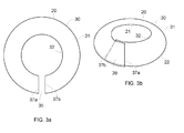
- the frustroconical body is a slit ring as shown in Figures 3a and 3b .
- Figure 3a schematically shows a ring 30 having an outer circumference 31 defining an unobstructed diameter, and an inner circumference 32 defining an inner diameter.
- a cut 35 is provided through the ring 30.
- the cut is shown radially, but this is not required.
- the cut does not need fully cut through the ring as shown, it can for example be a partial slit starting at the outer circumference 31. It is possible to arrange 2,3,4 or more partial slits in the ring.
- the ring is suitably made from a resilient material and has a thickness such that it can be deformed into a frustroconical shape as shown in a perspective view in Figure 3b.
- Figure 3a shows the ends 37a, 37b overlapping. It will be understood that the cut can have a certain width, but preferably the ends still overlap, so that the nappe is closed when viewed along the axis through top and base.
- the deformation shown in Figure 3b is elastic, and therefore the frustroconical member 20 is under radial inward stress and would return to or towards the unobstructed shape of Figure 3a if the radial stress was released.
- the radial stress can be maintained, for example, by a connection in the overlap zone 39. Such fixation is suitably releasable.
- an epoxy resin or solder can be used in a adhesive, such as gluing, connection at surface temperatures, say below 100 °C or below 50 °C, wherein the materials are chosen such that the gluing connection will loosen at elevated temperatures in the well, at 100 °C or above, 150 °C or above, such as at 200 °C or above.
- the temperature in the wellbore will typically not exceed 400 °C.
- An alternative releasable fixation can be arranged in the form of a shear pin, that is selected such that the swelling body contacting the anti-creep device breaks the shear pin, preferably before the body is fully swollen and the seal is formed.
- Figure 2a shows the anti-creep device 15 in a first, radially contracted, configuration.
- the radial inward force is then at least partially released, e.g. by allowing the gluing connection to disintegrate at elevated temperature in the well.
- the frustroconical member 20 thus springs to a second configuration as shown in Figure 2b .
- the base 22 has a second cross-section or diameter larger than the first cross-section or diameter as in Figure 2a , that conforms to the outer circumference or diameter of the space to be sealed.
- the outer wall 10 now exerts a radial inward force compensating a radial outward force exerted by the base 22, seeking to assume its unobstructed diameter that is larger than the diameter of the wall 10.
- Resiliency of the base will conform the base to the cross-section of the wellbore 1, which is still regarded as a substantially frustroconical shape, but it will be understood that there can be deviations from a mathematical ideal shape.
- a length of wellbore can be regarded as a substantially cylindrical shape.
- the wellbore In a cross-section perpendicular to a length direction of the wellbore, the wellbore has typically substantially circular shape.
- substantially circular means that any two measurements of a diameter line dividing the cross-section in two areas of equal size, differ by 25% or less of the larger of the two measurements, in certain cases by 10% or less.
- An ideal frustroconical shape is the shape of a conical frustum, i.e. a frustum created by slicing the top off a cone with the cut made parallel to its base, also referred to as truncated cone.
- the cone can be a generalized cone, which is the surface created by the set of lines passing through a vertex and every point on a boundary. Typically the cone has substantially circular cross-section.
- a substantially frustroconical shape deviates in any dimension (a diameter, a height, a side length), by 25% or less, in certain cases by 10% or less, from a value that would be calculated, assuming a mathematically ideal shape of a generalized cone, and typically also of a cone with circular base, from a measurement of one or more dimensions in selected directions.
- Figure 2b the frustroconical member is expanded against the wellbore wall, before the swellable body has formed a seal.
- Figure 2c shows the situation that the seal is formed.
- the swollen body 8 now presses against the anti-creep device and thereby improves the seal between the base 22 and the wellbore 1. Creep is effectively prevented.
- Figures 2a-2d also show a stop for preventing longitudinal movement of the anti-creep device 15 away from the swellable body 8, in the form of ring 40.
- the ring is provided at the top of the frustroconical member 20, and has a diameter and cross-section larger than the diameter and cross-section of the top in radially contracted ( Fig 2a ) and expanded ( Fig 2b,c ) configuration.
- An advantage of such a ring with a substantially frustroconical member is that also a good seal is formed between the top 21 and the ring 40, so that it is not required to separately seal or connect the top 21 to the tube 5, although it will be understood that this can still be done.
- Figure 2d shows an embodiment in which two anti-creep devices 15 and 15a are provided at the first end 17 and the opposite second end of the swellable body.
- Anti-creep device 15a as shown here is essentially similar to anti-creep device 15, and designated with the same reference numerals with addition of an "a".
- Two or more systems for sealing a space according to the invention can be provided, spaced apart along the tubular. Two such systems can provide a zonal isolation of an annular space in the wellbore.
- the frustroconical member such as from a slit ring, can be made for example from a metal such as galvanized steel, stainless steel, titania, but also of a synthetic material or composite, optionally reinforced.
- a gel-forming material can be used in the system and method of the invention.
- An example of a gel-forming material is a layered silicate that swells and forms a gel in water.
- Suitable layered silicates are sold by Rockwood Additives Limited under the trademark Laponite.
- Suitable gel-forming Laponite grades are e.g. grades RD, XLG, D, DF, XL21, HW, or LV.
- Relevant CAS Nos. of suitable Laponite materials are 53320-86-8 and 64060-48-6.
- Relevant EINECS Nos. of suitable Laponite materials are 258-476-2 and 285-349-9.
- a band or sleeve of gel-forming material containing Laponite can be made by putting Laponite powder in a mould and applying pressure until a solid Laponite band is formed.
- Other components such as e.g. a filler or additives can be added in the moulding process.
- Another suitable gel-forming material when being contacted with water, is or comprises a superabsorbent, such as a polyacrylate and/ or polyacrylamide based superabsobent.
- a superabsorbent such as a polyacrylate and/ or polyacrylamide based superabsobent.
- the polyacrylate and/or polyacrylamide can be cross-linked.
- Suitable superabsorbents are sold by BASF under the trademark Luquasorb.
- Another suitable superabsorbent is sold by Imbibitive Technologies America Inc. (IMBTECH AMERICA) under the trademark AquaBiber.
- Bands or sleeves of gel-forming material can be made from superabsorbants, e.g. Luquasorb or AquaBiber materials, by putting grinded superabsorbent in a mould and applying pressure thereby creating a solid band.
- superabsorbants e.g. Luquasorb or AquaBiber materials
- the metal halides are preferably NaCl or KCl.
- Other components such as e.g. a filler or additives can be added as well.
- Suitable gel-forming material when the selected fluid is or comprises oil, is e.g. an alkylstyrene copolymer, e.g. the material sold under the trademark Imbiber by Imbibitive Technologies America Inc. (IMBTECH AMERICA).
- IMBTECH AMERICA Imbibitive Technologies America Inc.
- the same band forming process as for superabsorbents Luquasorb can for example be used.
- the gel-forming material is suitably not free-flowing, before it is contacted with the selected fluid.
- the gel-forming material can be solid, highly viscous, or thixotropic. Thixotropic materials do not freely flow, but flow when pressure is applied, i.e. show a behaviour like toothpaste.
- the gel-forming material does not contain a substantial quantity of a solvent, e.g. less than 20 wt%, or less than 5 wt%, in particular no solvent.
- a base tubular with an o.d. of 25 mm was equipped with a 250 mm long swellable elastomer sleeve of a fluoroethylene rubber available from Asahi Glass Co., LTD under the tradename AFLAS.
- the layer thickness of the elastomer was 14 mm.
- the base tubular with swellable elastomer was arranged in an outer tube with an i.d. of 60 mm.
- An anti-creep device in the form of a slit ring of a galvanized spring metal (o.d. 70 mm, i.d. 25 mm, thickness 0,45 mm) deformed into frustroconical shape was arranged at one side of the elastomer, as in Figure 2a .
- Creep behaviour leading to plastic deformation can be clearly detected, wherein creep increases with increasing temperature.
Abstract
A system and method for sealing a space in a wellbore formed in an earth formation, the space having a cross-section with an outer circumference, the system comprising a swellable body arranged around a tubular, the swellable body having first and second ends along the tubular, wherein at least one anti-creep device is provided at at least one of the first and second ends, the anti-creep device comprising a substantially frustroconical member having a top, and a base with relatively larger cross-section than the top, the base having an outer circumference that is adjusted or adjustable to the outer circumference of the space to be sealed, and wherein the base is arranged to face the swellable body; and a method of sealing a space in a wellbore formed in an earth formation, the space having a cross-section with an outer circumference; and the method comprising contacting the swellable body with a selected fluid so as to cause swelling until a seal is formed.
Description
- The present invention relates to a system and method for sealing a space in a wellbore formed in an earth formation.
- In the context of production of fluids from a subsurface formation in the earth, such as a reservoir of hydrocarbon fluid, via a wellbore formed in the earth formation it can be desired to provide a seal in the wellbore, such as to prevent transfer of a selected fluid between the subsurface formation and the surface facility. Typically an annular seal around a tubular longitudinally extending in the wellbore is needed. Such an annular seal can be provided by a swellable body that extends around the tubular, e.g. an production tubular installed in the wellbore. The swellable body can in particular be a swellable elastomer body, as known for example from
WO 03/008756 WO 2005/012686 . The swellable body is swellable in a selected fluid, which can for example be aqueous or hydrocarbon based, e.g. water (brine), crude oil, drilling mud. - When the swellable body is contacted with the selected fluid, it swells until it reaches the inner wall of the borehole, thus providing an annular seal. It can happen, however, that the swelling also causes a significant extension or displacement in longitudinal direction, along the tubular and wellbore, respectively. This longitudinal extension or displacement due to swelling is also referred to as creep. Creep behaviour typically increases with temperature. The problem of creep is therefore particularly pronounces in high-temperature wells, at 100 °C or higher, in particular at 150 °C or higher, more in particular at 200 °C or higher. For temperatures up to about 150 C, swellable elastomers based on a polymer matrix of acrylonitrile butadiene rubber (NBR or HNBR) or ethylene propylene dimonomer (EPDM) can be used.
- For higher temperatures, fluorocarbon and/or hydrofluorocarbon elastomers, like the materials available under the tradenames Viton, FKM elastomers, Kalrez, AFLAS, such as tetrafluoroethylene-propylene copolymer, can be used. Such materials, however, show significant creep when exposed to stress at such temperatures.
- The swellable body can also be a gel-forming material, in particular one that is not a rubber.
- Creep is an undesired behaviour for an annular seal, as the seal strength would decrease over time, or the seal can even be broken up.
-
WO 2006/121340 discloses a packer anchoring device for anchoring of an expandable annular packer to a normally tubular object by means of a reinforcement and an expandable end ring for use in a borehole, in order to overcome problems with chemical bonding between an annular packer and a pipe. The expandable end ring has a cross-section in the shape of a right angle, wherein a first leg of the angle forms a disc perpendicular to the pipe it encircles, and the second leg forms a sleeve extending axially. The end ring is slit by a number of first radial slits extending from the inside, and a number of alternate second radial slits extending from the outside. The anchoring device cannot effectively prevent creep, for example because its deliberately weakened structure can fold backwards, away from the swelling packer, when it is expanded. - There is a need for a system for sealing in which creep of a swellable body can be effectively prevented.
- In accordance with the invention there is provided a system for sealing a space in a wellbore formed in an earth formation, the space having a cross-section with an outer circumference, the system comprising a swellable body arranged around a tubular, the swellable body having first and second ends along the tubular, wherein at least one anti-creep device is provided at at least one of the first and second ends, the anti-creep device comprising a substantially frustroconical member having a top, and a base with relatively larger cross-section than the top, the base having an outer circumference that is adjusted or adjustable to the outer circumference of the space to be sealed, and wherein the base is arranged to face the swellable body.
- The invention thus provides an elegant, simple and cost-effective anti-creep device. The substantially frustroconical shape allows the device to conform to the outer circumference of the space to be sealed, such as in an uncased open borehole or a cased borehole, and thus prevents creep. At the same time this shape provides a mechanically strong barrier against pressure from the base side, such as due to the swelling body. Pressure building up against the base side of the frustroconical member can press the base against the outer wall of the space to be sealed, thus further improving the anti-creep property of the device.
- In one embodiment the frustroconical member is, at least at its base, under radial inward stress. This can be the case in a situation that the frustroconical member is run into the wellbore, where the base is radially squeezed to a smaller diameter than the wellbore. Also, the base of the member can be under radial inward stress when it has been adjusted to the wellbore wall. Thus it will exert an outward force against the outer wall of the sealing space, conforming even better to that outer wall. The outer wall can for example be the open hole wall of the wellbore, or the inner wall of a casing. This is a further difference and advantage over the packer-anchoring device known from
WO 2006/121340 , in which the end ring is under radial outward stress and has a tendency to retract from the borehole wall. - In one embodiment the frustroconical member is movable from a first configuration, in which the base has a first cross-section, to a second configuration, in which the base has a second cross-section larger than the first cross-section. In particular, in the second configuration the second cross-section of the base can be determined by an external radial inward force compensating a radial outward force exerted by the base. The second cross-section can be the cross-section of the space to be sealed. An example of a frustroconical member that can assume such first and second configurations is an umbrella-type member, wherein the release from the first configuration can be triggered by a suitable activating mechanism.
- In one embodiment, the frustroconical member is, at least at its base, resilient, the base having an unobstructed cross-section larger than the diameter cross-section of the space to be sealed. This provides improved conforming of the base to the outer wall of the sealing space. The swollen body pushing against the base further improves the conformance.
- In one embodiment the frustroconical member comprises a slit ring under radial inward stress. This is a particularly simple and cost-effective embodiment, which provides a resilient substantially frustroconical member of which the base diameter can be easily adjusted by adjusting radial inward force. The slit ring can have a single cut through the ring, or one or more partial slits starting at the larger diameter of the ring. For example, when a plane ring is cut open at one side, the ends formed by the cut can be slid one over the other, thereby deforming the ring out of the plane to form a substantially frustroconical shape. Preferably, the frustroconical member has a closed nappe when viewed in axial direction. The side wall or hull connecting the top and the base is referred to as nappe. This can be achieved with an inwardly deformed slit ring having an unobstructed outer diameter larger than the maximum diameter of the space to be sealed. The invention thus allows to prevent creep of gel-forming material that is not a rubber. This is a further difference and advantage over the device known from
WO 2006/121340 , in which openings are formed when the packer-anchoring device expands, so that creep can occur. - In one embodiment the system further comprises a stop for preventing longitudinal movement of the anti-creep device away from the swellable body. The stop can be provided at the top of the frustroconical member, preferably having a size or diameter larger than a top diameter of the frustroconical member. The stop can for example be an annular ring around the tubular. The stop can also be a connection to the tubular.
- In one embodiment, the anti-creep device comprises one or more further substantially frustroconical members. For example, several slit rings arranged one behind the other can provide further improved anti-creep properties. The plurality of frustroconical members can be alike, or differ in one or more parameters. Parameters are for example the material from which the members are made, the thickness of the material, the dimensions such as the unobstructed base cross-section or diameter, resilient or elastic properties such as a spring constant.
- In one embodiment the system comprises two anti-creep devices at both the first and second ends. In this way creep at both longitudinal sides of the swellable body can be prevented.
- In one embodiment the swellable body comprises at least one of a swellable elastomer and a gel-forming material. The swellable elastomer, also referred to as swellable rubber, can for example have a polymer matrix made from a polymer selected from the group consisting of acrylonitrile butadiene rubber (e.g. NBR or HNBR), ethylene propylene dimonomer (EPDM), fluorocarbon and/or hydrofluorocarbon elastomers, of which examples are given hereinabove, butyl rubber, silicone rubber. A gel-forming material comprises a gel-forming component selected from the group consisting of a layered silicate, an inorganic polymer, a superabsorbent, and swells and forms a gel when being contacted with a selected fluid, e.g. water and/or hydrocarbon oil.
- The present invention also provides a method of sealing a space in a wellbore formed in an earth formation, the space having a cross-section with an outer circumference, the method comprising - providing in the wellbore a system for sealing the space, the system comprising a swellable body around a tubular, the swellable body having first and second ends along the tubular, and at least one anti-creep device at at least one of the first and second ends, the anti-creep device comprising a substantially frustroconical member having a top, and a base with relatively larger cross-section than the top, wherein the base has an outer circumference that is adjusted to the outer circumference of the space to be sealed, and wherein the base is arranged to face the swellable body - contacting the swellable body with a selected fluid so as to cause swelling until a seal is formed.
- In one embodiment, the frustroconical member is installed in the wellbore in a first configuration, in which the base has a first cross-section, and wherein the frustroconical member is moved to a second configuration, in which the base has a second cross-section larger than the first cross-section that is adjusted to the cross-section of the space to be sealed. In one embodiment the frustroconical member is adjusted to the wellbore wall, i.e. moved to the second configuration, before the swellable body has formed a seal. Installing the anti-creep device adjusted against the wall of the space minimizes the risk of creep during the swelling phase.
- In one embodiment the frustroconical member in the first configuration is, at least at the base, a resilient member under radial inward stress, and wherein it is moved to the second configuration by at least partially releasing the radial inward stress. Such an embodiment of the frustroconical member can for example be easily achieved when using a slit ring. The slit ring can be formed into a frustroconical shape of the first configuration, and for example releasably fixed in that configuration. When it was placed at the desired location in the wellbore, the fixation can be released, so that the base diameter/cross section increases and the base circumference pushes against the outer wall of the sealing space. In one embodiment, releasing the fixation can occur by opening of an adhesive connection under wellbore conditions, e.g. at a prevailing elevated temperature in the wellbore.
- In one embodiment the space in the wellbore is at a temperature of above 100 °C, in particular above 150 °C, more in particular above 200 °C, for at least part of the time that the system for sealing is in the wellbore. This can be during running into the well, or at a later point in time, in unswollen and/or swollen state of the swellable body.
- The method according to the invention can use any one of the systems for sealing according to the present invention.
- The invention will now be further described by way of example and with reference to the drawings, wherein
-
Figures 1a and 1b schematically show a section of an open-hole wellbore provided with a swellable body around a tubular, before and some time after contacting with a selected fluid causing swelling of the swellable body; respectively (not according to the invention); -
Figures 2a through 2d schematically show a section of an open-hole wellbore provided with a swellable body, and at one end or both ends an anti-creep device according to the invention, in various stages; -
Figures 3a and 3b show schematically a slit ring in unobstructed shape, and deformed into a substantially frustroconical shape, respectively. - Like reference numerals are used in the Figures to refer to the same or similar objects.
- Reference is made to
Figure 1a , showing awellbore 1 extending, normally from surface, into the earth and penetrating asubsurface earth formation 3. In the wellbore 1 atubular 5 is provided, which can for example be a production tubular for producing hydrocarbon fluid entering the wellbore at a production zone of the earth formation, and flowing via the production tubular to the surface of the earth. Sometimes it is desired to seal theannular space 6 around the tubular, so as to prevent fluid to flow along the annulus, and/or to provide a pressure separation in theannulus 6. A seal can be obtained by a packer.Figure 1a shows aswellable body 8, such as a swellable elastomer packer, in an unswollen configuration, as it is run into the wellbore.Figure 1b shows theswellable body 8 in a swollen state after some time. It has now extended to theouter wall 10 of the sealing space, but at the same time has extended significantly along the length of thetubular 5. As discussed hereinabove, such creep is particularly pronounced at elevated temperatures, and also for swellable elastomer materials that are designed for use at high temperatures. The creep is typically a deformation that is not reversible. If creep continues, the annular seal can be weakened of even lost. -
Figures 2a through 2d illustrate thesystem 12 and method for sealing according to the present invention. In addition to what has been discussed with reference toFigure 1a , ananti-creep device 15 is provided at afirst end 17 of theswellable body 8. Theanti-creep device 15 comprises a substantiallyfrustroconical member 20 having a top 21 and abase 22. Thebase 22, facing theswellable body 8, has a larger cross-section than the top 21. Cross-section means with respect to the axis of the member, here also extension direction of the wellbore, horizontal in the drawing. The top and base suitably have a substantially circular cross-section, to optimally conform to a substantially circular (substantially cylindrical) wellbore obtained by rotary drilling, or e.g. to a casing in such wellbore. The cross-section and diameter at the top 21 is smaller than the cross-section and diameter at the base. -
Figure 2a shows the swellable elastomer in an unswollen state like inFigure 1a . The anti-creep device is shown in a first configuration, in which the base has a first cross section and diameter, smaller than the cross-section and diameter of sealing space, i.e. the maximum outer diameter ofannular space 6. - In this example the frustroconical body is a slit ring as shown in
Figures 3a and 3b . -
Figure 3a schematically shows aring 30 having anouter circumference 31 defining an unobstructed diameter, and aninner circumference 32 defining an inner diameter. Acut 35 is provided through thering 30. The cut is shown radially, but this is not required. The cut does not need fully cut through the ring as shown, it can for example be a partial slit starting at theouter circumference 31. It is possible to arrange 2,3,4 or more partial slits in the ring. - The ring is suitably made from a resilient material and has a thickness such that it can be deformed into a frustroconical shape as shown in a perspective view in
Figure 3b. Figure 3a shows theends Figure 3b is elastic, and therefore thefrustroconical member 20 is under radial inward stress and would return to or towards the unobstructed shape ofFigure 3a if the radial stress was released. The radial stress can be maintained, for example, by a connection in theoverlap zone 39. Such fixation is suitably releasable. For example, an epoxy resin or solder can be used in a adhesive, such as gluing, connection at surface temperatures, say below 100 °C or below 50 °C, wherein the materials are chosen such that the gluing connection will loosen at elevated temperatures in the well, at 100 °C or above, 150 °C or above, such as at 200 °C or above. The temperature in the wellbore will typically not exceed 400 °C. An alternative releasable fixation can be arranged in the form of a shear pin, that is selected such that the swelling body contacting the anti-creep device breaks the shear pin, preferably before the body is fully swollen and the seal is formed. - Returning to
Figures 2a-2d, Figure 2a shows theanti-creep device 15 in a first, radially contracted, configuration. The radial inward force is then at least partially released, e.g. by allowing the gluing connection to disintegrate at elevated temperature in the well. Thefrustroconical member 20 thus springs to a second configuration as shown inFigure 2b . InFigure 2b thebase 22 has a second cross-section or diameter larger than the first cross-section or diameter as inFigure 2a , that conforms to the outer circumference or diameter of the space to be sealed. In this configuration theouter wall 10 now exerts a radial inward force compensating a radial outward force exerted by thebase 22, seeking to assume its unobstructed diameter that is larger than the diameter of thewall 10. Resiliency of the base will conform the base to the cross-section of thewellbore 1, which is still regarded as a substantially frustroconical shape, but it will be understood that there can be deviations from a mathematical ideal shape. - In particular, it will be understood that a length of wellbore can be regarded as a substantially cylindrical shape. In a cross-section perpendicular to a length direction of the wellbore, the wellbore has typically substantially circular shape. Substantially circular means that any two measurements of a diameter line dividing the cross-section in two areas of equal size, differ by 25% or less of the larger of the two measurements, in certain cases by 10% or less.
- An ideal frustroconical shape is the shape of a conical frustum, i.e. a frustum created by slicing the top off a cone with the cut made parallel to its base, also referred to as truncated cone. The cone can be a generalized cone, which is the surface created by the set of lines passing through a vertex and every point on a boundary. Typically the cone has substantially circular cross-section. Suitably a substantially frustroconical shape deviates in any dimension (a diameter, a height, a side length), by 25% or less, in certain cases by 10% or less, from a value that would be calculated, assuming a mathematically ideal shape of a generalized cone, and typically also of a cone with circular base, from a measurement of one or more dimensions in selected directions.
- In
Figure 2b , the frustroconical member is expanded against the wellbore wall, before the swellable body has formed a seal.Figure 2c shows the situation that the seal is formed. Theswollen body 8 now presses against the anti-creep device and thereby improves the seal between the base 22 and thewellbore 1. Creep is effectively prevented. -
Figures 2a-2d also show a stop for preventing longitudinal movement of theanti-creep device 15 away from theswellable body 8, in the form ofring 40. The ring is provided at the top of thefrustroconical member 20, and has a diameter and cross-section larger than the diameter and cross-section of the top in radially contracted (Fig 2a ) and expanded (Fig 2b,c ) configuration. An advantage of such a ring with a substantially frustroconical member is that also a good seal is formed between the top 21 and thering 40, so that it is not required to separately seal or connect the top 21 to thetube 5, although it will be understood that this can still be done. - It will be understood that several, e.g. 2,3 or 4 frustroconical bodies like 20 can be arranged one behind the other along the
tubular 5. -
Figure 2d shows an embodiment in which twoanti-creep devices first end 17 and the opposite second end of the swellable body.Anti-creep device 15a as shown here is essentially similar toanti-creep device 15, and designated with the same reference numerals with addition of an "a". - Two or more systems for sealing a space according to the invention can be provided, spaced apart along the tubular. Two such systems can provide a zonal isolation of an annular space in the wellbore.
- The frustroconical member, such as from a slit ring, can be made for example from a metal such as galvanized steel, stainless steel, titania, but also of a synthetic material or composite, optionally reinforced.
- Instead of a swellable elastomer, a gel-forming material can be used in the system and method of the invention. An example of a gel-forming material is a layered silicate that swells and forms a gel in water. Suitable layered silicates are sold by Rockwood Additives Limited under the trademark Laponite. Suitable gel-forming Laponite grades are e.g. grades RD, XLG, D, DF, XL21, HW, or LV. Relevant CAS Nos. of suitable Laponite materials are 53320-86-8 and 64060-48-6. Relevant EINECS Nos. of suitable Laponite materials are 258-476-2 and 285-349-9.
- For example, a band or sleeve of gel-forming material containing Laponite can be made by putting Laponite powder in a mould and applying pressure until a solid Laponite band is formed. Other components such as e.g. a filler or additives can be added in the moulding process.
- Another suitable gel-forming material, when being contacted with water, is or comprises a superabsorbent, such as a polyacrylate and/ or polyacrylamide based superabsobent. The polyacrylate and/or polyacrylamide can be cross-linked. Suitable superabsorbents are sold by BASF under the trademark Luquasorb. Another suitable superabsorbent is sold by Imbibitive Technologies America Inc. (IMBTECH AMERICA) under the trademark AquaBiber.
- Bands or sleeves of gel-forming material can be made from superabsorbants, e.g. Luquasorb or AquaBiber materials, by putting grinded superabsorbent in a mould and applying pressure thereby creating a solid band. Depending on the salinity of the surrounding formation or completion fluids between 1-50 w/w% of metal halides, based on the mass of superabsorbent, can be added. The metal halides are preferably NaCl or KCl. Other components such as e.g. a filler or additives can be added as well.
- Suitable gel-forming material, when the selected fluid is or comprises oil, is e.g. an alkylstyrene copolymer, e.g. the material sold under the trademark Imbiber by Imbibitive Technologies America Inc. (IMBTECH AMERICA). The same band forming process as for superabsorbents Luquasorb can for example be used.
- The gel-forming material is suitably not free-flowing, before it is contacted with the selected fluid. For example, the gel-forming material can be solid, highly viscous, or thixotropic. Thixotropic materials do not freely flow, but flow when pressure is applied, i.e. show a behaviour like toothpaste. The gel-forming material does not contain a substantial quantity of a solvent, e.g. less than 20 wt%, or less than 5 wt%, in particular no solvent.
- A base tubular with an o.d. of 25 mm was equipped with a 250 mm long swellable elastomer sleeve of a fluoroethylene rubber available from Asahi Glass Co., LTD under the tradename AFLAS. The layer thickness of the elastomer was 14 mm. The base tubular with swellable elastomer was arranged in an outer tube with an i.d. of 60 mm. An anti-creep device in the form of a slit ring of a galvanized spring metal (o.d. 70 mm, i.d. 25 mm, thickness 0,45 mm) deformed into frustroconical shape was arranged at one side of the elastomer, as in
Figure 2a . The ends of the slit ring were glued together with an epoxy resin. The whole arrangement was put at 100 bar pressure and water was pumped around the packer element at 5 ml/min. The whole arrangement was subsequently heated to 275 °C. At about 100°C the epoxy glue connection opened, and the anti-creep device took the form ofFigure 2b . After 24 hours the swellable packer element was sealing against the outer tube and a constant differential pressure of 20 bars was maintained, with the low-pressure side at the side of the anti-creep-device. By swelling the hollow space in the frustroconical shape of the anti-creep device filled up. During an extended period of 40 days at 275 °C and 20 bars differential pressure no mechanical deformation at the anti-creep device was noticed; there was no creep around the edges of the device, and the devices stayed at its place. - The same elastomer was tested in dynamic mechanical analysis test, at a pressure of 6 bar (0.6 MPa). The results are shown in Table 1
Table 1 Temperature (°C) Creep (cm/day) 100 1.62E-04 200 1.71E-03 275 2.79E-03 - Creep behaviour leading to plastic deformation can be clearly detected, wherein creep increases with increasing temperature.
Claims (15)
- A system for sealing a space in a wellbore formed in an earth formation, the space having a cross-section with an outer circumference, the system comprising a swellable body arranged around a tubular, the swellable body having first and second ends along the tubular, wherein at least one anti-creep device is provided at at least one of the first and second ends, the anti-creep device comprising a substantially frustroconical member having a top, and a base with relatively larger cross-section than the top, the base having an outer circumference that is adjusted or adjustable to the outer circumference of the space to be sealed, and wherein the base is arranged to face the swellable body.
- The system according to claim 1, wherein the frustroconical member at least at its base is under radial inward stress.
- The system according to claim 1 or 2, wherein the frustroconical member is movable from a first configuration, in which the base has a first cross-section, to a second configuration, in which the base has a second cross-section larger than the first cross-section.
- The system according to claim 3, and wherein in the second configuration the second cross-section of the base is determined by an external radial inward force compensating a radial outward force exerted by the base.
- The system according to any one of claims 1-4, wherein the frustroconical member is, at least at its base, resilient, the base having an unobstructed cross-section larger than the cross-section of the space to be sealed.
- The system according to any one of claims 1-5, wherein the frustroconical member comprises a slit ring under radial inward stress.
- The system according to any one of claims 1-6, wherein the system further comprises a stop for preventing longitudinal movement of the anti-creep device away from the swellable body.
- The system according to any one of claims 1-7, wherein the anti-creep device comprises one or more further substantially frustroconical bodies.
- The system according to any one of claims 1-8, wherein the system comprises two anti-creep devices at both the first and second ends.
- The system according to any one of claims 1-9, wherein the swellable body comprises at least one of a swellable elastomer, and a gel-forming material.
- A method of sealing a space in a wellbore formed in an earth formation, the space having a cross-section with an outer circumference, the method comprising- providing in the wellbore a system for sealing the space, the system comprising a swellable body around a tubular, the swellable body having first and second ends along the tubular, and at least one anti-creep device at at least one of the first and second ends, the anti-creep device comprising a substantially frustroconical member having a top, and a base with relatively larger cross-section than the top, wherein the base
has an outer circumference that is adjusted to the outer circumference of the space to be sealed, and wherein the base is arranged to face the swellable body- contacting the swellable body with a selected fluid so as to cause swelling until a seal is formed. - The method according to claim 11, wherein the frustroconical member is installed in the wellbore in a first configuration, in which the base has a first cross-section, and wherein the frustroconical member is moved to a second configuration, in which the base has a second cross-section larger than the first cross-section that is adjusted to the cross-section of the space to be sealed.
- The method according to claim 11 or 12, wherein the frustroconical member in the first configuration is a resilient body under radial inward stress, and wherein it is moved to the second configuration by at least partially releasing the radial inward stress.
- The method according to any one of claims 11-13, wherein the space in the wellbore is at a temperature of above 100 °C, in particular above 150 °C, more in particular above 200 °C, for at least part of the time that the system for sealing is in the wellbore.
- The method according to any one of claims 11-14, wherein the frustroconical member comprises a slit ring under radial inward stress.
Priority Applications (2)
| Application Number | Priority Date | Filing Date | Title |
|---|---|---|---|
| EP10196480A EP2469016A1 (en) | 2010-12-22 | 2010-12-22 | System and method for sealing a space in a wellbore |
| PCT/EP2011/073326 WO2012084887A1 (en) | 2010-12-22 | 2011-12-20 | System and method for sealing a space in a wellbore |
Applications Claiming Priority (1)
| Application Number | Priority Date | Filing Date | Title |
|---|---|---|---|
| EP10196480A EP2469016A1 (en) | 2010-12-22 | 2010-12-22 | System and method for sealing a space in a wellbore |
Publications (1)
| Publication Number | Publication Date |
|---|---|
| EP2469016A1 true EP2469016A1 (en) | 2012-06-27 |
Family
ID=43899594
Family Applications (1)
| Application Number | Title | Priority Date | Filing Date |
|---|---|---|---|
| EP10196480A Withdrawn EP2469016A1 (en) | 2010-12-22 | 2010-12-22 | System and method for sealing a space in a wellbore |
Country Status (2)
| Country | Link |
|---|---|
| EP (1) | EP2469016A1 (en) |
| WO (1) | WO2012084887A1 (en) |
Cited By (1)
| Publication number | Priority date | Publication date | Assignee | Title |
|---|---|---|---|---|
| RU2525888C1 (en) * | 2013-06-06 | 2014-08-20 | Федеральное государственное бюджетное образовательное учреждение высшего профессионального образования "Уфимский государственный нефтяной технический университет" | Downhole rotary pump filter |
Citations (11)
| Publication number | Priority date | Publication date | Assignee | Title |
|---|---|---|---|---|
| WO2003008756A1 (en) | 2001-07-18 | 2003-01-30 | Shell Internationale Research Maatschappij B.V. | Wellbore system with annular seal member |
| US20040055758A1 (en) * | 2002-09-23 | 2004-03-25 | Brezinski Michael M. | Annular isolators for expandable tubulars in wellbores |
| WO2005012686A1 (en) | 2003-07-29 | 2005-02-10 | Shell Internationale Research Maatschappij B.V. | System for sealing a space in a wellbore |
| WO2006121340A1 (en) | 2005-05-09 | 2006-11-16 | Halliburton Energy Services, Inc. | Packer-anchoring device |
| US20070027245A1 (en) * | 2005-07-18 | 2007-02-01 | Schlumberger Technology Corporation | Swellable Elastomer-Based Apparatus, Oilfield Elements Comprising Same, and Methods of Using Same in Oilfield Applications |
| WO2008062186A1 (en) * | 2006-11-21 | 2008-05-29 | Swelltec Limited | Downhole apparatus and support structure therefor |
| WO2008154392A1 (en) * | 2007-06-06 | 2008-12-18 | Baker Hughes Incorporated | Swellable packer with back-up systems |
| EP2096256A1 (en) * | 2008-02-27 | 2009-09-02 | Swelltec Limited | Method of forming a downhole apparatus |
| WO2010019819A1 (en) * | 2008-08-15 | 2010-02-18 | Schlumberger Canada Limited | Anti-extrusion device for swell rubber packer |
| EP2246522A2 (en) * | 2009-05-01 | 2010-11-03 | Swelltec Limited | Improvements to Swellable Apparatus |
| US20100288486A1 (en) * | 2009-05-15 | 2010-11-18 | Andrew Kutac | Swellable Downhole Packer |
-
2010
- 2010-12-22 EP EP10196480A patent/EP2469016A1/en not_active Withdrawn
-
2011
- 2011-12-20 WO PCT/EP2011/073326 patent/WO2012084887A1/en active Application Filing
Patent Citations (11)
| Publication number | Priority date | Publication date | Assignee | Title |
|---|---|---|---|---|
| WO2003008756A1 (en) | 2001-07-18 | 2003-01-30 | Shell Internationale Research Maatschappij B.V. | Wellbore system with annular seal member |
| US20040055758A1 (en) * | 2002-09-23 | 2004-03-25 | Brezinski Michael M. | Annular isolators for expandable tubulars in wellbores |
| WO2005012686A1 (en) | 2003-07-29 | 2005-02-10 | Shell Internationale Research Maatschappij B.V. | System for sealing a space in a wellbore |
| WO2006121340A1 (en) | 2005-05-09 | 2006-11-16 | Halliburton Energy Services, Inc. | Packer-anchoring device |
| US20070027245A1 (en) * | 2005-07-18 | 2007-02-01 | Schlumberger Technology Corporation | Swellable Elastomer-Based Apparatus, Oilfield Elements Comprising Same, and Methods of Using Same in Oilfield Applications |
| WO2008062186A1 (en) * | 2006-11-21 | 2008-05-29 | Swelltec Limited | Downhole apparatus and support structure therefor |
| WO2008154392A1 (en) * | 2007-06-06 | 2008-12-18 | Baker Hughes Incorporated | Swellable packer with back-up systems |
| EP2096256A1 (en) * | 2008-02-27 | 2009-09-02 | Swelltec Limited | Method of forming a downhole apparatus |
| WO2010019819A1 (en) * | 2008-08-15 | 2010-02-18 | Schlumberger Canada Limited | Anti-extrusion device for swell rubber packer |
| EP2246522A2 (en) * | 2009-05-01 | 2010-11-03 | Swelltec Limited | Improvements to Swellable Apparatus |
| US20100288486A1 (en) * | 2009-05-15 | 2010-11-18 | Andrew Kutac | Swellable Downhole Packer |
Cited By (1)
| Publication number | Priority date | Publication date | Assignee | Title |
|---|---|---|---|---|
| RU2525888C1 (en) * | 2013-06-06 | 2014-08-20 | Федеральное государственное бюджетное образовательное учреждение высшего профессионального образования "Уфимский государственный нефтяной технический университет" | Downhole rotary pump filter |
Also Published As
| Publication number | Publication date |
|---|---|
| WO2012084887A1 (en) | 2012-06-28 |
Similar Documents
| Publication | Publication Date | Title |
|---|---|---|
| US8997854B2 (en) | Swellable packer anchors | |
| EP1339944B1 (en) | High temperature and pressure packer | |
| US7963321B2 (en) | Swellable downhole packer | |
| US20160194933A1 (en) | Improved Isolation Barrier | |
| WO2014089150A1 (en) | Fold back swell packer | |
| US8607883B2 (en) | Swellable packer having thermal compensation | |
| CN107002476B (en) | Temperature activated zone separation packer apparatus | |
| WO2016163986A1 (en) | Compliant slip assembly for securing well tools in a tubing string | |
| NO20170317A1 (en) | Internally trussed high-expansion support for inflow control device sealing applications | |
| NO20180297A1 (en) | Packing element having a bonded petal anti-extrusion device | |
| US8800649B2 (en) | Shape memory cement annulus gas migration prevention apparatus | |
| EP2469016A1 (en) | System and method for sealing a space in a wellbore | |
| EP2469017A1 (en) | System and method for providing a pressure seal | |
| US20150211323A1 (en) | Sealing apparatus and method | |
| WO2014092714A1 (en) | Swellable packer construction | |
| EP2847420B1 (en) | Swellable packer having reinforcement plate | |
| US20150204160A1 (en) | Isolation Barrier | |
| GB2504319A (en) | Annular seal back up assembly |
Legal Events
| Date | Code | Title | Description |
|---|---|---|---|
| AK | Designated contracting states |
Kind code of ref document: A1 Designated state(s): AL AT BE BG CH CY CZ DE DK EE ES FI FR GB GR HR HU IE IS IT LI LT LU LV MC MK MT NL NO PL PT RO RS SE SI SK SM TR |
|
| AX | Request for extension of the european patent |
Extension state: BA ME |
|
| PUAI | Public reference made under article 153(3) epc to a published international application that has entered the european phase |
Free format text: ORIGINAL CODE: 0009012 |
|
| STAA | Information on the status of an ep patent application or granted ep patent |
Free format text: STATUS: THE APPLICATION IS DEEMED TO BE WITHDRAWN |
|
| 18D | Application deemed to be withdrawn |
Effective date: 20130103 |