EP2468596B1 - A method of monitoring aircraft brake performance and apparatus for performing such a method - Google Patents
A method of monitoring aircraft brake performance and apparatus for performing such a method Download PDFInfo
- Publication number
- EP2468596B1 EP2468596B1 EP11193500.3A EP11193500A EP2468596B1 EP 2468596 B1 EP2468596 B1 EP 2468596B1 EP 11193500 A EP11193500 A EP 11193500A EP 2468596 B1 EP2468596 B1 EP 2468596B1
- Authority
- EP
- European Patent Office
- Prior art keywords
- brake
- energy
- performance
- demand
- absorbed
- Prior art date
- Legal status (The legal status is an assumption and is not a legal conclusion. Google has not performed a legal analysis and makes no representation as to the accuracy of the status listed.)
- Not-in-force
Links
Images


Classifications
-
- B—PERFORMING OPERATIONS; TRANSPORTING
- B60—VEHICLES IN GENERAL
- B60T—VEHICLE BRAKE CONTROL SYSTEMS OR PARTS THEREOF; BRAKE CONTROL SYSTEMS OR PARTS THEREOF, IN GENERAL; ARRANGEMENT OF BRAKING ELEMENTS ON VEHICLES IN GENERAL; PORTABLE DEVICES FOR PREVENTING UNWANTED MOVEMENT OF VEHICLES; VEHICLE MODIFICATIONS TO FACILITATE COOLING OF BRAKES
- B60T17/00—Component parts, details, or accessories of power brake systems not covered by groups B60T8/00, B60T13/00 or B60T15/00, or presenting other characteristic features
- B60T17/18—Safety devices; Monitoring
- B60T17/22—Devices for monitoring or checking brake systems; Signal devices
-
- B—PERFORMING OPERATIONS; TRANSPORTING
- B60—VEHICLES IN GENERAL
- B60T—VEHICLE BRAKE CONTROL SYSTEMS OR PARTS THEREOF; BRAKE CONTROL SYSTEMS OR PARTS THEREOF, IN GENERAL; ARRANGEMENT OF BRAKING ELEMENTS ON VEHICLES IN GENERAL; PORTABLE DEVICES FOR PREVENTING UNWANTED MOVEMENT OF VEHICLES; VEHICLE MODIFICATIONS TO FACILITATE COOLING OF BRAKES
- B60T8/00—Arrangements for adjusting wheel-braking force to meet varying vehicular or ground-surface conditions, e.g. limiting or varying distribution of braking force
- B60T8/17—Using electrical or electronic regulation means to control braking
- B60T8/1701—Braking or traction control means specially adapted for particular types of vehicles
- B60T8/1703—Braking or traction control means specially adapted for particular types of vehicles for aircrafts
-
- B—PERFORMING OPERATIONS; TRANSPORTING
- B64—AIRCRAFT; AVIATION; COSMONAUTICS
- B64D—EQUIPMENT FOR FITTING IN OR TO AIRCRAFT; FLIGHT SUITS; PARACHUTES; ARRANGEMENT OR MOUNTING OF POWER PLANTS OR PROPULSION TRANSMISSIONS IN AIRCRAFT
- B64D45/00—Aircraft indicators or protectors not otherwise provided for
-
- F—MECHANICAL ENGINEERING; LIGHTING; HEATING; WEAPONS; BLASTING
- F01—MACHINES OR ENGINES IN GENERAL; ENGINE PLANTS IN GENERAL; STEAM ENGINES
- F01D—NON-POSITIVE DISPLACEMENT MACHINES OR ENGINES, e.g. STEAM TURBINES
- F01D5/00—Blades; Blade-carrying members; Heating, heat-insulating, cooling or antivibration means on the blades or the members
- F01D5/02—Blade-carrying members, e.g. rotors
- F01D5/021—Blade-carrying members, e.g. rotors for flow machines or engines with only one axial stage
-
- F—MECHANICAL ENGINEERING; LIGHTING; HEATING; WEAPONS; BLASTING
- F01—MACHINES OR ENGINES IN GENERAL; ENGINE PLANTS IN GENERAL; STEAM ENGINES
- F01D—NON-POSITIVE DISPLACEMENT MACHINES OR ENGINES, e.g. STEAM TURBINES
- F01D5/00—Blades; Blade-carrying members; Heating, heat-insulating, cooling or antivibration means on the blades or the members
- F01D5/02—Blade-carrying members, e.g. rotors
- F01D5/022—Blade-carrying members, e.g. rotors with concentric rows of axial blades
-
- F—MECHANICAL ENGINEERING; LIGHTING; HEATING; WEAPONS; BLASTING
- F01—MACHINES OR ENGINES IN GENERAL; ENGINE PLANTS IN GENERAL; STEAM ENGINES
- F01D—NON-POSITIVE DISPLACEMENT MACHINES OR ENGINES, e.g. STEAM TURBINES
- F01D5/00—Blades; Blade-carrying members; Heating, heat-insulating, cooling or antivibration means on the blades or the members
- F01D5/02—Blade-carrying members, e.g. rotors
- F01D5/025—Fixing blade carrying members on shafts
-
- F—MECHANICAL ENGINEERING; LIGHTING; HEATING; WEAPONS; BLASTING
- F01—MACHINES OR ENGINES IN GENERAL; ENGINE PLANTS IN GENERAL; STEAM ENGINES
- F01D—NON-POSITIVE DISPLACEMENT MACHINES OR ENGINES, e.g. STEAM TURBINES
- F01D5/00—Blades; Blade-carrying members; Heating, heat-insulating, cooling or antivibration means on the blades or the members
- F01D5/02—Blade-carrying members, e.g. rotors
- F01D5/08—Heating, heat-insulating or cooling means
-
- F—MECHANICAL ENGINEERING; LIGHTING; HEATING; WEAPONS; BLASTING
- F02—COMBUSTION ENGINES; HOT-GAS OR COMBUSTION-PRODUCT ENGINE PLANTS
- F02C—GAS-TURBINE PLANTS; AIR INTAKES FOR JET-PROPULSION PLANTS; CONTROLLING FUEL SUPPLY IN AIR-BREATHING JET-PROPULSION PLANTS
- F02C3/00—Gas-turbine plants characterised by the use of combustion products as the working fluid
- F02C3/04—Gas-turbine plants characterised by the use of combustion products as the working fluid having a turbine driving a compressor
- F02C3/06—Gas-turbine plants characterised by the use of combustion products as the working fluid having a turbine driving a compressor the compressor comprising only axial stages
- F02C3/073—Gas-turbine plants characterised by the use of combustion products as the working fluid having a turbine driving a compressor the compressor comprising only axial stages the compressor and turbine stages being concentric
-
- B—PERFORMING OPERATIONS; TRANSPORTING
- B64—AIRCRAFT; AVIATION; COSMONAUTICS
- B64C—AEROPLANES; HELICOPTERS
- B64C25/00—Alighting gear
- B64C25/32—Alighting gear characterised by elements which contact the ground or similar surface
- B64C25/42—Arrangement or adaptation of brakes
-
- B—PERFORMING OPERATIONS; TRANSPORTING
- B64—AIRCRAFT; AVIATION; COSMONAUTICS
- B64D—EQUIPMENT FOR FITTING IN OR TO AIRCRAFT; FLIGHT SUITS; PARACHUTES; ARRANGEMENT OR MOUNTING OF POWER PLANTS OR PROPULSION TRANSMISSIONS IN AIRCRAFT
- B64D45/00—Aircraft indicators or protectors not otherwise provided for
- B64D2045/0085—Devices for aircraft health monitoring, e.g. monitoring flutter or vibration
-
- Y—GENERAL TAGGING OF NEW TECHNOLOGICAL DEVELOPMENTS; GENERAL TAGGING OF CROSS-SECTIONAL TECHNOLOGIES SPANNING OVER SEVERAL SECTIONS OF THE IPC; TECHNICAL SUBJECTS COVERED BY FORMER USPC CROSS-REFERENCE ART COLLECTIONS [XRACs] AND DIGESTS
- Y02—TECHNOLOGIES OR APPLICATIONS FOR MITIGATION OR ADAPTATION AGAINST CLIMATE CHANGE
- Y02T—CLIMATE CHANGE MITIGATION TECHNOLOGIES RELATED TO TRANSPORTATION
- Y02T50/00—Aeronautics or air transport
- Y02T50/60—Efficient propulsion technologies, e.g. for aircraft
Definitions
- the present invention is concerned with a method of monitoring vehicle wheel brake performance, and an apparatus for performing such a method. More specifically, the present invention is concerned with a method of monitoring aircraft landing gear brake performance, and an apparatus for performing such a method.
- a significant proportion of aircraft braking is performed by the wheel brakes (in addition to airbrakes and thrust reversers). Braking events during taxiing and landing require a significant amount of kinetic energy of the aircraft to be dissipated. This kinetic energy is converted into thermal and acoustic energy by friction within the brake system.
- the performance of aircraft brakes is monitored and reported by the aircraft flight crew and ground crew. For example, the flight crew are aware if certified stopping distances are not met. Abnormal brake temperature detected by onboard sensors may be indicative of brake performance problems. Asymmetric braking is also indicative of a performance problem with one of the braking systems. Regular visual inspections of the brake systems are also carried out by ground crew to look for visual indicators (e.g. uneven or excessive wear).
- US 6 739 675 B1 discloses a brake effort monitor software logic program for a transit vehicle such as a railcar. A performance comparison signal is generated by dividing an actual energy sum signal by a requested energy sum signal.
- US 4 822 113 A discloses a system for controlling the torque developed by a fluid actuated brake.
- the above method provides a metric which can be compared to an ideal, or performing brake system. If the brake performance indicator falls outside the expected, or ideal, range, then the brake can be scheduled for service at the next appropriate occasion.
- the brake performance input variable is brake demand.
- the brake performance input variable is brake servo pressure.
- Brake servo pressure is then converted to an estimated brake torque demand.
- the estimated brake torque demand may be a percent (%) brake torque demand.
- the method comprises the steps of:
- the step of calculating the energy demand comprises the steps of:
- the use of the wheel speed in the calculation helps to eliminate events such as wheel slip or skid from affecting the calculation.
- the brake performance output variable is brake torque.
- brake torque is measured at the brake.
- the method comprises the steps of:
- the method comprises the steps of:
- the brake performance criterion is at least three standard deviations of a normal distribution of brake energy differentials from a relationship between energy demand and energy absorbed for a healthy brake.
- an alert is produced if impaired performance of the brake is detected.
- an aircraft wheel brake monitoring apparatus according to claim 13.
- an aircraft braking system 100 comprising a mechanical input 102.
- This is, for example, a brake pedal operated by the pilot.
- the input 102 is connected to a hydraulic master cylinder 104 via a servomechanism (not shown) comprising a piston 106 arranged to pressurise a working chamber 108.
- the working chamber 108 is in fluid communication with a brake line 110 which in turn is connected to a slave cylinder of a brake caliper 112 which is arranged to slow a wheel 114 of a landing gear 116 in order to decelerate the aircraft.
- the present invention is based on the ability to compare an energy demand (from the pilot) to the actual energy used by the brakes during a braking operation.
- this can be estimated (“pseudo" energy demand) using the input variable of torque demand applied by the pilot.
- this torque demand is not directly measured but instead is estimated from the brake servo pressure in chamber 108.
- a pressure transducer in the chamber 108 measures brake servo pressure.
- a plot of servo pressure over time can be seen in Figure 4 .
- a variation in brake servo pressure over time can be seen with time plotted on the x-axis 126 and servo pressure on the y-axis 128. It will be noted, for example, that a skid event 130 can be observed in which servo pressure drops.
- the x-axis 118 represents pilot brake pedal demand ranging from 0 to 100 percent.
- the y-axis 120 represents the servo pressure created in the working chamber 108 as a result.
- the x-axis 122 represents time and the y-axis 124 represents braking torque.
- the wheel speed is required.
- a typical landing gear comprises a speed sensor and, referring to Figure 5 , a variation in wheel speed is shown over time with time, plotted on the x-axis 132, and wheel speed on the y-axis 134. It will be noted that the skid event 130 is also visible on this graph.
- step 200 the start of a braking event is detected by an appropriate sensor (this may be the servo pressure transducer and/or the brake torque sensor).
- step 202 appropriate data files are created in the memory of an onboard computer.
- steps 204, 206 and 210 brake servo pressure, torque and speed at the wheel respectively are recorded during the braking event.
- brake servo pressure is converted to estimated torque demand as described above (i.e. by applying the linear pressure - torque demand model).
- step 214 the estimated torque demand 208 is multiplied by the wheel speed 210 to provide the power demand characteristic.
- step 216 the torque at the wheel 206 is multiplied by the wheel speed 210 to provide the actual power characteristic.
- the power characteristics are integrated over the braking event to produce a total estimated energy demand 220 and total energy absorbed 222 respectively.
- step 224 these two values are compared in order to produce a performance metric in the form of an energy differential 226.
- the energy differential is the amount by which the actual energy absorbed differs from an expected energy absorbed given the pseudo energy demand.
- the energy differential is compared to a statistical model (as will be described below) in order to determine brake performance. If brake performance is outside the expected range then an alert is produced at step 230. Otherwise, the system returns to a dormant state until the next braking operation.
- the brake performance metric is the difference between an expected energy absorbed and the actual energy absorbed at the brake (i.e. an energy differential).
- pseudo-energy demand is plotted on x-axis 136 versus actual energy absorbed on y-axis 138 for a multitude of braking events for healthy brakes. As can be seen, there is an approximate linear relationship 140 between these two figures. Any deviation from this ideal relationship is indicative of detrimental performance of the brake.
- a histogram of brake energy differential (i.e. the difference between the actual energy absorbed and the ideal relationship 140) is plotted on the x-axis 142 with frequency on the y-axis 144. As can be seen, this follows a normal distribution having a mean of 0 and a standard deviation s.
- FIG. 9 this plot is identical to that of Figure 8 , but with a linear plot of three standard deviations 146 and four standard deviations 148 below the line 140. As can be seen, it is rare for the actual energy absorbed to drop three standard deviations below the expected value for a healthy brake (represented by line 140) and even rarer to drop four standard deviations below the line 140. The probability of the differential being over three standard deviations is 1 in 373, and over four standard deviations is 1 in 15787. As such, these values represent a suitable indicator of when a brake is malfunctioning.
- the system can be modified to produce an alert should the brake pressure differential fall outside three standard deviations more than once in a given number of braking events, thus indicating a repetitive problem with the brake. This would also eliminate false alerts from statistical anomalies.
Landscapes
- Engineering & Computer Science (AREA)
- Mechanical Engineering (AREA)
- General Engineering & Computer Science (AREA)
- Transportation (AREA)
- Aviation & Aerospace Engineering (AREA)
- Chemical & Material Sciences (AREA)
- Combustion & Propulsion (AREA)
- Regulating Braking Force (AREA)
- Valves And Accessory Devices For Braking Systems (AREA)
Description
- The present invention is concerned with a method of monitoring vehicle wheel brake performance, and an apparatus for performing such a method. More specifically, the present invention is concerned with a method of monitoring aircraft landing gear brake performance, and an apparatus for performing such a method.
- A significant proportion of aircraft braking is performed by the wheel brakes (in addition to airbrakes and thrust reversers). Braking events during taxiing and landing require a significant amount of kinetic energy of the aircraft to be dissipated. This kinetic energy is converted into thermal and acoustic energy by friction within the brake system.
- At present, the performance of aircraft brakes is monitored and reported by the aircraft flight crew and ground crew. For example, the flight crew are aware if certified stopping distances are not met. Abnormal brake temperature detected by onboard sensors may be indicative of brake performance problems. Asymmetric braking is also indicative of a performance problem with one of the braking systems. Regular visual inspections of the brake systems are also carried out by ground crew to look for visual indicators (e.g. uneven or excessive wear).
US 6 739 675 B1 , discloses a brake effort monitor software logic program for a transit vehicle such as a railcar. A performance comparison signal is generated by dividing an actual energy sum signal by a requested energy sum signal.US 4 822 113 A discloses a system for controlling the torque developed by a fluid actuated brake. - It will be noted that significant redundancy is built into aircraft braking systems such that a poorly performing brake is accounted for by other brakes on the aircraft. Such redundancy ensures that detrimental brake performance does not affect the ability of the aircraft to come to a full and complete stop. Nevertheless, proper monitoring of brake performance degradation before the above mentioned effects become noticeable would be beneficial so that inspection and service can be scheduled into the aircraft's flight plan. Expensive, inconvenient and unexpected delays due to servicing can thereby be avoided.
- It is an object of the present invention to provide an aircraft wheel brake monitoring method and apparatus which mitigates the above mentioned problems.
- According to a first aspect of the invention there is provided a method of monitoring the performance of an aircraft wheel brake according to claim 1.
- Advantageously, the above method provides a metric which can be compared to an ideal, or performing brake system. If the brake performance indicator falls outside the expected, or ideal, range, then the brake can be scheduled for service at the next appropriate occasion.
- Preferably the brake performance input variable is brake demand.
- Preferably the brake performance input variable is brake servo pressure. Brake servo pressure is then converted to an estimated brake torque demand.
- The estimated brake torque demand may be a percent (%) brake torque demand.
- Preferably the method comprises the steps of:
- providing a braked wheel arranged to be braked by the brake,
- recording the speed of the braked wheel during the braking operation,
- using the braked wheel speed to calculate the energy demand.
- Preferably the step of calculating the energy demand comprises the steps of:
- multiplying the estimated brake torque demand by the speed of the braked wheel to calculate power demand data,
- integrating the power demand data over time to calculate the energy demand.
- The use of the wheel speed in the calculation helps to eliminate events such as wheel slip or skid from affecting the calculation.
- Preferably the brake performance output variable is brake torque.
- Preferably brake torque is measured at the brake.
- Preferably the method comprises the steps of:
- providing a braked wheel arranged to be braked by the brake,
- monitoring the speed of the braked wheel during the braking operation,
- using the braked wheel speed to calculate the energy absorbed.
- Preferably the method comprises the steps of:
- multiplying the brake torque by the speed of the braked wheel to calculate power absorbed data,
- integrating the power absorbed data over time to calculate the energy absorbed.
- According to the invention, the brake performance criterion is at least three standard deviations of a normal distribution of brake energy differentials from a relationship between energy demand and energy absorbed for a healthy brake.
- Preferably an alert is produced if impaired performance of the brake is detected.
- According to a second aspect of the invention there is provided an aircraft wheel brake monitoring apparatus according to claim 13.
- By using the brake speed in the energy demand calculation, erroneous results due to wheel lock / skidding can be avoided, which would otherwise cause a large difference in energy demand and actual energy absorbed.
- An example method and apparatus, in accordance with the present invention, will now be described with reference to the following Figures:
-
FIGURE 1 is a simplified schematic view of an aircraft landing gear braking system; -
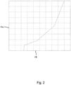
FIGURE 2 is an example plot of brake pedal demand versus brake servo pressure; -
FIGURE 3 is a plot of the brake torque over time during a braking operation; -
FIGURE 4 is a plot of brake servo pressure over time during the braking operation ofFigure 3 ; -
FIGURE 5 is a plot of wheel speed over time during the braking operation ofFigure 3 ; -
FIGURE 6 is a flow chart of a method in accordance with the present invention; -
FIGURE 7 is a plot of pseudo energy demand versus energy absorbed for a plurality of braking operations; -
FIGURE 8 is a histogram of energy residuals for the plot ofFigure 7 ; and -
FIGURE 9 is a plot similar to that ofFigure 7 with multiples of the standard deviation of the statistical model ofFigure 8 plotted thereon. - Turning to
Figure 1 there is provided anaircraft braking system 100 comprising amechanical input 102. This is, for example, a brake pedal operated by the pilot. Theinput 102 is connected to ahydraulic master cylinder 104 via a servomechanism (not shown) comprising apiston 106 arranged to pressurise a workingchamber 108. The workingchamber 108 is in fluid communication with abrake line 110 which in turn is connected to a slave cylinder of abrake caliper 112 which is arranged to slow awheel 114 of alanding gear 116 in order to decelerate the aircraft. - The present invention is based on the ability to compare an energy demand (from the pilot) to the actual energy used by the brakes during a braking operation.
- Because energy is not directly measurable, appropriate input and output variables need to be measured and used to estimate the energy demand and usage at the brake.
- In terms of energy demand, this can be estimated ("pseudo" energy demand) using the input variable of torque demand applied by the pilot. In this embodiment, this torque demand is not directly measured but instead is estimated from the brake servo pressure in
chamber 108. - A pressure transducer in the
chamber 108 measures brake servo pressure. A plot of servo pressure over time can be seen inFigure 4 . - Referring to
Figure 4 , a variation in brake servo pressure over time can be seen with time plotted on thex-axis 126 and servo pressure on the y-axis 128. It will be noted, for example, that askid event 130 can be observed in which servo pressure drops. - In order to convert the servo pressure to torque demand, a linear relationship is assumed. Turning to
Figure 2 thex-axis 118 represents pilot brake pedal demand ranging from 0 to 100 percent. The y-axis 120 represents the servo pressure created in the workingchamber 108 as a result. - As can be seen, the relationship is almost linear. Therefore, by normalising the pressure characteristic to have a minimum of 0 and
maximum 100, an estimated "pseudo" torque demand characteristic in percent (%) can be derived. - For actual energy used at the brake, torque sensors are supplied on modern braking systems and, as such, the torque applied by a brake over a given braking event can be plotted, as shown in
Figure 3 . Thex-axis 122 represents time and the y-axis 124 represents braking torque. - In order to convert the pseudo torque demand and the torque at the brake to a pseudo energy demand and energy absorbed, the wheel speed is required.
- A typical landing gear comprises a speed sensor and, referring to
Figure 5 , a variation in wheel speed is shown over time with time, plotted on thex-axis 132, and wheel speed on the y-axis 134. It will be noted that theskid event 130 is also visible on this graph. - Multiplication of each of the torque characteristics (
Figures 3 and 4 ) with the speed characteristic (Figure 5 ) results in a power versus time plot. In the case of the pseudo power demand, this will be in units of %.m/s (percent metres per second). In the case of the actual torque used this will be in units of N.m/s, or Watts. - Integration of these plots over the entire braking operation provides the pseudo energy demand (in %.m) and an actual energy dissipated at the brake (in Joules).
- As will be described below, a given pseudo energy demand (in %.m) will provide a specific actual energy dissipated at the brake (in Joules). In other words for a healthy brake there is a relationship between these two metrics. Deviation from that relationship indicates impairment of brake performance (this is expanded upon below).
- Referring to
Figure 6 , a typical automated method of determining the performance metric for the brake is shown. Instep 200, the start of a braking event is detected by an appropriate sensor (this may be the servo pressure transducer and/or the brake torque sensor). Instep 202, appropriate data files are created in the memory of an onboard computer. Insteps step 208 brake servo pressure is converted to estimated torque demand as described above (i.e. by applying the linear pressure - torque demand model). - At
step 214 the estimatedtorque demand 208 is multiplied by thewheel speed 210 to provide the power demand characteristic. - At
step 216 the torque at thewheel 206 is multiplied by thewheel speed 210 to provide the actual power characteristic. - At
steps estimated energy demand 220 and total energy absorbed 222 respectively. - At
step 224, these two values are compared in order to produce a performance metric in the form of anenergy differential 226. The energy differential is the amount by which the actual energy absorbed differs from an expected energy absorbed given the pseudo energy demand. Atstep 228, the energy differential is compared to a statistical model (as will be described below) in order to determine brake performance. If brake performance is outside the expected range then an alert is produced atstep 230. Otherwise, the system returns to a dormant state until the next braking operation. - The brake performance metric is the difference between an expected energy absorbed and the actual energy absorbed at the brake (i.e. an energy differential).
- The applicant has discovered that the relationship between pseudo energy demand and the actual energy absorbed follows a linear relationship for a healthy brake over a series of braking operations. Referring to
Figure 7 , pseudo-energy demand is plotted onx-axis 136 versus actual energy absorbed on y-axis 138 for a multitude of braking events for healthy brakes. As can be seen, there is an approximatelinear relationship 140 between these two figures. Any deviation from this ideal relationship is indicative of detrimental performance of the brake. - Turning to
Figure 8 , a histogram of brake energy differential (i.e. the difference between the actual energy absorbed and the ideal relationship 140) is plotted on the x-axis 142 with frequency on the y-axis 144. As can be seen, this follows a normal distribution having a mean of 0 and a standard deviation s. - Turning to
Figure 9 , this plot is identical to that ofFigure 8 , but with a linear plot of threestandard deviations 146 and fourstandard deviations 148 below theline 140. As can be seen, it is rare for the actual energy absorbed to drop three standard deviations below the expected value for a healthy brake (represented by line 140) and even rarer to drop four standard deviations below theline 140. The probability of the differential being over three standard deviations is 1 in 373, and over four standard deviations is 1 in 15787. As such, these values represent a suitable indicator of when a brake is malfunctioning. - The system can be modified to produce an alert should the brake pressure differential fall outside three standard deviations more than once in a given number of braking events, thus indicating a repetitive problem with the brake. This would also eliminate false alerts from statistical anomalies.
- Variations fall within the scope of the present invention as defined by the appended claims. It will be noted that alternative methods of braking control (such as electronically actuated braking) are known in the art and this invention is equally applicable to those systems. Input to the system may also be provided via an automated system such as the aircraft auto-pilot. Instead of measuring brake servo pressure, the brake demand could be determined by actuation of the mechanical system by the pilot or autopilot as measured by a movement transducer.
Claims (14)
- A method of monitoring the performance of an aircraft wheel brake (112) comprising the steps of:providing an aircraft having a wheel brake (112),measuring brake performance input variable data during a braking operation,calculating an energy demand to be absorbed by the brake (112) over at least part of the braking operation using the brake performance input variable data,measuring brake performance output variable data during the braking operation,calculating an energy absorbed by the brake (112) over at least part of the braking operation using the brake performance output variable data,determining a brake performance metric from the energy demand and the energy absorbed, wherein the brake performance metric is a brake energy differential, and wherein the brake energy differential is a difference between (i) the energy absorbed and (ii) an expected energy absorbed for a healthy brake (112), for the given energy demand, andcomparing the brake performance metric with a brake performance criterion to detect impaired performance of the brake (112),wherein the brake performance criterion is at least three standard deviations of a normal distribution of brake energy differentials from a relationship between energy demand and energy absorbed for a healthy brake (112).
- A method according to claim 1 in which the brake performance input variable is brake torque demand.
- A method according to claim 1 in which the brake performance input variable is brake servo pressure.
- A method according to claim 3 comprising the step of converting the brake servo pressure to an estimated brake torque demand.
- A method according to claim 4 in which the estimated brake torque demand is a percentage (%) of brake torque demand.
- A method according to claim 4 or 5 comprising the steps of:
providing a braked wheel (114) arranged to be braked by the aircraft wheel brake (112), recording the speed of the braked wheel (114) during the braking operation, using the braked wheel speed to calculate the energy demand. - A method according to claim 6 in which the step of calculating the energy demand comprises the steps of:multiplying the estimated brake torque demand by the speed of the braked wheel (114) to calculate power demand data,integrating the power demand data over time to calculate the energy demand.
- A method according to any preceding claim in which the brake performance output variable is brake torque.
- A method according to claim 8 in which brake torque is measured at the brake (112).
- A method according to claim 8 or 9 comprising the steps of:providing a braked wheel (114) arranged to be braked by the aircraft wheel brake (112), monitoring the speed of the braked wheel (114) during the braking operation,using the braked wheel speed to calculate the energy absorbed.
- A method according to claim 10 in which the step of calculating the energy absorbed comprises the steps of:multiplying the brake torque by the speed of the braked wheel (114) to calculate power absorbed data,integrating the power absorbed data over time to calculate the energy absorbed.
- A method according to any preceding claim comprising the step of:
producing an alert if impaired performance of the brake is detected. - An aircraft wheel brake monitoring apparatus comprising:a memory,a first sensor arranged to measure brake performance input variable data during a braking operation and send the brake performance input variable data to the memory,a second sensor arranged to measure brake performance output variable data during the braking operation and send the brake performance output variable data to the memory,a processor arranged to access the memory and configured to;(i) calculate energy demand to be absorbed by the brake (112) over at least part of a braking operation using the brake control input variable data,(ii) calculate energy absorbed by the brake (112) over at least part of a braking operation using the brake performance output variable data,(iii) calculate a brake performance metric from the energy demand and the energy absorbed, wherein the brake performance metric is a brake energy differential, and wherein the brake energy differential is a difference between (i) the energy absorbed and (ii) an expected energy absorbed for a healthy brake (112), for the given energy demand, and(iv) compare the brake performance metric with a brake performance criterion to detect impaired performance of the brake (112),
wherein the brake performance criterion is at least three standard deviations of a normal distribution of brake energy differentials from a relationship between energy demand and energy absorbed for a healthy brake (112). - An aircraft wheel brake monitoring apparatus according to claim 13, wherein the processor is configured to (v) produce an alert if impaired performance of the brake (112) is detected.
Applications Claiming Priority (1)
| Application Number | Priority Date | Filing Date | Title |
|---|---|---|---|
| GBGB1021545.7A GB201021545D0 (en) | 2010-12-21 | 2010-12-21 | A method of monitoring aircraft brake performance and apparatus for performing such a method |
Publications (3)
| Publication Number | Publication Date |
|---|---|
| EP2468596A2 EP2468596A2 (en) | 2012-06-27 |
| EP2468596A3 EP2468596A3 (en) | 2018-05-02 |
| EP2468596B1 true EP2468596B1 (en) | 2022-02-02 |
Family
ID=43598646
Family Applications (1)
| Application Number | Title | Priority Date | Filing Date |
|---|---|---|---|
| EP11193500.3A Not-in-force EP2468596B1 (en) | 2010-12-21 | 2011-12-14 | A method of monitoring aircraft brake performance and apparatus for performing such a method |
Country Status (3)
| Country | Link |
|---|---|
| US (2) | US20120154177A1 (en) |
| EP (1) | EP2468596B1 (en) |
| GB (1) | GB201021545D0 (en) |
Cited By (1)
| Publication number | Priority date | Publication date | Assignee | Title |
|---|---|---|---|---|
| EP4393782A1 (en) | 2022-12-27 | 2024-07-03 | Airbus Defence and Space GmbH | Fault diagnostics system for an aircraft brake system |
Families Citing this family (9)
| Publication number | Priority date | Publication date | Assignee | Title |
|---|---|---|---|---|
| JP6154358B2 (en) * | 2014-07-11 | 2017-06-28 | ファナック株式会社 | Machine tool with rotating table |
| GB201415364D0 (en) | 2014-08-29 | 2014-10-15 | Axscend Ltd | Method and apparatus for monitoring operation of a vehicle braking system |
| GB2549736A (en) * | 2016-04-26 | 2017-11-01 | Airbus Operations Ltd | Predicting brake cooling periods |
| GB2554097A (en) | 2016-09-20 | 2018-03-28 | Airbus Operations Ltd | Brake wear reduction apparatus |
| US10800392B2 (en) * | 2017-04-18 | 2020-10-13 | The Boeing Company | Brake health indicator systems using input and output energy |
| GB2579203B (en) * | 2018-11-23 | 2020-12-09 | Caterpillar Sarl | A method of monitoring the brake performance of a machine |
| US10882500B2 (en) * | 2018-11-30 | 2021-01-05 | Raytheon Technologies Corporation | Systems and methods for brake failure detection using retract braking |
| EP3753794B1 (en) * | 2019-06-19 | 2024-08-07 | KNORR-BREMSE Systeme für Nutzfahrzeuge GmbH | Method and apparatus for monitoring a brake performance of a vehicle |
| CN120177056B (en) * | 2025-05-22 | 2025-08-19 | 山东科大微机应用研究所有限公司 | Laser braking performance detector |
Citations (1)
| Publication number | Priority date | Publication date | Assignee | Title |
|---|---|---|---|---|
| JP2008120105A (en) * | 2006-11-08 | 2008-05-29 | Toyota Motor Corp | Brake control device |
Family Cites Families (25)
| Publication number | Priority date | Publication date | Assignee | Title |
|---|---|---|---|---|
| US3899916A (en) * | 1969-03-27 | 1975-08-19 | Clayton Manufacturing Co | Recorder and computer type brake analyzer and method |
| US4024756A (en) * | 1973-07-25 | 1977-05-24 | Clayton Manufacturing Company | Computer type brake analyzer |
| US4822113A (en) * | 1987-08-13 | 1989-04-18 | The Boeing Company | Braking torque control system |
| US4949021A (en) * | 1988-11-14 | 1990-08-14 | Sunstrand Corporation | Variable speed constant frequency start system with selectable input power limiting |
| US5109343A (en) * | 1990-06-06 | 1992-04-28 | Union Switch & Signal Inc. | Method and apparatus for verification of rail braking distances |
| FR2672350A1 (en) * | 1991-02-06 | 1992-08-07 | Messier Bugatti | CONTROLLED BRAKING DEVICE OF A WHEEL TRAIN IN PARTICULAR AN AIRCRAFT WHEEL TRAIN. |
| US5390990A (en) * | 1993-11-24 | 1995-02-21 | Hydro-Aire Division Of Crane Company | Brake energy balancing system for multiple brake units |
| US5785392A (en) * | 1996-02-06 | 1998-07-28 | Westinghouse Air Brake Company | Selectable grade and uniform net shoe force braking for railway freight vehicle |
| US5833325A (en) * | 1996-02-06 | 1998-11-10 | Westinghouse Air Brake Company | Freight brake control using train net braking ratio |
| US6132016A (en) * | 1997-05-02 | 2000-10-17 | Hydro-Aire, Inc. | System and method for adaptive brake application and initial skid detection |
| US6722745B2 (en) * | 1997-05-02 | 2004-04-20 | Hydro-Aire, Inc. | System and method for adaptive brake application and initial skid detection |
| DE19911902C1 (en) * | 1999-03-17 | 2000-08-03 | Daimler Chrysler Ag | Variable adjustment of the brake pressure in a vehicle hydraulic brake system compares the actual and nominal friction values for increase by a correction factor if the actual value is low |
| DE10026687B4 (en) * | 2000-05-30 | 2004-08-26 | Knorr-Bremse Systeme für Schienenfahrzeuge GmbH | Method and device for monitoring the effectiveness of vehicle brake systems |
| US7748793B2 (en) * | 2002-05-28 | 2010-07-06 | Estop Gmbh | Fail-safe concept for an electromechanical brake |
| US6847869B2 (en) * | 2003-01-09 | 2005-01-25 | Westinghouse Air Brake Technologies Corporation | Software based brake shoe wear determination |
| US6739675B1 (en) * | 2003-01-10 | 2004-05-25 | Westinghouse Air Brake Technologies Corporation | Brake effort monitor |
| US9311676B2 (en) * | 2003-09-04 | 2016-04-12 | Hartford Fire Insurance Company | Systems and methods for analyzing sensor data |
| DE102006015034B4 (en) * | 2006-03-31 | 2010-11-18 | Continental Automotive Gmbh | Method and arithmetic unit for determining a performance parameter of a brake |
| US7694555B2 (en) * | 2007-03-27 | 2010-04-13 | Gm Global Technology Operations, Inc. | Brake pad prognosis system |
| FR2918637B1 (en) * | 2007-07-09 | 2010-01-29 | Airbus France | EQUALIZATION SYSTEM FOR BRAKING ENERGY. |
| US8078376B2 (en) * | 2008-04-28 | 2011-12-13 | General Electric Company | System and method for verifying the availability of a level of a braking system in a powered system |
| JP2010064665A (en) * | 2008-09-12 | 2010-03-25 | Mitsubishi Heavy Ind Ltd | Method and device for diagnosing brake failure of industrial vehicle |
| US8140206B2 (en) * | 2008-09-15 | 2012-03-20 | Caterpillar Inc. | Engine load management for traction vehicles |
| FR2941204B1 (en) * | 2009-01-16 | 2011-02-25 | Messier Bugatti | METHOD FOR CONTROLLING A VEHICLE BRAKE WITH ADAPTIVE TORQUE CORRECTION |
| FR2943037B1 (en) * | 2009-03-11 | 2012-09-21 | Airbus France | AIRCRAFT CONTROL SYSTEM WITH INTEGRATED MODULAR ARCHITECTURE. |
-
2010
- 2010-12-21 GB GBGB1021545.7A patent/GB201021545D0/en not_active Ceased
-
2011
- 2011-02-17 US US13/029,333 patent/US20120154177A1/en not_active Abandoned
- 2011-12-14 EP EP11193500.3A patent/EP2468596B1/en not_active Not-in-force
-
2018
- 2018-03-05 US US15/912,342 patent/US20180281768A1/en not_active Abandoned
Patent Citations (1)
| Publication number | Priority date | Publication date | Assignee | Title |
|---|---|---|---|---|
| JP2008120105A (en) * | 2006-11-08 | 2008-05-29 | Toyota Motor Corp | Brake control device |
Cited By (1)
| Publication number | Priority date | Publication date | Assignee | Title |
|---|---|---|---|---|
| EP4393782A1 (en) | 2022-12-27 | 2024-07-03 | Airbus Defence and Space GmbH | Fault diagnostics system for an aircraft brake system |
Also Published As
| Publication number | Publication date |
|---|---|
| EP2468596A2 (en) | 2012-06-27 |
| US20180281768A1 (en) | 2018-10-04 |
| GB201021545D0 (en) | 2011-02-02 |
| US20120154177A1 (en) | 2012-06-21 |
| EP2468596A3 (en) | 2018-05-02 |
Similar Documents
| Publication | Publication Date | Title |
|---|---|---|
| EP2468596B1 (en) | A method of monitoring aircraft brake performance and apparatus for performing such a method | |
| US10696382B2 (en) | Fault detection based on brake torque and temperature | |
| US11136145B2 (en) | Brake temperature prediction and cooling time functionality | |
| US10882500B2 (en) | Systems and methods for brake failure detection using retract braking | |
| EP3257712B1 (en) | Systems and method for detection of dragging brake | |
| US10752230B2 (en) | Prognostics for pressure sensors of hydraulic brake systems | |
| US20110127828A1 (en) | Method of managing the braking of an aircraft, and a corresponding braking system | |
| US8843254B2 (en) | Systems and methods for dragging brake detection | |
| GB2571397A (en) | Vehicle braking | |
| EP3296170B1 (en) | Brake wear reduction apparatus | |
| US11364884B2 (en) | Selective braking of carbon brakes to improve life | |
| EP2899081B1 (en) | Aircraft brake health monitoring system and method | |
| CA2588524C (en) | Electrically actuated aircraft brakes | |
| CA2792202A1 (en) | Electronic motor actuators brake inhibit for aircraft braking system | |
| US10427664B2 (en) | Method and system for determining the effectiveness of a brake system | |
| CN113631399A (en) | tire monitoring | |
| US20200317327A1 (en) | Distributed brake control systems and methods for high efficiency antiskid performance | |
| EP3659879A1 (en) | Temperature monitoring to detect brake failure | |
| US12128863B2 (en) | Detection of brake failure using wheel speed during landing gear retraction | |
| KR102200977B1 (en) | A electronic brake system for aircraft to prevent aircraft landing accidents due to loss of brake control power | |
| Yang et al. | Abnormal detection technique for civil aircraft antiskid brake system based on LOF algorithm |
Legal Events
| Date | Code | Title | Description |
|---|---|---|---|
| AK | Designated contracting states |
Kind code of ref document: A2 Designated state(s): AL AT BE BG CH CY CZ DE DK EE ES FI FR GB GR HR HU IE IS IT LI LT LU LV MC MK MT NL NO PL PT RO RS SE SI SK SM TR |
|
| AX | Request for extension of the european patent |
Extension state: BA ME |
|
| PUAI | Public reference made under article 153(3) epc to a published international application that has entered the european phase |
Free format text: ORIGINAL CODE: 0009012 |
|
| PUAL | Search report despatched |
Free format text: ORIGINAL CODE: 0009013 |
|
| AK | Designated contracting states |
Kind code of ref document: A3 Designated state(s): AL AT BE BG CH CY CZ DE DK EE ES FI FR GB GR HR HU IE IS IT LI LT LU LV MC MK MT NL NO PL PT RO RS SE SI SK SM TR |
|
| AX | Request for extension of the european patent |
Extension state: BA ME |
|
| RIC1 | Information provided on ipc code assigned before grant |
Ipc: B60T 17/22 20060101AFI20180323BHEP Ipc: B60T 8/17 20060101ALI20180323BHEP Ipc: B64C 25/42 20060101ALI20180323BHEP |
|
| STAA | Information on the status of an ep patent application or granted ep patent |
Free format text: STATUS: REQUEST FOR EXAMINATION WAS MADE |
|
| 17P | Request for examination filed |
Effective date: 20181102 |
|
| RBV | Designated contracting states (corrected) |
Designated state(s): AL AT BE BG CH CY CZ DE DK EE ES FI FR GB GR HR HU IE IS IT LI LT LU LV MC MK MT NL NO PL PT RO RS SE SI SK SM TR |
|
| STAA | Information on the status of an ep patent application or granted ep patent |
Free format text: STATUS: EXAMINATION IS IN PROGRESS |
|
| 17Q | First examination report despatched |
Effective date: 20190506 |
|
| GRAP | Despatch of communication of intention to grant a patent |
Free format text: ORIGINAL CODE: EPIDOSNIGR1 |
|
| STAA | Information on the status of an ep patent application or granted ep patent |
Free format text: STATUS: GRANT OF PATENT IS INTENDED |
|
| INTG | Intention to grant announced |
Effective date: 20210803 |
|
| GRAS | Grant fee paid |
Free format text: ORIGINAL CODE: EPIDOSNIGR3 |
|
| GRAA | (expected) grant |
Free format text: ORIGINAL CODE: 0009210 |
|
| STAA | Information on the status of an ep patent application or granted ep patent |
Free format text: STATUS: THE PATENT HAS BEEN GRANTED |
|
| AK | Designated contracting states |
Kind code of ref document: B1 Designated state(s): AL AT BE BG CH CY CZ DE DK EE ES FI FR GB GR HR HU IE IS IT LI LT LU LV MC MK MT NL NO PL PT RO RS SE SI SK SM TR |
|
| REG | Reference to a national code |
Ref country code: GB Ref legal event code: FG4D |
|
| REG | Reference to a national code |
Ref country code: CH Ref legal event code: EP Ref country code: AT Ref legal event code: REF Ref document number: 1466512 Country of ref document: AT Kind code of ref document: T Effective date: 20220215 |
|
| REG | Reference to a national code |
Ref country code: DE Ref legal event code: R096 Ref document number: 602011072475 Country of ref document: DE |
|
| REG | Reference to a national code |
Ref country code: IE Ref legal event code: FG4D |
|
| REG | Reference to a national code |
Ref country code: LT Ref legal event code: MG9D |
|
| REG | Reference to a national code |
Ref country code: NL Ref legal event code: MP Effective date: 20220202 |
|
| REG | Reference to a national code |
Ref country code: AT Ref legal event code: MK05 Ref document number: 1466512 Country of ref document: AT Kind code of ref document: T Effective date: 20220202 |
|
| PG25 | Lapsed in a contracting state [announced via postgrant information from national office to epo] |
Ref country code: SE Free format text: LAPSE BECAUSE OF FAILURE TO SUBMIT A TRANSLATION OF THE DESCRIPTION OR TO PAY THE FEE WITHIN THE PRESCRIBED TIME-LIMIT Effective date: 20220202 Ref country code: RS Free format text: LAPSE BECAUSE OF FAILURE TO SUBMIT A TRANSLATION OF THE DESCRIPTION OR TO PAY THE FEE WITHIN THE PRESCRIBED TIME-LIMIT Effective date: 20220202 Ref country code: PT Free format text: LAPSE BECAUSE OF FAILURE TO SUBMIT A TRANSLATION OF THE DESCRIPTION OR TO PAY THE FEE WITHIN THE PRESCRIBED TIME-LIMIT Effective date: 20220602 Ref country code: NO Free format text: LAPSE BECAUSE OF FAILURE TO SUBMIT A TRANSLATION OF THE DESCRIPTION OR TO PAY THE FEE WITHIN THE PRESCRIBED TIME-LIMIT Effective date: 20220502 Ref country code: NL Free format text: LAPSE BECAUSE OF FAILURE TO SUBMIT A TRANSLATION OF THE DESCRIPTION OR TO PAY THE FEE WITHIN THE PRESCRIBED TIME-LIMIT Effective date: 20220202 Ref country code: LT Free format text: LAPSE BECAUSE OF FAILURE TO SUBMIT A TRANSLATION OF THE DESCRIPTION OR TO PAY THE FEE WITHIN THE PRESCRIBED TIME-LIMIT Effective date: 20220202 Ref country code: HR Free format text: LAPSE BECAUSE OF FAILURE TO SUBMIT A TRANSLATION OF THE DESCRIPTION OR TO PAY THE FEE WITHIN THE PRESCRIBED TIME-LIMIT Effective date: 20220202 Ref country code: ES Free format text: LAPSE BECAUSE OF FAILURE TO SUBMIT A TRANSLATION OF THE DESCRIPTION OR TO PAY THE FEE WITHIN THE PRESCRIBED TIME-LIMIT Effective date: 20220202 Ref country code: BG Free format text: LAPSE BECAUSE OF FAILURE TO SUBMIT A TRANSLATION OF THE DESCRIPTION OR TO PAY THE FEE WITHIN THE PRESCRIBED TIME-LIMIT Effective date: 20220502 |
|
| PG25 | Lapsed in a contracting state [announced via postgrant information from national office to epo] |
Ref country code: PL Free format text: LAPSE BECAUSE OF FAILURE TO SUBMIT A TRANSLATION OF THE DESCRIPTION OR TO PAY THE FEE WITHIN THE PRESCRIBED TIME-LIMIT Effective date: 20220202 Ref country code: LV Free format text: LAPSE BECAUSE OF FAILURE TO SUBMIT A TRANSLATION OF THE DESCRIPTION OR TO PAY THE FEE WITHIN THE PRESCRIBED TIME-LIMIT Effective date: 20220202 Ref country code: GR Free format text: LAPSE BECAUSE OF FAILURE TO SUBMIT A TRANSLATION OF THE DESCRIPTION OR TO PAY THE FEE WITHIN THE PRESCRIBED TIME-LIMIT Effective date: 20220503 Ref country code: FI Free format text: LAPSE BECAUSE OF FAILURE TO SUBMIT A TRANSLATION OF THE DESCRIPTION OR TO PAY THE FEE WITHIN THE PRESCRIBED TIME-LIMIT Effective date: 20220202 Ref country code: AT Free format text: LAPSE BECAUSE OF FAILURE TO SUBMIT A TRANSLATION OF THE DESCRIPTION OR TO PAY THE FEE WITHIN THE PRESCRIBED TIME-LIMIT Effective date: 20220202 |
|
| PG25 | Lapsed in a contracting state [announced via postgrant information from national office to epo] |
Ref country code: IS Free format text: LAPSE BECAUSE OF FAILURE TO SUBMIT A TRANSLATION OF THE DESCRIPTION OR TO PAY THE FEE WITHIN THE PRESCRIBED TIME-LIMIT Effective date: 20220602 |
|
| PG25 | Lapsed in a contracting state [announced via postgrant information from national office to epo] |
Ref country code: SM Free format text: LAPSE BECAUSE OF FAILURE TO SUBMIT A TRANSLATION OF THE DESCRIPTION OR TO PAY THE FEE WITHIN THE PRESCRIBED TIME-LIMIT Effective date: 20220202 Ref country code: SK Free format text: LAPSE BECAUSE OF FAILURE TO SUBMIT A TRANSLATION OF THE DESCRIPTION OR TO PAY THE FEE WITHIN THE PRESCRIBED TIME-LIMIT Effective date: 20220202 Ref country code: RO Free format text: LAPSE BECAUSE OF FAILURE TO SUBMIT A TRANSLATION OF THE DESCRIPTION OR TO PAY THE FEE WITHIN THE PRESCRIBED TIME-LIMIT Effective date: 20220202 Ref country code: EE Free format text: LAPSE BECAUSE OF FAILURE TO SUBMIT A TRANSLATION OF THE DESCRIPTION OR TO PAY THE FEE WITHIN THE PRESCRIBED TIME-LIMIT Effective date: 20220202 Ref country code: DK Free format text: LAPSE BECAUSE OF FAILURE TO SUBMIT A TRANSLATION OF THE DESCRIPTION OR TO PAY THE FEE WITHIN THE PRESCRIBED TIME-LIMIT Effective date: 20220202 Ref country code: CZ Free format text: LAPSE BECAUSE OF FAILURE TO SUBMIT A TRANSLATION OF THE DESCRIPTION OR TO PAY THE FEE WITHIN THE PRESCRIBED TIME-LIMIT Effective date: 20220202 |
|
| REG | Reference to a national code |
Ref country code: DE Ref legal event code: R097 Ref document number: 602011072475 Country of ref document: DE |
|
| PG25 | Lapsed in a contracting state [announced via postgrant information from national office to epo] |
Ref country code: AL Free format text: LAPSE BECAUSE OF FAILURE TO SUBMIT A TRANSLATION OF THE DESCRIPTION OR TO PAY THE FEE WITHIN THE PRESCRIBED TIME-LIMIT Effective date: 20220202 |
|
| PLBE | No opposition filed within time limit |
Free format text: ORIGINAL CODE: 0009261 |
|
| STAA | Information on the status of an ep patent application or granted ep patent |
Free format text: STATUS: NO OPPOSITION FILED WITHIN TIME LIMIT |
|
| 26N | No opposition filed |
Effective date: 20221103 |
|
| PG25 | Lapsed in a contracting state [announced via postgrant information from national office to epo] |
Ref country code: SI Free format text: LAPSE BECAUSE OF FAILURE TO SUBMIT A TRANSLATION OF THE DESCRIPTION OR TO PAY THE FEE WITHIN THE PRESCRIBED TIME-LIMIT Effective date: 20220202 |
|
| PG25 | Lapsed in a contracting state [announced via postgrant information from national office to epo] |
Ref country code: IT Free format text: LAPSE BECAUSE OF FAILURE TO SUBMIT A TRANSLATION OF THE DESCRIPTION OR TO PAY THE FEE WITHIN THE PRESCRIBED TIME-LIMIT Effective date: 20220202 |
|
| REG | Reference to a national code |
Ref country code: CH Ref legal event code: PL |
|
| REG | Reference to a national code |
Ref country code: BE Ref legal event code: MM Effective date: 20221231 |
|
| PG25 | Lapsed in a contracting state [announced via postgrant information from national office to epo] |
Ref country code: LU Free format text: LAPSE BECAUSE OF NON-PAYMENT OF DUE FEES Effective date: 20221214 |
|
| PG25 | Lapsed in a contracting state [announced via postgrant information from national office to epo] |
Ref country code: LI Free format text: LAPSE BECAUSE OF NON-PAYMENT OF DUE FEES Effective date: 20221231 Ref country code: IE Free format text: LAPSE BECAUSE OF NON-PAYMENT OF DUE FEES Effective date: 20221214 Ref country code: CH Free format text: LAPSE BECAUSE OF NON-PAYMENT OF DUE FEES Effective date: 20221231 |
|
| PG25 | Lapsed in a contracting state [announced via postgrant information from national office to epo] |
Ref country code: BE Free format text: LAPSE BECAUSE OF NON-PAYMENT OF DUE FEES Effective date: 20221231 |
|
| PGFP | Annual fee paid to national office [announced via postgrant information from national office to epo] |
Ref country code: GB Payment date: 20231220 Year of fee payment: 13 |
|
| PGFP | Annual fee paid to national office [announced via postgrant information from national office to epo] |
Ref country code: FR Payment date: 20231221 Year of fee payment: 13 Ref country code: DE Payment date: 20231214 Year of fee payment: 13 |
|
| PG25 | Lapsed in a contracting state [announced via postgrant information from national office to epo] |
Ref country code: HU Free format text: LAPSE BECAUSE OF FAILURE TO SUBMIT A TRANSLATION OF THE DESCRIPTION OR TO PAY THE FEE WITHIN THE PRESCRIBED TIME-LIMIT; INVALID AB INITIO Effective date: 20111214 |
|
| PG25 | Lapsed in a contracting state [announced via postgrant information from national office to epo] |
Ref country code: CY Free format text: LAPSE BECAUSE OF FAILURE TO SUBMIT A TRANSLATION OF THE DESCRIPTION OR TO PAY THE FEE WITHIN THE PRESCRIBED TIME-LIMIT Effective date: 20220202 |
|
| PG25 | Lapsed in a contracting state [announced via postgrant information from national office to epo] |
Ref country code: MK Free format text: LAPSE BECAUSE OF FAILURE TO SUBMIT A TRANSLATION OF THE DESCRIPTION OR TO PAY THE FEE WITHIN THE PRESCRIBED TIME-LIMIT Effective date: 20220202 |
|
| PG25 | Lapsed in a contracting state [announced via postgrant information from national office to epo] |
Ref country code: MC Free format text: LAPSE BECAUSE OF FAILURE TO SUBMIT A TRANSLATION OF THE DESCRIPTION OR TO PAY THE FEE WITHIN THE PRESCRIBED TIME-LIMIT Effective date: 20220202 |
|
| PG25 | Lapsed in a contracting state [announced via postgrant information from national office to epo] |
Ref country code: TR Free format text: LAPSE BECAUSE OF FAILURE TO SUBMIT A TRANSLATION OF THE DESCRIPTION OR TO PAY THE FEE WITHIN THE PRESCRIBED TIME-LIMIT Effective date: 20220202 Ref country code: MC Free format text: LAPSE BECAUSE OF FAILURE TO SUBMIT A TRANSLATION OF THE DESCRIPTION OR TO PAY THE FEE WITHIN THE PRESCRIBED TIME-LIMIT Effective date: 20220202 |
|
| PG25 | Lapsed in a contracting state [announced via postgrant information from national office to epo] |
Ref country code: MT Free format text: LAPSE BECAUSE OF FAILURE TO SUBMIT A TRANSLATION OF THE DESCRIPTION OR TO PAY THE FEE WITHIN THE PRESCRIBED TIME-LIMIT Effective date: 20220202 |
|
| REG | Reference to a national code |
Ref country code: DE Ref legal event code: R119 Ref document number: 602011072475 Country of ref document: DE |
|
| GBPC | Gb: european patent ceased through non-payment of renewal fee |
Effective date: 20241214 |
|
| PG25 | Lapsed in a contracting state [announced via postgrant information from national office to epo] |
Ref country code: DE Free format text: LAPSE BECAUSE OF NON-PAYMENT OF DUE FEES Effective date: 20250701 |
|
| PG25 | Lapsed in a contracting state [announced via postgrant information from national office to epo] |
Ref country code: GB Free format text: LAPSE BECAUSE OF NON-PAYMENT OF DUE FEES Effective date: 20241214 |
|
| PG25 | Lapsed in a contracting state [announced via postgrant information from national office to epo] |
Ref country code: FR Free format text: LAPSE BECAUSE OF NON-PAYMENT OF DUE FEES Effective date: 20241231 |