EP2468565A1 - Seat reclining device for vehicle - Google Patents
Seat reclining device for vehicle Download PDFInfo
- Publication number
- EP2468565A1 EP2468565A1 EP10809841A EP10809841A EP2468565A1 EP 2468565 A1 EP2468565 A1 EP 2468565A1 EP 10809841 A EP10809841 A EP 10809841A EP 10809841 A EP10809841 A EP 10809841A EP 2468565 A1 EP2468565 A1 EP 2468565A1
- Authority
- EP
- European Patent Office
- Prior art keywords
- lower arm
- upper arm
- cam
- arm
- caulking
- Prior art date
- Legal status (The legal status is an assumption and is not a legal conclusion. Google has not performed a legal analysis and makes no representation as to the accuracy of the status listed.)
- Granted
Links
Images


Classifications
-
- B—PERFORMING OPERATIONS; TRANSPORTING
- B60—VEHICLES IN GENERAL
- B60N—SEATS SPECIALLY ADAPTED FOR VEHICLES; VEHICLE PASSENGER ACCOMMODATION NOT OTHERWISE PROVIDED FOR
- B60N2/00—Seats specially adapted for vehicles; Arrangement or mounting of seats in vehicles
- B60N2/02—Seats specially adapted for vehicles; Arrangement or mounting of seats in vehicles the seat or part thereof being movable, e.g. adjustable
- B60N2/22—Seats specially adapted for vehicles; Arrangement or mounting of seats in vehicles the seat or part thereof being movable, e.g. adjustable the back-rest being adjustable
- B60N2/235—Seats specially adapted for vehicles; Arrangement or mounting of seats in vehicles the seat or part thereof being movable, e.g. adjustable the back-rest being adjustable by gear-pawl type mechanisms
- B60N2/2356—Seats specially adapted for vehicles; Arrangement or mounting of seats in vehicles the seat or part thereof being movable, e.g. adjustable the back-rest being adjustable by gear-pawl type mechanisms with internal pawls
- B60N2/236—Seats specially adapted for vehicles; Arrangement or mounting of seats in vehicles the seat or part thereof being movable, e.g. adjustable the back-rest being adjustable by gear-pawl type mechanisms with internal pawls linearly movable
-
- B—PERFORMING OPERATIONS; TRANSPORTING
- B60—VEHICLES IN GENERAL
- B60N—SEATS SPECIALLY ADAPTED FOR VEHICLES; VEHICLE PASSENGER ACCOMMODATION NOT OTHERWISE PROVIDED FOR
- B60N2/00—Seats specially adapted for vehicles; Arrangement or mounting of seats in vehicles
- B60N2/68—Seat frames
- B60N2/682—Joining means
Definitions
- the present invention relates to a seat reclining device for vehicle supporting a seatback to be angularly adjustable relative to a seat cushion.
- Patent Document 1 As seat reclining devices of this kind, there has been known one which is described in Patent Document 1, for example.
- the device described in Patent Document 1 has a base member 11 fixed to a seat cushion side of a vehicle seat, a rotating arm 12 rotatably supported on the base member 11 and fixed to a seatback, a locking mechanism for locking the rotating arm 12 not to rotate, an operating lever 15 for bringing the locking mechanism into an unlocking state, and a return spring urging the seatback in a forward tilting direction.
- the base member is provided at an outer circumferential part thereof with a ring member 33 engaging an outer circumferential part of the rotating arm 12. (refer to symbols described in Patent Document 1).
- Patent Document 1 JP2000-333758 A
- the outer diameter of the base member 11 has to be enlarged as a matter of course, and the annular portion being high in dimensional accuracy has to be provided over the whole circumference of the base member 11. This gives rise to a problem that the manufacturing cost and the weight increase.
- the object of the present invention provides a seat reclining device which enables a caulking work to be done stably without involving increases in weight and cost.
- the invention in a seat reclining device for vehicle defined in Claim 1 essentially comprises:
- the invention defined in Claim 2 essentially resides in that in the seat reclining device for vehicle defined in Claim 1, the fixed portions are provided at positions which correspond to the load receiving portions in a circumferential direction of the upper arm and the lower arm.
- the invention defined in Claim 3 essentially resides in that in the seat reclining device for vehicle defined in Claim 1 or 2, an annular space of a predetermined capacity is formed between a corner portion connecting the circumferential wall with the load receiving portion and the end surface at the outer circumferential portion of the lower arm on the upper arm side.
- the invention defined in Claim 4 essentially resides in that in the seat reclining device for vehicle defined in any one of Claims 1 to 3, the load receiving portions are provided at regular intervals in a circumferential direction of the holder.
- the load receiving portions formed by cutting and bending parts of the body portion are arranged at plural places in the circumferential direction, it is not required to newly provide portions supporting the caulking load by enlarging the outer diameters of the lower arm and the holder, so that the device can be downsized. That is, since by being cut and bent, the load receiving portions do not produce bending curves at free ends thereof, flat portions necessary for the load receiving portions can be obtained without enlarging the outer diameters of the lower arm and the holder.
- portions supporting the caulking load are required to be precise in a height direction (in a rotational axis direction), it is unnecessary to provide the load receiving portions over the whole circumference of the outer circumferential portion of the holder, thus realizing a reduction in cost.
- the load receiving portions supporting the caulking load are provided at the positions corresponding to the fixed portions.
- the holder can be held reliably and stably, so that the fixing by caulking can be down reliably.
- the construction is such that the fixed portions are caulked on the lower arm with the load receiving portions receiving the caulking load, and since no load is exerted on the cover wall of the upper arm during the caulking work, the cover wall is not deformed, so that the smooth sliding between the end surface at the outer circumferential portion of the upper arm on the opposite side to the lower arm and the cover wall is not impeded.
- the load receiving portions supporting the caulking load are provided at regular intervals in the circumferential direction of the holder, and thus, when the fixed portions are caulking-fixed by the caulking work, the holder can be held uniformly and stably in the circumferential direction, so that the fixing by caulking can be done reliably.
- a seat reclining device 10 is provided with a lower arm 11 and an upper arm 12 which are disc-like.
- the lower arm 11 is secured to a seat cushion for vehicle, while the upper arm 12 is secured to a seatback.
- the lower arm 11 is provided with a round recessed portion 21 formed by half blanking to open toward the upper arm 12 and has a through hole 11 a at its center portion.
- the round recessed portion 21 of the lower arm 11 has an internal surface 21 a placing its center on a rotation axis O1 of the upper arm 12 and the lower arm 11.
- the upper arm 12 is fitted so that its outer surface 12a is in slidable contact with the internal surface 21 a of the lower arm 11.
- the upper arm 12 is provided with a round recessed portion 22 formed by half blanking to open toward the lower arm 11 and has a through hole 12b at its center portion.
- the round recessed portion 22 of the upper arm 12 has an internal surface 22a placing its center on the rotation axis O1.
- the internal surface 22a of the round recessed portion 22 is formed with an inner gear 23 over the whole circumference.
- a round recessed portion 24 is formed by half blanking on a circle concentric with the round recessed portion 22.
- protrusions 25 are formed at two places in the circumferential direction to extend toward the rotation axis 01, as shown in Figure 2 .
- the outer surface 12a of the upper arm 12 is relatively rotatably fitted in the internal surface 21 a of the lower arm 11, and a part of the outer surface 12a of the upper arm 12 is protruded from an end surface of the lower arm 11.
- a holder 27 made of a metal plate is secured on the outer circumference of the lower arm 11.
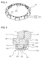
- the holder 27 has a body portion 27c comprising a cover wall 27a which slidably covers an end surface 12c at the outer circumferential portion of the upper arm 12 on an opposite side to the lower arm 11, and a circumferential wall 27b formed continuously with the cover wall 27a and covering an outer circumferential surface 11c of the lower arm 11 and also has fixed portions 27d provided at an end of the circumferential wall 27b and fixed by caulking on an end surface 11e at the outer circumference of the lower arm 11 on an opposite side to the upper arm 12.
- the cover wall 27a is bent at an approximately right angle toward the end surface 12c of the upper arm 12 and is in contact with the end surface 12c of the upper arm 12.
- the lower arm 11 and the upper arm 12 are prevented from coming off each other in the axial direction in a state that they are allowed to rotate relative to each other.
- the end surface 12c and the cover wall 27a slide on each other with a slight clearance therebetween, and in Figures 1 and 5 , the clearance is illustrated to be large in an exaggerated scale.
- the lower arm 11 is not shown, and the holder 27 is illustrated with itself fixed by caulking on the lower arm 11.
- load receiving portions 27e which are cut and bent from the body portion 27c to contact an end surface 11 d at the outer circumferential portion of the lower arm 11 on the upper arm 12 side for supporting a caulking load at the time of a fixing by caulking.
- the load receiving portions 27e formed by cutting and bending parts of the body portion 27c are arranged at plural places at regular intervals in the circumferential direction. Thus, a curve caused by bending is not generated at an end portion of each load receiving portion 27e, so that a large flat portion can be obtained. Therefore, it is unnecessary to newly provide portions supporting the caulking load by enlarging the outer diameters of the lower arm 11 and the holder 27, so that the device can be downsized.
- the load receiving portions are not required to be provided over the whole outer circumferential portion of the holder, thereby realizing a reduction in cost.
- the load receiving portions 27e may not formed to be necessarily at regular intervals in the circumferential direction.
- the fixed portions 27d are provided at the positions corresponding to the load receiving portions 27e in the circumferential direction of the upper arm 12 and the lower arm 11. Thus, when the fixed portions 27d are fixed by caulking, the holder 27 is held reliably and stably, so that the fixing by caulking can be done reliably.
- the cover wall 27a is neither deformed as a result of being pressed strongly on the end surface 12c of the upper arm 12 nor separated from the end surface 12c of the upper arm 12 too far, so that a smooth sliding can be secured between the end surface 12c of the upper arm 12 and the cover wall 27a.
- An annular space 28 of a predetermined capacity is formed between each corner portion connecting the circumferential wall 27b with each load receiving portion 27e and the end surface 11 d at the outer circumferential portion of the lower arm 11 on the upper arm 12 side.
- a locking mechanism 30 is arranged between the lower arm 11 and the upper arm 12. As shown in Figures 2 and 3 , the locking mechanism 30 is composed mainly of three pawls 31 (31A and 31B referred to later) on a circle, a cam 32, a release plate 33 and a spiral spring 34 as urging member (refer to Figure 3 ).
- the pawls 31 comprise three pawls of two kinds which are arranged at equiangular intervals on a surface orthogonal to the rotation axis 01.
- first pawl 31 (hereafter referred to as first pawl 31A) is manufactured by, for example, forging a steel, and as shown in Figure 6 in detail, is provided with a first block 41 and a second block 42 which are formed to be offset from each other as viewed in a side view.
- the first pawl 31A is arranged to locate the first block 41 on the internal surface 22a side of the upper arm 12 and the second block 42 on the axis side of the upper arm 12.
- the opposite width-end portions 31A1 of these first block 41 and second block 42 are formed to be in alignment and to represent parallel straight lines.
- the outward end (the end surface facing the inner gear 23 of the upper arm 12) of the first block 41 is formed with an outer gear 44 being able to mesh with the inner gear 23 of the upper arm 12, while the inward end (the end surface opposite to the outward end) of the first block 41 is formed with an inner cam portion 45 engageable with an outer surface of the cam 32.
- a pawl grooved cam portion 46 is provided to pass through in the thickness direction at about the center portion in the width direction.
- an engaging portion 43 engageable with the protrusion portion 25 of the upper arm 12 is formed on the back side of the second block 42.
- second pawls 31B two remaining pawls 31 are manufactured by, for example, pressing a plate-like steel sheet, and as shown in Figure 7 in detail, each takes a flat shape which closely resembles the shape configured only by the first block 41 of the first pawl 31A by cutting out the second block 42 therefrom, and hence, which does not have any step. That is, the second pawl 31B is formed to be radially shorter by the length of the second block 42 than the first pawl 31A and to be thinner by the thickness of the second block 42. Like the first pawl 31A, the second pawl 31B has the opposite width-end portions 31B1 formed to represent parallel straight lines.
- each second pawl 31B is formed with an outer gear 47 being able to mesh with the inner gear 23 of the upper arm 12.
- the inward end of each second pawl 31B is formed with an inner cam portion 48 engaged with the outer surface of the cam 32.
- an engaging protrusion 49 is provided on an end surface of each second pawl 31B to protrude from a center portion in the width direction.
- each of the inner cam portions 45, 48 is provided with three pressed portions 50a, 50b, 50c on which cam surfaces 55 of the cam 32 act, at a center portion and opposite sides in the circumferential direction of each of the first and second pawls 31A, 31B.
- the pressed portion 50a and the pressed portion 50b, which are provided at the center portion and on a side ahead in a locking rotation direction of the cam 32, of each of the first and second pawls 31A, 31B are constituted by cam shapes each having an inclined surface which comes close to the cam surfaces 55 of the cam 32 with rotation of the cam 32 in the locking rotation direction (counterclockwise in Figure 2 ), whereas the pressed portion 50c which is provided on a side behind in the locking rotation direction of the cam 32 is constituted by an arc surface having its center on the rotation center of the cam 32.
- first and second pawls 31A, 31B are slidably moved in the radial direction of the lower arm 11 and the upper arm 12 by being guided along the guide surfaces 52 of the guide walls 51 and enable the respective outer gears 44, 47 to be disengageably engaged with the inner gear 23.
- the guide walls 51 are formed at internal surfaces thereof with arc surfaces 53 having a center on the rotation axis O1.
- the cam 32 of the locking mechanism 30 is arranged in the round recessed portion 22 of the upper arm 12 to be rotatable about the rotation axis 01 and has a through hole 32a at its center portion. Further, the cam 32 has three cam surfaces 55 on its outer circumference at equiangular intervals. Of these, one cam surface 55 is arranged to be engageable with the respective pressed portions 50a, 50b, 50c of the inner cam portion 45 of the first pawl 31A, while the two remaining cam surfaces 55 are arranged to be engageable with the respective pressed portions 50a, 50b, 50c of the respective inner cam portions 48 of the second pawls 31B.
- Each cam surface 55 comprises two pressing cam segments 55a, 55b contactable with the pressed portions 50a, 50b of each of the first and second pawls 31A, 31B and one centering segment 55c contactable with the pressed portion 50c.
- the two pressing cam segments 55a, 55b and said one centering segment 55c are held at such angular positions that they are respectively brought into contact with the respective pressed portions 50a, 50b, 50c of each of the inner cam portions 45, 48 of the first and second pawls 31A, 31B.
- the pressing cam segments 55a, 55b and the centering segment 55c are moved away from the respective pressed portions 50a, 50b, 50c, and the centering segment 55c is held at such an angular position as to be engaged with the arc surface 53 of the guide wall 51.
- a side surface of the cam 32 protrudes a plurality of engaging protrusions 57 at equiangular intervals, and one of these engaging protrusions 57 is engaged with the pawl grooved cam portion 46 formed in the first pawl 31A.
- the pawl grooved cam portion 46 and the engaging protrusion 57 cooperate to move the first pawl 31A radially inward with rotation of the cam 32 in the locking release rotation direction.
- the engaging protrusions 57 are not necessarily required to be protruded on the same circle at equiangular intervals, but may be protruded on different circles or with arbitrary intervals secured therebetween.
- the release plate 33 made of a thin plate is bodily attached to a side surface of the cam 32, with itself engaged with the engaging protrusions 57, and the release plate 33 has a through hole 33a at its center portion.
- the release plate 33 is attached to the cam 32 in alignment with the second block 42 of the first pawl 31A at a position in the axial direction and slidably faces end surfaces of the second pawls 31B.
- the release plate 33 comprises an approximately ring shape plate held out of contact with the protrusions 25 formed on the upper arm 12, wherein a sector cutout 33b is formed at a part of the ring shape plate, and the first pawl 31A is arranged at the place of the cutout 33b. That is, by cutting off a sector from the ring-like plate by an angular range corresponding to the first pawl 31A, it is prevented that rotation of the cam 32 brings the release plate 33 into interference with the first pawl 31A.
- the release plate 33 is formed on a circle about its rotation center with two release plate grooved cam portions 59 which pass through in the thickness direction. These release plate grooved cam portions 59 are arranged radial outward of the circular position on which the engaging protrusions 57 are arranged, to correspond respectively to the end surfaces of the second pawls 31B.
- the engaging protrusions 49 protruding from the second pawls 31B are respectively engaged with the release plate grooved cam portions 59. Engagements of the release plate grooved cam portions 59 with the engaging protrusions 49 enable the second pawls 31B to be moved radial inward when the release plate 33, together with the cam 32, is rotated in the locking release direction (clockwise in Figure 2 ).
- a hinge shaft 60 is arranged on the rotation axis O1 and rotatably passes through respective through holes 11 a, 32a, 33a, 12b which are formed on the rotation center portions of the lower arm 11, the cam 32, the release plate 33 and the upper arm 12.
- a fitting portion 60a with two flat surfaces formed thereon is formed at about a center portion in the axial direction of the hinge shaft 60.
- the through hole 32a of the cam 32 with the hinge shaft 60 passing therethrough is formed with two flat surfaces to fit on the fitting portion 60a of the hinge shaft 60, so that hinge shaft 60 and the cam 32 are configured to rotate bodily.
- the through hole 32a of the cam 32 is formed to be slightly larger than the fitting portion 60a of the hinge shaft 60, so that a play in the radial direction is provided between both members.
- the cam 32 is slightly movable radially of the hinge shaft 60 within the round recessed portion 22 of the upper arm 12.
- an operating handle 62 is bodily attached to the hinge shaft 60.
- the spiral spring 34 is for urging the cam 32 to rotate in such a direction that the first and second pawls 31A, 31B are brought into engagements with the upper arm 12, and is received in the through hole 11 a of the lower arm 11.
- the spiral spring 34 is formed by, for example, curving a flat wire rod of an approximately rectangular shape into a predetermined spiral shape and is arranged between the lower arm 11 and the cam 32. That is, an outer end portion 34a of the spiral spring 34 is fixedly engaged with a fixing perforation 11 b formed in the lower arm 11, whereas an inner end portion 34b is fixedly engaged with a fixing portion (not shown) provided on an end surface of the cam 32.
- the cam 32 By the urging force of the spiral spring 34, the cam 32 is urged to be rotated relative to the lower arm 11 in the locking rotation direction (counterclockwise in Figure 2 ), causes its cam surfaces 55 to press the first and second pawls 31A, 31B radially outward, and brings the outer gears 44, 47 of the first and second pawls 31A, 31B into engagements with the inner gear 23 of the upper arm 12.
- Figure 2 shows the seat reclining device 10 in the locking state.
- the pressing cam segments 55a, 55b and the centering segments 55c of the cam 32 are respectively in contact with the respective pressed portions 50a, 50b, 50c of the inner cam portions 45, 48 of the first and second pawls 31A 31B, so that the first and second pawls 31A, 31B are being pressed radially outward.
- the first and second pawls 31A, 31B can be pressed at the plurality of pressed portions 50a, 50b, 50c against the inner gear 23 of the upper arm 12 in a stable posture, and hence, can reliably bring the outer gears 44, 47 of the respective pawls 31 into meshing with the inner gear 23 of the upper arm 12.
- the outer gears 44, 47 of the first and second pawls 31A, 31B are made to mesh with the inner gear 23 of the upper arm 12, whereby the upper arm 12 is prevented from rotationally moving relative to the lower arm 11.
- the cam 32 can press the three pawls 31 (31A, 31B) with approximately equal pressing forces. Accordingly, it becomes possible to lock the upper arm 12 and hence, the seatback reliably without looseness.
- the seatback when in the state of the locking released, the seatback is rotated forward relative to the seat cushion beyond a predetermined angle into a so-called forward folded angular range, the protrusion 25 formed on the internal surface of the round recessed portion 24 of the upper arm 12 is positioned between the engaging portion 43 formed on the first pawl 31A and the inner gear 23, as shown in Figure 9 . That is, by being engaged with the protrusion 25 of the upper arm 12 at its engaging portion 43, the first pawl 31A is prevented from moving radially outward.
- the cam 32 tends to press the first pawl 31A in the direction to engage with the inner gear 23 by the action of the spiral spring 34, but the meshing does not take place because the movement of the first pawl 31A is obstructed by the engagement between the protrusion 25 of the upper arm 12 and the engaging portion 43 of the first pawl 31A.
- the rotation of the cam 32 is also obstructed, and the release plate 33 does not rotate, so that the release plate grooved cam portions 59 cause the second pawls 31B to be also held at an out-of-meshing position spaced from the inner gear 23. Accordingly, within the forward folded angular range, the seatback can be rotated without being locked.
- the seatback is returned backward or forward to take a best position for seating by the manipulation of the operating handle 62, and when the operating handle 62 is released at such a position, the first and second pawls 31A, 31B, the cam 32 and the release plate 33 are returned to the state shown in Figure 2 to be brought again into the locking state.
- the load receiving portions 27e formed by cutting and bending parts of the body portion 27c are arranged at plural places in the circumferential direction, it is not required to newly provide portions supporting a caulking load by enlarging the outer diameters of the lower arm 11 and the holder 27, so that the device can be downsized. Further, although the portions supporting the caulking load are required to be precise in the height direction (in the rotational axis direction), it is unnecessary to provide the load receiving portions over the whole outer circumference of the holder 27, thereby resulting in a reduction in cost.
- the load receiving portions 27e supporting the caulking load are provided at the positions corresponding to the fixed portions 27d, and thus, when the fixed portions 27d are caulked by the caulking work, the holder 27 can be held reliably and stably, so that the fixing by caulking can be done reliably.
- the load receiving portions 27e supporting the caulking load are provided at regular intervals in the circumferential direction of the holder 27, and thus, when the fixed portions 27d are caulked by the caulking work, the holder 27 can be held equally and stably in the circumferential direction, so that the fixing by caulking can be done reliably.
- a seat reclining device for vehicle according to the present invention is suitable for use in a vehicle seat which supports a seatback to be angularly adjustable relative to a seat cushion.
Landscapes
- Engineering & Computer Science (AREA)
- Aviation & Aerospace Engineering (AREA)
- Transportation (AREA)
- Mechanical Engineering (AREA)
- Chairs For Special Purposes, Such As Reclining Chairs (AREA)
- Seats For Vehicles (AREA)
Abstract
Description
- The present invention relates to a seat reclining device for vehicle supporting a seatback to be angularly adjustable relative to a seat cushion.
- Heretofore, as seat reclining devices of this kind, there has been known one which is described in Patent Document 1, for example. The device described in Patent Document 1 has a
base member 11 fixed to a seat cushion side of a vehicle seat, a rotatingarm 12 rotatably supported on thebase member 11 and fixed to a seatback, a locking mechanism for locking the rotatingarm 12 not to rotate, an operating lever 15 for bringing the locking mechanism into an unlocking state, and a return spring urging the seatback in a forward tilting direction. The base member is provided at an outer circumferential part thereof with aring member 33 engaging an outer circumferential part of the rotatingarm 12. (refer to symbols described in Patent Document 1). - Patent Document 1:
JP2000-333758 A - In the device described in Patent Document 1, for a stable caulking work, a flat portion as a seat surface constituting a seat for a caulking jig should be properly secured at a place corresponding to a
caulked portion 43 of thering member 33. Thus, unless an annular portion of the base member 11 (the outer circumferential portion with which thecaulked portion 43 of thering member 33 is brought into contact) has a width which is a predetermined value or more in the radius direction, thebase member 11 cannot be held stably during the caulking work. However, since thering member 33 has a structure that it is bent at a plurality of steps to be brought into contact with the annular portion of thebase member 11, a bending curve is produced at the bent portions. Thus, in order to secure the flat portion for the realization of stable holding, the outer diameter of thebase member 11 has to be enlarged as a matter of course, and the annular portion being high in dimensional accuracy has to be provided over the whole circumference of thebase member 11. This gives rise to a problem that the manufacturing cost and the weight increase. - The object of the present invention provides a seat reclining device which enables a caulking work to be done stably without involving increases in weight and cost.
- In order to solve the aforementioned problem, the invention in a seat reclining device for vehicle defined in Claim 1 essentially comprises:
- a lower arm adapted to be supported on either one of a seat cushion side and a seatback side;
- an upper arm supported by the lower arm to be relatively rotatable and adapted to be supported on the other of the seat cushion side and the seatback side;
- a plurality of pawls supported in the lower arm to be radially movable along guide walls and having outer gears disengageably engaged with an inner gear provided on an internal surface of the upper arm;
- a cam for radially moving the pawls by being rotated;
- an urging member engaged with the lower arm at one end and engaged with the cam at the other end and urging the cam in one direction; and
- a holder having a body portion which comprises a cover wall slidably covering an end surface at an outer circumferential portion of the upper arm on an opposite side to the lower arm and a circumferential wall formed continuously with the cover wall and covering an outer circumferential surface of the lower arm; fixed portions provided at an end of the circumferential wall and fixed by caulking on an end surface at an outer circumferential portion of the lower arm on an opposite side to the upper arm; and a plurality of load receiving portions cut and bent from the body portion to contact an end surface at the outer circumferential portion of the lower arm on the upper arm side for supporting a caulking load at the time of a fixing by caulking; the holder being fixed on the outer circumferential portion of the lower arm for permitting relative rotational movement between the lower arm and the upper arm and for preventing one of the lower arm and the upper arm from coming off the other in an axial direction.
- The invention defined in Claim 2 essentially resides in that in the seat reclining device for vehicle defined in Claim 1, the fixed portions are provided at positions which correspond to the load receiving portions in a circumferential direction of the upper arm and the lower arm.
- The invention defined in Claim 3 essentially resides in that in the seat reclining device for vehicle defined in Claim 1 or 2, an annular space of a predetermined capacity is formed between a corner portion connecting the circumferential wall with the load receiving portion and the end surface at the outer circumferential portion of the lower arm on the upper arm side.
- The invention defined in Claim 4 essentially resides in that in the seat reclining device for vehicle defined in any one of Claims 1 to 3, the load receiving portions are provided at regular intervals in a circumferential direction of the holder.
- In the invention according to Claim 1, since the load receiving portions formed by cutting and bending parts of the body portion are arranged at plural places in the circumferential direction, it is not required to newly provide portions supporting the caulking load by enlarging the outer diameters of the lower arm and the holder, so that the device can be downsized. That is, since by being cut and bent, the load receiving portions do not produce bending curves at free ends thereof, flat portions necessary for the load receiving portions can be obtained without enlarging the outer diameters of the lower arm and the holder. Further, although portions supporting the caulking load are required to be precise in a height direction (in a rotational axis direction), it is unnecessary to provide the load receiving portions over the whole circumference of the outer circumferential portion of the holder, thus realizing a reduction in cost.
- In the invention according to Claim 2, the load receiving portions supporting the caulking load are provided at the positions corresponding to the fixed portions. Thus, when the fixed portions are caulking-fixed by a caulking work, the holder can be held reliably and stably, so that the fixing by caulking can be down reliably. Further, the construction is such that the fixed portions are caulked on the lower arm with the load receiving portions receiving the caulking load, and since no load is exerted on the cover wall of the upper arm during the caulking work, the cover wall is not deformed, so that the smooth sliding between the end surface at the outer circumferential portion of the upper arm on the opposite side to the lower arm and the cover wall is not impeded.
- In the invention according to Claim 3, even if the forming of the lower arm causes any burrs to be produced at a corner portion which is defined by the end surface at the outer circumferential portion of the lower arm on the upper arm side and the outer circumferential surface of the lower arm, that is, at a corner portion of the part of the lower arm covered by the load receiving portions, such burrs can be received in the annular space. Thus, it does not take place that the fixing by caulking can be done with the load receiving portions rising or that the burrs bite the load receiving portions, and hence, the dimensional accuracy of the load receiving portions can be secured to be high in the height direction (in the rotational axis direction).
- In the invention according to Claim 4, the load receiving portions supporting the caulking load are provided at regular intervals in the circumferential direction of the holder, and thus, when the fixed portions are caulking-fixed by the caulking work, the holder can be held uniformly and stably in the circumferential direction, so that the fixing by caulking can be done reliably.
-
- [
Figure 1 ] is a sectional view, taken along a surface including the rotational axis of ahinge shaft 60, of a seat reclining device showing an embodiment of the present invention. - [
Figure 2 ] is a sectional view taken along the line A-A inFigure 1 . - [
Figure 3 ] is an exploded view of the seat reclining device inFigure 1 . - [
Figures 4 ] is a perspective view showing a holder. - [
Figures 5 ] is a sectional view showing the holder fixed by caulking on the lower arm. - [
Figure 6 ] is a detail view showing a first pawl, wherein (A) is a front view of the first pawl and (B) is a side view of the first pawl as viewed in the B direction. - [
Figure 7 ] is a detail view showing a second pawl, wherein (A) is a front view of the second pawl and (B) is a side view of the second pawl as viewed in the B direction. - [
Figure 8 ] is an operational state view ofFigure 2 showing the seat reclining device in an unlocked state. - [
Figure 9 ] is an operational state view ofFigure 2 showing the seat reclining device in a free state. - Hereafter, an embodiment of the present invention will be described with reference to the drawings.
- As shown in
Figures 1-3 , a seat recliningdevice 10 is provided with alower arm 11 and anupper arm 12 which are disc-like. Thelower arm 11 is secured to a seat cushion for vehicle, while theupper arm 12 is secured to a seatback. - The
lower arm 11 is provided with a round recessedportion 21 formed by half blanking to open toward theupper arm 12 and has a throughhole 11 a at its center portion. The round recessedportion 21 of thelower arm 11 has aninternal surface 21 a placing its center on a rotation axis O1 of theupper arm 12 and thelower arm 11. Theupper arm 12 is fitted so that itsouter surface 12a is in slidable contact with theinternal surface 21 a of thelower arm 11. - On the other hand, the
upper arm 12 is provided with a round recessedportion 22 formed by half blanking to open toward thelower arm 11 and has a throughhole 12b at its center portion. The round recessedportion 22 of theupper arm 12 has aninternal surface 22a placing its center on the rotation axis O1. Theinternal surface 22a of the round recessedportion 22 is formed with aninner gear 23 over the whole circumference. On the inner side of therecessed portion 22, a round recessedportion 24 is formed by half blanking on a circle concentric with the round recessedportion 22. On aninternal surface 24a of the round recessedportion 24,protrusions 25 are formed at two places in the circumferential direction to extend toward therotation axis 01, as shown inFigure 2 . - As shown in
Figures 1 and5 , theouter surface 12a of theupper arm 12 is relatively rotatably fitted in theinternal surface 21 a of thelower arm 11, and a part of theouter surface 12a of theupper arm 12 is protruded from an end surface of thelower arm 11. Aholder 27 made of a metal plate is secured on the outer circumference of thelower arm 11. - As shown in
Figure 1 ,4 and 5 , theholder 27 has abody portion 27c comprising acover wall 27a which slidably covers anend surface 12c at the outer circumferential portion of theupper arm 12 on an opposite side to thelower arm 11, and acircumferential wall 27b formed continuously with thecover wall 27a and covering an outercircumferential surface 11c of thelower arm 11 and also has fixedportions 27d provided at an end of thecircumferential wall 27b and fixed by caulking on anend surface 11e at the outer circumference of thelower arm 11 on an opposite side to theupper arm 12. Thecover wall 27a is bent at an approximately right angle toward theend surface 12c of theupper arm 12 and is in contact with theend surface 12c of theupper arm 12. Thus, thelower arm 11 and theupper arm 12 are prevented from coming off each other in the axial direction in a state that they are allowed to rotate relative to each other. Theend surface 12c and thecover wall 27a slide on each other with a slight clearance therebetween, and inFigures 1 and5 , the clearance is illustrated to be large in an exaggerated scale. Also inFigure 4 , thelower arm 11 is not shown, and theholder 27 is illustrated with itself fixed by caulking on thelower arm 11. - There are formed a plurality of
load receiving portions 27e which are cut and bent from thebody portion 27c to contact anend surface 11 d at the outer circumferential portion of thelower arm 11 on theupper arm 12 side for supporting a caulking load at the time of a fixing by caulking. Theload receiving portions 27e formed by cutting and bending parts of thebody portion 27c are arranged at plural places at regular intervals in the circumferential direction. Thus, a curve caused by bending is not generated at an end portion of eachload receiving portion 27e, so that a large flat portion can be obtained. Therefore, it is unnecessary to newly provide portions supporting the caulking load by enlarging the outer diameters of thelower arm 11 and theholder 27, so that the device can be downsized. Further, although the portions supporting the caulking load should be precise in the height direction (in the rotational axis direction), the load receiving portions are not required to be provided over the whole outer circumferential portion of the holder, thereby realizing a reduction in cost. Theload receiving portions 27e may not formed to be necessarily at regular intervals in the circumferential direction. - The fixed
portions 27d are provided at the positions corresponding to theload receiving portions 27e in the circumferential direction of theupper arm 12 and thelower arm 11. Thus, when the fixedportions 27d are fixed by caulking, theholder 27 is held reliably and stably, so that the fixing by caulking can be done reliably. - Further, since the fixed
portions 27d are caulked on thelower arm 11 with theload receiving portions 27e receiving the caulking load, it does not occur that the caulking load is exerted on thecover wall 27a during the caulking work. Therefore, thecover wall 27a is neither deformed as a result of being pressed strongly on theend surface 12c of theupper arm 12 nor separated from theend surface 12c of theupper arm 12 too far, so that a smooth sliding can be secured between theend surface 12c of theupper arm 12 and thecover wall 27a. - An
annular space 28 of a predetermined capacity is formed between each corner portion connecting thecircumferential wall 27b with eachload receiving portion 27e and theend surface 11 d at the outer circumferential portion of thelower arm 11 on theupper arm 12 side. Thus, even if burrs are produced at acorner portion 11f which is defined by theend surface 11d at the outer circumferential portion of thelower arm 11 on theupper arm 12 side and the outercircumferential surface 11c of thelower arm 11, the burrs are received in theannular spaces 28. Thus, it does not occur that the fixing by caulking is done with theload receiving portions 27e rising or that the burrs bite theload receiving portions 27e, and hence, the dimensional accuracy of theload receiving portions 27e can be secured to be high in the height direction (in the rotational axis direction). - A
locking mechanism 30 is arranged between thelower arm 11 and theupper arm 12. As shown inFigures 2 and3 , thelocking mechanism 30 is composed mainly of three pawls 31 (31A and 31B referred to later) on a circle, acam 32, arelease plate 33 and aspiral spring 34 as urging member (refer toFigure 3 ). The pawls 31 comprise three pawls of two kinds which are arranged at equiangular intervals on a surface orthogonal to therotation axis 01. - One pawl 31 (hereafter referred to as
first pawl 31A) is manufactured by, for example, forging a steel, and as shown inFigure 6 in detail, is provided with afirst block 41 and asecond block 42 which are formed to be offset from each other as viewed in a side view. Thefirst pawl 31A is arranged to locate thefirst block 41 on theinternal surface 22a side of theupper arm 12 and thesecond block 42 on the axis side of theupper arm 12. The opposite width-end portions 31A1 of thesefirst block 41 andsecond block 42 are formed to be in alignment and to represent parallel straight lines. The outward end (the end surface facing theinner gear 23 of the upper arm 12) of thefirst block 41 is formed with anouter gear 44 being able to mesh with theinner gear 23 of theupper arm 12, while the inward end (the end surface opposite to the outward end) of thefirst block 41 is formed with aninner cam portion 45 engageable with an outer surface of thecam 32. Further, in thesecond block 42, a pawl groovedcam portion 46 is provided to pass through in the thickness direction at about the center portion in the width direction. And, an engagingportion 43 engageable with theprotrusion portion 25 of theupper arm 12 is formed on the back side of thesecond block 42. - On the other hand, of the three, two remaining pawls 31 (hereafter referred to as
second pawls 31B) are manufactured by, for example, pressing a plate-like steel sheet, and as shown inFigure 7 in detail, each takes a flat shape which closely resembles the shape configured only by thefirst block 41 of thefirst pawl 31A by cutting out thesecond block 42 therefrom, and hence, which does not have any step. That is, thesecond pawl 31B is formed to be radially shorter by the length of thesecond block 42 than thefirst pawl 31A and to be thinner by the thickness of thesecond block 42. Like thefirst pawl 31A, thesecond pawl 31B has the opposite width-end portions 31B1 formed to represent parallel straight lines. The outward end of eachsecond pawl 31B is formed with anouter gear 47 being able to mesh with theinner gear 23 of theupper arm 12. The inward end of eachsecond pawl 31B is formed with aninner cam portion 48 engaged with the outer surface of thecam 32. Further, an engagingprotrusion 49 is provided on an end surface of eachsecond pawl 31B to protrude from a center portion in the width direction. - The
inner cam portion 45 formed at a stepped portion of the aforementionedfirst pawl 31A and theinner cam portion 48 formed at the inward end of thesecond pawl 31B are formed to take the same shape. Specifically, as shown inFigures 6(A) and 7(A) , each of theinner cam portions portions cam 32 act, at a center portion and opposite sides in the circumferential direction of each of the first andsecond pawls portion 50a and the pressed portion 50b, which are provided at the center portion and on a side ahead in a locking rotation direction of thecam 32, of each of the first andsecond pawls cam 32 with rotation of thecam 32 in the locking rotation direction (counterclockwise inFigure 2 ), whereas the pressedportion 50c which is provided on a side behind in the locking rotation direction of thecam 32 is constituted by an arc surface having its center on the rotation center of thecam 32. - In the round recessed
portion 21 of thelower arm 11, threeguide walls 51 are arranged at equiangular intervals, and guidesurfaces 52 which slidably guide the opposite width-end portions 31A1, 31B1 (refer toFigures 6 and 7 ) of each of the first andsecond pawls guide walls 51 are formed in parallel to face each other. Thus, the first andsecond pawls lower arm 11 and theupper arm 12 by being guided along the guide surfaces 52 of theguide walls 51 and enable the respectiveouter gears inner gear 23. Theguide walls 51 are formed at internal surfaces thereof with arc surfaces 53 having a center on the rotation axis O1. - The
cam 32 of thelocking mechanism 30 is arranged in the round recessedportion 22 of theupper arm 12 to be rotatable about therotation axis 01 and has a throughhole 32a at its center portion. Further, thecam 32 has threecam surfaces 55 on its outer circumference at equiangular intervals. Of these, onecam surface 55 is arranged to be engageable with the respective pressedportions inner cam portion 45 of thefirst pawl 31A, while the two remaining cam surfaces 55 are arranged to be engageable with the respective pressedportions inner cam portions 48 of thesecond pawls 31B. - Each
cam surface 55 comprises twopressing cam segments portions 50a, 50b of each of the first andsecond pawls segment 55c contactable with the pressedportion 50c. When thecam 32 is rotated in the locking rotation direction, the twopressing cam segments segment 55c are held at such angular positions that they are respectively brought into contact with the respective pressedportions inner cam portions second pawls cam 32 is rotated in a direction to release the locking, thepressing cam segments segment 55c are moved away from the respective pressedportions segment 55c is held at such an angular position as to be engaged with thearc surface 53 of theguide wall 51. - A side surface of the
cam 32 protrudes a plurality of engagingprotrusions 57 at equiangular intervals, and one of these engagingprotrusions 57 is engaged with the pawl groovedcam portion 46 formed in thefirst pawl 31A. The pawl groovedcam portion 46 and the engagingprotrusion 57 cooperate to move thefirst pawl 31A radially inward with rotation of thecam 32 in the locking release rotation direction. The engagingprotrusions 57 are not necessarily required to be protruded on the same circle at equiangular intervals, but may be protruded on different circles or with arbitrary intervals secured therebetween. - The
release plate 33 made of a thin plate is bodily attached to a side surface of thecam 32, with itself engaged with the engagingprotrusions 57, and therelease plate 33 has a throughhole 33a at its center portion. Therelease plate 33 is attached to thecam 32 in alignment with thesecond block 42 of thefirst pawl 31A at a position in the axial direction and slidably faces end surfaces of thesecond pawls 31B. Therelease plate 33 comprises an approximately ring shape plate held out of contact with theprotrusions 25 formed on theupper arm 12, wherein asector cutout 33b is formed at a part of the ring shape plate, and thefirst pawl 31A is arranged at the place of thecutout 33b. That is, by cutting off a sector from the ring-like plate by an angular range corresponding to thefirst pawl 31A, it is prevented that rotation of thecam 32 brings therelease plate 33 into interference with thefirst pawl 31A. - The
release plate 33 is formed on a circle about its rotation center with two release plate groovedcam portions 59 which pass through in the thickness direction. These release plate groovedcam portions 59 are arranged radial outward of the circular position on which the engagingprotrusions 57 are arranged, to correspond respectively to the end surfaces of thesecond pawls 31B. The engagingprotrusions 49 protruding from thesecond pawls 31B are respectively engaged with the release plate groovedcam portions 59. Engagements of the release plate groovedcam portions 59 with the engagingprotrusions 49 enable thesecond pawls 31B to be moved radial inward when therelease plate 33, together with thecam 32, is rotated in the locking release direction (clockwise inFigure 2 ). - As shown in
Figure 3 , ahinge shaft 60 is arranged on the rotation axis O1 and rotatably passes through respective throughholes lower arm 11, thecam 32, therelease plate 33 and theupper arm 12. Afitting portion 60a with two flat surfaces formed thereon is formed at about a center portion in the axial direction of thehinge shaft 60. The throughhole 32a of thecam 32 with thehinge shaft 60 passing therethrough is formed with two flat surfaces to fit on thefitting portion 60a of thehinge shaft 60, so thathinge shaft 60 and thecam 32 are configured to rotate bodily. Here, as shown inFigure 2 , the throughhole 32a of thecam 32 is formed to be slightly larger than thefitting portion 60a of thehinge shaft 60, so that a play in the radial direction is provided between both members. Thus, thecam 32 is slightly movable radially of thehinge shaft 60 within the round recessedportion 22 of theupper arm 12. Further, on one end of thehinge shaft 60, anoperating handle 62 is bodily attached to thehinge shaft 60. - The
spiral spring 34 is for urging thecam 32 to rotate in such a direction that the first andsecond pawls upper arm 12, and is received in the throughhole 11 a of thelower arm 11. As shown inFigure 3 , thespiral spring 34 is formed by, for example, curving a flat wire rod of an approximately rectangular shape into a predetermined spiral shape and is arranged between thelower arm 11 and thecam 32. That is, anouter end portion 34a of thespiral spring 34 is fixedly engaged with a fixingperforation 11 b formed in thelower arm 11, whereas aninner end portion 34b is fixedly engaged with a fixing portion (not shown) provided on an end surface of thecam 32. - By the urging force of the
spiral spring 34, thecam 32 is urged to be rotated relative to thelower arm 11 in the locking rotation direction (counterclockwise inFigure 2 ), causes its cam surfaces 55 to press the first andsecond pawls outer gears second pawls inner gear 23 of theupper arm 12. - Next, description will be made regarding the operation of the
seat reclining device 10 constructed as described above. -
Figure 2 shows theseat reclining device 10 in the locking state. In this state, thepressing cam segments segments 55c of thecam 32 are respectively in contact with the respective pressedportions inner cam portions second pawls 31Asecond pawls second pawls portions inner gear 23 of theupper arm 12 in a stable posture, and hence, can reliably bring the outer gears 44, 47 of the respective pawls 31 into meshing with theinner gear 23 of theupper arm 12. In this manner, the outer gears 44, 47 of the first andsecond pawls inner gear 23 of theupper arm 12, whereby theupper arm 12 is prevented from rotationally moving relative to thelower arm 11. At this time, because of being radially movable relative to thehinge shaft 60 within the round recessedportion 21, thecam 32 can press the three pawls 31 (31A, 31B) with approximately equal pressing forces. Accordingly, it becomes possible to lock theupper arm 12 and hence, the seatback reliably without looseness. - In this state, when the
hinge shaft 60 is rotated clockwise inFigure 2 by manipulating theoperating handle 62, thecam 32 and therelease plate 33 are bodily rotated against the urging force of thespiral spring 34. As a result, thepressing cam segments inner cam portions second pawls segments 55c are also displaced in a direction not to interfere with theinner cam portions cam portion 46 of thefirst pawl 31A and the engagingprotrusion 57 of thecam 32 causes thefirst pawl 31A to be withdrawn toward therotation axis 01 side along the guide surfaces 52 of theguide walls 51, whereby as shown inFigure 8 , meshing is released between theouter gear 44 of thefirst pawl 31A and theinner gear 23. At the same time, the engagement actions between the engagingprotrusions 49 of thesecond pawls 31B and the release plate groovedcam portions 59 cause thesecond pawls 31B to be withdrawn toward therotation axis 01 side along the guide surfaces 52 of theguide walls 51, whereby meshing is released between theouter gears 47 of thesecond pawls 31B and theinner gear 23. - Thus, it becomes possible to rotationally move the seatback to a desired angular position relative to the seat cushion. At this time, the centering
segments 55c of thecam 32 which are in a set of three are held respectively engaged with theinternal surfaces 53 of theguide walls 51, so that thecam 32 is centered by theinternal surfaces 53 of theguide walls 51. As a result, the clearances between theouter gears second pawls inner gear 23 become approximately equal, so that the malfunction in rotational movement or the generation of a strange sound can be prevented from being caused by an interference of addendums on one of the pawls 31 with addendums of theinner gear 23. - Furthermore, when in the state of the locking released, the seatback is rotated forward relative to the seat cushion beyond a predetermined angle into a so-called forward folded angular range, the
protrusion 25 formed on the internal surface of the round recessedportion 24 of theupper arm 12 is positioned between the engagingportion 43 formed on thefirst pawl 31A and theinner gear 23, as shown inFigure 9 . That is, by being engaged with theprotrusion 25 of theupper arm 12 at its engagingportion 43, thefirst pawl 31A is prevented from moving radially outward. When the operatinghandle 62 is released in this state, thecam 32 tends to press thefirst pawl 31A in the direction to engage with theinner gear 23 by the action of thespiral spring 34, but the meshing does not take place because the movement of thefirst pawl 31A is obstructed by the engagement between theprotrusion 25 of theupper arm 12 and the engagingportion 43 of thefirst pawl 31A. At the same time, as a result that the radial movement of thefirst pawl 31A is obstructed, the rotation of thecam 32 is also obstructed, and therelease plate 33 does not rotate, so that the release plate groovedcam portions 59 cause thesecond pawls 31B to be also held at an out-of-meshing position spaced from theinner gear 23. Accordingly, within the forward folded angular range, the seatback can be rotated without being locked. - From the forward folded state or the reclined state, the seatback is returned backward or forward to take a best position for seating by the manipulation of the
operating handle 62, and when the operatinghandle 62 is released at such a position, the first andsecond pawls cam 32 and therelease plate 33 are returned to the state shown inFigure 2 to be brought again into the locking state. - As described above, according to the present embodiment, the following effects can be attained.
- Since the
load receiving portions 27e formed by cutting and bending parts of thebody portion 27c are arranged at plural places in the circumferential direction, it is not required to newly provide portions supporting a caulking load by enlarging the outer diameters of thelower arm 11 and theholder 27, so that the device can be downsized. Further, although the portions supporting the caulking load are required to be precise in the height direction (in the rotational axis direction), it is unnecessary to provide the load receiving portions over the whole outer circumference of theholder 27, thereby resulting in a reduction in cost. - Further, the
load receiving portions 27e supporting the caulking load are provided at the positions corresponding to the fixedportions 27d, and thus, when the fixedportions 27d are caulked by the caulking work, theholder 27 can be held reliably and stably, so that the fixing by caulking can be done reliably. - Furthermore, even if burrs are formed at the
corner portion 11f which is defined by theend surface 11 d at the outer circumferential portion of thelower arm 11 on theupper arm 12 side and the outercircumferential surface 11 c of thelower arm 11, such burrs are received in theannular spaces 28. Therefore, it dose not occur that theload receiving portions 27e rise at the time of the fixing by caulking, so that the dimensional accuracy of theload receiving portions 27e can be secured to be precise in the height direction (in the rotational axis direction).
In addition, theload receiving portions 27e supporting the caulking load are provided at regular intervals in the circumferential direction of theholder 27, and thus, when the fixedportions 27d are caulked by the caulking work, theholder 27 can be held equally and stably in the circumferential direction, so that the fixing by caulking can be done reliably. - A seat reclining device for vehicle according to the present invention is suitable for use in a vehicle seat which supports a seatback to be angularly adjustable relative to a seat cushion.
-
- 10
- seat reclining device
- 11
- lower arm
- 12
- upper arm
- 23
- inner gear
- 27
- holder
- 27a
- cover wall
- 27b
- circumferential wall
- 27c
- body portion
- 27d
- fixed portion
- 27e
- load receiving portion
- 28
- annular space
- 30
- locking mechanism
- 31A, 31B
- pawl
- 32
- cam
- 34
- spiral spring (urging member)
- 44, 47
- outer gear
- 45, 48
- inner cam surface
- 46
- pawl grooved cam portion
- 49
- engaging protrusion
- 51
- guide wall
- 55
- cam surface
- 57
- engaging protrusion
- 59
- release plate grooved cam portion
- 60
- hinge shaft
Claims (4)
- A seat reclining device for vehicle, comprising:a lower arm adapted to be supported on either one of a seat cushion side and a seatback side;an upper arm supported by the lower arm to be relatively rotatable and adapted to be supported on the other of the seat cushion side and the seatback side;a plurality of pawls supported in the lower arm to be radially movable along guide walls and having outer gears disengageably engaged with an inner gear provided on an internal surface of the upper arm;a cam for radially moving the pawls by being rotated;an urging member engaged with the lower arm at one end and engaged with the cam at the other end and urging the cam in one direction; anda holder having a body portion which comprises a cover wall slidably covering an end surface at an outer circumferential portion of the upper arm on an opposite side to the lower arm and a circumferential wall formed continuously with the cover wall and covering an outer circumferential surface of the lower arm; fixed portions provided at an end of the circumferential wall and fixed by caulking on an end surface at an outer circumferential portion of the lower arm on an opposite side to the upper arm; and a plurality of load receiving portions cut and bent from the body portion to contact an end surface at the outer circumferential portion of the lower arm on the upper arm side for supporting a caulking load at the time of a fixing by caulking; the holder being fixed on the outer circumferential portion of the lower arm for permitting relative rotational movement between the lower arm and the upper arm and for preventing one of the lower arm and the upper arm from coming off the other in an axial direction.
- The seat reclining device for vehicle in Claim 1, characterized in that the fixed portions are provided at positions which correspond to the load receiving portions in a circumferential direction of the upper arm and the lower arm.
- The seat reclining device for vehicle in Claim 1 or 2, characterized in that an annular space of a predetermined capacity is formed between a corner portion connecting the body portion with the load receiving portion and the end surface at the outer circumferential portion of the lower arm on the upper arm side.
- The seat reclining device for vehicle in any one of Claims 1 to 3, characterized in that the load receiving portions are provided at regular intervals in a circumferential direction of the holder.
Applications Claiming Priority (2)
| Application Number | Priority Date | Filing Date | Title |
|---|---|---|---|
| JP2009192169A JP5326930B2 (en) | 2009-08-21 | 2009-08-21 | Vehicle seat reclining device |
| PCT/JP2010/063059 WO2011021496A1 (en) | 2009-08-21 | 2010-08-03 | Seat reclining device for vehicle |
Publications (3)
| Publication Number | Publication Date |
|---|---|
| EP2468565A1 true EP2468565A1 (en) | 2012-06-27 |
| EP2468565A4 EP2468565A4 (en) | 2012-06-27 |
| EP2468565B1 EP2468565B1 (en) | 2013-05-29 |
Family
ID=43606951
Family Applications (1)
| Application Number | Title | Priority Date | Filing Date |
|---|---|---|---|
| EP10809841.9A Not-in-force EP2468565B1 (en) | 2009-08-21 | 2010-08-03 | Seat reclining device for vehicle |
Country Status (5)
| Country | Link |
|---|---|
| US (1) | US8430453B2 (en) |
| EP (1) | EP2468565B1 (en) |
| JP (1) | JP5326930B2 (en) |
| CN (1) | CN102438856B (en) |
| WO (1) | WO2011021496A1 (en) |
Families Citing this family (14)
| Publication number | Priority date | Publication date | Assignee | Title |
|---|---|---|---|---|
| KR101739314B1 (en) * | 2011-05-11 | 2017-05-24 | 주식회사다스 | Recliner of vehicles seat |
| JP5434969B2 (en) * | 2011-06-14 | 2014-03-05 | アイシン精機株式会社 | Vehicle seat reclining device |
| US20130076094A1 (en) * | 2011-09-27 | 2013-03-28 | Imasen Electric Industrial Co., Ltd. | Reclining apparatus |
| JP5821650B2 (en) * | 2012-01-19 | 2015-11-24 | アイシン精機株式会社 | Vehicle seat reclining device |
| KR101296063B1 (en) | 2012-06-28 | 2013-08-12 | 주식회사다스 | Recliner of vehicle seet |
| JP6018859B2 (en) * | 2012-09-19 | 2016-11-02 | シロキ工業株式会社 | Reclining device |
| JP2014057803A (en) * | 2012-09-19 | 2014-04-03 | Shiroki Corp | Seat reclining device |
| JP5969873B2 (en) * | 2012-09-27 | 2016-08-17 | 富士機工株式会社 | Vehicle seat reclining device |
| EP2977257B1 (en) * | 2013-03-22 | 2017-04-19 | Aisin Seiki Kabushiki Kaisha | Seat reclining device for vehicles |
| JP6431254B2 (en) * | 2013-09-30 | 2018-11-28 | トヨタ紡織株式会社 | Recliner |
| JP6488746B2 (en) * | 2015-02-10 | 2019-03-27 | アイシン精機株式会社 | Vehicle seat reclining device |
| KR101959006B1 (en) * | 2017-06-20 | 2019-03-18 | 현대트랜시스(주) | Recliner for vehicle seat |
| US10611273B2 (en) * | 2017-10-09 | 2020-04-07 | Faurecia Automotive Seating, Llc | Recliner system for a vehicle seat |
| KR102011089B1 (en) * | 2017-12-26 | 2019-08-14 | 현대트랜시스(주) | Seat recliner for vehicle and method for producing the same |
Family Cites Families (26)
| Publication number | Priority date | Publication date | Assignee | Title |
|---|---|---|---|---|
| FR2704810B1 (en) * | 1993-05-07 | 1995-07-07 | Bfa | ARTICULATION FOR MOTOR VEHICLE SEATS. |
| JP4265024B2 (en) * | 1998-06-22 | 2009-05-20 | トヨタ紡織株式会社 | Reclining device |
| FR2790230B1 (en) | 1999-02-25 | 2002-05-24 | Faure Bertrand Equipements Sa | ARTICULATION MECHANISM FOR VEHICLE SEAT AND SEAT HAVING SUCH A MECHANISM |
| JP2000333756A (en) * | 1999-05-28 | 2000-12-05 | Fuji Kiko Co Ltd | Vehicle seat reclining device |
| JP3520808B2 (en) * | 1999-05-31 | 2004-04-19 | ジョンソン コントロールズ オートモーティブ システムズ株式会社 | Reclining device |
| JP4374657B2 (en) * | 1999-06-08 | 2009-12-02 | アイシン精機株式会社 | Seat reclining device |
| JP3815537B2 (en) * | 1999-12-03 | 2006-08-30 | 株式会社今仙電機製作所 | Reclining device |
| JP4670134B2 (en) * | 2000-09-28 | 2011-04-13 | アイシン精機株式会社 | Seat reclining device |
| JP3767387B2 (en) * | 2001-01-23 | 2006-04-19 | トヨタ紡織株式会社 | Reclining device |
| JP4770067B2 (en) * | 2001-06-07 | 2011-09-07 | トヨタ紡織株式会社 | Seat reclining device |
| JP3979132B2 (en) * | 2002-03-13 | 2007-09-19 | トヨタ紡織株式会社 | Setting method of sliding clearance in reclining device |
| JP3991780B2 (en) * | 2002-06-19 | 2007-10-17 | アイシン精機株式会社 | Seat reclining device |
| JP4186610B2 (en) * | 2002-12-10 | 2008-11-26 | トヨタ紡織株式会社 | Reclining device |
| KR100513576B1 (en) * | 2003-02-18 | 2005-09-13 | 주식회사 오스템 | Round type recliner for vehicles |
| CN2716063Y (en) * | 2004-04-07 | 2005-08-10 | 湖北中航精机科技股份有限公司 | Plate spring type armchair angle regulating and back-rest folder nuclear installation |
| JP4693525B2 (en) * | 2005-07-05 | 2011-06-01 | シロキ工業株式会社 | Recliner holder manufacturing method |
| JP4716097B2 (en) * | 2005-07-27 | 2011-07-06 | アイシン精機株式会社 | Locking device and seat reclining device |
| US7380882B2 (en) * | 2005-08-22 | 2008-06-03 | Delta Kogyo Co., Ltd. | Recliner adjuster |
| CN1923565B (en) * | 2005-08-31 | 2010-09-29 | 三角洲工业株式会社 | Incline adjustment device |
| JP4882362B2 (en) * | 2005-12-14 | 2012-02-22 | アイシン精機株式会社 | Vehicle seat reclining device |
| JP4308859B2 (en) | 2007-02-20 | 2009-08-05 | 株式会社今仙電機製作所 | Reclining device |
| JP5177134B2 (en) * | 2007-05-08 | 2013-04-03 | トヨタ紡織株式会社 | Connecting device |
| JP2009072413A (en) * | 2007-09-21 | 2009-04-09 | Aisin Seiki Co Ltd | Vehicle seat reclining device |
| US8267476B2 (en) * | 2007-11-09 | 2012-09-18 | Toyota Boshoku Kabushiki Kaisha | Vehicle seat reclining device |
| JP5176560B2 (en) * | 2008-01-21 | 2013-04-03 | トヨタ紡織株式会社 | Vehicle seat coupling device |
| JP5821654B2 (en) * | 2011-02-24 | 2015-11-24 | アイシン精機株式会社 | Vehicle seat reclining device |
-
2009
- 2009-08-21 JP JP2009192169A patent/JP5326930B2/en not_active Expired - Fee Related
-
2010
- 2010-08-03 CN CN2010800350471A patent/CN102438856B/en not_active Expired - Fee Related
- 2010-08-03 WO PCT/JP2010/063059 patent/WO2011021496A1/en not_active Ceased
- 2010-08-03 EP EP10809841.9A patent/EP2468565B1/en not_active Not-in-force
- 2010-08-03 US US13/390,447 patent/US8430453B2/en not_active Expired - Fee Related
Also Published As
| Publication number | Publication date |
|---|---|
| JP2011042276A (en) | 2011-03-03 |
| WO2011021496A1 (en) | 2011-02-24 |
| CN102438856A (en) | 2012-05-02 |
| EP2468565A4 (en) | 2012-06-27 |
| EP2468565B1 (en) | 2013-05-29 |
| US8430453B2 (en) | 2013-04-30 |
| CN102438856B (en) | 2013-07-24 |
| US20120139319A1 (en) | 2012-06-07 |
| JP5326930B2 (en) | 2013-10-30 |
Similar Documents
| Publication | Publication Date | Title |
|---|---|---|
| EP2468565B1 (en) | Seat reclining device for vehicle | |
| US8002353B2 (en) | Vehicle seat reclining apparatus | |
| JP5125836B2 (en) | Seat reclining device | |
| JP5434969B2 (en) | Vehicle seat reclining device | |
| US7823978B2 (en) | Reclining device | |
| EP2322378B1 (en) | Seat reclining apparatus | |
| US7874622B2 (en) | Vehicle seat reclining device | |
| US8870287B2 (en) | Seat reclining device for vehicle | |
| JP2011509875A (en) | Circular reclining mechanism | |
| KR20140044331A (en) | Disc recliner with internal leaf springs | |
| JP2010022400A (en) | Seat reclining device | |
| EP2524839A1 (en) | Seat reclining apparatus for vehicle | |
| JP4497069B2 (en) | Fitting device | |
| JP4255811B2 (en) | Reclining device | |
| JP4763330B2 (en) | Reclining device | |
| JP5596472B2 (en) | Reclining device | |
| JP5104321B2 (en) | Vehicle seat coupling device | |
| JP2007082928A (en) | Joint device | |
| JP4824938B2 (en) | Reclining device | |
| JP2003009979A (en) | Seat reclining device for vehicle | |
| JP5817436B2 (en) | Reclining device | |
| JP2011173577A (en) | Reclining device | |
| JP2002272551A (en) | Vehicle seat reclining device | |
| JP2010227188A (en) | Vehicle seat reclining device | |
| JP2011111012A (en) | Reclining device of vehicle seat |
Legal Events
| Date | Code | Title | Description |
|---|---|---|---|
| PUAI | Public reference made under article 153(3) epc to a published international application that has entered the european phase |
Free format text: ORIGINAL CODE: 0009012 |
|
| 17P | Request for examination filed |
Effective date: 20120130 |
|
| A4 | Supplementary search report drawn up and despatched |
Effective date: 20120507 |
|
| AK | Designated contracting states |
Kind code of ref document: A1 Designated state(s): AL AT BE BG CH CY CZ DE DK EE ES FI FR GB GR HR HU IE IS IT LI LT LU LV MC MK MT NL NO PL PT RO SE SI SK SM TR |
|
| DAX | Request for extension of the european patent (deleted) | ||
| GRAP | Despatch of communication of intention to grant a patent |
Free format text: ORIGINAL CODE: EPIDOSNIGR1 |
|
| RIC1 | Information provided on ipc code assigned before grant |
Ipc: B60N 2/235 20060101ALI20121128BHEP Ipc: B60N 2/22 20060101AFI20121128BHEP |
|
| GRAS | Grant fee paid |
Free format text: ORIGINAL CODE: EPIDOSNIGR3 |
|
| GRAA | (expected) grant |
Free format text: ORIGINAL CODE: 0009210 |
|
| AK | Designated contracting states |
Kind code of ref document: B1 Designated state(s): AL AT BE BG CH CY CZ DE DK EE ES FI FR GB GR HR HU IE IS IT LI LT LU LV MC MK MT NL NO PL PT RO SE SI SK SM TR |
|
| REG | Reference to a national code |
Ref country code: GB Ref legal event code: FG4D |
|
| REG | Reference to a national code |
Ref country code: CH Ref legal event code: EP |
|
| REG | Reference to a national code |
Ref country code: AT Ref legal event code: REF Ref document number: 614160 Country of ref document: AT Kind code of ref document: T Effective date: 20130615 |
|
| REG | Reference to a national code |
Ref country code: IE Ref legal event code: FG4D |
|
| REG | Reference to a national code |
Ref country code: DE Ref legal event code: R096 Ref document number: 602010007440 Country of ref document: DE Effective date: 20130725 |
|
| REG | Reference to a national code |
Ref country code: AT Ref legal event code: MK05 Ref document number: 614160 Country of ref document: AT Kind code of ref document: T Effective date: 20130529 |
|
| REG | Reference to a national code |
Ref country code: LT Ref legal event code: MG4D |
|
| PG25 | Lapsed in a contracting state [announced via postgrant information from national office to epo] |
Ref country code: IS Free format text: LAPSE BECAUSE OF FAILURE TO SUBMIT A TRANSLATION OF THE DESCRIPTION OR TO PAY THE FEE WITHIN THE PRESCRIBED TIME-LIMIT Effective date: 20130929 Ref country code: ES Free format text: LAPSE BECAUSE OF FAILURE TO SUBMIT A TRANSLATION OF THE DESCRIPTION OR TO PAY THE FEE WITHIN THE PRESCRIBED TIME-LIMIT Effective date: 20130909 Ref country code: SE Free format text: LAPSE BECAUSE OF FAILURE TO SUBMIT A TRANSLATION OF THE DESCRIPTION OR TO PAY THE FEE WITHIN THE PRESCRIBED TIME-LIMIT Effective date: 20130529 Ref country code: LT Free format text: LAPSE BECAUSE OF FAILURE TO SUBMIT A TRANSLATION OF THE DESCRIPTION OR TO PAY THE FEE WITHIN THE PRESCRIBED TIME-LIMIT Effective date: 20130529 Ref country code: PT Free format text: LAPSE BECAUSE OF FAILURE TO SUBMIT A TRANSLATION OF THE DESCRIPTION OR TO PAY THE FEE WITHIN THE PRESCRIBED TIME-LIMIT Effective date: 20130930 Ref country code: FI Free format text: LAPSE BECAUSE OF FAILURE TO SUBMIT A TRANSLATION OF THE DESCRIPTION OR TO PAY THE FEE WITHIN THE PRESCRIBED TIME-LIMIT Effective date: 20130529 Ref country code: SI Free format text: LAPSE BECAUSE OF FAILURE TO SUBMIT A TRANSLATION OF THE DESCRIPTION OR TO PAY THE FEE WITHIN THE PRESCRIBED TIME-LIMIT Effective date: 20130529 Ref country code: AT Free format text: LAPSE BECAUSE OF FAILURE TO SUBMIT A TRANSLATION OF THE DESCRIPTION OR TO PAY THE FEE WITHIN THE PRESCRIBED TIME-LIMIT Effective date: 20130529 Ref country code: GR Free format text: LAPSE BECAUSE OF FAILURE TO SUBMIT A TRANSLATION OF THE DESCRIPTION OR TO PAY THE FEE WITHIN THE PRESCRIBED TIME-LIMIT Effective date: 20130830 Ref country code: NO Free format text: LAPSE BECAUSE OF FAILURE TO SUBMIT A TRANSLATION OF THE DESCRIPTION OR TO PAY THE FEE WITHIN THE PRESCRIBED TIME-LIMIT Effective date: 20130829 |
|
| REG | Reference to a national code |
Ref country code: NL Ref legal event code: VDEP Effective date: 20130529 |
|
| PG25 | Lapsed in a contracting state [announced via postgrant information from national office to epo] |
Ref country code: HR Free format text: LAPSE BECAUSE OF FAILURE TO SUBMIT A TRANSLATION OF THE DESCRIPTION OR TO PAY THE FEE WITHIN THE PRESCRIBED TIME-LIMIT Effective date: 20130529 Ref country code: BG Free format text: LAPSE BECAUSE OF FAILURE TO SUBMIT A TRANSLATION OF THE DESCRIPTION OR TO PAY THE FEE WITHIN THE PRESCRIBED TIME-LIMIT Effective date: 20130829 Ref country code: PL Free format text: LAPSE BECAUSE OF FAILURE TO SUBMIT A TRANSLATION OF THE DESCRIPTION OR TO PAY THE FEE WITHIN THE PRESCRIBED TIME-LIMIT Effective date: 20130529 |
|
| PG25 | Lapsed in a contracting state [announced via postgrant information from national office to epo] |
Ref country code: LV Free format text: LAPSE BECAUSE OF FAILURE TO SUBMIT A TRANSLATION OF THE DESCRIPTION OR TO PAY THE FEE WITHIN THE PRESCRIBED TIME-LIMIT Effective date: 20130529 |
|
| PG25 | Lapsed in a contracting state [announced via postgrant information from national office to epo] |
Ref country code: EE Free format text: LAPSE BECAUSE OF FAILURE TO SUBMIT A TRANSLATION OF THE DESCRIPTION OR TO PAY THE FEE WITHIN THE PRESCRIBED TIME-LIMIT Effective date: 20130529 Ref country code: CZ Free format text: LAPSE BECAUSE OF FAILURE TO SUBMIT A TRANSLATION OF THE DESCRIPTION OR TO PAY THE FEE WITHIN THE PRESCRIBED TIME-LIMIT Effective date: 20130529 Ref country code: BE Free format text: LAPSE BECAUSE OF FAILURE TO SUBMIT A TRANSLATION OF THE DESCRIPTION OR TO PAY THE FEE WITHIN THE PRESCRIBED TIME-LIMIT Effective date: 20130529 Ref country code: SK Free format text: LAPSE BECAUSE OF FAILURE TO SUBMIT A TRANSLATION OF THE DESCRIPTION OR TO PAY THE FEE WITHIN THE PRESCRIBED TIME-LIMIT Effective date: 20130529 Ref country code: DK Free format text: LAPSE BECAUSE OF FAILURE TO SUBMIT A TRANSLATION OF THE DESCRIPTION OR TO PAY THE FEE WITHIN THE PRESCRIBED TIME-LIMIT Effective date: 20130529 |
|
| PG25 | Lapsed in a contracting state [announced via postgrant information from national office to epo] |
Ref country code: IT Free format text: LAPSE BECAUSE OF FAILURE TO SUBMIT A TRANSLATION OF THE DESCRIPTION OR TO PAY THE FEE WITHIN THE PRESCRIBED TIME-LIMIT Effective date: 20130529 Ref country code: RO Free format text: LAPSE BECAUSE OF FAILURE TO SUBMIT A TRANSLATION OF THE DESCRIPTION OR TO PAY THE FEE WITHIN THE PRESCRIBED TIME-LIMIT Effective date: 20130529 Ref country code: NL Free format text: LAPSE BECAUSE OF FAILURE TO SUBMIT A TRANSLATION OF THE DESCRIPTION OR TO PAY THE FEE WITHIN THE PRESCRIBED TIME-LIMIT Effective date: 20130529 |
|
| PLBE | No opposition filed within time limit |
Free format text: ORIGINAL CODE: 0009261 |
|
| STAA | Information on the status of an ep patent application or granted ep patent |
Free format text: STATUS: NO OPPOSITION FILED WITHIN TIME LIMIT |
|
| PG25 | Lapsed in a contracting state [announced via postgrant information from national office to epo] |
Ref country code: MC Free format text: LAPSE BECAUSE OF FAILURE TO SUBMIT A TRANSLATION OF THE DESCRIPTION OR TO PAY THE FEE WITHIN THE PRESCRIBED TIME-LIMIT Effective date: 20130529 |
|
| 26N | No opposition filed |
Effective date: 20140303 |
|
| REG | Reference to a national code |
Ref country code: IE Ref legal event code: MM4A |
|
| REG | Reference to a national code |
Ref country code: DE Ref legal event code: R097 Ref document number: 602010007440 Country of ref document: DE Effective date: 20140303 |
|
| PG25 | Lapsed in a contracting state [announced via postgrant information from national office to epo] |
Ref country code: IE Free format text: LAPSE BECAUSE OF NON-PAYMENT OF DUE FEES Effective date: 20130803 |
|
| REG | Reference to a national code |
Ref country code: CH Ref legal event code: PL |
|
| GBPC | Gb: european patent ceased through non-payment of renewal fee |
Effective date: 20140803 |
|
| PG25 | Lapsed in a contracting state [announced via postgrant information from national office to epo] |
Ref country code: CH Free format text: LAPSE BECAUSE OF NON-PAYMENT OF DUE FEES Effective date: 20140831 Ref country code: LI Free format text: LAPSE BECAUSE OF NON-PAYMENT OF DUE FEES Effective date: 20140831 |
|
| PG25 | Lapsed in a contracting state [announced via postgrant information from national office to epo] |
Ref country code: SM Free format text: LAPSE BECAUSE OF FAILURE TO SUBMIT A TRANSLATION OF THE DESCRIPTION OR TO PAY THE FEE WITHIN THE PRESCRIBED TIME-LIMIT Effective date: 20130529 |
|
| PG25 | Lapsed in a contracting state [announced via postgrant information from national office to epo] |
Ref country code: CY Free format text: LAPSE BECAUSE OF FAILURE TO SUBMIT A TRANSLATION OF THE DESCRIPTION OR TO PAY THE FEE WITHIN THE PRESCRIBED TIME-LIMIT Effective date: 20130529 Ref country code: MT Free format text: LAPSE BECAUSE OF FAILURE TO SUBMIT A TRANSLATION OF THE DESCRIPTION OR TO PAY THE FEE WITHIN THE PRESCRIBED TIME-LIMIT Effective date: 20130529 Ref country code: TR Free format text: LAPSE BECAUSE OF FAILURE TO SUBMIT A TRANSLATION OF THE DESCRIPTION OR TO PAY THE FEE WITHIN THE PRESCRIBED TIME-LIMIT Effective date: 20130529 |
|
| PG25 | Lapsed in a contracting state [announced via postgrant information from national office to epo] |
Ref country code: MK Free format text: LAPSE BECAUSE OF FAILURE TO SUBMIT A TRANSLATION OF THE DESCRIPTION OR TO PAY THE FEE WITHIN THE PRESCRIBED TIME-LIMIT Effective date: 20130529 Ref country code: GB Free format text: LAPSE BECAUSE OF NON-PAYMENT OF DUE FEES Effective date: 20140803 Ref country code: HU Free format text: LAPSE BECAUSE OF FAILURE TO SUBMIT A TRANSLATION OF THE DESCRIPTION OR TO PAY THE FEE WITHIN THE PRESCRIBED TIME-LIMIT; INVALID AB INITIO Effective date: 20100803 Ref country code: LU Free format text: LAPSE BECAUSE OF NON-PAYMENT OF DUE FEES Effective date: 20130803 |
|
| REG | Reference to a national code |
Ref country code: FR Ref legal event code: PLFP Year of fee payment: 7 |
|
| REG | Reference to a national code |
Ref country code: FR Ref legal event code: PLFP Year of fee payment: 8 |
|
| REG | Reference to a national code |
Ref country code: DE Ref legal event code: R084 Ref document number: 602010007440 Country of ref document: DE |
|
| REG | Reference to a national code |
Ref country code: FR Ref legal event code: PLFP Year of fee payment: 9 |
|
| PG25 | Lapsed in a contracting state [announced via postgrant information from national office to epo] |
Ref country code: AL Free format text: LAPSE BECAUSE OF FAILURE TO SUBMIT A TRANSLATION OF THE DESCRIPTION OR TO PAY THE FEE WITHIN THE PRESCRIBED TIME-LIMIT Effective date: 20130529 |
|
| PGFP | Annual fee paid to national office [announced via postgrant information from national office to epo] |
Ref country code: FR Payment date: 20190619 Year of fee payment: 10 |
|
| PGFP | Annual fee paid to national office [announced via postgrant information from national office to epo] |
Ref country code: DE Payment date: 20190723 Year of fee payment: 10 |
|
| REG | Reference to a national code |
Ref country code: DE Ref legal event code: R119 Ref document number: 602010007440 Country of ref document: DE |
|
| PG25 | Lapsed in a contracting state [announced via postgrant information from national office to epo] |
Ref country code: DE Free format text: LAPSE BECAUSE OF NON-PAYMENT OF DUE FEES Effective date: 20210302 Ref country code: FR Free format text: LAPSE BECAUSE OF NON-PAYMENT OF DUE FEES Effective date: 20200831 |