EP2468538A2 - Tire with optimized chafer - Google Patents
Tire with optimized chafer Download PDFInfo
- Publication number
- EP2468538A2 EP2468538A2 EP11194149A EP11194149A EP2468538A2 EP 2468538 A2 EP2468538 A2 EP 2468538A2 EP 11194149 A EP11194149 A EP 11194149A EP 11194149 A EP11194149 A EP 11194149A EP 2468538 A2 EP2468538 A2 EP 2468538A2
- Authority
- EP
- European Patent Office
- Prior art keywords
- zone
- tire
- bead core
- chafer
- bead
- Prior art date
- Legal status (The legal status is an assumption and is not a legal conclusion. Google has not performed a legal analysis and makes no representation as to the accuracy of the status listed.)
- Granted
Links
Images


Classifications
-
- B—PERFORMING OPERATIONS; TRANSPORTING
- B60—VEHICLES IN GENERAL
- B60C—VEHICLE TYRES; TYRE INFLATION; TYRE CHANGING; CONNECTING VALVES TO INFLATABLE ELASTIC BODIES IN GENERAL; DEVICES OR ARRANGEMENTS RELATED TO TYRES
- B60C15/00—Tyre beads, e.g. ply turn-up or overlap
- B60C15/06—Flipper strips, fillers, or chafing strips and reinforcing layers for the construction of the bead
-
- B—PERFORMING OPERATIONS; TRANSPORTING
- B29—WORKING OF PLASTICS; WORKING OF SUBSTANCES IN A PLASTIC STATE IN GENERAL
- B29B—PREPARATION OR PRETREATMENT OF THE MATERIAL TO BE SHAPED; MAKING GRANULES OR PREFORMS; RECOVERY OF PLASTICS OR OTHER CONSTITUENTS OF WASTE MATERIAL CONTAINING PLASTICS
- B29B7/00—Mixing; Kneading
- B29B7/30—Mixing; Kneading continuous, with mechanical mixing or kneading devices
- B29B7/34—Mixing; Kneading continuous, with mechanical mixing or kneading devices with movable mixing or kneading devices
- B29B7/38—Mixing; Kneading continuous, with mechanical mixing or kneading devices with movable mixing or kneading devices rotary
- B29B7/40—Mixing; Kneading continuous, with mechanical mixing or kneading devices with movable mixing or kneading devices rotary with single shaft
- B29B7/42—Mixing; Kneading continuous, with mechanical mixing or kneading devices with movable mixing or kneading devices rotary with single shaft with screw or helix
-
- B—PERFORMING OPERATIONS; TRANSPORTING
- B29—WORKING OF PLASTICS; WORKING OF SUBSTANCES IN A PLASTIC STATE IN GENERAL
- B29B—PREPARATION OR PRETREATMENT OF THE MATERIAL TO BE SHAPED; MAKING GRANULES OR PREFORMS; RECOVERY OF PLASTICS OR OTHER CONSTITUENTS OF WASTE MATERIAL CONTAINING PLASTICS
- B29B7/00—Mixing; Kneading
- B29B7/30—Mixing; Kneading continuous, with mechanical mixing or kneading devices
- B29B7/58—Component parts, details or accessories; Auxiliary operations
- B29B7/60—Component parts, details or accessories; Auxiliary operations for feeding, e.g. end guides for the incoming material
- B29B7/603—Component parts, details or accessories; Auxiliary operations for feeding, e.g. end guides for the incoming material in measured doses, e.g. proportioning of several materials
-
- B—PERFORMING OPERATIONS; TRANSPORTING
- B29—WORKING OF PLASTICS; WORKING OF SUBSTANCES IN A PLASTIC STATE IN GENERAL
- B29B—PREPARATION OR PRETREATMENT OF THE MATERIAL TO BE SHAPED; MAKING GRANULES OR PREFORMS; RECOVERY OF PLASTICS OR OTHER CONSTITUENTS OF WASTE MATERIAL CONTAINING PLASTICS
- B29B7/00—Mixing; Kneading
- B29B7/30—Mixing; Kneading continuous, with mechanical mixing or kneading devices
- B29B7/58—Component parts, details or accessories; Auxiliary operations
- B29B7/72—Measuring, controlling or regulating
- B29B7/728—Measuring data of the driving system, e.g. torque, speed, power, vibration
-
- B—PERFORMING OPERATIONS; TRANSPORTING
- B29—WORKING OF PLASTICS; WORKING OF SUBSTANCES IN A PLASTIC STATE IN GENERAL
- B29B—PREPARATION OR PRETREATMENT OF THE MATERIAL TO BE SHAPED; MAKING GRANULES OR PREFORMS; RECOVERY OF PLASTICS OR OTHER CONSTITUENTS OF WASTE MATERIAL CONTAINING PLASTICS
- B29B7/00—Mixing; Kneading
- B29B7/74—Mixing; Kneading using other mixers or combinations of mixers, e.g. of dissimilar mixers ; Plant
- B29B7/7476—Systems, i.e. flow charts or diagrams; Plants
- B29B7/7495—Systems, i.e. flow charts or diagrams; Plants for mixing rubber
-
- B—PERFORMING OPERATIONS; TRANSPORTING
- B29—WORKING OF PLASTICS; WORKING OF SUBSTANCES IN A PLASTIC STATE IN GENERAL
- B29C—SHAPING OR JOINING OF PLASTICS; SHAPING OF MATERIAL IN A PLASTIC STATE, NOT OTHERWISE PROVIDED FOR; AFTER-TREATMENT OF THE SHAPED PRODUCTS, e.g. REPAIRING
- B29C48/00—Extrusion moulding, i.e. expressing the moulding material through a die or nozzle which imparts the desired form; Apparatus therefor
- B29C48/25—Component parts, details or accessories; Auxiliary operations
- B29C48/36—Means for plasticising or homogenising the moulding material or forcing it through the nozzle or die
- B29C48/365—Means for plasticising or homogenising the moulding material or forcing it through the nozzle or die using pumps, e.g. piston pumps
- B29C48/37—Gear pumps
-
- B—PERFORMING OPERATIONS; TRANSPORTING
- B29—WORKING OF PLASTICS; WORKING OF SUBSTANCES IN A PLASTIC STATE IN GENERAL
- B29C—SHAPING OR JOINING OF PLASTICS; SHAPING OF MATERIAL IN A PLASTIC STATE, NOT OTHERWISE PROVIDED FOR; AFTER-TREATMENT OF THE SHAPED PRODUCTS, e.g. REPAIRING
- B29C48/00—Extrusion moulding, i.e. expressing the moulding material through a die or nozzle which imparts the desired form; Apparatus therefor
- B29C48/25—Component parts, details or accessories; Auxiliary operations
- B29C48/36—Means for plasticising or homogenising the moulding material or forcing it through the nozzle or die
- B29C48/375—Plasticisers, homogenisers or feeders comprising two or more stages
- B29C48/385—Plasticisers, homogenisers or feeders comprising two or more stages using two or more serially arranged screws in separate barrels
-
- B—PERFORMING OPERATIONS; TRANSPORTING
- B29—WORKING OF PLASTICS; WORKING OF SUBSTANCES IN A PLASTIC STATE IN GENERAL
- B29C—SHAPING OR JOINING OF PLASTICS; SHAPING OF MATERIAL IN A PLASTIC STATE, NOT OTHERWISE PROVIDED FOR; AFTER-TREATMENT OF THE SHAPED PRODUCTS, e.g. REPAIRING
- B29C48/00—Extrusion moulding, i.e. expressing the moulding material through a die or nozzle which imparts the desired form; Apparatus therefor
- B29C48/25—Component parts, details or accessories; Auxiliary operations
- B29C48/36—Means for plasticising or homogenising the moulding material or forcing it through the nozzle or die
- B29C48/375—Plasticisers, homogenisers or feeders comprising two or more stages
- B29C48/39—Plasticisers, homogenisers or feeders comprising two or more stages a first extruder feeding the melt into an intermediate location of a second extruder
-
- B—PERFORMING OPERATIONS; TRANSPORTING
- B60—VEHICLES IN GENERAL
- B60C—VEHICLE TYRES; TYRE INFLATION; TYRE CHANGING; CONNECTING VALVES TO INFLATABLE ELASTIC BODIES IN GENERAL; DEVICES OR ARRANGEMENTS RELATED TO TYRES
- B60C15/00—Tyre beads, e.g. ply turn-up or overlap
- B60C15/06—Flipper strips, fillers, or chafing strips and reinforcing layers for the construction of the bead
- B60C2015/0614—Flipper strips, fillers, or chafing strips and reinforcing layers for the construction of the bead characterised by features of the chafer or clinch portion, i.e. the part of the bead contacting the rim
-
- Y—GENERAL TAGGING OF NEW TECHNOLOGICAL DEVELOPMENTS; GENERAL TAGGING OF CROSS-SECTIONAL TECHNOLOGIES SPANNING OVER SEVERAL SECTIONS OF THE IPC; TECHNICAL SUBJECTS COVERED BY FORMER USPC CROSS-REFERENCE ART COLLECTIONS [XRACs] AND DIGESTS
- Y10—TECHNICAL SUBJECTS COVERED BY FORMER USPC
- Y10T—TECHNICAL SUBJECTS COVERED BY FORMER US CLASSIFICATION
- Y10T152/00—Resilient tires and wheels
- Y10T152/10—Tires, resilient
- Y10T152/10495—Pneumatic tire or inner tube
- Y10T152/10819—Characterized by the structure of the bead portion of the tire
- Y10T152/10828—Chafer or sealing strips
Definitions
- the invention relates in general to tire manufacturing, and more particularly to a tire component such as a chafer.
- Tire manufacturers have progressed to more complicated designs due to an advance in technology as well as a highly competitive industrial environment. In particular, tire designers seek to use multiple rubber compounds in a tire in order to meet customer demands. Using multiple rubber compounds per tire can result in a huge number of compounds needed to be on hand for the various tire lines of the manufacturer. For cost and efficiency reasons, tire manufacturers seek to limit the number of compounds available due to the extensive costs associated with each compound. Each compound typically requires the use of a Banbury mixer, which involves expensive capital expenditures. Furthermore, Banbury mixers have difficulty mixing up tough or stiff rubber compounds. The compounds generated from the Banbury mixers are typically shipped to the tire building plants, thus requiring additional costs for transportation. The shelf life of the compounds is not finite, and if not used within a certain time period, is scrapped.
- the tire chafer is of interest because an optimal design can lower tire rolling resistance.
- the tire chafer is subject to stress, strain depending upon the use. Selection of chafer materials is often a compromise due to the nature of the stress-strain loading being location specific. In order to optimize the chafer design, the optimal material needs to be selected. Thus an improved chafer design is desired which improves rolling resistance.
- the carcass reinforcing structure 220 comprises at least one reinforcing ply.
- Each ply 240, 260 is formed from a single layer of parallel reinforcing cords.
- the cords may be made of any material normally used for cord reinforcement of rubber articles, for example, rayon, nylon, polyester, and steel.
- the cords are made of material having a high adhesion property with rubber and high heat resistance. While this embodiment has shown only two plies, any number of carcass plies may be used.
- M is the deformation index.
- This first zone is the stress control zone, and begins axially inward of the bead core, extends radially inward and under the bead core, and axially outward of the bead core terminating at a location preferably at the same radial height of the bead core.
- the tire chafer has a second zone 420 that has a first end 421 adjacent the radially outer end 411 of the first zone.
- the second zone has a second end 422 that is radially outward of the bead about 1-2 bead diameters. Based upon the stress strain analysis, the second zone is the energy control zone.
- the tire chafer can be further divided into a third zone 430 that extends radially outward from the second zone to the outer tip 432 of the chafer.
- the third zone is representative of the strain control zone.
- the heat generation and thus the rolling resistance can be minimized by optimizing the material properties.
- a material is selected such that the G"/G' ratio is minimized.
- G"/G' or tan delta is minimized.
- G" is minimized.
- the extruder apparati as described below may be utilized to continuously extrude a chafer having the desired material zones.
- a computer controller may be used to divide the chafer into a grid of small discrete annular subareas. For each discrete subarea, the desired material properties are selected.
- the extruder apparatus of FIGS. 1 or 2 may be used to continuously extrude a strip of a first rubber compound having the desired characteristics of zone 1.
- the extruder apparatus may also be used to extrude a second rubber compound having the desired characteristics of zone 2.
- the extruder apparatus may also be used to extrude a third rubber compound having the desired characteristics of zone 3.
- a ring type, pin type or MCT type of extruder is preferred, but is not limited to same.
- the main extruder 20 functions to warm up the compound A to the temperature in the range of 80°C to 150°C, preferably 90 °C to 120°C, and to masticate the rubber composition as needed.
- a second compound also enters the main extruder 20 at the inlet 22 and is mixed together with compound A as the compounds travel through the main extruder.
- Compound B may also comprise a productive or non-productive rubber composition. Examples of compound B compositions are described in more detail, below.
- Compound B is first extruded by second extruder 40 and optionally a second pump 42, preferably a gear pump.
- the extruder 40 may be a conventional pin type, ring type, dual screw or single screw type extruder.
- the pump 42 functions as a metering device and a pump and may have gears such as planetary gears, bevel gears or other gears.
- the extruder 40 and gear pump 42 may also be a combination unit.
- the extruder 40 has an L/D of about 3, but may range from 3 to 6.
- the apparatus 10 may further include a first additive pump 70 for pumping one or more additives such as a primary accelerator, which is added to the mixture at the main extruder inlet 22.
- the apparatus may further include a second additive pumping device 80 for pumping one or more additives such as a secondary accelerator into the main extruder inlet 22.
- the additive pumps 70, 80 may be gear pumps, gear pump extruders, Venturi pumps or other pumping means known to those skilled in the art.
- accelerators may be added into the mixture separately or together.
- a primary accelerator and a secondary accelerator may both be added.
- Accelerators are used to control the time and/or temperature required for vulcanization and to improve the properties of the rubber.
- the accelerator may be in powder form or an encapsulated powder into a resin or rubber base. Examples of accelerator compositions are described in more detail, below.
- additives include a curative agent or precursor, which may also be added to the mixer via additive pump 90.
- a curative agent is sulfur.
- the sulfur may be added in solid form.
- the additive pump 90 may be a gear pump, gear pump extruder combination, Venturi pump or other pumping means known to those skilled in the art.
- the main extruder 20 blends all the constituents together and produces an output mixture of compound C which is a precise mixture of the A and B compound, optional oil the optional accelerant and optional additives.
- the output mixture of compound C exits the main extruder and enters an optional gear pump 25.
- the optional gear pump 25 and main extruder 20 is preferably located in close proximity adjacent a tire component building station or tire building station 95 for direct application onto a core, mandrel, blank or tire building drum, as shown in FIG. 6.
- Gear pump 25 preferably has a special nozzle 95 or shaping die which applies the compound formulation output from the mixer exit directly onto the tire building machine 95 in strips which are wound onto a tire building drum or core.
- the ratio of the volumetric flow rate of compound A to the volumetric flow rate of compound B is precisely controlled by the ratio of the speed of the gear pump 5 for compound A and the speed of gear pump 42 for compound B.
- the compound output from the system 10 may comprise a ratio of 20% of compound A and 80% of compound B by volume.
- the compound output from the system may comprise a mixture D having a ratio of 35% of compound B and 65% of compound A by volume.
- the compound output from the system may comprise a mixture Z having a ratio of 10% of compound B and 90% of compound A by volume.
- the ratio of compound A to compound B can thus range from 0:100% to 100%:0.
- the ratio may be adjusted instantaneously by varying the speeds of gear pumps 25 and 42 by a computer controller 99.
- the computer controller 99 may additionally controls the extruder and gear pump operating parameters such as operating pressure, operating temperature, pump or screw speed.
- the computer controller 99 sets a pressure target value for the exit pressure of each extruder.
- the extruder speed is controlled by the controller, and is varied until the pressure target is met.
- the pressure target value affects the quality of mixing by causing backflow of the material in the extruder.
- the system 10 of the present invention advantageously has a short residence time due to the following design features.
- Third, the system is preferably located adjacent a component building station or tire building station to minimize the system line lengths in order to further reduce system residence time.
- FIG. 2 illustrates a second embodiment of the extruder apparatus of the present invention. Everything is the same as described above, except for the following.
- Compound A is fed into the inlet 22 of the main extruder 20.
- Compound B passes through an extruder 40 in combination with a gear pump 42 as described above, and then is fed into the main extruder at a specific upstream location identified herein for reference purposes as "L.”
- a primary accelerator is pumped through a pumping device 70 and enters the main extruder at the same location L.
- An optional secondary accelerator passes through a pumping device 80 and then enters the main extruder 20 at the same location L.
- Other additives include a curative agent or precursor, which may also be added to the mixer at location L via additive pump 90. Thus the addition of all the ingredients at the same extruder location allows for precise control of the compound constituents.
- compositions which may be used in conjunction with the invention are compositions which may be used in conjunction with the invention.
- a single accelerator system may be used, i.e., primary accelerator.
- the primary accelerator(s) may be used in total amounts ranging from 0.5 to 4, alternatively 0.8 to 1.5, phr.
- combinations of a primary and a secondary accelerator might be used with the secondary accelerator being used in smaller amounts, such as from 0.05 to 3 phr, in order to activate and to improve the properties of the vulcanized rubber.
- Combinations of these accelerators might be expected to produce a synergistic effect on the final properties and are somewhat better than those produced by use of either accelerator alone.
- delayed action accelerators may be used which are not affected by normal processing temperatures but produce a satisfactory cure at ordinary vulcanization temperatures. Vulcanization retarders might also be used.
- Representative rubbers that may be used in the rubber compound include acrylonitrile/diene copolymers, natural rubber, halogenated butyl rubber, butyl rubber, cis-1,4-polyisoprene, styrene-butadiene copolymers, cis-1,4-polybutadiene, styrene-isoprene-butadiene terpolymers ethylene-propylene terpolymers, also known as ethylene/propylene/diene monomer (EPDM), and in particular ethylene/propylene/dicyclopentadiene terpolymers. Mixtures of the above rubbers may be used. Each rubber layer may comprise of the same rubber composition or alternating layers may be of different rubber composition.
- the various rubber compositions may be compounded with conventional rubber compounding ingredients.
- Conventional ingredients commonly used include carbon black, silica, coupling agents, tackifier resins, processing aids, antioxidants, antiozonants, stearic acid, activators, waxes, oils, sulfur vulcanizing agents and peptizing agents.
- carbon black comprise from 10 to 150 parts by weight of rubber, preferably 50 to 100 phr.
- silica range from 10 to 250 parts by weight, preferably 30 to 80 parts by weight and blends of silica and carbon black are also included.
- Typical amounts of tackifier resins comprise from 2 to 10 phr.
- Typical amounts of processing aids comprise 1 to 5 phr.
- Typical amounts of antioxidants comprise 1 to 10 phr.
- Typical amounts of antiozonants comprise 1 to 10 phr.
- Typical amounts of stearic acid 0.50 to 3 phr.
- Typical amounts of accelerators comprise 1 to 5 phr.
- Typical amounts of waxes comprise 1 to 5 phr.
- Typical amounts of oils comprise 2 to 30 phr.
- Sulfur vulcanizing agents such as elemental sulfur, amine disulfides, polymeric polysulfides, sulfur olefin adducts, and mixtures thereof, are used in an amount ranging from 0.2 to 8 phr. Typical amounts of peptizers comprise from 0.1 to 1 phr.
- the rubber composition may also include up to 70 phr of processing oil.
- Processing oil may be included in the rubber composition as extending oil typically used to extend elastomers. Processing oil may also be included in the rubber composition by addition of the oil directly during rubber compounding.
- the processing oil used may include both extending oil present in the elastomers, and process oil added during compounding.
- Suitable process oils include various oils as are known in the art, including aromatic, paraffinic, naphthenic, vegetable oils, and low PCA oils, such as MES, TDAE, SRAE and heavy naphthenic oils.
- Suitable low PCA oils include those having a polycyclic aromatic content of less than 3 percent by weight as determined by the IP346 method. Procedures for the IP346 method may be found in Standard Methods for Analysis & Testing of Petroleum and Related Products and British Standard 2000 Parts, 2003, 62nd edition, published by the Institute of Petroleum, United Kingdom.
Abstract
Description
- The invention relates in general to tire manufacturing, and more particularly to a tire component such as a chafer.
- Tire manufacturers have progressed to more complicated designs due to an advance in technology as well as a highly competitive industrial environment. In particular, tire designers seek to use multiple rubber compounds in a tire in order to meet customer demands. Using multiple rubber compounds per tire can result in a huge number of compounds needed to be on hand for the various tire lines of the manufacturer. For cost and efficiency reasons, tire manufacturers seek to limit the number of compounds available due to the extensive costs associated with each compound. Each compound typically requires the use of a Banbury mixer, which involves expensive capital expenditures. Furthermore, Banbury mixers have difficulty mixing up tough or stiff rubber compounds. The compounds generated from the Banbury mixers are typically shipped to the tire building plants, thus requiring additional costs for transportation. The shelf life of the compounds is not finite, and if not used within a certain time period, is scrapped.
- Thus an improved method and apparatus is desired which substantially reduces the need for the use of Banbury mixers while providing an apparatus and methodology to provide custom mixing at the tire building machine by blending of two or more compounds together, and controlling the ratio of the compounds and other additives. Both non-productive compounds and productive compounds could be blended together. It is further desired to have a system at the tire building machine which provides for the ability to manufacture customizable compounds with accelerators. Yet an additional problem to be solved is to generate the compounds continuously at the tire building machine.
- One component of interest is the tire chafer. The tire chafer is of interest because an optimal design can lower tire rolling resistance. The tire chafer is subject to stress, strain depending upon the use. Selection of chafer materials is often a compromise due to the nature of the stress-strain loading being location specific. In order to optimize the chafer design, the optimal material needs to be selected. Thus an improved chafer design is desired which improves rolling resistance.
- The invention relates to a tire in accordance with claim 1.
- Dependent claims refer to preferred embodiments of the invention.
- "Carcass" means a laminate of tire ply material and other tire components cut to length suitable for splicing, or already spliced, into a cylindrical or toroidal shape. Additional components may be added to the carcass prior to its being vulcanized to create the molded tire.
- "Radial" and "radially" mean directions radially toward or away from the axis of rotation of the tire.
- The invention will be described by way of example and with reference to the accompanying drawings in which:
-
FIGS. 1 and2 are schematics of mixing systems suitable for forming the inventions; -
FIG. 2 is a stress strain diagram of the bead area ofFIG. 1 ; -
FIG. 3 is a schematic of a first embodiment of a tire bead area in accordance with the invention; -
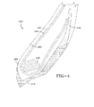
FIG. 4 is a schematic of a second embodiment of a tire bead area in accordance with the invention; and -
FIG. 5 is a stress strain diagram of the bead area ofFIG. 3 . -
FIG. 3 illustrates a bead area of atire 100 of the present invention. The tire may be a passenger tire, a truck tire, a run flat tire or pneumatic tire suitable for other applications. The tire has conventional tire components such as a ground-engaging tread (not shown) that terminates in the shoulders at the lateral edges of the tread.Sidewalls 160 extend from the shoulders and terminate in a pair ofbead portions 180, eachbead portion 180 has an annularinextensible bead core 200. Thebead cores 200 are preferably constructed of a single or monofilament steel wire continuously wrapped and a suitable bead core construction is described inUS-A- 5,263,526 . Thetire 100 has acarcass reinforcing structure 220 that extends from thefirst bead portion 180 through thefirst sidewall 160, tread,second sidewall portion 160 to thesecond bead portion 180. - The
carcass reinforcing structure 220 comprises at least one reinforcing ply. In the illustrated embodiment, there is a first radially inner reinforcingply structure 240, the ends of which are turned up around thebead cores 200, and may further include an optional second radially outer second reinforcingply structure 260, the ends of which are turned about thebead cores 200. Eachply - Located within each
bead portion 180 and the radially inner portion of thesidewall 160 is anelastomeric apex 280 disposed betweencarcass plies first carcass ply 240. Theelastomeric apex 280 extends from the radially outer side of thebead cores 200 and up into thesidewalls 160, gradually decreasing in cross-sectional width. Theapex 280 terminates prior to the maximum section width of thetire 100. - Rolling resistance is directly related to energy loss Q of each tire component. Energy loss Q is directly proportionate to G" or loss modulus, and also directly proportionate to G' or storage modulus, as represented below.

- M is the deformation index. The deformation index can be further subdivided into three pure modes of deformation:


- Thus depending upon the specific tire application, the
tire chafer 400 can be subdivided into distinct energy control, stress control and strain control zones, as shown inFIG. 3 .FIG. 5 illustrates finite element analysis of a radial medium truck tire wherein the chafer has been analyzed and the stress zones have been determined.FIG. 5 illustrates that the chafer component has three distinct zones. The tire chafer has afirst zone 410 that is the radially innermost portion of the chafer and is located radially inward of thebead core 200. This first zone is the stress control zone, and begins axially inward of the bead core, extends radially inward and under the bead core, and axially outward of the bead core terminating at a location preferably at the same radial height of the bead core. The tire chafer has asecond zone 420 that has afirst end 421 adjacent the radiallyouter end 411 of the first zone. The second zone has asecond end 422 that is radially outward of the bead about 1-2 bead diameters. Based upon the stress strain analysis, the second zone is the energy control zone. The tire chafer can be further divided into athird zone 430 that extends radially outward from the second zone to theouter tip 432 of the chafer. The third zone is representative of the strain control zone. - In each zone, the heat generation and thus the rolling resistance can be minimized by optimizing the material properties. For the stress control zone a material is selected such that the G"/G' ratio is minimized. For the energy control, G"/G' or tan delta is minimized. And for strain control, G" is minimized.
- For the chafer as shown in
FIG. 3 , thefirst zone 410 is formed of a material having a G"/G' ratio in the range of 0.2 to 0.245. Thesecond zone 420 is formed of a material having a G"/G' ratio in the range of 0.155 to 0.183. Thethird zone 430 is formed of a material having a G"/G' ratio in the range of 0.125 to 0.133.Deformation control Target G"/ G' Strain 0.125-0.133 Energy 0.155-0.183 Stress 0.200-0.245 - Unless otherwise noted, all G' values are measured on a rubber sample at a sample temperature of 90°C, at a measurement frequency of 10 Hz and at a strain amplitude of 50%. The rubber sample is taken from a cured tire manufactured to the desired manufacturer specifications. For the purposes of this invention, the storage modulus property G' is a viscoelastic property of a rubber composition and may be determined by a dynamic mechanical analyzer over a range of frequencies, temperature and strain amplitude. One example of a dynamic mechanical analyzer (DMA) suitable for measuring G', G" is model number DMA +450 sold by the 01-dB Metravib company. The DMA instrument uses dynamic mechanical analysis to evaluate rubber compositions. A cured sample of the respective rubber composition is subjected to a precisely controlled dynamic excitation (frequency and amplitude) at a frequency (Hertz) and temperature (°C) and the sample stress response is observed by the instrument. The observed sample response can be separated, by the instrument, into viscous or loss modulus (G") and elastic or storage modulus (G') components. Unless otherwise indicated, all G" are measured at the same conditions as G'.
- In order to form the chafer of multiple zones of different materials, the extruder apparati as described below may be utilized to continuously extrude a chafer having the desired material zones. A computer controller may be used to divide the chafer into a grid of small discrete annular subareas. For each discrete subarea, the desired material properties are selected. The extruder apparatus of
FIGS. 1 or2 may be used to continuously extrude a strip of a first rubber compound having the desired characteristics of zone 1. The extruder apparatus may also be used to extrude a second rubber compound having the desired characteristics of zone 2. The extruder apparatus may also be used to extrude a third rubber compound having the desired characteristics of zone 3. Thus the chafer may be divided into multiple zones, wherein each zone has a different material composition.FIG. 4 illustrates a second embodiment of the tire bead area. Everything is the same, except for the following. Thetire chafer 400 has been divided into only twozones -
FIG. 1 illustrates a first embodiment of a method andapparatus 10 for a continuous mixing system suitable for use for making rubber compositions for tires or tire components. Thecontinuous mixing system 10 is not limited to tire applications and may be used for example, to make other rubber components not related to tires such as conveyors, hoses, belts, etc. The continuous mixing system is particularly suited for making small tire components having a varying composition, such as inserts, apexes and treads (including those for retreaded tires). The mixing system may be provided directly at the tire or component building station for direct application of the rubber composition to a tire building drum or other component building apparatus. As shown inFIG. 1 , thecontinuous mixing apparatus 10 includes amain extruder 20. Themain extruder 20 has aninlet 22 for receiving one or more rubber compositions as described in more detail, below. The main extruder may comprise any commercial extruder suitable for processing of rubber or elastomer compounds. The extruder may comprise a commercially available extruder commonly known by those skilled in the art as a pin type extruder, a twin screw or a single screw extruder, or a ring type of extruder. One commercially available extruder suitable for use is a multicut transfermix (MCT) extruder, sold by VMI Holland BV, The Netherlands. Preferably, the extruder has a length to diameter ratio (L/D) of 5, but may range from 3 to 5. A ring type, pin type or MCT type of extruder is preferred, but is not limited to same. Themain extruder 20 functions to warm up the compound A to the temperature in the range of 80°C to 150°C, preferably 90 °C to 120°C, and to masticate the rubber composition as needed. - The
main extruder inlet 22 receives a first compound A, which may be a productive or non-productive rubber composition. Examples of compound A compositions are described in more detail, below. Compound A is first extruded by afirst extruder 8 and optionally a second pump 5, preferably a gear pump. Theextruder 8 may be a conventional pin type, ring type, dual screw or single screw type extruder. The pump 5 functions as a metering device and a pump and may have gears such as planetary gears, bevel gears or other gears. Theextruder 8 and gear pump 5 may also be a combination unit. Preferably, theextruder 8 has an L/D of about 3, but may range from 3 to 6. - A second compound, referred to as "compound B" also enters the
main extruder 20 at theinlet 22 and is mixed together with compound A as the compounds travel through the main extruder. Compound B may also comprise a productive or non-productive rubber composition. Examples of compound B compositions are described in more detail, below. Compound B is first extruded bysecond extruder 40 and optionally asecond pump 42, preferably a gear pump. Theextruder 40 may be a conventional pin type, ring type, dual screw or single screw type extruder. Thepump 42 functions as a metering device and a pump and may have gears such as planetary gears, bevel gears or other gears. Theextruder 40 andgear pump 42 may also be a combination unit. Preferably, theextruder 40 has an L/D of about 3, but may range from 3 to 6. - The
main extruder 20 blends compound A and compound B together in a precisely controlled amount. Oil may also be optionally injected into themain extruder 22 via anoil pump 60. The oil pump may be located at any desired location, but is preferably located at theinlet 22. The oil controls the viscosity of the compound mixture. - The
apparatus 10 may further include afirst additive pump 70 for pumping one or more additives such as a primary accelerator, which is added to the mixture at themain extruder inlet 22. The apparatus may further include a secondadditive pumping device 80 for pumping one or more additives such as a secondary accelerator into themain extruder inlet 22. The additive pumps 70, 80 may be gear pumps, gear pump extruders, Venturi pumps or other pumping means known to those skilled in the art. - If more than one accelerator is used, they may be added into the mixture separately or together. For example, a primary accelerator and a secondary accelerator may both be added. Accelerators are used to control the time and/or temperature required for vulcanization and to improve the properties of the rubber. The accelerator may be in powder form or an encapsulated powder into a resin or rubber base. Examples of accelerator compositions are described in more detail, below.
- Other additives include a curative agent or precursor, which may also be added to the mixer via
additive pump 90. One example of a curative agent is sulfur. The sulfur may be added in solid form. Theadditive pump 90 may be a gear pump, gear pump extruder combination, Venturi pump or other pumping means known to those skilled in the art. - Thus all of the constituents including compound A, compound B, sulfur, oil and any desired curative agents or precursors, or accelerators of the desired rubber composition are added to the inlet of the
main extruder 20. The main extruder blends all the constituents together and produces an output mixture of compound C which is a precise mixture of the A and B compound, optional oil the optional accelerant and optional additives. The output mixture of compound C exits the main extruder and enters anoptional gear pump 25. Theoptional gear pump 25 andmain extruder 20 is preferably located in close proximity adjacent a tire component building station ortire building station 95 for direct application onto a core, mandrel, blank or tire building drum, as shown in FIG. 6.Gear pump 25 preferably has aspecial nozzle 95 or shaping die which applies the compound formulation output from the mixer exit directly onto thetire building machine 95 in strips which are wound onto a tire building drum or core. - The ratio of the volumetric flow rate of compound A to the volumetric flow rate of compound B is precisely controlled by the ratio of the speed of the gear pump 5 for compound A and the speed of
gear pump 42 for compound B. For example, the compound output from thesystem 10 may comprise a ratio of 20% of compound A and 80% of compound B by volume. Alternatively, the compound output from the system may comprise a mixture D having a ratio of 35% of compound B and 65% of compound A by volume. Alternatively, the compound output from the system may comprise a mixture Z having a ratio of 10% of compound B and 90% of compound A by volume. The ratio of compound A to compound B can thus range from 0:100% to 100%:0. The ratio may be adjusted instantaneously by varying the speeds of gear pumps 25 and 42 by a computer controller 99. The computer controller 99 may additionally controls the extruder and gear pump operating parameters such as operating pressure, operating temperature, pump or screw speed. - Preferably, the computer controller 99 sets a pressure target value for the exit pressure of each extruder. The extruder speed is controlled by the controller, and is varied until the pressure target is met. The pressure target value affects the quality of mixing by causing backflow of the material in the extruder.
- The
system 10 of the present invention advantageously has a short residence time due to the following design features. First, all the components of compound C are added at the inlet of the main extruder. Because all the ingredients are added at the exact same location, precise formulations can be generated and controlled. Second, each extruder has a small length to diameter ratio. Third, the system is preferably located adjacent a component building station or tire building station to minimize the system line lengths in order to further reduce system residence time. -
FIG. 2 illustrates a second embodiment of the extruder apparatus of the present invention. Everything is the same as described above, except for the following. Compound A is fed into theinlet 22 of themain extruder 20. Compound B passes through anextruder 40 in combination with agear pump 42 as described above, and then is fed into the main extruder at a specific upstream location identified herein for reference purposes as "L." A primary accelerator is pumped through apumping device 70 and enters the main extruder at the same location L. An optional secondary accelerator passes through apumping device 80 and then enters themain extruder 20 at the same location L. Other additives include a curative agent or precursor, which may also be added to the mixer at location L viaadditive pump 90. Thus the addition of all the ingredients at the same extruder location allows for precise control of the compound constituents. - The following are compositions which may be used in conjunction with the invention.
- In one embodiment, a single accelerator system may be used, i.e., primary accelerator. The primary accelerator(s) may be used in total amounts ranging from 0.5 to 4, alternatively 0.8 to 1.5, phr. In another embodiment, combinations of a primary and a secondary accelerator might be used with the secondary accelerator being used in smaller amounts, such as from 0.05 to 3 phr, in order to activate and to improve the properties of the vulcanized rubber. Combinations of these accelerators might be expected to produce a synergistic effect on the final properties and are somewhat better than those produced by use of either accelerator alone. In addition, delayed action accelerators may be used which are not affected by normal processing temperatures but produce a satisfactory cure at ordinary vulcanization temperatures. Vulcanization retarders might also be used. Suitable types of accelerators that may be used in the present invention are amines, disulfides, guanidines, thioureas, thiazoles, thiurams, sulfenamides, dithiocarbamates and xanthates. In one embodiment, the primary accelerator is a sulfenamide. If a second accelerator is used, the secondary accelerator may be a guanidine, dithiocarbamate or thiuram compound. Suitable guanidines include dipheynylguanidine and the like. Suitable thiurams include tetramethylthiuram disulfide, tetraethylthiuram disulfide, and tetrabenzylthiuram disulfide.
- Representative rubbers that may be used in the rubber compound include acrylonitrile/diene copolymers, natural rubber, halogenated butyl rubber, butyl rubber, cis-1,4-polyisoprene, styrene-butadiene copolymers, cis-1,4-polybutadiene, styrene-isoprene-butadiene terpolymers ethylene-propylene terpolymers, also known as ethylene/propylene/diene monomer (EPDM), and in particular ethylene/propylene/dicyclopentadiene terpolymers. Mixtures of the above rubbers may be used. Each rubber layer may comprise of the same rubber composition or alternating layers may be of different rubber composition.
- The rubber compound may contain a platy filler. Representative examples of platy fillers include talc, clay, mica and mixture thereof. When used, the amount of platy filler ranges from 25 to 150 parts per 100 parts by weight of rubber (hereinafter referred to as phr). Preferably, the level of platy filler in the rubber compound ranges from 30 to 75 phr.
- The various rubber compositions may be compounded with conventional rubber compounding ingredients. Conventional ingredients commonly used include carbon black, silica, coupling agents, tackifier resins, processing aids, antioxidants, antiozonants, stearic acid, activators, waxes, oils, sulfur vulcanizing agents and peptizing agents. As known to those skilled in the art, depending on the desired degree of abrasion resistance, and other properties, certain additives mentioned above are commonly used in conventional amounts. Typical additions of carbon black comprise from 10 to 150 parts by weight of rubber, preferably 50 to 100 phr. Typical amounts of silica range from 10 to 250 parts by weight, preferably 30 to 80 parts by weight and blends of silica and carbon black are also included. Typical amounts of tackifier resins comprise from 2 to 10 phr. Typical amounts of processing aids comprise 1 to 5 phr. Typical amounts of antioxidants comprise 1 to 10 phr. Typical amounts of antiozonants comprise 1 to 10 phr. Typical amounts of stearic acid 0.50 to 3 phr. Typical amounts of accelerators comprise 1 to 5 phr. Typical amounts of waxes comprise 1 to 5 phr. Typical amounts of oils comprise 2 to 30 phr. Sulfur vulcanizing agents, such as elemental sulfur, amine disulfides, polymeric polysulfides, sulfur olefin adducts, and mixtures thereof, are used in an amount ranging from 0.2 to 8 phr. Typical amounts of peptizers comprise from 0.1 to 1 phr.
- The rubber composition may also include up to 70 phr of processing oil. Processing oil may be included in the rubber composition as extending oil typically used to extend elastomers. Processing oil may also be included in the rubber composition by addition of the oil directly during rubber compounding. The processing oil used may include both extending oil present in the elastomers, and process oil added during compounding. Suitable process oils include various oils as are known in the art, including aromatic, paraffinic, naphthenic, vegetable oils, and low PCA oils, such as MES, TDAE, SRAE and heavy naphthenic oils. Suitable low PCA oils include those having a polycyclic aromatic content of less than 3 percent by weight as determined by the IP346 method. Procedures for the IP346 method may be found in Standard Methods for Analysis & Testing of Petroleum and Related Products and British Standard 2000 Parts, 2003, 62nd edition, published by the Institute of Petroleum, United Kingdom.
Claims (15)
- A pneumatic tire comprising a carcass (220), the carcass (220) having one or more cord reinforced plies (240, 260) and a pair of bead portions (180) each comprising a bead core (200), wherein at least one of the bead portions (180) comprises a chafer (400) formed of at least two zones (410, 420, 430), wherein the two zones (410, 420, 430) are formed of a different material, wherein the first zone (410) extends from axially inward of the bead core (200) to an end (411) axially outward of the bead core (200), and the second zone (420) extends from the end (411) of the first zone (410) to an end (422) of the second zone (420) located radially outward of the end (411) of the first zone (410).
- The tire of claim 1 wherein the first zone (410) extends from axially inward of the bead core (200) from an axially inner end of the first zone (410) which is located radially between the radially outermost end the bead core (200) and the radially innermost end of the bead core (200).
- The tire of claim 1 or 2 wherein the end (411) of the first zone (410) located axially outward of the bead core (200) is located radially outward of the radially outermost end of the bead core (200).
- The tire of claim 1 or 2 wherein the end (411) of the first zone (410) axially outward of the bead core (200) is located radially between the radially outermost end the bead core (200) and the radially innermost end of the bead core (200).
- The tire of claim 3 wherein the end (411) of the first zone (410) axially outward of the bead core (200) is located at a distance in a range of from 0.5 to 3 times, preferably 1 to 2 times, the radial bead core diameter radially outward from the radially outermost end of the bead core (200).
- The tire of at least one of the previous claims wherein each bead portion (180) has at least one annular inextensible bead core (200) about which the cord reinforced plies (240, 260) are wrapped, and wherein the tire comprises a tread and a belt reinforcing structure disposed radially outward of the carcass.
- The tire of at least one of the previous claims wherein each bead portion (180) comprises an apex (280), preferably an at least essentially triangular shaped apex, which extends radially outward of the bead core (200).
- The tire of at least one of the previous claims wherein the second zone (420) extends from the end (411) of the first zone (410) to the radially outer end of the chafer (400).
- The tire of at least one of the claims 1 to 7 wherein the chafer (400) further comprises a third zone (430), wherein the material of the third zone (430) is different from the material of the second zone (420).
- The tire of claim 9 wherein the wherein the material of the third zone is different from the material of the second zone (420) and of the material of the first zone (410).
- The tire of claim 9 or 10 wherein the third zone (430) extends from the end radially outer end (422) of the second zone (420) to the radially outer end of the chafer (400).
- The tire of at least one of the previous claims wherein the first zone (410) is formed of a material having a G"/G' ratio in the range of from 0.2 to 0.245; and/or the second zone (420) is formed of a material having a G"/G' ratio in the range of from 0.155 to 0.183.
- The tire of at least one of the previous claims wherein the third zone (430) is formed of a material having a G"/G' ratio in the range of from 0.125 to 0.133.
- The tire of at least one of the previous claims wherein both bead portions (180) comprises said zoned chafer (400).
- The tire of at least one of the previous claims wherein only one bead portion (180) comprises said zoned chafer (400) and the other bead portion comprises a chafer having only one zone or one zone less than said zoned chafer (400).
Applications Claiming Priority (2)
| Application Number | Priority Date | Filing Date | Title |
|---|---|---|---|
| US201061426181P | 2010-12-22 | 2010-12-22 | |
| US13/095,992 US20120160392A1 (en) | 2010-12-22 | 2011-04-28 | Tire with optimized chafer |
Publications (3)
| Publication Number | Publication Date |
|---|---|
| EP2468538A2 true EP2468538A2 (en) | 2012-06-27 |
| EP2468538A3 EP2468538A3 (en) | 2012-10-17 |
| EP2468538B1 EP2468538B1 (en) | 2015-02-25 |
Family
ID=46402806
Family Applications (1)
| Application Number | Title | Priority Date | Filing Date |
|---|---|---|---|
| EP11194149.8A Active EP2468538B1 (en) | 2010-12-22 | 2011-12-16 | Tire with optimized chafer |
Country Status (4)
| Country | Link |
|---|---|
| US (1) | US20120160392A1 (en) |
| EP (1) | EP2468538B1 (en) |
| CN (1) | CN102555691B (en) |
| BR (1) | BRPI1107060A2 (en) |
Families Citing this family (3)
| Publication number | Priority date | Publication date | Assignee | Title |
|---|---|---|---|---|
| EP2878458B1 (en) | 2013-11-27 | 2018-12-26 | The Goodyear Tire & Rubber Company | Pneumatic tire |
| US10696096B2 (en) | 2015-12-08 | 2020-06-30 | The Goodyear Tire & Rubber Company | Non-pneumatic tire |
| EP3717284B1 (en) | 2017-11-30 | 2022-06-15 | Compagnie Générale des Etablissements Michelin | Pneumatic tire |
Citations (1)
| Publication number | Priority date | Publication date | Assignee | Title |
|---|---|---|---|---|
| US5263526A (en) | 1992-09-30 | 1993-11-23 | The Goodyear Tire & Rubber Company | Pneumatic tire having specified bead structure |
Family Cites Families (12)
| Publication number | Priority date | Publication date | Assignee | Title |
|---|---|---|---|---|
| JPH0253614A (en) * | 1988-08-18 | 1990-02-22 | Bridgestone Corp | Large vehicle tire |
| JPH04208443A (en) * | 1990-11-30 | 1992-07-30 | Bridgestone Corp | Pneumatic tire |
| CA2143133A1 (en) * | 1994-10-17 | 1996-04-18 | Michael Joseph Weber | Tire and vehicle system utilizing asymmetric support member molded to outer sidewall |
| JP2989750B2 (en) * | 1994-11-30 | 1999-12-13 | 住友ゴム工業株式会社 | Radial tire for high speed heavy load |
| JP3647977B2 (en) * | 1996-07-09 | 2005-05-18 | 株式会社ブリヂストン | Heavy duty pneumatic radial tire |
| JPH11301220A (en) * | 1998-04-24 | 1999-11-02 | Bridgestone Corp | Pneumatic tire for heavy load |
| JP4132542B2 (en) * | 2000-02-16 | 2008-08-13 | 住友ゴム工業株式会社 | Rubber composition for chafer and heavy duty pneumatic tire using the same |
| JP4611551B2 (en) * | 2001-03-12 | 2011-01-12 | 株式会社ブリヂストン | Unvulcanized rubber extrusion apparatus and unvulcanized rubber extrusion method |
| US20050045260A1 (en) * | 2003-08-26 | 2005-03-03 | Kiyoto Maruoka | Heavy duty tire |
| US7278455B2 (en) * | 2004-12-20 | 2007-10-09 | The Goodyear Tire & Rubber Company | Asymmetrical pneumatic run-flat tire |
| US20060185780A1 (en) * | 2005-02-18 | 2006-08-24 | The Yokohama Rubber Co., Ltd. | Pneumatic tire for passenger cars |
| US20090314408A1 (en) * | 2006-10-05 | 2009-12-24 | Takafumi Taguchi | Rubber composition for clinch apex and pneumatic tire having clinch apex using same |
-
2011
- 2011-04-28 US US13/095,992 patent/US20120160392A1/en not_active Abandoned
- 2011-12-15 BR BRPI1107060-9A patent/BRPI1107060A2/en not_active Application Discontinuation
- 2011-12-16 EP EP11194149.8A patent/EP2468538B1/en active Active
- 2011-12-22 CN CN201110435084.8A patent/CN102555691B/en not_active Expired - Fee Related
Patent Citations (1)
| Publication number | Priority date | Publication date | Assignee | Title |
|---|---|---|---|---|
| US5263526A (en) | 1992-09-30 | 1993-11-23 | The Goodyear Tire & Rubber Company | Pneumatic tire having specified bead structure |
Non-Patent Citations (1)
| Title |
|---|
| "Standard Methods for Analysis & Testing of Petroleum and Related Products and British Standard 2000 Parts", 2003, INSTITUTE OF PETROLEUM |
Also Published As
| Publication number | Publication date |
|---|---|
| CN102555691A (en) | 2012-07-11 |
| US20120160392A1 (en) | 2012-06-28 |
| EP2468538A3 (en) | 2012-10-17 |
| CN102555691B (en) | 2015-12-16 |
| BRPI1107060A2 (en) | 2013-04-16 |
| EP2468538B1 (en) | 2015-02-25 |
Similar Documents
| Publication | Publication Date | Title |
|---|---|---|
| EP2468537B1 (en) | Tire with optimized apex | |
| US9701081B2 (en) | Method for forming stratified rubber article with variable cure rate | |
| US20120161366A1 (en) | Extruder apparatus for forming tire components | |
| EP2338661B1 (en) | Method for forming a rubber article | |
| US20110146883A1 (en) | Continuous mixing system and apparatus | |
| US20110146884A1 (en) | Continuous mixing system and apparatus | |
| EP2468533B1 (en) | Pneumatic tire with composite innerliner | |
| EP2574443B1 (en) | Method for forming a tire component and pneumatic tire | |
| EP3009260A1 (en) | Pneumatic tire, and method for manufacturing pneumatic tire | |
| EP2468538B1 (en) | Tire with optimized chafer | |
| EP2468476B1 (en) | Method for forming tyre components |
Legal Events
| Date | Code | Title | Description |
|---|---|---|---|
| AK | Designated contracting states |
Kind code of ref document: A2 Designated state(s): AL AT BE BG CH CY CZ DE DK EE ES FI FR GB GR HR HU IE IS IT LI LT LU LV MC MK MT NL NO PL PT RO RS SE SI SK SM TR |
|
| AX | Request for extension of the european patent |
Extension state: BA ME |
|
| PUAI | Public reference made under article 153(3) epc to a published international application that has entered the european phase |
Free format text: ORIGINAL CODE: 0009012 |
|
| PUAL | Search report despatched |
Free format text: ORIGINAL CODE: 0009013 |
|
| AK | Designated contracting states |
Kind code of ref document: A3 Designated state(s): AL AT BE BG CH CY CZ DE DK EE ES FI FR GB GR HR HU IE IS IT LI LT LU LV MC MK MT NL NO PL PT RO RS SE SI SK SM TR |
|
| AX | Request for extension of the european patent |
Extension state: BA ME |
|
| RIC1 | Information provided on ipc code assigned before grant |
Ipc: B60C 15/06 20060101AFI20120910BHEP |
|
| 17P | Request for examination filed |
Effective date: 20130417 |
|
| 17Q | First examination report despatched |
Effective date: 20140306 |
|
| GRAP | Despatch of communication of intention to grant a patent |
Free format text: ORIGINAL CODE: EPIDOSNIGR1 |
|
| INTG | Intention to grant announced |
Effective date: 20140923 |
|
| GRAS | Grant fee paid |
Free format text: ORIGINAL CODE: EPIDOSNIGR3 |
|
| GRAA | (expected) grant |
Free format text: ORIGINAL CODE: 0009210 |
|
| AK | Designated contracting states |
Kind code of ref document: B1 Designated state(s): AL AT BE BG CH CY CZ DE DK EE ES FI FR GB GR HR HU IE IS IT LI LT LU LV MC MK MT NL NO PL PT RO RS SE SI SK SM TR |
|
| REG | Reference to a national code |
Ref country code: GB Ref legal event code: FG4D |
|
| REG | Reference to a national code |
Ref country code: CH Ref legal event code: EP |
|
| REG | Reference to a national code |
Ref country code: IE Ref legal event code: FG4D |
|
| REG | Reference to a national code |
Ref country code: DE Ref legal event code: R096 Ref document number: 602011013946 Country of ref document: DE Effective date: 20150409 |
|
| REG | Reference to a national code |
Ref country code: AT Ref legal event code: REF Ref document number: 711625 Country of ref document: AT Kind code of ref document: T Effective date: 20150415 |
|
| REG | Reference to a national code |
Ref country code: NL Ref legal event code: VDEP Effective date: 20150225 |
|
| REG | Reference to a national code |
Ref country code: AT Ref legal event code: MK05 Ref document number: 711625 Country of ref document: AT Kind code of ref document: T Effective date: 20150225 |
|
| REG | Reference to a national code |
Ref country code: LT Ref legal event code: MG4D |
|
| PG25 | Lapsed in a contracting state [announced via postgrant information from national office to epo] |
Ref country code: NO Free format text: LAPSE BECAUSE OF FAILURE TO SUBMIT A TRANSLATION OF THE DESCRIPTION OR TO PAY THE FEE WITHIN THE PRESCRIBED TIME-LIMIT Effective date: 20150525 Ref country code: FI Free format text: LAPSE BECAUSE OF FAILURE TO SUBMIT A TRANSLATION OF THE DESCRIPTION OR TO PAY THE FEE WITHIN THE PRESCRIBED TIME-LIMIT Effective date: 20150225 Ref country code: HR Free format text: LAPSE BECAUSE OF FAILURE TO SUBMIT A TRANSLATION OF THE DESCRIPTION OR TO PAY THE FEE WITHIN THE PRESCRIBED TIME-LIMIT Effective date: 20150225 Ref country code: LT Free format text: LAPSE BECAUSE OF FAILURE TO SUBMIT A TRANSLATION OF THE DESCRIPTION OR TO PAY THE FEE WITHIN THE PRESCRIBED TIME-LIMIT Effective date: 20150225 Ref country code: SE Free format text: LAPSE BECAUSE OF FAILURE TO SUBMIT A TRANSLATION OF THE DESCRIPTION OR TO PAY THE FEE WITHIN THE PRESCRIBED TIME-LIMIT Effective date: 20150225 Ref country code: ES Free format text: LAPSE BECAUSE OF FAILURE TO SUBMIT A TRANSLATION OF THE DESCRIPTION OR TO PAY THE FEE WITHIN THE PRESCRIBED TIME-LIMIT Effective date: 20150225 |
|
| PG25 | Lapsed in a contracting state [announced via postgrant information from national office to epo] |
Ref country code: LV Free format text: LAPSE BECAUSE OF FAILURE TO SUBMIT A TRANSLATION OF THE DESCRIPTION OR TO PAY THE FEE WITHIN THE PRESCRIBED TIME-LIMIT Effective date: 20150225 Ref country code: RS Free format text: LAPSE BECAUSE OF FAILURE TO SUBMIT A TRANSLATION OF THE DESCRIPTION OR TO PAY THE FEE WITHIN THE PRESCRIBED TIME-LIMIT Effective date: 20150225 Ref country code: AT Free format text: LAPSE BECAUSE OF FAILURE TO SUBMIT A TRANSLATION OF THE DESCRIPTION OR TO PAY THE FEE WITHIN THE PRESCRIBED TIME-LIMIT Effective date: 20150225 Ref country code: GR Free format text: LAPSE BECAUSE OF FAILURE TO SUBMIT A TRANSLATION OF THE DESCRIPTION OR TO PAY THE FEE WITHIN THE PRESCRIBED TIME-LIMIT Effective date: 20150526 Ref country code: IS Free format text: LAPSE BECAUSE OF FAILURE TO SUBMIT A TRANSLATION OF THE DESCRIPTION OR TO PAY THE FEE WITHIN THE PRESCRIBED TIME-LIMIT Effective date: 20150625 |
|
| PG25 | Lapsed in a contracting state [announced via postgrant information from national office to epo] |
Ref country code: NL Free format text: LAPSE BECAUSE OF FAILURE TO SUBMIT A TRANSLATION OF THE DESCRIPTION OR TO PAY THE FEE WITHIN THE PRESCRIBED TIME-LIMIT Effective date: 20150225 |
|
| PG25 | Lapsed in a contracting state [announced via postgrant information from national office to epo] |
Ref country code: CZ Free format text: LAPSE BECAUSE OF FAILURE TO SUBMIT A TRANSLATION OF THE DESCRIPTION OR TO PAY THE FEE WITHIN THE PRESCRIBED TIME-LIMIT Effective date: 20150225 Ref country code: RO Free format text: LAPSE BECAUSE OF FAILURE TO SUBMIT A TRANSLATION OF THE DESCRIPTION OR TO PAY THE FEE WITHIN THE PRESCRIBED TIME-LIMIT Effective date: 20150225 Ref country code: SK Free format text: LAPSE BECAUSE OF FAILURE TO SUBMIT A TRANSLATION OF THE DESCRIPTION OR TO PAY THE FEE WITHIN THE PRESCRIBED TIME-LIMIT Effective date: 20150225 Ref country code: EE Free format text: LAPSE BECAUSE OF FAILURE TO SUBMIT A TRANSLATION OF THE DESCRIPTION OR TO PAY THE FEE WITHIN THE PRESCRIBED TIME-LIMIT Effective date: 20150225 Ref country code: DK Free format text: LAPSE BECAUSE OF FAILURE TO SUBMIT A TRANSLATION OF THE DESCRIPTION OR TO PAY THE FEE WITHIN THE PRESCRIBED TIME-LIMIT Effective date: 20150225 |
|
| REG | Reference to a national code |
Ref country code: FR Ref legal event code: PLFP Year of fee payment: 5 |
|
| REG | Reference to a national code |
Ref country code: DE Ref legal event code: R097 Ref document number: 602011013946 Country of ref document: DE |
|
| PG25 | Lapsed in a contracting state [announced via postgrant information from national office to epo] |
Ref country code: PL Free format text: LAPSE BECAUSE OF FAILURE TO SUBMIT A TRANSLATION OF THE DESCRIPTION OR TO PAY THE FEE WITHIN THE PRESCRIBED TIME-LIMIT Effective date: 20150225 |
|
| PLBE | No opposition filed within time limit |
Free format text: ORIGINAL CODE: 0009261 |
|
| STAA | Information on the status of an ep patent application or granted ep patent |
Free format text: STATUS: NO OPPOSITION FILED WITHIN TIME LIMIT |
|
| 26N | No opposition filed |
Effective date: 20151126 |
|
| PG25 | Lapsed in a contracting state [announced via postgrant information from national office to epo] |
Ref country code: SI Free format text: LAPSE BECAUSE OF FAILURE TO SUBMIT A TRANSLATION OF THE DESCRIPTION OR TO PAY THE FEE WITHIN THE PRESCRIBED TIME-LIMIT Effective date: 20150225 |
|
| PG25 | Lapsed in a contracting state [announced via postgrant information from national office to epo] |
Ref country code: BE Free format text: LAPSE BECAUSE OF FAILURE TO SUBMIT A TRANSLATION OF THE DESCRIPTION OR TO PAY THE FEE WITHIN THE PRESCRIBED TIME-LIMIT Effective date: 20150225 |
|
| PG25 | Lapsed in a contracting state [announced via postgrant information from national office to epo] |
Ref country code: LU Free format text: LAPSE BECAUSE OF FAILURE TO SUBMIT A TRANSLATION OF THE DESCRIPTION OR TO PAY THE FEE WITHIN THE PRESCRIBED TIME-LIMIT Effective date: 20151216 Ref country code: MC Free format text: LAPSE BECAUSE OF FAILURE TO SUBMIT A TRANSLATION OF THE DESCRIPTION OR TO PAY THE FEE WITHIN THE PRESCRIBED TIME-LIMIT Effective date: 20150225 |
|
| REG | Reference to a national code |
Ref country code: CH Ref legal event code: PL |
|
| GBPC | Gb: european patent ceased through non-payment of renewal fee |
Effective date: 20151216 |
|
| REG | Reference to a national code |
Ref country code: IE Ref legal event code: MM4A |
|
| PG25 | Lapsed in a contracting state [announced via postgrant information from national office to epo] |
Ref country code: IE Free format text: LAPSE BECAUSE OF NON-PAYMENT OF DUE FEES Effective date: 20151216 Ref country code: CH Free format text: LAPSE BECAUSE OF NON-PAYMENT OF DUE FEES Effective date: 20151231 Ref country code: GB Free format text: LAPSE BECAUSE OF NON-PAYMENT OF DUE FEES Effective date: 20151216 Ref country code: LI Free format text: LAPSE BECAUSE OF NON-PAYMENT OF DUE FEES Effective date: 20151231 |
|
| REG | Reference to a national code |
Ref country code: FR Ref legal event code: PLFP Year of fee payment: 6 |
|
| PG25 | Lapsed in a contracting state [announced via postgrant information from national office to epo] |
Ref country code: SM Free format text: LAPSE BECAUSE OF FAILURE TO SUBMIT A TRANSLATION OF THE DESCRIPTION OR TO PAY THE FEE WITHIN THE PRESCRIBED TIME-LIMIT Effective date: 20150225 Ref country code: BG Free format text: LAPSE BECAUSE OF FAILURE TO SUBMIT A TRANSLATION OF THE DESCRIPTION OR TO PAY THE FEE WITHIN THE PRESCRIBED TIME-LIMIT Effective date: 20150225 Ref country code: HU Free format text: LAPSE BECAUSE OF FAILURE TO SUBMIT A TRANSLATION OF THE DESCRIPTION OR TO PAY THE FEE WITHIN THE PRESCRIBED TIME-LIMIT; INVALID AB INITIO Effective date: 20111216 |
|
| PG25 | Lapsed in a contracting state [announced via postgrant information from national office to epo] |
Ref country code: CY Free format text: LAPSE BECAUSE OF FAILURE TO SUBMIT A TRANSLATION OF THE DESCRIPTION OR TO PAY THE FEE WITHIN THE PRESCRIBED TIME-LIMIT Effective date: 20150225 |
|
| PG25 | Lapsed in a contracting state [announced via postgrant information from national office to epo] |
Ref country code: MT Free format text: LAPSE BECAUSE OF FAILURE TO SUBMIT A TRANSLATION OF THE DESCRIPTION OR TO PAY THE FEE WITHIN THE PRESCRIBED TIME-LIMIT Effective date: 20150225 Ref country code: TR Free format text: LAPSE BECAUSE OF FAILURE TO SUBMIT A TRANSLATION OF THE DESCRIPTION OR TO PAY THE FEE WITHIN THE PRESCRIBED TIME-LIMIT Effective date: 20150225 |
|
| REG | Reference to a national code |
Ref country code: FR Ref legal event code: PLFP Year of fee payment: 7 |
|
| PG25 | Lapsed in a contracting state [announced via postgrant information from national office to epo] |
Ref country code: PT Free format text: LAPSE BECAUSE OF FAILURE TO SUBMIT A TRANSLATION OF THE DESCRIPTION OR TO PAY THE FEE WITHIN THE PRESCRIBED TIME-LIMIT Effective date: 20150225 Ref country code: MK Free format text: LAPSE BECAUSE OF FAILURE TO SUBMIT A TRANSLATION OF THE DESCRIPTION OR TO PAY THE FEE WITHIN THE PRESCRIBED TIME-LIMIT Effective date: 20150225 |
|
| PG25 | Lapsed in a contracting state [announced via postgrant information from national office to epo] |
Ref country code: AL Free format text: LAPSE BECAUSE OF FAILURE TO SUBMIT A TRANSLATION OF THE DESCRIPTION OR TO PAY THE FEE WITHIN THE PRESCRIBED TIME-LIMIT Effective date: 20150225 |
|
| PGFP | Annual fee paid to national office [announced via postgrant information from national office to epo] |
Ref country code: FR Payment date: 20221010 Year of fee payment: 12 |
|
| PGFP | Annual fee paid to national office [announced via postgrant information from national office to epo] |
Ref country code: IT Payment date: 20221111 Year of fee payment: 12 Ref country code: DE Payment date: 20221018 Year of fee payment: 12 |