EP2468473A1 - Verfahren zur Herstellung eines Verbundbauteils und Verbundbauteil - Google Patents
Verfahren zur Herstellung eines Verbundbauteils und Verbundbauteil Download PDFInfo
- Publication number
- EP2468473A1 EP2468473A1 EP11010100A EP11010100A EP2468473A1 EP 2468473 A1 EP2468473 A1 EP 2468473A1 EP 11010100 A EP11010100 A EP 11010100A EP 11010100 A EP11010100 A EP 11010100A EP 2468473 A1 EP2468473 A1 EP 2468473A1
- Authority
- EP
- European Patent Office
- Prior art keywords
- plastic material
- hollow profile
- inner volume
- profile body
- hollow
- Prior art date
- Legal status (The legal status is an assumption and is not a legal conclusion. Google has not performed a legal analysis and makes no representation as to the accuracy of the status listed.)
- Withdrawn
Links
- 238000000034 method Methods 0.000 title claims abstract description 41
- 238000004519 manufacturing process Methods 0.000 title claims abstract description 15
- 239000004033 plastic Substances 0.000 claims abstract description 68
- 229920003023 plastic Polymers 0.000 claims abstract description 68
- 239000000463 material Substances 0.000 claims abstract description 65
- 239000002131 composite material Substances 0.000 claims abstract description 50
- 238000002347 injection Methods 0.000 claims abstract description 26
- 239000007924 injection Substances 0.000 claims abstract description 26
- 238000001746 injection moulding Methods 0.000 claims abstract description 22
- 230000003014 reinforcing effect Effects 0.000 claims abstract description 19
- 230000009969 flowable effect Effects 0.000 claims description 18
- 238000000465 moulding Methods 0.000 claims description 17
- XLYOFNOQVPJJNP-UHFFFAOYSA-N water Substances O XLYOFNOQVPJJNP-UHFFFAOYSA-N 0.000 claims description 15
- 238000005452 bending Methods 0.000 claims description 14
- 239000012530 fluid Substances 0.000 claims description 13
- 239000000243 solution Substances 0.000 description 5
- 239000007769 metal material Substances 0.000 description 4
- 238000006073 displacement reaction Methods 0.000 description 3
- 239000000289 melt material Substances 0.000 description 3
- 230000000694 effects Effects 0.000 description 2
- 238000007493 shaping process Methods 0.000 description 2
- 229920002430 Fibre-reinforced plastic Polymers 0.000 description 1
- 239000004952 Polyamide Substances 0.000 description 1
- 229910000831 Steel Inorganic materials 0.000 description 1
- RTAQQCXQSZGOHL-UHFFFAOYSA-N Titanium Chemical compound [Ti] RTAQQCXQSZGOHL-UHFFFAOYSA-N 0.000 description 1
- 229910052782 aluminium Inorganic materials 0.000 description 1
- XAGFODPZIPBFFR-UHFFFAOYSA-N aluminium Chemical compound [Al] XAGFODPZIPBFFR-UHFFFAOYSA-N 0.000 description 1
- 230000015572 biosynthetic process Effects 0.000 description 1
- 238000001816 cooling Methods 0.000 description 1
- 238000009826 distribution Methods 0.000 description 1
- 239000011151 fibre-reinforced plastic Substances 0.000 description 1
- 238000005429 filling process Methods 0.000 description 1
- 239000000446 fuel Substances 0.000 description 1
- 229910052751 metal Inorganic materials 0.000 description 1
- 239000002184 metal Substances 0.000 description 1
- 239000011368 organic material Substances 0.000 description 1
- 229920002647 polyamide Polymers 0.000 description 1
- 238000002360 preparation method Methods 0.000 description 1
- 230000002787 reinforcement Effects 0.000 description 1
- 229910001220 stainless steel Inorganic materials 0.000 description 1
- 239000010935 stainless steel Substances 0.000 description 1
- 239000010959 steel Substances 0.000 description 1
- 229920001169 thermoplastic Polymers 0.000 description 1
- 239000004416 thermosoftening plastic Substances 0.000 description 1
- 239000010936 titanium Substances 0.000 description 1
- 229910052719 titanium Inorganic materials 0.000 description 1
- 239000013585 weight reducing agent Substances 0.000 description 1
Images



Classifications
-
- B—PERFORMING OPERATIONS; TRANSPORTING
- B29—WORKING OF PLASTICS; WORKING OF SUBSTANCES IN A PLASTIC STATE IN GENERAL
- B29C—SHAPING OR JOINING OF PLASTICS; SHAPING OF MATERIAL IN A PLASTIC STATE, NOT OTHERWISE PROVIDED FOR; AFTER-TREATMENT OF THE SHAPED PRODUCTS, e.g. REPAIRING
- B29C45/00—Injection moulding, i.e. forcing the required volume of moulding material through a nozzle into a closed mould; Apparatus therefor
- B29C45/14—Injection moulding, i.e. forcing the required volume of moulding material through a nozzle into a closed mould; Apparatus therefor incorporating preformed parts or layers, e.g. injection moulding around inserts or for coating articles
- B29C45/14836—Preventing damage of inserts during injection, e.g. collapse of hollow inserts, breakage
-
- B—PERFORMING OPERATIONS; TRANSPORTING
- B29—WORKING OF PLASTICS; WORKING OF SUBSTANCES IN A PLASTIC STATE IN GENERAL
- B29C—SHAPING OR JOINING OF PLASTICS; SHAPING OF MATERIAL IN A PLASTIC STATE, NOT OTHERWISE PROVIDED FOR; AFTER-TREATMENT OF THE SHAPED PRODUCTS, e.g. REPAIRING
- B29C45/00—Injection moulding, i.e. forcing the required volume of moulding material through a nozzle into a closed mould; Apparatus therefor
- B29C45/14—Injection moulding, i.e. forcing the required volume of moulding material through a nozzle into a closed mould; Apparatus therefor incorporating preformed parts or layers, e.g. injection moulding around inserts or for coating articles
- B29C45/14598—Coating tubular articles
-
- B—PERFORMING OPERATIONS; TRANSPORTING
- B29—WORKING OF PLASTICS; WORKING OF SUBSTANCES IN A PLASTIC STATE IN GENERAL
- B29C—SHAPING OR JOINING OF PLASTICS; SHAPING OF MATERIAL IN A PLASTIC STATE, NOT OTHERWISE PROVIDED FOR; AFTER-TREATMENT OF THE SHAPED PRODUCTS, e.g. REPAIRING
- B29C45/00—Injection moulding, i.e. forcing the required volume of moulding material through a nozzle into a closed mould; Apparatus therefor
- B29C45/14—Injection moulding, i.e. forcing the required volume of moulding material through a nozzle into a closed mould; Apparatus therefor incorporating preformed parts or layers, e.g. injection moulding around inserts or for coating articles
- B29C45/14631—Coating reinforcements
-
- B—PERFORMING OPERATIONS; TRANSPORTING
- B62—LAND VEHICLES FOR TRAVELLING OTHERWISE THAN ON RAILS
- B62D—MOTOR VEHICLES; TRAILERS
- B62D29/00—Superstructures, understructures, or sub-units thereof, characterised by the material thereof
- B62D29/001—Superstructures, understructures, or sub-units thereof, characterised by the material thereof characterised by combining metal and synthetic material
- B62D29/004—Superstructures, understructures, or sub-units thereof, characterised by the material thereof characterised by combining metal and synthetic material the metal being over-moulded by the synthetic material, e.g. in a mould
-
- B—PERFORMING OPERATIONS; TRANSPORTING
- B29—WORKING OF PLASTICS; WORKING OF SUBSTANCES IN A PLASTIC STATE IN GENERAL
- B29C—SHAPING OR JOINING OF PLASTICS; SHAPING OF MATERIAL IN A PLASTIC STATE, NOT OTHERWISE PROVIDED FOR; AFTER-TREATMENT OF THE SHAPED PRODUCTS, e.g. REPAIRING
- B29C45/00—Injection moulding, i.e. forcing the required volume of moulding material through a nozzle into a closed mould; Apparatus therefor
- B29C45/14—Injection moulding, i.e. forcing the required volume of moulding material through a nozzle into a closed mould; Apparatus therefor incorporating preformed parts or layers, e.g. injection moulding around inserts or for coating articles
- B29C45/14778—Injection moulding, i.e. forcing the required volume of moulding material through a nozzle into a closed mould; Apparatus therefor incorporating preformed parts or layers, e.g. injection moulding around inserts or for coating articles the article consisting of a material with particular properties, e.g. porous, brittle
- B29C45/14786—Fibrous material or fibre containing material, e.g. fibre mats or fibre reinforced material
-
- B—PERFORMING OPERATIONS; TRANSPORTING
- B29—WORKING OF PLASTICS; WORKING OF SUBSTANCES IN A PLASTIC STATE IN GENERAL
- B29C—SHAPING OR JOINING OF PLASTICS; SHAPING OF MATERIAL IN A PLASTIC STATE, NOT OTHERWISE PROVIDED FOR; AFTER-TREATMENT OF THE SHAPED PRODUCTS, e.g. REPAIRING
- B29C45/00—Injection moulding, i.e. forcing the required volume of moulding material through a nozzle into a closed mould; Apparatus therefor
- B29C45/14—Injection moulding, i.e. forcing the required volume of moulding material through a nozzle into a closed mould; Apparatus therefor incorporating preformed parts or layers, e.g. injection moulding around inserts or for coating articles
- B29C45/14819—Injection moulding, i.e. forcing the required volume of moulding material through a nozzle into a closed mould; Apparatus therefor incorporating preformed parts or layers, e.g. injection moulding around inserts or for coating articles the inserts being completely encapsulated
-
- B—PERFORMING OPERATIONS; TRANSPORTING
- B29—WORKING OF PLASTICS; WORKING OF SUBSTANCES IN A PLASTIC STATE IN GENERAL
- B29K—INDEXING SCHEME ASSOCIATED WITH SUBCLASSES B29B, B29C OR B29D, RELATING TO MOULDING MATERIALS OR TO MATERIALS FOR MOULDS, REINFORCEMENTS, FILLERS OR PREFORMED PARTS, e.g. INSERTS
- B29K2105/00—Condition, form or state of moulded material or of the material to be shaped
- B29K2105/06—Condition, form or state of moulded material or of the material to be shaped containing reinforcements, fillers or inserts
- B29K2105/20—Inserts
-
- B—PERFORMING OPERATIONS; TRANSPORTING
- B29—WORKING OF PLASTICS; WORKING OF SUBSTANCES IN A PLASTIC STATE IN GENERAL
- B29L—INDEXING SCHEME ASSOCIATED WITH SUBCLASS B29C, RELATING TO PARTICULAR ARTICLES
- B29L2031/00—Other particular articles
- B29L2031/30—Vehicles, e.g. ships or aircraft, or body parts thereof
-
- B—PERFORMING OPERATIONS; TRANSPORTING
- B29—WORKING OF PLASTICS; WORKING OF SUBSTANCES IN A PLASTIC STATE IN GENERAL
- B29L—INDEXING SCHEME ASSOCIATED WITH SUBCLASS B29C, RELATING TO PARTICULAR ARTICLES
- B29L2031/00—Other particular articles
- B29L2031/30—Vehicles, e.g. ships or aircraft, or body parts thereof
- B29L2031/3002—Superstructures characterized by combining metal and plastics, i.e. hybrid parts
Definitions
- the present invention relates to a method for producing a composite component, which is reinforced by a hollow profile body, and a composite component which can be produced by this method.
- composite components or hybrid components which are reinforced by a hollow profile body, which usually consists of a metallic material. It is also known to provide front end support made of polyamide for reinforcement with metal inserts or so-called.
- Hydroforming profiles the latter by the known hydroforming (abbr. IHU) are shaped profiles, which may have local openings to injections in the manufacture of the to realize respective composite component.
- the wall of the reinforcing provided for profile hollow body has a certain minimum thickness or minimum thickness, so that the hollow profile body as a result of the resulting injection molding melt pressure or plastic material Print not deformed or deformed.
- the provision of a certain minimum thickness or minimum thickness of the profiled hollow body has the consequence that a certain weight of the hollow profile body may not be exceeded in order to avoid a deformation or deformation of the hollow profile body caused by the manufacturing process.
- the present invention has for its object to provide a method for producing a reinforced by a hollow profile member composite component and a producible by this method composite component, wherein in the process of the hollow profile body compared to hollow profile members of known composite components may be formed substantially thin-walled without that during manufacture Deformation or deformation of the hollow profile body occurs.
- This object is achieved with a method for producing a composite component having the features of claim 1 and with a composite component having the features of claim 15.
- step (c) of the method according to the invention the profile hollow body is supported during injection by a reinforcing medium in the inner volume of the profiled hollow body or in the interior of the hollow profile body.
- the reinforcing medium By providing the reinforcing medium, during the injection of the plastic material, which is preferably a thermoplastic, deformation or deformation of the hollow profile body due to a pressure of the flowable plastic material or plastic melt material acting on the profile hollow body in the cavity can be avoided.
- a hollow profile body can be provided, which can be designed to be much thinner compared to hollow profile members of known composite components without deformation or deformation of the hollow profile body occurring during production or that a local opening of the hollow profile body would be required.
- the compared to known composite components much thinner walled design of the hollow profile body has the consequence that the composite components, in contrast to comparable known solutions have a much lower weight.
- This reduction in weight is particularly in composite components or hybrid components that are used as a component of a motor vehicle - such.
- a composite component in the form of a bending beam - is advantageous because reduced in particular the fuel consumption or the axle load distribution can be optimized with the weight reduction.
- the provision of a profiled hollow body provides a composite component with a high strength and a high rigidity, in particular a high torsional rigidity, and at the same time with a high degree of design freedom in the design or shaping of the composite component.
- an incompressible fluid is particularly preferably used.
- the internal volume can be filled or filled with the incompressible fluid to reinforce the hollow profile body, so that it is completely or at least substantially completely filled with the incompressible fluid.
- Compressible components in particular air, are completely or almost completely removed by filling the inner volume or the interior of the hollow profile body with the incompressible fluid, so that deformation or deformation of the hollow profile body during injection as a result of acting in the cavity on the hollow profile body Pressure of the flowable plastic material or plastic melt material can be very effectively avoided.
- the incompressible fluid is preferably water, which can be taken inexpensively conventional water supply lines.
- the profiled hollow body provided in step (a) preferably has a wall with a maximum wall thickness which is within a range of 0.3 mm to 3 mm.
- the hollow profile body is preferably made of a metallic material, wherein the metallic material is or comprises preferably aluminum or steel, more preferably stainless steel or titanium.
- the hollow profile body can also consist of an organic material - for example, fiber-reinforced plastic material.
- the profiled hollow body provided in step (a) may have an outer circumference varying in the longitudinal direction of the profiled hollow body.
- the outer circumference can be stepped, continuous, discontinuous or vary in a combination of the aforementioned possibilities.
- the profiled hollow body provided in step (a) may have a cross-sectional geometry varying in the longitudinal direction of the profiled hollow body.
- the cross-sectional geometry can thereby vary circular, rectangular, polygonal, triangular, elliptical or in a combination of the aforementioned possibilities.
- the inner volume of the hollow profile body is filled with the reinforcing medium, the inner volume is subsequently closed, and the reinforcing medium is removed from the inner volume after step (d).
- the inner volume is preferably closed by at least one stopper, and the hollow profile body is introduced into the cavity with the stopper in step (b), wherein over the stopper a pressure on the reinforcing medium in the cavity which builds up during the injection of the plastic material in the cavity Internal volume is transferable.
- the reinforcing medium is preferably an incompressible fluid, in particular water, which is removed from the internal volume after curing in step (d) and which, as stated above, due to the displacement of compressible portions by the filling or filling of the internal volume with the incompressible fluid deformations or deformations of the hollow profile body during molding according to step (c) of the inventive method effectively avoids.
- the inner volume is preferably closed by at least one stopper, and the hollow profile body is introduced into the cavity with the stopper in step (b), wherein a pressure on the reinforcing medium in the cavity building up upon injection of the plastic material in the cavity is provided via the stopper Internal volume is transferable.
- the pressure transfer of the pressure building up in the cavity ie in particular the pressure of the injected flowable plastic material or the injected plastic material melt onto the reinforcing medium, which is in particular in the form of an incompressible fluid, can be achieved despite thorough filling of the internal volume with the fluid existing compressible components or media in the fluid, so in particular air pockets or air bubbles are reduced by the pressure transfer in size so far that of these no or no significant deforming or deforming effect on the hollow profile body during molding in step (c) can go out ,
- the inner volume of the hollow profile body is filled with the gain medium and the gain medium is removed from the inner volume after step (d), wherein in this further practical embodiment the Reinforcing medium particularly preferably an incompressible fluid, in particular water.
- the filling of the inner volume takes place in this further practical embodiment so after the hollow profile body was introduced into the cavity of the injection molding tool, which is particularly advantageous for the production of a plurality of identical composite components, in particular because the filling in the cavity erflogt and therefore to be provided for the filling Process time can be set very short.
- the fluid may in this further practical embodiment be e.g. in a practical manner via at least one feed channel of the injection molding tool, which extends to the interior or the internal volume of the hollow profile body, are supplied to the inner volume.
- the gain medium is displaced by introducing air from the inner volume, so that therefore takes place a removal of the gain medium from the inner volume by displacement by means of embedded air.
- Air as a displacement medium in particular in the form of compressed air, can be provided in a practical manner by conventional compressors or pressure vessels.
- a part of the injected plastic material is used as the reinforcing medium, the inner volume of the hollow profile body being splashed with this plastic material during the molding of the composite component in step (c).
- the plastic material injected into the inner volume serves as a reinforcing medium which is injected into the inner volume or the interior of the profiled hollow body during the molding or injection molding of the composite component. Also by means of this preferred embodiment can be effectively avoided deformation or deformation of the hollow profile body during molding in step (c). Due to the fact that the flowable plastic material is also injected into the interior volume or the interior of the hollow profile body during molding, substantially equal pressures are built up in the interior volume and in the region of the cavity in the vicinity of the hollow profile body, accompanied by effective avoidance of a Deformation or deformation of the hollow profile body.
- the plastic material injected into the internal volume is preferably removed from the internal volume after step (c) so that in step (d) of the method according to the invention only the plastic material surrounding the profile hollow body and forming the shape of the composite component is cured.
- the removal of the injected plastic material is particularly advantageous if in the cross-section of the hollow profile body, the cross-sectional area of the inner volume is comparatively large, ie in particular greater than 15 to 400 mm 2 , so that the removal of the plastic material serves to provide a lightweight composite component.
- the injected into the internal volume plastic material may also remain in the internal volume and cured.
- the cross-sectional area of the inner volume is comparatively small, that is, in particular less than 1 to 15 mm 2 .
- the increase in weight caused by the plastic material remaining in the inner volume is not so significant.
- the remaining plastic material additionally reinforces the composite component and eliminates the removal of the plastic material, along with an advantageous substantial reduction of the production effort.
- step (d) and before the plastic material injected into the internal volume has completely cured, the internal volume of remaining flowable plastic material is only partially freed, with the interior volume of remaining flowable plastic material being particularly freed as soon as possible At least partially a layer of cured plastic material has formed on the inside of the wall of the hollow profile body limiting the internal volume.
- a profile reinforcing body and thus also the composite component reinforcing layer is particularly advantageously formed on the inside of the wall of the hollow profile body bounding the inner volume, accompanied by the creation of a particularly stable composite component.
- the inner volume of the remaining flowable plastic material is not released until the layer has a minimum thickness which is within a range of half to ten times the minimum wall thickness of the wall.
- the composite component which can be produced by the method according to the invention is reinforced by a hollow profile body, the hollow profile body having a wall with a maximum wall thickness which is within a range of 0.1 mm to 3 mm, preferably 0.2 mm to 2 mm, more preferably 0, 3 mm to 1 mm.
- the hollow profile body has a wall with a maximum wall thickness, which is formed substantially smaller than in known solutions, so that the producible by the process according to the invention composite component in comparison to comparable known solutions significantly lower weight and further by the Hollow profile caused high rigidity and strength.
- the composite component can in particular be an instrument panel of a motor vehicle or a bending support for the front area or the rear area of a motor vehicle.
- the composite component may also be a front end support for a motor vehicle or a stiffening element for the tailgate of a motor vehicle or an A-pillar or a B-pillar of the body of a motor vehicle.
- Fig. 1 schematically illustrated, produced by the inventive method composite component 10 is formed in the form of a bending beam 10 for a motor vehicle and is by a tubular profile hollow body 12 (see also Fig. 2 ) reinforced from a metallic material.
- the hollow profile body 12 has as a hollow body a closed cross-sectional profile (not shown in detail here).
- the profile hollow bodies of known bending beams of the hollow profile body 12 may be formed substantially thin-walled, since in a production of this composite component by the inventive method, deformation or deformation of the hollow profile body 12 is effectively avoided.
- the wall thickness of the hollow profile body of this embodiment is 0.5 mm. Typical wall thicknesses of the hollow profile body 12 are in the range of 0.1 mm to 3 mm.
- the Fig. 3 shows a schematic sectional view of an injection molding tool 14 with a cavity 16 for molding a composite component in the form of a bending beam.
- the injection molding tool 14 has two injection channels 18 for injecting flowable plastic material and a supply channel 20 for supplying water as a gain medium.
- the Fig. 4 shows a schematic sectional view of one end of a hollow profile body 12 with a plug attached to the end 22.
- Die Fig. 5 shows a schematic sectional view of a second injection molding tool 14, said injection molding tool 14 has a cavity 16 for molding a composite component in the form of a bending beam, in which a hollow profile body 12 is introduced.
- 4 and 5 serve to illustrate a first embodiment of the method according to the invention in which, inter alia before step (b) - ie before introducing the profiled hollow body 12 in the cavity 16 of the injection mold 14 - the inner volume 24 of the hollow profile body 12 with water 26 (illustrated in the figures by dots ) filled as a gain medium and the inner volume 24 is then closed.
- the water 26 can in this case be supplied from a filling station (not shown).
- FIG. 4 illustrated closing with the plug 22, which closes the only open end of the tubular hollow profile body 12.
- Fig. 5 illustrates the situation after the introduction of the filled with water 26 and sealed by the plug 22 profile hollow body 12 in the cavity 16 of the injection mold 14 and during the molding of the bending beam by injecting flowable plastic material in the cavity 16 via three injection channels 18 (symbolically through the three Arrows illustrated).
- injection molding tool 14 has the cavity 16 of in Fig. 5 injection molding tool 14 shown on a further Kavticians Scheme 28 for arranging the plug 22, which is over-injected or molded according to the illustrated here first embodiment of the method according to the invention of the flowable plastic material.
- a pressure which builds up on the water 26 in the inner volume 24 during the injection of the plastic material in the cavity 16 can be transferred, in order, if necessary, despite careful filling of the inner volume 24 with the water 26, remaining compressible air inclusions or air bubbles through the pressure transfer in reduce their size, so that of these no or no significant deforming or deforming effect on the hollow profile body 12 during molding according to the inventive step (c) can go out.
- the water 26 is removed from the inner volume 24 after removal of the plug 22.
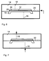
- the 6 and 7 show further schematic sectional views of the in Fig. 3 illustrated injection molding tool 14 each together with a arranged in the cavity 16 hollow profile body 12 for illustrating a second embodiment of the method according to the invention.
- the inner volume 24 of the hollow profile body 12 via the feed channel 20 is filled with water 26, as in Fig. 6 illustrated in which the filling of the inner volume 24 with water 26 is illustrated by an arrow.
- the arrows of the Fig. 7 illustrate the forming of the bending beam by injecting flowable plastic material into the cavity 16 via the two injection channels 18.
- the injected plastic material is cured and the water 26 is removed from the interior volume 24 after curing by introduction of compressed air.
- the Fig. 8 shows a schematic sectional view of a third injection molding tool 14 together with a profile hollow body 12 arranged in the cavity 16 to illustrate a third embodiment of the method according to the invention, wherein the in Fig. 8 shown injection molding tool 14 has three injection channels 18.
- a part of the injected plastic material is used as the reinforcing medium 26, wherein the inner volume 24 of the hollow profile body 12 with this plastic material 26 during the injection of the plastic material into the cavity 16 - that is injected during the molding of the bending beam.
- the shaping of the bending support which takes place at the same time or substantially simultaneously with the full injection of the inner volume 24, is indicated by corresponding arrows (in FIG Fig. 8 shown above and below) illustrating injection of plastic material into the cavity 16 via two of the three injection channels 18.
- the right outer arrow illustrates the full injection of the inner volume 24 via the third injection channel 18.
- the inner volume 24 is partially freed in accordance with this third embodiment during curing according to the inventive step (d) and before the injected into the inner volume 24 gain medium 26 in the form of the plastic material is completely freed of remaining flowable plastic material, so that, as Fig. 9 illustrates after this liberating or removing the remaining flowable plastic material at the inner volume 24 bounding inside 30 of Wall 32 of the hollow profile body 12 remains a layer 34 of cured plastic material.
- the formation of such a layer 34 is possible because during curing or cooling, inner regions of the plastic material injected into the inner volume 24 cool or harden more slowly than outer regions of the plastic material injected into the inner volume 24.
- the inner volume 24 of the hollow profile body 12 is thus freed of the remaining flowable plastic material within the inner volume 24 as soon as the layer 34 has a minimum thickness, which may in particular be within a range of half to ten times the minimum wall thickness of the wall 32.
Landscapes
- Engineering & Computer Science (AREA)
- Mechanical Engineering (AREA)
- Manufacturing & Machinery (AREA)
- Architecture (AREA)
- Structural Engineering (AREA)
- Chemical & Material Sciences (AREA)
- Combustion & Propulsion (AREA)
- Transportation (AREA)
- Injection Moulding Of Plastics Or The Like (AREA)
Abstract
Die Erfindung betrifft ein Verfahren zur Herstellung eines Verbundbauteils (10), das durch einen Profilhohlkörper (12) verstärkt ist, wobei das Verfahren die folgenden Schritte umfasst:
(a) Bereitstellen eines Profilhohlkörpers (12),
(b) Einbringen des Profilhohlkörpers (12) in eine Kavität (16) eines Spritzgusswerkzeugs (14),
(c) Formen des Verbundbauteils (10) durch Einspritzen von Kunststoffmaterial in die Kavität (16), wobei der Profilhohlkörper (12) während des Einspritzens durch ein Verstärkungsmedium (26) im Innenvolumen (24) des Profihohlkörpers (12) gestützt wird, und
(d) Aushärten des eingespritzten Kunststoffmaterials.
(a) Bereitstellen eines Profilhohlkörpers (12),
(b) Einbringen des Profilhohlkörpers (12) in eine Kavität (16) eines Spritzgusswerkzeugs (14),
(c) Formen des Verbundbauteils (10) durch Einspritzen von Kunststoffmaterial in die Kavität (16), wobei der Profilhohlkörper (12) während des Einspritzens durch ein Verstärkungsmedium (26) im Innenvolumen (24) des Profihohlkörpers (12) gestützt wird, und
(d) Aushärten des eingespritzten Kunststoffmaterials.
Die Erfindung betrifft ferner ein nach diesem Verfahren herstellbares Verbundbauteil.
Description
- Die vorliegende Erfindung betrifft ein Verfahren zur Herstellung eines Verbundbauteils, das durch einen Profilhohlkörper verstärkt ist, und ein nach diesem Verfahren herstellbares Verbundbauteil.
- Insbesondere im Automobilbereich gibt es Verbundbauteile bzw. Hybridbauteile, welche durch einen Profilhohlkörper, der meist aus einem metallischen Material besteht, verstärkt sind. Es ist auch bekannt, Frontendträger aus Polyamid zur Verstärkung mit Blecheinlegern oder sog. IHU-Profilen zu versehen, wobei letztere durch die bekannte Innenhochdruck-Umformung (Abk. IHU) geformte Profile sind, welche lokale Öffnungen aufweisen können, um Durchspritzungen bei der Herstellung des jeweiligen Verbundbauteils zu realisieren. Bei den bekannten Verfahren zur Herstellung der Verbundbauteile wird der Profilhohlkörper - nachdem er in eine formgebende Kavität eines Spritzgusswerkzeugs gelegt worden ist - von fließfähigem Kunststoffmaterial umspritzt. Infolge des beim Einspritzen des Kunststoffmaterials bzw. der Kunststoffschmelze entstehenden Schmelzedrucks bzw. Kunststoffmaterial-Drucks ist es erforderlich, dass die Wandung der zur Verstärkung vorgesehenen Profilhohlkörper eine bestimmte Mindeststärke bzw. Mindestdicke aufweist, damit sich der Profilhohlkörper infolge des beim Spritzgießen entstehenden Schmelzedrucks bzw. Kunststoffmaterial-Drucks nicht deformiert bzw. verformt. Das Vorsehen einer bestimmten Mindeststärke bzw. Mindestdicke des Profihohlkörpers hat zur Folge, dass ein bestimmtes Gewicht des Profilhohlkörpers nicht unterschritten werden darf, um eine durch das Herstellungsverfahren verursachte Verformung bzw. Deformation des Profilhohlkörpers zu vermeiden.
- Der vorliegenden Erfindung liegt die Aufgabe zugrunde, ein Verfahren zur Herstellung eines durch einen Profilhohlkörper verstärkten Verbundbauteils und ein durch dieses Verfahren herstellbares Verbundbauteil anzugeben, wobei bei dem Verfahren der Profilhohlkörper im Vergleich zu Profilhohlkörpern bekannter Verbundbauteile wesentlich dünnwandiger ausgebildet sein kann ohne dass bei der Herstellung eine Deformation oder Verformung des Profilhohlkörpers auftritt.
- Diese Aufgabe wird erfindungsgemäß mit einem Verfahren zur Herstellung eines Verbundbauteils mit den Merkmalen des Anspruchs 1 und mit einem Verbundbauteil mit den Merkmalen des Anspruchs 15 gelöst.
- Das erfindungsgemäße Verfahren zur Herstellung eines Verbundbauteils, das durch einen Profilhohlkörper verstärkt ist, umfasst die folgenden Schritte:
- (a) Bereitstellen eines Profilhohlkörpers,
- (b) Einbringen des Profilhohlkörpers in eine Kavität eines Spritzgusswerkzeugs,
- (c) Formen des Verbundbauteils durch Einspritzen von Kunststoffmaterial in die Kavität, wobei der Profilhohlkörper während des Einspritzens durch ein Verstärkungsmedium im Innenvolumen des Profihohlkörpers gestützt wird, und
- (d) Aushärten des eingespritzten Kunststoffmaterials.
- In Schritt (c) des erfindungsgemäßen Verfahrens wird der Profilhohlkörper während des Einspritzens durch ein Verstärkungsmedium im Innenvolumen des Profihohlkörpers bzw. im Inneren des Profilhohlkörpers gestützt.
- Durch Vorsehen des Verstärkungsmediums kann während des Einspritzens des Kunststoffmaterials, welches bevorzugt ein Thermoplast ist, eine Deformation bzw. Verformung des Profilhohlkörpers infolge eines in der Kavität auf den Profilhohlkörper einwirkenden Drucks des fließfähigen Kunststoffmaterials bzw. der Kunststoffmaterialschmelze vermieden werden. Dies hat den Vorteil, dass zur Herstellung des Verbundbauteils in Schritt (a) des erfindungsgemäßen Verfahrens ein Profilhohlkörper bereitgestellt werden kann, der im Vergleich zu Profilhohlkörpern bekannter Verbundbauteile wesentlich dünnwandiger ausgebildet sein kann ohne, dass bei der Herstellung eine Deformation oder Verformung des Profilhohlkörpers auftreten kann oder dass ein lokales Öffnen des Profilhohlkörpers erforderlich wäre.
- Die gegenüber bekannten Verbundbauteilen wesentlich dünnwandigere Ausbildung des Profilhohlkörpers hat zur Folge, dass die Verbundbauteile im Unterschied zu vergleichbaren bekannten Lösungen ein wesentlich geringeres Gewicht aufweisen. Diese Reduzierung des Gewichts ist insbesondere bei Verbundbauteilen bzw. Hybridbauteilen, die als Bauteil eines Kraftfahrzeugs verwendet werden - wie z. B. ein Verbundbauteil in Form eines Biegeträgers - von Vorteil, da mit der Gewichtsreduzierung insbesondere auch der Treibstoffverbrauch reduziert oder die Achslastverteilung optimiert werden kann. Ferner wird durch das Vorsehen eines Profilhohlkörpers ein Verbundbauteil mit einer hohen Festigkeit und einer hohen Steifigkeit, insbesondere einer hohen Torsionssteifigkeit bereitgestellt, und zwar bei gleichzeitig hoher Gestaltungsfreiheit bei der Gestaltung bzw. Formung des Verbundbauteils.
- Als Verstärkungsmedium wird besonders bevorzugt ein inkompressibles Fluid verwendet. Das Innenvolumen kann zur Verstärkung des Profilhohlkörpers mit dem inkompressiblen Fluid aufgefüllt bzw. gefüllt werden, so dass es also vollständig bzw. zumindest im wesentlichen vollständig mit dem inkompressiblen Fluid gefüllt ist. Kompressible Anteile, insbesondere Luft, werden durch das Füllen des Innenvolumens bzw. des Inneren des Profilhohlkörpers mit dem inkompressiblen Fluid vollständig bzw. nahezu vollständig entfernt, so dass eine Deformation bzw. Verformung des Profilhohlkörpers während des Einspritzens infolge des in der Kavität auf den Profilhohlkörper einwirkenden Drucks des fließfähigen Kunststoffmaterials bzw. der Kunststoffmaterialschmelze sehr wirksam vermieden werden kann. Das inkompressible Fluid ist vorzugsweise Wasser, welches kostengünstig üblichen Wasserversorgungsleitungen entnommen werden kann.
- Der in Schritt (a) bereitgestellte Profilhohlkörper weist vorzugsweise eine Wandung mit einer maximalen Wandstärke auf, die innerhalb eines Bereichs von 0,3 mm bis 3 mm liegt. Der Profilhohlkörper besteht vorzugsweise aus einem metallischen Material, wobei das metallische Material vorzugsweise Aluminium oder Stahl, weiter vorzugsweise rostfreier Stahl oder Titan ist oder umfasst. Der Profilhohlkörper kann jedoch auch aus einem organischen Material bestehen - beispielsweise aus faserverstärktem Kunststoffmaterial.
- Der in Schritt (a) bereitgestellte Profilhohlkörper kann einen in Längsrichtung des Profilhohlkörpers variierenden Außenumfang aufweisen. Der Außenumfang kann dabei gestuft, kontinuierlich, diskontinuierlich oder in einer Kombination der vorgenannten Möglichkeiten variieren.
- Der in Schritt (a) bereitgestellte Profilhohlkörper kann eine in Längsrichtung des Profilhohlkörpers variierende Querschnittsgeometrie aufweisen. Die Querschnittsgeometrie kann dabei kreisförmig, rechteckig, vieleckig, dreieckig, elliptisch oder in einer Kombination der vorgenannten Möglichkeiten variieren.
- Da, wie oben dargelegt, eine Deformation bzw. Verformung des Profilhohlkörpers während des Einspritzens - infolge des in der Kavität auf den Profilhohlkörper einwirkenden Drucks des fließfähigen Kunststoffmaterials bzw. der Kunststoffmaterialschmelze - bei der Herstellung mittels des erfindungsgemäßen Verfahrens sehr wirksam vermieden werden kann, ist es möglich Verbundbauteile mit Profilhohlkörpern herzustellen, welche die obigen geringen maximalen Wandstärken aufweisen, einhergehend mit einer wesentlichen Reduzierung des Gewichts im Vergleich zu bekannten Lösungen.
- Bei einer praktischen Ausführungsform des erfindungsgemäßen Verfahrens wird vor Schritt (b) das Innenvolumen des Profilhohlkörpers mit dem Verstärkungsmedium aufgefüllt, das Innenvolumen anschließend verschlossen, und das Verstärkungsmedium nach Schritt (d) aus dem Innenvolumen entfernt. Bei dieser praktischen Ausführungsform wird das Innenvolumen vorzugsweise durch wenigstens einen Stopfen verschlossen, und der Profilhohlkörper wird in Schritt (b) mit dem Stopfen in die Kavität eingebracht, wobei über den Stopfen ein sich beim Einspritzen des Kunststoffmaterials in der Kavität aufbauender Druck auf das Verstärkungsmedium im Innenvolumen übertragbar ist.
- Dadurch, dass das Innenvolumen des Profilhohlkörpers vor dem Einbringen des Profilhohlkörpers in die Kavität des Spritzgusswerkzeugs mit dem Verstärkungsmedium aufgefüllt und auch vor diesem Einbringen das Innenvolumen anschließend verschlossen wird, wird der Profilhohlkörper bereits außerhalb der Kavität auf das Formen gemäß Schritt (c) des erfindungsgemäßen Verfahrens vorbereitet. Bei dieser praktischen Ausführungsform ist das Verstärkungsmedium vorzugsweise ein inkompressibles Fluid, insbesondere Wasser, welches nach dem Aushärten in Schritt (d) aus dem Innenvolumen entfernt wird und welches, wie bereits oben dargelegt, infolge der Verdrängung kompressibler Anteile durch das Füllen bzw. Auffüllen des Innenvolumens mit dem inkompressiblen Fluid Deformationen bzw. Verformungen des Profilhohlkörpers während des Formens gemäß Schritt (c) des erfindungsgemäßen Verfahrens wirksam vermeidet.
- Das Innenvolumen wird bei dieser praktischen Ausführungsform vorzugsweise durch wenigstens einen Stopfen verschlossen, und der Profilhohlkörper wird in Schritt (b) mit dem Stopfen in die Kavität eingebracht, wobei über den Stopfen ein sich beim Einspritzen des Kunststoffmaterials in der Kavität aufbauender Druck auf das Verstärkungsmedium im Innenvolumen übertragbar ist.
- Durch die über den wenigstens einen Stopfen ermöglichte Druckübertragung des sich in der Kavität aufbauenden Drucks - also insbesondere des Drucks des eingespritzten fließfähigen Kunststoffmaterials bzw. der eingespritzten Kunststoffmaterialschmelze - auf das insbesondere in Form eines inkompressiblen Fluids ausgebildete Verstärkungsmedium können trotz sorgfältigen Auffüllens des Innenvolumens mit dem Fluid noch bestehende kompressible Anteile bzw. Medien im Fluid, also insbesondere Lufteinschlüsse bzw. Luftblasen durch die Druckübertagung in ihrer Größe soweit reduziert werden, dass von diesen keine oder keine wesentliche deformierende oder verformende Wirkung auf den Profilhohlkörper während des Formens in Schritt (c) ausgehen kann.
- Bei einer weiteren praktischen Ausführungsform des erfindungsgemäßen Verfahrens wird nach Schritt (b) und vor Schritt (c) das Innenvolumen des Profilhohlkörpers mit dem Verstärkungsmedium aufgefüllt und das Verstärkungsmedium wird nach Schritt (d) aus dem Innenvolumen entfernt, wobei auch bei dieser weiteren praktischen Ausführungsform das Verstärkungsmedium besonders bevorzugt ein inkompressibles Fluid, insbesondere Wasser ist.
- Die Auffüllung des Innenvolumens erfolgt bei dieser weiteren praktischen Ausführungsform also nachdem der Profilhohlkörper in die Kavität des Spritzgusswerkzeugs eingebracht wurde, was insbesondere für die Herstellung einer Vielzahl baugleicher Verbundbauteile von Vorteil ist, insbesondere weil das Auffüllen in der Kavität erflogt und daher die für das Füllen bereitzustellende Prozesszeit sehr kurz eingerichtet werden kann. Das Fluid kann bei dieser weiteren praktischen Ausführungsform z.B. auf praktische Weise über wenigstens einen Zuführkanal des Spritzgusswerkzeugs, der sich bis zu dem Inneren bzw. dem Innenvolumen des Profilhohlkörpers erstreckt, dem Innenvolumen zugeführt werden.
- Bevorzugt wird das Verstärkungsmedium durch Einbringen von Luft aus dem Innenvolumen verdrängt, so dass also eine Entfernung des Verstärkungsmediums aus dem Innenvolumen durch Verdrängen mittels eingebachter Luft erfolgt. Luft als Verdrängungsmedium, insbesondere in Form von Druckluft, kann auf praktische Weise von üblichen Kompressoren oder Druckbehälter bereitgestellt werden.
- Bei einer bevorzugten Ausführungsform des erfindungsgemäßen Verfahrens wird als Verstärkungsmedium ein Teil des eingespritzten Kunststoffmaterials verwendet, wobei das Innenvolumen des Profilhohlkörpers mit diesem Kunststoffmaterial während des Formens des Verbundbauteils in Schritt (c) vollgespritzt wird.
- Gemäß dieser bevorzugten Ausführungsform dient das in das Innenvolumen eingespritzte Kunststoffmaterial als Verstärkungsmedium welches während des Formens bzw. Spritzgie-βens des Verbundbauteils in das Innenvolumen bzw. das Innere des Profihohlkörpers gespritzt wird. Auch mittels dieser bevorzugten Ausführungsform kann wirksam eine Deformation oder Verformung des Profilhohlkörpers während des Formens in Schritt (c) vermieden werden. Dadurch, dass das fließfähige Kunststoffmaterial während des Formens auch in das Innenvolumen bzw. das Innere des Profilhohlkörpers eingespritzt wird, bauen sich in dem Innenvolumen und in dem Bereich der Kavität in Umgebung des Profilhohlkörpers im wesentlichen gleich große Drücke auf, einhergehend mit einer wirksamen Vermeidung einer Deformation oder Verformung des Profilhohlkörpers.
- Bevorzugt wird bei dieser bevorzugten Ausführungsform das in das Innenvolumen eingespritzte Kunststoffmaterial nach Schritt (c) aus dem Innenvolumen entfernt, so dass in Schritt (d) des erfindungsgemäßen Verfahrens nur das den Profilhohlkörper umgebende und die Form des Verbundbauteils ausbildende Kunststoffmaterial ausgehärtet wird.
- Das Entfernen des eingespritzten Kunststoffmaterials ist insbesondere von Vorteil, wenn im Querschnitt des Profilhohlkörpers die Querschnittsfläche des Innenvolumens vergleichsweise groß ist, also insbesondere größer ist als 15 bis 400 mm2, so dass die Entfernung des Kunststoffmaterials dazu dient, ein möglichst leichtes Verbundbauteil bereitzustellen.
- Das in das Innenvolumen eingespritzte Kunststoffmaterial kann in dem Innenvolumen auch verbleiben und ausgehärtet werden. Dies ist von Vorteil, wenn im Querschnitt des Profilhohlkörpers die Querschnittsfläche des Innenvolumens vergleichsweise klein ist, also insbesondere kleiner ist als 1 bis 15 mm2. Bei diesen Querschnittsflächen fällt die durch das in dem Innenvolumen verbleibende Kunststoffmaterial bewirkte Gewichtszunahme nicht so stark ins Gewicht. Von Vorteil ist es hierbei jedoch, dass das verbleibende Kunststoffmaterial das Verbundbauteil zusätzlich verstärkt und das Entfernen des Kunststoffmaterials entfällt, einhergehend mit einer vorteilhaften wesentlichen Reduzierung des Herstellungsaufwands.
- Bevorzugt kann es auch sein, dass während des Schritts (d) und bevor das in das Innenvolumen eingespritzte Kunststoffmaterial zur Gänze ausgehärtet ist, das Innenvolumen von verbleibendem fließfähigen Kunststoffmaterial nur teilweise befreit wird, wobei besonders bevorzugt das Innenvolumen von verbleibendem fließfähigen Kunststoffmaterial erst befreit wird sobald sich an der das Innenvolumen begrenzenden Innenseite der Wandung des Profilhohlkörpers wenigstens bereichsweise wenigstens eine Schicht aus ausgehärtetem Kunststoffmaterial gebildet hat. Auf diese Weise wird besonders vorteilhaft eine den Profilhohlkörper und damit auch das Verbundbauteil verstärkende Schicht an der das Innenvolumen begrenzenden Innenseite der Wandung des Profilhohlkörpers ausgebildet, einhergehend mit der Schaffung eines besonders stabilen Verbundbauteils. Vorzugsweise wird das Innenvolumen von dem verbleibenden fließfähigen Kunststoffmaterial erst befreit sobald die Schicht eine minimale Dicke aufweist, die innerhalb eines Bereichs des halben bis zehnfachen der minimalen Wandstärke der Wandung liegt.
- Das durch das erfindungsgemäße Verfahren herstellbare Verbundbauteil ist durch einen Profilhohlkörper verstärkt, wobei der Profilhohlkörper eine Wandung mit einer maximalen Wandstärke aufweist, die innerhalb eines Bereichs von 0,1 mm bis 3 mm, vorzugsweise 0,2 mm bis 2 mm, weiter vorzugsweise 0,3 mm bis 1 mm liegt.
- Im Unterschied zu bekannten Verbundbauteilen weist der Profilhohlkörper eine Wandung mit einer maximalen Wandstärke auf, die wesentlich geringer ausgebildet ist als bei bekannten Lösungen, so dass das durch das erfindungsgemäße Verfahren herstellbare Verbundbauteil ein im Vergleich zu vergleichbaren bekannten Lösungen wesentlich geringeres Gewicht und ferner eine durch den Profilhohlkörper bewirkte hohe Steifigkeit und Festigkeit aufweist.
- Das Verbundbauteil kann insbesondere eine Instrumententafel eines Kraftfahrzeugs oder ein Biegeträger für den Frontbereich oder den Heckbereich eines Kraftfahrzeugs sein. Das Verbundbauteil kann auch ein Frontendträger für ein Kraftfahrzeug oder ein Versteifungselement für die Heckklappe eines Kraftfahrzeugs oder eine A-Säule oder eine B-Säule der Karosserie eines Kraftfahrzeugs sein.
- Nachfolgend werden zwei Ausführungsbeispiele der Erfindung anhand der beigefügten Zeichnungen näher erläutert. Es zeigt:
- Fig. 1
- eine schematische Schnittdarstellung eines durch das erfindungsgemäße Verfahren hergestellten Verbundbauteils,
- Fig. 2
- eine schematische Schnittdarstellung eines Profilhohlkörpers,
- Fig. 3
- eine schematische Schnittdarstellung eines Spritzgusswerkzeugs mit einer Kavität zum Formen eines Verbundbauteils,
- Fig. 4
- eine schematische Schnittansicht eines Endes eines Profilhohlkörpers mit einem an dem Ende angebrachten Stopfen,
- Fig. 5
- eine schematische Schnittdarstellung eines zweiten Spritzgusswerkzeugs zur Veranschaulichung eines ersten Ausführungsbeispiels des erfindungsgemäßen Verfahrens, wobei das Spritzgusswerkzeug eine Kavität zum Formen eines Verbundbauteils aufweist, in welche ein Profilhohlkörper eingebracht ist, und
- Fig. 6, 7
- weitere schematische Schnittdarstellungen des in
Fig. 3 dargestellten Spritzgusswerkzeugs jeweils zusammen mit einem in der Kavität angeordneten Profilhohlkörper zur Veranschaulichung eines zweiten Ausführungsbeispiels des erfindungsgemäßen Verfahrens, und - Fig. 8
- eine schematische Schnittdarstellung eines dritten Spritzgusswerkzeugs zusammen mit einem in der Kavität angeordneten Profilhohlkörper zur Veranschaulichung eines dritten Ausführungsbeispiels des erfindungsgemä-βen Verfahrens, und
- Fig. 9
- eine vergrößerte schematische Schnittdarstellung eines Abschnitts eines Profilhohlkörpers, der an der sein Innenvolumen begrenzenden Innenseite der Wandung eine Schicht aus ausgehärtetem Kunststoffmaterial aufweist.
- Das in
Fig. 1 schematisch dargestellte, durch das erfindungsgemäße Verfahren hergestellte Verbundbauteil 10 ist in Form eines Biegeträgers 10 für ein Kraftfahrzeug ausgebildet und ist durch einen rohrförmigen Profilhohlkörper 12 (vgl. auchFig. 2 ) aus einem metallischen Material verstärkt. Der Profilhohlkörper 12 weist als Hohlkörper ein geschlossenes Querschnittsprofil (hier nicht näher dargestellt) auf. Im Unterschied zu den Profilhohlkörpern bekannter Biegeträger kann der Profilhohlkörper 12 wesentlich dünnwandiger ausgebildet sein, da bei einer Herstellung dieses Verbundbauteils durch das erfindungsgemäße Verfahren eine Deformation oder Verformung des Profilhohlkörpers 12 wirksam vermieden wird. Die Wandstärke des Profilhohlkörpers dieses Ausführungsbeispiels liegt bei 0,5 mm. Typische Wandstärken des Profilhohlkörpers 12 liegen im Bereich von 0,1 mm bis 3 mm. - Die
Fig. 3 zeigt eine schematische Schnittdarstellung eines Spritzgusswerkzeugs 14 mit einer Kavität 16 zum Formen eines Verbundbauteils in Form eines Biegeträgers. Das Spritzgusswerkzeug 14 weist zwei Einspritzkanäle 18 zum Einspritzen von fließfähigem Kunststoffmaterial und einen Zuführkanal 20 zum Zuführen von Wasser als Verstärkungsmedium auf. - Die
Fig. 4 zeigt eine schematische Schnittansicht eines Endes eines Profilhohlkörpers 12 mit einem an dem Ende angebrachten Stopfen 22. DieFig. 5 zeigt eine schematische Schnittdarstellung eines zweiten Spritzgusswerkzeugs 14, wobei dieses Spritzgusswerkzeug 14 eine Kavität 16 zum Formen eines Verbundbauteils in Form eines Biegeträgers aufweist, in welche ein Profilhohlkörper 12 eingebracht ist.Fig. 4 und 5 dienen der Veranschaulichung eines ersten Ausführungsbeispiels des erfindungsgemäßen Verfahrens bei dem unter anderem vor Schritt (b) - also vor dem Einbringen des Profihohlkörpers 12 in die Kavität 16 des Spritzgusswerkzeugs 14 - das Innenvolumen 24 des Profilhohlkörpers 12 mit Wasser 26 (in den Figuren durch Punkte veranschaulicht) als Verstärkungsmedium aufgefüllt und das Innenvolumen 24 anschließend verschlossen wird. Das Wasser 26 kann hierbei von einer Befüllstation (nicht dargestellt) zugeführt werden. - Wie
Fig. 4 veranschaulicht erfolgt das Verschließen mit dem Stopfen 22, der das einzige offene Ende des rohrförmigen Profilhohlkörpers 12 verschließt.Fig. 5 veranschaulicht die Situation nach dem Einbringen des mit Wasser 26 aufgefüllten und durch den Stopfen 22 verschlossenen Profilhohlkörpers 12 in die Kavität 16 des Spritzgusswerkzeugs 14 und während des Formens des Biegeträgers durch Einspritzen von fließfähigem Kunststoffmaterial in die Kavität 16 über drei Einspritzkanäle 18 (symbolisch durch die drei Pfeile veranschaulicht). - Im Unterschied zu dem in
Fig. 3 dargestellten Spritzgusswerkzeug 14 weist die Kavität 16 des inFig. 5 dargestellten Spritzgusswerkzeugs 14 einen weiteren Kavitätsbereich 28 zum Anordnen des Stopfens 22 auf, welcher gemäß dem hier veranschaulichten ersten Ausführungsbeispiel des erfindungsgemäßen Verfahrens von dem fließfähigen Kunststoffmaterial überspritzt bzw. angespritzt wird. Über den Stopfen 22 ist ein sich beim Einspritzen des Kunststoffmaterials in der Kavität 16 aufbauender Druck auf das Wasser 26 im Innenvolumen 24 übertragbar, um ggf. trotz sorgfältigen Auffüllens des lnnenvolumens 24 mit dem Wasser 26 noch bestehende kompressible Lufteinschlüsse bzw. Luftblasen durch die Druckübertagung in ihrer Größe zu reduzieren, so dass von diesen keine oder keine wesentliche deformierende oder verformende Wirkung auf den Profilhohlkörper 12 während des Formens gemäß dem erfindungsgemäßen Schritt (c) ausgehen kann. Nach dem Aushärten des Kunststoffmaterials und nach dem Entnehmen des Biegeträgers aus dem Spritzgusswerkzeug 14 wird das Wasser 26 aus dem Innenvolumen 24 nach Entfernen des Stopfens 22 entfernt. - Die
Fig. 6 und 7 zeigen weitere schematische Schnittdarstellungen des inFig. 3 dargestellten Spritzgusswerkzeugs 14 jeweils zusammen mit einem in der Kavität 16 angeordneten Profilhohlkörper 12 zur Veranschaulichung eines zweiten Ausführungsbeispiels des erfindungsgemäßen Verfahrens. Gemäß diesem zweiten Ausführungsbeispiel wird nach dem Einbringen des Profilhohlkörpers 12 in die Kavität 16, und vor dem Formen des Biegeträgers durch Einspritzen von Kunststoffmaterial, das Innenvolumen 24 des Profilhohlkörpers 12 über den Zuführkanal 20 mit Wasser 26 aufgefüllt, wie inFig. 6 veranschaulicht, in der das Auffüllen des Innenvolumens 24 mit Wasser 26 durch einen Pfeil veranschaulicht ist. Die Pfeile derFig. 7 veranschaulichen das Formen des Biegeträgers durch Einspritzen von fließfähigem Kunststoffmaterial in die Kavität 16 über die zwei Einspritzkanäle 18. Nach dem Formen des Biegeträgers erfolgt das Aushärten des eingespritzten Kunststoffmaterials und das Wasser 26 wird nach dem Aushärten durch Einbringen von Pressluft aus dem Innenvolumen 24 entfernt. - Die
Fig. 8 zeigt eine schematische Schnittdarstellung eines dritten Spritzgusswerkzeugs 14 zusammen mit einem in der Kavität 16 angeordneten Profilhohlkörper 12 zur Veranschaulichung eines dritten Ausführungsbeispiels des erfindungsgemäßen Verfahrens, wobei das inFig. 8 dargestellte Spritzgusswerkzeug 14 drei Einspritzkanäle 18 aufweist. Gemäß dem dritten Ausführungsbeispiel wird als Verstärkungsmedium 26 ein Teil des eingespritzten Kunststoffmaterials verwendet, wobei das Innenvolumen 24 des Profilhohlkörpers 12 mit diesem Kunststoffmaterial 26 während des Einspritzens des Kunststoffmaterials in die Kavität 16 - also während des Formens des Biegträgers - vollgespritzt wird. Das Formen des Biegeträgers, das zeitgleich bzw. im wesentlichen zeitgleich zum Vollspritzen des Innenvolumens 24 erfolgt, ist durch entsprechende Pfeile (inFig. 8 oben und unten dargestellt) veranschaulicht, die ein Einspritzen von Kunststoffmaterial in die Kavität 16 über zwei der drei Einspritzkanäle 18 veranschaulichen. Der rechte äußere Pfeil veranschaulicht das Vollspritzen des Innenvolumens 24 über den dritten Einspritzkanal 18. - Das Innenvolumen 24 wird gemäß diesem dritten Ausführungsbeispiel während des Aushärtens gemäß dem erfindungsgemäßen Schritt (d) und bevor das in das Innenvolume 24 eingespritzte Verstärkungsmedium 26 in Form des Kunststoffmaterials zur Gänze ausgehärtet ist von verbleibendem fließfähigen Kunststoffmaterial teilweise befreit, so dass, wie
Fig. 9 veranschaulicht, nach diesem Befreien bzw. Entfernen des verbleibenden fließfähigen Kunststoffmaterials an der das Innenvolumen 24 begrenzenden Innenseite 30 der Wandung 32 des Profilhohlkörpers 12 eine Schicht 34 aus ausgehärtetem Kunststoffmaterial verbleibt. Die Ausbildung einer derartigen Schicht 34 ist deshalb möglich, weil beim Aushärten bzw. Abkühlen innere Bereiche des in das Innenvolumen 24 eingespritzten Kunststoffmaterials langsamer abkühlen bzw. aushärten als äußere Bereiche des in das Innenvolumen 24 eingespritzten Kunststoffmaterials. Das Innenvolumen 24 des Profilhohlkörpers 12 wird von dem verbleibenden fließfähigen Kunststoffmaterial innerhalb des Innenvolumens 24 somit erst befreit, sobald die Schicht 34 eine minimale Dicke aufweist, die insbesondere innerhalb eines Bereichs des halben bis zehnfachen der minimalen Wandstärke der Wandung 32 liegen kann.
Claims (13)
- Verfahren zur Herstellung eines Verbundbauteils (10), das durch einen Profilhohlkörper (12) verstärkt ist, wobei das Verfahren die folgenden Schritte umfasst:(a) Bereitstellen eines Profilhohlkörpers (12),(b) Einbringen des Profilhohlkörpers (12) in eine Kavität (16) eines Spritzgusswerkzeugs (14),(c) Formen des Verbundbauteils (10) durch Einspritzen von Kunststoffmaterial in die Kavität (16), wobei der Profilhohlkörper (12) während des Einspritzens durch ein Verstärkungsmedium (26) im Innenvolumen (24) des Profihohlkörpers (12) gestützt wird, und(d) Aushärten des eingespritzten Kunststoffmaterials.
- Verfahren nach Anspruch 1, dadurch gekennzeichnet, dass als Verstärkungsmedium (26) ein inkompressibles Fluid, vorzugsweise Wasser verwendet wird.
- Verfahren nach Anspruch 1 oder 2, dadurch gekennzeichnet, dass vor Schritt (b) das Innenvolumen (24) des Profilhohlkörpers (12) mit dem Verstärkungsmedium (26) aufgefüllt und das Innenvolumen (24) anschließend verschlossen wird, und dass das Verstärkungsmedium (26) nach Schritt (d) aus dem Innenvolumen (24) entfernt wird.
- Verfahren nach Anspruch 3, dadurch gekennzeichnet, dass das Innenvolumen (24) durch wenigstens einen Stopfen (22) verschlossen wird, und dass der Profilhohlkörper (12) in Schritt (b) mit dem Stopfen (22) in die Kavität (16) eingebracht wird, wobei über den Stopfen (22) ein sich beim Einspritzen des Kunststoffmaterials in der Kavität (16) aufbauender Druck auf das Verstärkungsmedium (26) im Innenvolumen (24) übertragbar ist.
- Verfahren nach einem der Anspruch 1 oder 2, dadurch gekennzeichnet, dass nach Schritt (b) und vor Schritt (c) das Innenvolumen (24) des Profilhohlkörpers (12) mit dem Verstärkungsmedium (26) aufgefüllt wird, und dass das Verstärkungsmedium (26) nach Schritt (d) aus dem Innenvolumen (24) entfernt wird.
- Verfahren nach einem der Ansprüche 3 bis 5, dadurch gekennzeichnet, dass das Verstärkungsmedium (26) durch Einbringen von Luft aus dem Innenvolumen (24) verdrängt wird.
- Verfahren nach Anspruch 1, dadurch gekennzeichnet, dass als Verstärkungsmedium (26) ein Teil des eingespritzten Kunststoffmaterials verwendet wird, wobei das Innenvolumen (24) des Profilhohlkörpers (12) mit diesem Kunststoffmaterial während des Formens des Verbundbauteils (10) in Schritt (c) vollgespritzt wird.
- Verfahren nach Anspruch 7, dadurch gekennzeichnet, dass das in das Innenvolumen (24) eingespritzte Kunststoffmaterial nach Schritt (c) aus dem Innenvolumen (24) entfernt wird.
- Verfahren nach Anspruch 7, dadurch gekennzeichnet, dass das in das Innenvolumen (24) eingespritzte Kunststoffmaterial in dem Innenvolumen (24) verbleibt und ausgehärtet wird.
- Verfahren nach Anspruch 8, dadurch gekennzeichnet, dass während des Schritts (d) und bevor das in das Innenvolumen (24) eingespritzte Kunststoffmaterial zur Gänze ausgehärtet ist, das Innenvolumen (24) von verbleibendem fließfähigen Kunststoffmaterial teilweise befreit wird.
- Verfahren nach Anspruch 10, dadurch gekennzeichnet, dass das Innenvolumen (24) von verbleibendem fließfähigen Kunststoffmaterial erst befreit wird sobald sich an der das Innenvolumen (24) begrenzenden Innenseite (30) der Wandung (32) des Profilhohlkörpers (12) wenigstens bereichsweise wenigstens eine Schicht (34) aus ausgehärtetem Kunststoffmaterial gebildet hat.
- Verfahren nach einem der Ansprüche 1 bis 11, dadurch gekennzeichnet, dass das Verbundbauteil (10) eine Instrumententafel eines Kraftfahrzeugs oder ein Biegeträger für den Frontbereich oder den Heckbereich eines Kraftfahrzeugs oder ein Frontendträger für ein Kraftfahrzeug oder ein Versteifungselement für die Heckklappe eines Kraftfahrzeugs oder eine A-Säule oder eine B-Säule der Karosserie eines Kraftfahrzeugs ist.
- Verbundbauteil (10), wobei das Verbundbauteil (10) durch einen Profilhohlkörpe (12) verstärkt ist und nach einem Verfahren der Ansprüche 1 bis 12 herstellbar ist, und wobei der Profilhohlkörper (12) eine Wandung (32) mit einer maximalen Wandstärke aufweist, die innerhalb eines Bereichs von 0,1 mm bis 3 mm, vorzugsweise 0,2 mm bis 2 mm, weiter vorzugsweise 0,3 mm bis 1 mm liegt.
Applications Claiming Priority (1)
| Application Number | Priority Date | Filing Date | Title |
|---|---|---|---|
| DE201010055824 DE102010055824A1 (de) | 2010-12-23 | 2010-12-23 | Verfahren zur Herstellung eines Verbundbauteils und Verbundbauteil |
Publications (1)
| Publication Number | Publication Date |
|---|---|
| EP2468473A1 true EP2468473A1 (de) | 2012-06-27 |
Family
ID=45470193
Family Applications (1)
| Application Number | Title | Priority Date | Filing Date |
|---|---|---|---|
| EP11010100A Withdrawn EP2468473A1 (de) | 2010-12-23 | 2011-12-22 | Verfahren zur Herstellung eines Verbundbauteils und Verbundbauteil |
Country Status (2)
| Country | Link |
|---|---|
| EP (1) | EP2468473A1 (de) |
| DE (1) | DE102010055824A1 (de) |
Cited By (1)
| Publication number | Priority date | Publication date | Assignee | Title |
|---|---|---|---|---|
| US20250185810A1 (en) * | 2021-11-22 | 2025-06-12 | Archem Inc. | Seat pad and method for manufacturing the same |
Families Citing this family (4)
| Publication number | Priority date | Publication date | Assignee | Title |
|---|---|---|---|---|
| DE102012018788B4 (de) * | 2012-09-22 | 2021-05-27 | Daimler Ag | Verfahren zur Herstellung eines Verbundbauteils |
| DE102013006253A1 (de) | 2013-04-11 | 2014-10-16 | Audi Ag | Verfahren zur Herstellung einer Luftleiteinrichtung für einen Fahrwerkslenker und Fahrwerkslenker mit einer Luftleiteinrichtung |
| DE102013021876A1 (de) * | 2013-12-21 | 2015-06-25 | Audi Ag | Verfahren und Vorrichtung zur Herstellung flächiger Verbundstrukturen |
| DE102014008815B4 (de) | 2014-06-11 | 2025-11-06 | Albis Plastic Gmbh | Verfahren zum Herstellen eines Werkstoffverbundes aus Metall und Kunststoff zu einem Kunststoff-Metall-Hybridbauteil sowie Verwendung des nach Verfahren hergestellten Hybridbauteils |
Citations (5)
| Publication number | Priority date | Publication date | Assignee | Title |
|---|---|---|---|---|
| GB1433955A (en) * | 1974-01-14 | 1976-04-28 | Aro Plastics Dev Ltd | Moulding |
| JPS6448730A (en) * | 1987-08-19 | 1989-02-23 | Hitachi Ltd | Manufacture of feed roller in divided construction |
| JPH0615686A (ja) * | 1992-06-26 | 1994-01-25 | Okashiro Kanagata Kasei Kk | 空洞体の外側面加工方法 |
| WO2005002825A1 (de) * | 2003-07-02 | 2005-01-13 | Lanxess Deutschland Gmbh | Verfahren zur herstellung eines kunststoff-metall-verbundbauteils |
| DE102008046602A1 (de) * | 2008-09-10 | 2010-03-11 | Daimler Ag | Verfahren zur Herstellung eines Bauteils mit einem Hohlprofil |
Family Cites Families (1)
| Publication number | Priority date | Publication date | Assignee | Title |
|---|---|---|---|---|
| DE10024224B4 (de) * | 2000-05-17 | 2005-03-24 | Fraunhofer-Gesellschaft zur Förderung der angewandten Forschung e.V. | Verfahren und Vorrichtung zum Innenhochdruckumformen |
-
2010
- 2010-12-23 DE DE201010055824 patent/DE102010055824A1/de not_active Withdrawn
-
2011
- 2011-12-22 EP EP11010100A patent/EP2468473A1/de not_active Withdrawn
Patent Citations (5)
| Publication number | Priority date | Publication date | Assignee | Title |
|---|---|---|---|---|
| GB1433955A (en) * | 1974-01-14 | 1976-04-28 | Aro Plastics Dev Ltd | Moulding |
| JPS6448730A (en) * | 1987-08-19 | 1989-02-23 | Hitachi Ltd | Manufacture of feed roller in divided construction |
| JPH0615686A (ja) * | 1992-06-26 | 1994-01-25 | Okashiro Kanagata Kasei Kk | 空洞体の外側面加工方法 |
| WO2005002825A1 (de) * | 2003-07-02 | 2005-01-13 | Lanxess Deutschland Gmbh | Verfahren zur herstellung eines kunststoff-metall-verbundbauteils |
| DE102008046602A1 (de) * | 2008-09-10 | 2010-03-11 | Daimler Ag | Verfahren zur Herstellung eines Bauteils mit einem Hohlprofil |
Cited By (1)
| Publication number | Priority date | Publication date | Assignee | Title |
|---|---|---|---|---|
| US20250185810A1 (en) * | 2021-11-22 | 2025-06-12 | Archem Inc. | Seat pad and method for manufacturing the same |
Also Published As
| Publication number | Publication date |
|---|---|
| DE102010055824A1 (de) | 2012-06-28 |
Similar Documents
| Publication | Publication Date | Title |
|---|---|---|
| EP4077106B1 (de) | Strukturbauteil aus thermoplastischem kunststoffmaterial für ein kraftfahrzeug, kraftfahrzeug mit einem strukturbauteil sowie verfahren zur herstellung eines strukturbauteils | |
| EP2301826B1 (de) | Knotenelement für eine Fahrzeugrahmenstruktur | |
| WO2002002292A1 (de) | Profilverbundbauteil und verfahren zu seiner herstellung | |
| DE102009039116A1 (de) | Vorrichtung zur Herstellung von Faserverbundwerkstoffen | |
| DE102014004183A1 (de) | Karosserielängsträger sowie Verfahren zur Herstellung eines Karosserielängsträgers mittels eines Mehrkammerhohlprofils | |
| DE102010055824A1 (de) | Verfahren zur Herstellung eines Verbundbauteils und Verbundbauteil | |
| EP1644175A1 (de) | Verfahren zur herstellung eines kunststoff-metall-verbundbauteils | |
| EP2374644B1 (de) | Verbundbauteil für einen Kraftwagen | |
| DE102007059057B4 (de) | Verfahren zur Herstellung eines Verbundbauteils | |
| DE102019101413A1 (de) | Karosserierahmenelement mit einem Faserverbundhohlbauteil | |
| DE102013222016A1 (de) | Verfahren zum Herstellen eines verstärkten Faserverbundbauteils in Schalenbauweise | |
| DE102013022247B4 (de) | Fahrzeug-Karosserieelement | |
| DE102012018788B4 (de) | Verfahren zur Herstellung eines Verbundbauteils | |
| EP3812121B1 (de) | Fahrzeugtür und deren herstellung | |
| EP2298610B1 (de) | Crashelement | |
| EP3525952B1 (de) | Verfahren zum umformen eines werkstücks durch innenhochdruckumformen | |
| EP1357017B1 (de) | Rahmenstruktur eines Fahrzeugs | |
| EP1623771B1 (de) | Verfahren zur Herstellung eines hybriden Rohres | |
| DE102010014537B4 (de) | Strukturbauteil für einen Kraftwagen und Verfahren zu dessen Herstellung | |
| DE102009007901B4 (de) | Verfahren zur Herstellung eines Kraftfahrzeugbauteils und Kraftfahrzeugbauteil | |
| DE102004047890A1 (de) | Verfahren und Vorrichtung zur Herstellung eines Bauteils, insbesondere eines Hybridbauteils für einen Querträger eines Fahrzeugs | |
| DE102016216028B3 (de) | Verfahren zur Herstellung eines Verbundrohres für eine Kraftfahrzeugkarosserie sowie Verbundrohr und Kraftfahrzeug | |
| DE102012001647B4 (de) | Verfahren zur Versteifung eines Strukturbauteils eines Kraftfahrzeugs | |
| EP2116406B1 (de) | Behälter für Betriebsstoffe und Verfahren zu dessen Herstellung | |
| DE102018207839A1 (de) | Spritzgießverfahren zur Herstellung eines Verbundbauteiles |
Legal Events
| Date | Code | Title | Description |
|---|---|---|---|
| AK | Designated contracting states |
Kind code of ref document: A1 Designated state(s): AL AT BE BG CH CY CZ DE DK EE ES FI FR GB GR HR HU IE IS IT LI LT LU LV MC MK MT NL NO PL PT RO RS SE SI SK SM TR |
|
| AX | Request for extension of the european patent |
Extension state: BA ME |
|
| PUAI | Public reference made under article 153(3) epc to a published international application that has entered the european phase |
Free format text: ORIGINAL CODE: 0009012 |
|
| STAA | Information on the status of an ep patent application or granted ep patent |
Free format text: STATUS: THE APPLICATION IS DEEMED TO BE WITHDRAWN |
|
| 18D | Application deemed to be withdrawn |
Effective date: 20130103 |