EP2467181B1 - Syringe assembly having a flexible or slidable flange - Google Patents
Syringe assembly having a flexible or slidable flange Download PDFInfo
- Publication number
- EP2467181B1 EP2467181B1 EP10747766.3A EP10747766A EP2467181B1 EP 2467181 B1 EP2467181 B1 EP 2467181B1 EP 10747766 A EP10747766 A EP 10747766A EP 2467181 B1 EP2467181 B1 EP 2467181B1
- Authority
- EP
- European Patent Office
- Prior art keywords
- flexible
- syringe
- syringe barrel
- flange
- barrel
- Prior art date
- Legal status (The legal status is an assumption and is not a legal conclusion. Google has not performed a legal analysis and makes no representation as to the accuracy of the status listed.)
- Active
Links
- 238000004806 packaging method and process Methods 0.000 claims description 4
- 210000003811 finger Anatomy 0.000 description 50
- 239000012530 fluid Substances 0.000 description 12
- 229940079593 drug Drugs 0.000 description 7
- 239000003814 drug Substances 0.000 description 7
- 238000005452 bending Methods 0.000 description 3
- 238000004519 manufacturing process Methods 0.000 description 3
- 239000000126 substance Substances 0.000 description 3
- 230000000712 assembly Effects 0.000 description 2
- 238000000429 assembly Methods 0.000 description 2
- 238000002347 injection Methods 0.000 description 2
- 239000007924 injection Substances 0.000 description 2
- 238000000034 method Methods 0.000 description 2
- 238000005381 potential energy Methods 0.000 description 2
- 229940071643 prefilled syringe Drugs 0.000 description 2
- 210000003813 thumb Anatomy 0.000 description 2
- 230000015572 biosynthetic process Effects 0.000 description 1
- 238000004891 communication Methods 0.000 description 1
- 230000000881 depressing effect Effects 0.000 description 1
- 238000001990 intravenous administration Methods 0.000 description 1
- 239000007788 liquid Substances 0.000 description 1
- 230000014759 maintenance of location Effects 0.000 description 1
- 238000007726 management method Methods 0.000 description 1
- 239000000463 material Substances 0.000 description 1
- 238000012986 modification Methods 0.000 description 1
- 230000004048 modification Effects 0.000 description 1
- 239000004081 narcotic agent Substances 0.000 description 1
- 230000003533 narcotic effect Effects 0.000 description 1
Images


Classifications
-
- A—HUMAN NECESSITIES
- A61—MEDICAL OR VETERINARY SCIENCE; HYGIENE
- A61M—DEVICES FOR INTRODUCING MEDIA INTO, OR ONTO, THE BODY; DEVICES FOR TRANSDUCING BODY MEDIA OR FOR TAKING MEDIA FROM THE BODY; DEVICES FOR PRODUCING OR ENDING SLEEP OR STUPOR
- A61M5/00—Devices for bringing media into the body in a subcutaneous, intra-vascular or intramuscular way; Accessories therefor, e.g. filling or cleaning devices, arm-rests
- A61M5/178—Syringes
- A61M5/31—Details
- A61M5/3129—Syringe barrels
- A61M5/3137—Specially designed finger grip means, e.g. for easy manipulation of the syringe rod
-
- A—HUMAN NECESSITIES
- A61—MEDICAL OR VETERINARY SCIENCE; HYGIENE
- A61M—DEVICES FOR INTRODUCING MEDIA INTO, OR ONTO, THE BODY; DEVICES FOR TRANSDUCING BODY MEDIA OR FOR TAKING MEDIA FROM THE BODY; DEVICES FOR PRODUCING OR ENDING SLEEP OR STUPOR
- A61M5/00—Devices for bringing media into the body in a subcutaneous, intra-vascular or intramuscular way; Accessories therefor, e.g. filling or cleaning devices, arm-rests
- A61M5/178—Syringes
- A61M5/31—Details
- A61M5/3129—Syringe barrels
- A61M5/3135—Syringe barrels characterised by constructional features of the proximal end
-
- A—HUMAN NECESSITIES
- A61—MEDICAL OR VETERINARY SCIENCE; HYGIENE
- A61M—DEVICES FOR INTRODUCING MEDIA INTO, OR ONTO, THE BODY; DEVICES FOR TRANSDUCING BODY MEDIA OR FOR TAKING MEDIA FROM THE BODY; DEVICES FOR PRODUCING OR ENDING SLEEP OR STUPOR
- A61M5/00—Devices for bringing media into the body in a subcutaneous, intra-vascular or intramuscular way; Accessories therefor, e.g. filling or cleaning devices, arm-rests
- A61M5/178—Syringes
- A61M5/31—Details
- A61M5/3129—Syringe barrels
- A61M5/3137—Specially designed finger grip means, e.g. for easy manipulation of the syringe rod
- A61M2005/3139—Finger grips not integrally formed with the syringe barrel, e.g. using adapter with finger grips
-
- A—HUMAN NECESSITIES
- A61—MEDICAL OR VETERINARY SCIENCE; HYGIENE
- A61M—DEVICES FOR INTRODUCING MEDIA INTO, OR ONTO, THE BODY; DEVICES FOR TRANSDUCING BODY MEDIA OR FOR TAKING MEDIA FROM THE BODY; DEVICES FOR PRODUCING OR ENDING SLEEP OR STUPOR
- A61M5/00—Devices for bringing media into the body in a subcutaneous, intra-vascular or intramuscular way; Accessories therefor, e.g. filling or cleaning devices, arm-rests
- A61M5/178—Syringes
- A61M5/31—Details
- A61M5/315—Pistons; Piston-rods; Guiding, blocking or restricting the movement of the rod or piston; Appliances on the rod for facilitating dosing ; Dosing mechanisms
- A61M5/31525—Dosing
-
- A—HUMAN NECESSITIES
- A61—MEDICAL OR VETERINARY SCIENCE; HYGIENE
- A61M—DEVICES FOR INTRODUCING MEDIA INTO, OR ONTO, THE BODY; DEVICES FOR TRANSDUCING BODY MEDIA OR FOR TAKING MEDIA FROM THE BODY; DEVICES FOR PRODUCING OR ENDING SLEEP OR STUPOR
- A61M5/00—Devices for bringing media into the body in a subcutaneous, intra-vascular or intramuscular way; Accessories therefor, e.g. filling or cleaning devices, arm-rests
- A61M5/178—Syringes
- A61M5/31—Details
- A61M5/315—Pistons; Piston-rods; Guiding, blocking or restricting the movement of the rod or piston; Appliances on the rod for facilitating dosing ; Dosing mechanisms
- A61M5/31533—Dosing mechanisms, i.e. setting a dose
- A61M5/31545—Setting modes for dosing
- A61M5/31548—Mechanically operated dose setting member
- A61M5/31555—Mechanically operated dose setting member by purely axial movement of dose setting member, e.g. during setting or filling of a syringe
Definitions
- the present invention is directed to a syringe assembly having a flexible and/or slidable flange, and more particularly, to a syringe assembly having a flexible and/or slidable flange having a smaller packaging footprint allowing for reduced storage space.
- Syringe assemblies and in particular hypodermic syringes, are well known in the medical field for dispensing fluids, such as medication.
- a conventional syringe typically includes a syringe barrel with an opening at one end and a plunger mechanism disposed through the other end.
- the plunger typically includes a plunger rod extending through the barrel, with a plunger head or stopper at the end of the plunger rod within the barrel and with a finger flange at the other end of the plunger rod extending out of the barrel.
- the plunger rod is retracted through the syringe barrel to fill the syringe barrel with a fluid, such as a medication, with the plunger rod extending out from the rear end of the syringe barrel.
- the opening of the syringe barrel is adapted for fluid communication with a patient, such as through a hypodermic needle fitted at the front end of the syringe barrel or through a luer-type fitting extending from the front end of the syringe barrel for attachment with a fluid line of a patient.
- a patient such as through a hypodermic needle fitted at the front end of the syringe barrel or through a luer-type fitting extending from the front end of the syringe barrel for attachment with a fluid line of a patient.
- the plunger rod and stopper travel through the syringe barrel, thereby forcing the contents of the syringe out through the opening at the front end for delivery to the patient.
- hypodermic syringes are well known to be used in connection with a vial of a medication, where the user draws the fluid into the syringe immediately prior to injection and delivery of the fluid to the patient.
- hypodermic syringes may be packaged as "pre-filled" devices, wherein the syringe is pre-filled with medication prior to being packaged and delivered to the end user. In this manner, there is no need for the user to fill the device prior to injection, thereby saving time for the end user and maintaining consistent volumes for delivery.
- Pre-filled syringes and pre-filled metered dose syringes are often filled with narcotics or other drugs at a production facility, packaged, and then shipped to a medical facility. Once at the facility, these syringes are often placed in controlled storage and/or locked cabinets to reduce theft of the syringes themselves and/or theft of the contents of these syringes. The space within these controlled storage locations is often limited, thus there is a need for a syringe assembly that has a smaller packaging footprint, to reduce the storage space required for containing this syringe. It is also desirable to produce syringes that are uniform in terms of an outer surface shape to allow for stacking of the syringes within the storage cabinet.
- a syringe assembly having the features as defined in the preamble of claim 1 is known from US 4,314,556 and US 2005/159709 .
- a syringe assembly includes a flexible flange.
- the flexible flange comprises a first and second member wherein each of the members is disposed at least partially about a syringe barrel.
- the first member is disposed adjacent a proximal end of a syringe barrel and the second member is disposed about the syringe barrel a predetermined distance away from the first member along the syringe barrel.
- At least one flexible finger extends between and connects the first and second members at first and second connecting points. At least one bend point is provided on the at least one flexible finger.
- the at least one bend point is located between the first and second connecting points such that application of a force to the flexible finger and/or the second member causes the flexible finger to collapse and form a flange at the proximal end of the syringe barrel.
- the at least one flexible finger comprises a plurality of flexible fingers positioned around the syringe barrel.
- the at least one flexible finger comprises a pair of flexible fingers positioned at opposite sides of the syringe barrel.
- a syringe assembly includes a pair of circular members configured for placement about a syringe barrel wherein the circular members are positioned a predetermined distance away from each other along the length of the syringe barrel. At least one flexible finger is provided that extends between and connects the pair of circular members.
- the at least one flexible finger is configured for collapsing upon itself upon the application of a sliding force to either the at least one flexible finger or the at least one of the circular members to form a flange on the syringe barrel.
- the at least one flexible finger includes at least one bend point that allows the flexible finger to collapse upon itself upon the application of a sliding force. This at least one bend point can include a living hinge.
- the syringe assembly includes a syringe barrel having a proximal end and distal end wherein the distal end includes an outlet portion.
- a flexible flange is positioned about the syringe barrel and comprises at least a pair of circular members configured for placement about the syringe barrel. At least one of the circular members is positioned adjacent the proximal end of the syringe barrel and at least a second circular member is positioned a predetermined distance along the length of the syringe barrel away from the at least one circular member located at the proximal end of the syringe barrel. At least one flexible finger extends between and connects the pair of circular members.
- the at least one flexible finger is configured for collapsing upon itself upon the application of a sliding force to one of the at least one flexible finger and/or at least one of the circular members to form a flange at the proximal end of the syringe barrel.
- the at least one flexible finger includes at least one bend point to allow the flexible finger to collapse upon itself upon the application of a sliding force thereto.
- the syringe assembly can include a plunger rod and a plunger positioned within the syringe barrel.
- the plunger rod can include indicia thereon to allow for metered dosing.
- the plunger rod and plunger can be contained within the barrel and the flexible flange remains in a collapsed position for packaging.
- a syringe assembly includes a flexible flange 12 in accordance with an embodiment of the present invention.
- the syringe assembly 10 includes a syringe barrel 14 having a proximal end 16 and distal end 18 and containing a fluid, such as a narcotic, diagnostic substance, or treatment substance, such as medication or a pain management substance therein. While described herein in terms of a filled or a pre-filled syringe, it is contemplated that syringe assembly 10 may be provided in a pre-filled state, or may be an empty syringe intended for filling immediately prior to use by the clinician.
- the distal end 18 includes an outlet opening 20, such as a luer tip or luer assembly for delivering the fluid stored within the syringe barrel 14 therethrough.
- This outlet opening 20 can be configured for attachment to a needle assembly, an intravenous connection system, or any variety of delivery systems.
- the flexible flange 12 may include at least a first member 22 and a second member 24 disposed at least partially about the syringe barrel 14.
- the first member 22 and the second member 24 have a profile that at least partially corresponds to an exterior surface of the syringe barrel 14 such that the first member 22 and the second member 24 may slide along the exterior surface of the syringe barrel 14.
- the first member 22 and the second member 24 are substantially circular and are adapted to surround the exterior surface of the syringe barrel 14.
- the first member 22 is configured for placement adjacent to the proximal end 16 of the syringe barrel 14.
- a stop member 26 can be provided at the proximal end 16 of the syringe barrel 14 to prevent the flange 12 from sliding off the barrel 14 during use of the syringe 10.
- the second member 24 may be configured for placement about the syringe barrel 14 at a predetermined distance away from the first member 22 along the length of the syringe barrel 14.
- At least one flexible finger 28 extends between and connects the first and second members 22, 24 at first and second connecting points 32, 34. As shown in FIG. 1 , a plurality of flexible fingers 28 can be provided between the first and second members 22, 24 which extend about the periphery of the syringe barrel 14.
- At least one bend point 36 is provided on the at least one flexible finger 28. This at least one bend point 36 is located between said first and second connecting points 32, 34, preferably at a location midway between the first and second connecting points 32, 34. It is further contemplated that flexible fingers 28 may represent two or more separate pieces interconnected through a distinct hinge or other interconnecting member. For example, flexible fingers 28 may include first portion 37 and second portion 38 separated and interconnected with each other through a separate hinge element at bend point 36. In one particular embodiment, the separate discrete first and second finger portions 37, 38 are integrally formed, with bend point 36 representing a living hinge. The use of living hinges in the bend points 36 allows for the flexible fingers 28, 128 to flex to the ready position to create the flange 40. Thus, the bend point 36 can separate the at least one flexible finger 28, 128 into a first portion 37 and a second portion 38.
- Bend points 36 can be any type of hinge member, such as a living hinge, over the center hinge, or a region adapted to fold, compress, or stack upon itself.
- the bend points 36 may include a mechanism for controlled or automated advancement of the flexible fingers 28 so as to cause first and second members 22, 24 to move toward each other about bend points 36.
- flexible fingers 28 may include a mechanism intended to impart a bias therein, such that flexible fingers 28 are biased into a hinged or folded state at bend points 36.
- a lock mechanism may be provided to maintain flexible fingers 28 in the first extended position, and upon release of the lock, flexible fingers 28 bend about bend points 36 toward and/or into the hinged or folded state.
- bend points 36 may be accomplished by providing bend points 36 as an over the center type of hinge, wherein movement is initiated by the user by moving first and second members 22, 24 toward each other in the direction of arrow A, such as by moving second member 24 proximally, which movement may store potential energy within one or more of the hinges at bend points 36. Once bend points 36 reach a predetermined bent position, the stored potential energy within bend points 36 releases, to automatically complete the bending at bend points 36, thereby moving flexible fingers 28 into the fully bent position for use. In one embodiment, automation of the hinge or hinges at bend points 36 may be accomplished through a hinged arm interconnection.
- one or more extension spring members may be provided interconnecting the first and second members 22, 24, for example, adjacent flexible fingers 28, for preloading the finger flange 12 in a biased state toward the ready position with flexible fingers 28 bent in the final state for use.
- the mechanism is prevented from automatically or prematurely bending since the bias of the applied force is to collapse the flexible fingers 28 inwardly, but is prevented from doing so by the wall of the syringe barrel 14.
- the user initiates the movement by moving first and second members 22, 24 toward each other in the direction of arrow A, such as by moving second member 24 proximally, which buckles the flexible fingers 28 outward, and the spring member (not shown) can then complete the bending of the flexible fingers 28 so as to place flexible flange 12 in the ready for use position.
- a pair of flexible fingers 128 may be positioned on opposing sides of the syringe barrel 14 to form the flexible flange 112.
- FIGS. 2A-2E show the sequential operation of the flexible flange 12, 112 of the invention.
- FIGS. 2A-2E show the functioning of the alternative design of flexible flange 112, however it is noted that flexible flange 12, according to the design shown in FIG. 1 , would function in the same manner.
- FIG. 2A shows the syringe assembly with the flange 112 in the pre-use position. It is this position in which the syringe assembly has the smallest footprint and is packaged for controlled storage thereof.
- the flexible flange 12, 112 is shown disposed along the syringe barrel 14 in the initial position.
- a fluid is disposed within the interior of the syringe barrel, and the plunger 44, having a plunger rod 42 connected thereto, is also disposed within the interior of the syringe barrel 14 in order to reduce the footprint of the overall syringe assembly 10. As shown in FIG.
- the second member 24 slides along the periphery of the syringe barrel 14 toward the proximal end 16 of the syringe barrel 14 causing the flexible fingers 128 to bend about bend point 36 and extend in an outward, perpendicular direction with respect to the syringe barrel 14.
- This force can be applied to either the second circular member 24 or a distal portion of the flexible fingers 128, as long as this force is applied between the bend point 36 and the second circular member 24 such as against the second portion 38 of the flexible finger 128. As shown in FIGS.
- FIGS. 1 and 2A show a flexible flange which can create a pair of flanges 40 at opposed ends of the syringe barrel 14, it is appreciated that a flexible finger arrangement can be provided so that only a single flange is created at one side of the syringe barrel 14, resulting in a reduction of materials and production costs.
- the syringe upon creation of the flanges 40, the syringe is ready for use and the plunger rod 42 attached to plunger 44 (shown in FIGS. 2A-2C ) can be withdrawn from within the interior of the barrel 14 by the application of force to thumb press 50.
- a spring-loaded push button (not shown) may be deployed to automatically advance the plunger rod 42 from within the interior of the syringe barrel 14 in a proximal direction.
- this plunger 44 can include a retention notch 46 and indicia 48 such as for use with a metered plunger assembly.
- Stop 26 prevents the flange 112 from being pulled off the syringe barrel 14 upon the application of the force thereto and during use of the syringe 10.
- the plunger 44 and associated plunger rod 42 may be re-advanced into the interior of the syringe barrel 14 to expel the fluid contents from therein.
- the plunger 44 forms a liquid impermeable seal with a portion of the interior of the syringe barrel 14 for maintaining the fluid contents in an uncontaminated state.
- the flexible flange 12 of the invention can be used with any type of syringe assembly 10, particularly those which are placed in a controlled storage environment in which storage space is limited. These types of syringes include traditional pre-filled syringe assemblies, collapsed plunger rod designs, metered dose syringes, and the like.
- the flexible flange of the invention locks in place during use and can then be unlocked or unassembled to its initial position where the flange extends substantially parallel with respect to the syringe body to allow for a reduced footprint in a sharps disposal container.
Landscapes
- Health & Medical Sciences (AREA)
- Vascular Medicine (AREA)
- Engineering & Computer Science (AREA)
- Anesthesiology (AREA)
- Biomedical Technology (AREA)
- Heart & Thoracic Surgery (AREA)
- Hematology (AREA)
- Life Sciences & Earth Sciences (AREA)
- Animal Behavior & Ethology (AREA)
- General Health & Medical Sciences (AREA)
- Public Health (AREA)
- Veterinary Medicine (AREA)
- Infusion, Injection, And Reservoir Apparatuses (AREA)
Description
- The present invention is directed to a syringe assembly having a flexible and/or slidable flange, and more particularly, to a syringe assembly having a flexible and/or slidable flange having a smaller packaging footprint allowing for reduced storage space.
- Syringe assemblies, and in particular hypodermic syringes, are well known in the medical field for dispensing fluids, such as medication. A conventional syringe typically includes a syringe barrel with an opening at one end and a plunger mechanism disposed through the other end. The plunger typically includes a plunger rod extending through the barrel, with a plunger head or stopper at the end of the plunger rod within the barrel and with a finger flange at the other end of the plunger rod extending out of the barrel. In use, the plunger rod is retracted through the syringe barrel to fill the syringe barrel with a fluid, such as a medication, with the plunger rod extending out from the rear end of the syringe barrel. For delivery of the medication to a patient, the opening of the syringe barrel is adapted for fluid communication with a patient, such as through a hypodermic needle fitted at the front end of the syringe barrel or through a luer-type fitting extending from the front end of the syringe barrel for attachment with a fluid line of a patient. Upon depressing the plunger rod, the plunger rod and stopper travel through the syringe barrel, thereby forcing the contents of the syringe out through the opening at the front end for delivery to the patient. Such an operation is well known in the medical field, and medical practitioners have become well accustomed to the use of such common fluid delivery procedures through standard syringes.
- Conventional syringes are well known to be used in connection with a vial of a medication, where the user draws the fluid into the syringe immediately prior to injection and delivery of the fluid to the patient. Oftentimes, hypodermic syringes may be packaged as "pre-filled" devices, wherein the syringe is pre-filled with medication prior to being packaged and delivered to the end user. In this manner, there is no need for the user to fill the device prior to injection, thereby saving time for the end user and maintaining consistent volumes for delivery.
- Pre-filled syringes and pre-filled metered dose syringes are often filled with narcotics or other drugs at a production facility, packaged, and then shipped to a medical facility. Once at the facility, these syringes are often placed in controlled storage and/or locked cabinets to reduce theft of the syringes themselves and/or theft of the contents of these syringes. The space within these controlled storage locations is often limited, thus there is a need for a syringe assembly that has a smaller packaging footprint, to reduce the storage space required for containing this syringe. It is also desirable to produce syringes that are uniform in terms of an outer surface shape to allow for stacking of the syringes within the storage cabinet.
- A syringe assembly having the features as defined in the preamble of claim 1 is known from
US 4,314,556 andUS 2005/159709 . - In accordance with an embodiment of the present invention as defined in claim 1, a syringe assembly includes a flexible flange. The flexible flange comprises a first and second member wherein each of the members is disposed at least partially about a syringe barrel. The first member is disposed adjacent a proximal end of a syringe barrel and the second member is disposed about the syringe barrel a predetermined distance away from the first member along the syringe barrel. At least one flexible finger extends between and connects the first and second members at first and second connecting points. At least one bend point is provided on the at least one flexible finger. This at least one bend point is located between the first and second connecting points such that application of a force to the flexible finger and/or the second member causes the flexible finger to collapse and form a flange at the proximal end of the syringe barrel. According to one design of the flexible flange, the at least one flexible finger comprises a plurality of flexible fingers positioned around the syringe barrel. According to an alternative design, the at least one flexible finger comprises a pair of flexible fingers positioned at opposite sides of the syringe barrel. The flexible fingers can comprise a first and second portion separated by the at least one bend point so that the application of the proximal force causes the bend point to extend in an outward direction with respect to the barrel and the first and second portions are positioned adjacent with one another to form the flange.
In accordance with another embodiment, a syringe assembly includes a pair of circular members configured for placement about a syringe barrel wherein the circular members are positioned a predetermined distance away from each other along the length of the syringe barrel. At least one flexible finger is provided that extends between and connects the pair of circular members. The at least one flexible finger is configured for collapsing upon itself upon the application of a sliding force to either the at least one flexible finger or the at least one of the circular members to form a flange on the syringe barrel. The at least one flexible finger includes at least one bend point that allows the flexible finger to collapse upon itself upon the application of a sliding force. This at least one bend point can include a living hinge. - In accordance with another embodiment, the syringe assembly includes a syringe barrel having a proximal end and distal end wherein the distal end includes an outlet portion. A flexible flange is positioned about the syringe barrel and comprises at least a pair of circular members configured for placement about the syringe barrel. At least one of the circular members is positioned adjacent the proximal end of the syringe barrel and at least a second circular member is positioned a predetermined distance along the length of the syringe barrel away from the at least one circular member located at the proximal end of the syringe barrel. At least one flexible finger extends between and connects the pair of circular members. The at least one flexible finger is configured for collapsing upon itself upon the application of a sliding force to one of the at least one flexible finger and/or at least one of the circular members to form a flange at the proximal end of the syringe barrel. According to one embodiment, the at least one flexible finger includes at least one bend point to allow the flexible finger to collapse upon itself upon the application of a sliding force thereto. The syringe assembly can include a plunger rod and a plunger positioned within the syringe barrel. The plunger rod can include indicia thereon to allow for metered dosing. According to another embodiment, the plunger rod and plunger can be contained within the barrel and the flexible flange remains in a collapsed position for packaging.
- These and other features and characteristics of the present invention, as well as the methods of operation and functions of the related elements of structures and the combination of parts and economies of manufacture, will become more apparent upon consideration of the following description and the appended claims with reference to the accompanying drawings, all of which form a part of this specification, wherein like reference numerals designate corresponding parts in the various figures. It is to be expressly understood, however, that the drawings are for the purpose of illustration and description only and are not intended as a definition of the limits of the invention. As used in the specification and the claims, the singular form of "a", "an", and "the" include plural referents unless the context clearly dictates otherwise.
-
-
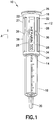
FIG. 1 is a perspective view of a syringe assembly including a flexible flange in accordance with an embodiment of the present invention; -
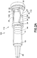
FIG. 2A is a perspective view of a syringe assembly in a pre-use position including a flexible flange according to an alternative design of the first embodiment of the invention; -
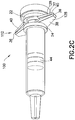
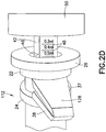
FIGS. 2B-2E are sequential perspective views of the flange formation and syringe actuation of a flexible flange arrangement according to the embodiment ofFIG. 2A , whereinFIG. 2B shows the flange fingers partially collapsed,FIG. 2C shows the flange fingers fully collapsed to form the flange,FIG. 2D shows the plunger in a withdrawn position, andFIG. 2E shows the syringe assembly after the plunger has been actuated; - For purposes of the description hereinafter, the terms "upper", "lower", "right", "left", "vertical", "horizontal", "top", "bottom", "lateral", "longitudinal", and derivatives thereof shall relate to the invention as it is oriented in the drawing figures. However, it is to be understood that the invention may assume various alternative variations, except where expressly specified to the contrary. It is also to be understood that the specific devices illustrated in the attached drawings, and described in the following specification, are simply exemplary embodiments of the invention. Hence, specific dimensions and other physical characteristics related to the embodiments disclosed herein are not to be considered as limiting.
- As shown in
FIG. 1 , a syringe assembly, generally denoted asreference numeral 10, includes aflexible flange 12 in accordance with an embodiment of the present invention. Thesyringe assembly 10 includes asyringe barrel 14 having aproximal end 16 anddistal end 18 and containing a fluid, such as a narcotic, diagnostic substance, or treatment substance, such as medication or a pain management substance therein. While described herein in terms of a filled or a pre-filled syringe, it is contemplated thatsyringe assembly 10 may be provided in a pre-filled state, or may be an empty syringe intended for filling immediately prior to use by the clinician. Thedistal end 18 includes an outlet opening 20, such as a luer tip or luer assembly for delivering the fluid stored within thesyringe barrel 14 therethrough. This outlet opening 20 can be configured for attachment to a needle assembly, an intravenous connection system, or any variety of delivery systems. - The
flexible flange 12 may include at least afirst member 22 and asecond member 24 disposed at least partially about thesyringe barrel 14. In one embodiment, thefirst member 22 and thesecond member 24 have a profile that at least partially corresponds to an exterior surface of thesyringe barrel 14 such that thefirst member 22 and thesecond member 24 may slide along the exterior surface of thesyringe barrel 14. In a further configuration, thefirst member 22 and thesecond member 24 are substantially circular and are adapted to surround the exterior surface of thesyringe barrel 14. In one embodiment, thefirst member 22 is configured for placement adjacent to theproximal end 16 of thesyringe barrel 14. Astop member 26 can be provided at theproximal end 16 of thesyringe barrel 14 to prevent theflange 12 from sliding off thebarrel 14 during use of thesyringe 10. Thesecond member 24 may be configured for placement about thesyringe barrel 14 at a predetermined distance away from thefirst member 22 along the length of thesyringe barrel 14. - At least one
flexible finger 28 extends between and connects the first andsecond members points FIG. 1 , a plurality offlexible fingers 28 can be provided between the first andsecond members syringe barrel 14. - At least one
bend point 36 is provided on the at least oneflexible finger 28. This at least onebend point 36 is located between said first and second connectingpoints points flexible fingers 28 may represent two or more separate pieces interconnected through a distinct hinge or other interconnecting member. For example,flexible fingers 28 may includefirst portion 37 andsecond portion 38 separated and interconnected with each other through a separate hinge element atbend point 36. In one particular embodiment, the separate discrete first andsecond finger portions bend point 36 representing a living hinge. The use of living hinges in the bend points 36 allows for theflexible fingers flange 40. Thus, thebend point 36 can separate the at least oneflexible finger first portion 37 and asecond portion 38. - Bend points 36 can be any type of hinge member, such as a living hinge, over the center hinge, or a region adapted to fold, compress, or stack upon itself. In a further embodiment, the bend points 36 may include a mechanism for controlled or automated advancement of the
flexible fingers 28 so as to cause first andsecond members flexible fingers 28 may include a mechanism intended to impart a bias therein, such thatflexible fingers 28 are biased into a hinged or folded state at bend points 36. In such an embodiment, a lock mechanism may be provided to maintainflexible fingers 28 in the first extended position, and upon release of the lock,flexible fingers 28 bend about bend points 36 toward and/or into the hinged or folded state. This may be accomplished by providing bend points 36 as an over the center type of hinge, wherein movement is initiated by the user by moving first andsecond members second member 24 proximally, which movement may store potential energy within one or more of the hinges at bend points 36. Once bend points 36 reach a predetermined bent position, the stored potential energy within bend points 36 releases, to automatically complete the bending at bend points 36, thereby movingflexible fingers 28 into the fully bent position for use. In one embodiment, automation of the hinge or hinges at bend points 36 may be accomplished through a hinged arm interconnection. - In a further embodiment, one or more extension spring members (not shown) may be provided interconnecting the first and
second members flexible fingers 28, for preloading thefinger flange 12 in a biased state toward the ready position withflexible fingers 28 bent in the final state for use. In such an embodiment, the mechanism is prevented from automatically or prematurely bending since the bias of the applied force is to collapse theflexible fingers 28 inwardly, but is prevented from doing so by the wall of thesyringe barrel 14. The user initiates the movement by moving first andsecond members second member 24 proximally, which buckles theflexible fingers 28 outward, and the spring member (not shown) can then complete the bending of theflexible fingers 28 so as to placeflexible flange 12 in the ready for use position. - As shown in
FIG. 2A , in an alternative embodiment, a pair offlexible fingers 128 may be positioned on opposing sides of thesyringe barrel 14 to form theflexible flange 112. - Reference is now made to
FIGS. 2A-2E which show the sequential operation of theflexible flange FIGS. 2A-2E show the functioning of the alternative design offlexible flange 112, however it is noted thatflexible flange 12, according to the design shown inFIG. 1 , would function in the same manner. -
FIG. 2A shows the syringe assembly with theflange 112 in the pre-use position. It is this position in which the syringe assembly has the smallest footprint and is packaged for controlled storage thereof. In this configuration, theflexible flange syringe barrel 14 in the initial position. A fluid is disposed within the interior of the syringe barrel, and theplunger 44, having aplunger rod 42 connected thereto, is also disposed within the interior of thesyringe barrel 14 in order to reduce the footprint of theoverall syringe assembly 10. As shown inFIG. 2B , upon the application of a force to theflexible fingers 128 in the direction of arrow B, thesecond member 24 slides along the periphery of thesyringe barrel 14 toward theproximal end 16 of thesyringe barrel 14 causing theflexible fingers 128 to bend aboutbend point 36 and extend in an outward, perpendicular direction with respect to thesyringe barrel 14. This force can be applied to either the secondcircular member 24 or a distal portion of theflexible fingers 128, as long as this force is applied between thebend point 36 and the secondcircular member 24 such as against thesecond portion 38 of theflexible finger 128. As shown inFIGS. 2B-2C , the application of a continued force in the direction of arrow B causes theflexible fingers 128 to collapse about thebend point 36 to bring thefirst portion 37 and thesecond portion 38 of theflexible fingers 128 into contact with one another to form aflange 40 at theproximal end 16 of thesyringe barrel 14. AlthoughFIGS. 1 and2A show a flexible flange which can create a pair offlanges 40 at opposed ends of thesyringe barrel 14, it is appreciated that a flexible finger arrangement can be provided so that only a single flange is created at one side of thesyringe barrel 14, resulting in a reduction of materials and production costs. - With reference to
FIG. 2D , upon creation of theflanges 40, the syringe is ready for use and theplunger rod 42 attached to plunger 44 (shown inFIGS. 2A-2C ) can be withdrawn from within the interior of thebarrel 14 by the application of force tothumb press 50. Alternatively, a spring-loaded push button (not shown) may be deployed to automatically advance theplunger rod 42 from within the interior of thesyringe barrel 14 in a proximal direction. According to one design, thisplunger 44 can include aretention notch 46 andindicia 48 such as for use with a metered plunger assembly.Stop 26 prevents theflange 112 from being pulled off thesyringe barrel 14 upon the application of the force thereto and during use of thesyringe 10. Upon deployment of thethumb press 50, theplunger 44 and associatedplunger rod 42 may be re-advanced into the interior of thesyringe barrel 14 to expel the fluid contents from therein. - In a further configuration, the
plunger 44 forms a liquid impermeable seal with a portion of the interior of thesyringe barrel 14 for maintaining the fluid contents in an uncontaminated state. It is appreciated that theflexible flange 12 of the invention can be used with any type ofsyringe assembly 10, particularly those which are placed in a controlled storage environment in which storage space is limited. These types of syringes include traditional pre-filled syringe assemblies, collapsed plunger rod designs, metered dose syringes, and the like. - It can be appreciated that the flexible flange of the invention locks in place during use and can then be unlocked or unassembled to its initial position where the flange extends substantially parallel with respect to the syringe body to allow for a reduced footprint in a sharps disposal container.
- While specific embodiments of the invention have been described in detail, it will be appreciated by those skilled in the art that various modifications and alternatives to those details could be developed in light of the overall teachings of the disclosure. Accordingly, the particular arrangements disclosed are meant to be illustrative only and not limiting as to the scope of invention which is to be given the full breadth of the claims appended and any and all equivalents thereof.
Claims (7)
- A syringe assembly (10) comprising:a syringe barrel (14) having a proximal end (16) and distal end (18), said distal end (18) including an outlet portion (20); anda flexible flange, the flexible flange comprising:at least a first and second circular member (22, 24), each of said circular members (22, 24) configured for placement about a syringe barrel (14), said first circular member (22) configured for placement adjacent to a proximal end (16) of the syringe barrel (14), said second circular member (24) configured for placement about the syringe barrel (14) a predetermined distance away from said first circular member (22) along the length of the syringe barrel (14);at least one flexible finger (28) extending between and connecting the first and second circular members (22, 24), at first and second connecting points (32, 34), the flexible finger (28) comprising a first portion (37) and a second portion (38) separated by at least one bend point (36) located between said first and second connecting points (32, 34),wherein the at least one flexible finger (28) is configured for collapsing upon the application of a proximal sliding force to at least one of said at least one flexible finger (28) and at least one of said circular members (22, 24) to form a flange (12) at the proximal end (16) of the syringe barrel (14),and the at least one bend point (36) allows said at least one flexible finger (28) to collapse upon the application of a sliding force,characterized in that,the bend point (36) is a hinge, andthe application of the proximal force causes the hinge (36) to bend such that the at least one flexible finger (28) collapses and the first and second portions (37, 38) of the at least one flexible finger (28) contact one another.
- The syringe assembly of claim 1, wherein said at least one flexible finger (28) comprises a pair of flexible fingers (28) positioned at opposite sides of the syringe barrel (14).
- The syringe assembly of claim 1, wherein said at least one flexible finger (28) comprises a plurality of flexible fingers (28) positioned around the syringe barrel (14).
- The syringe assembly (10) of claim 1, including a plunger rod (42) and plunger (44) positioned within said syringe barrel (14).
- The syringe assembly (10) of claim 4, wherein the plunger rod (42) includes indicia (48) thereon to allow for metered dosing.
- The syringe assembly (10) of claim 4, wherein the plunger rod (42) and plunger (44) are contained within the barrel (14) and the flexible flange (12) is in a collapsed position for packaging.
- The syringe assembly (10) of claim 1, wherein the hinge is a living hinge.
Priority Applications (1)
| Application Number | Priority Date | Filing Date | Title |
|---|---|---|---|
| EP19208317.8A EP3628350B1 (en) | 2009-08-21 | 2010-08-20 | Syringe assembly having a flexible or slidable flange |
Applications Claiming Priority (2)
| Application Number | Priority Date | Filing Date | Title |
|---|---|---|---|
| US23579209P | 2009-08-21 | 2009-08-21 | |
| PCT/US2010/046123 WO2011022621A1 (en) | 2009-08-21 | 2010-08-20 | Syringe assembly having a flexible or slidable flange |
Related Child Applications (1)
| Application Number | Title | Priority Date | Filing Date |
|---|---|---|---|
| EP19208317.8A Division EP3628350B1 (en) | 2009-08-21 | 2010-08-20 | Syringe assembly having a flexible or slidable flange |
Publications (2)
| Publication Number | Publication Date |
|---|---|
| EP2467181A1 EP2467181A1 (en) | 2012-06-27 |
| EP2467181B1 true EP2467181B1 (en) | 2019-11-20 |
Family
ID=43605915
Family Applications (2)
| Application Number | Title | Priority Date | Filing Date |
|---|---|---|---|
| EP19208317.8A Active EP3628350B1 (en) | 2009-08-21 | 2010-08-20 | Syringe assembly having a flexible or slidable flange |
| EP10747766.3A Active EP2467181B1 (en) | 2009-08-21 | 2010-08-20 | Syringe assembly having a flexible or slidable flange |
Family Applications Before (1)
| Application Number | Title | Priority Date | Filing Date |
|---|---|---|---|
| EP19208317.8A Active EP3628350B1 (en) | 2009-08-21 | 2010-08-20 | Syringe assembly having a flexible or slidable flange |
Country Status (6)
| Country | Link |
|---|---|
| US (3) | US20110046559A1 (en) |
| EP (2) | EP3628350B1 (en) |
| JP (2) | JP5665868B2 (en) |
| CN (1) | CN102573957B (en) |
| ES (1) | ES2931035T3 (en) |
| WO (1) | WO2011022621A1 (en) |
Families Citing this family (19)
| Publication number | Priority date | Publication date | Assignee | Title |
|---|---|---|---|---|
| MX366271B (en) | 2011-11-07 | 2019-07-04 | Safety Syringes Inc | Contact trigger release needle guard. |
| NL2011094C2 (en) * | 2013-07-04 | 2015-01-06 | Vlow Medical B V | Syringe with alternatively selectable graduations. |
| US9339606B2 (en) * | 2014-05-15 | 2016-05-17 | West Pharmaceutical Services, Inc. | Foldable finger flange for a syringe |
| GB201504319D0 (en) * | 2015-03-13 | 2015-04-29 | Owen Mumford Ltd | Syringe plunger and pressure indicator |
| US10213558B2 (en) * | 2016-03-28 | 2019-02-26 | Glenmark Pharmaceuticals S.A. | Drug delivery device |
| USD821572S1 (en) * | 2016-06-20 | 2018-06-26 | Medimmune, Llc | Drug delivery implement with translucent housing |
| USD822199S1 (en) * | 2016-06-22 | 2018-07-03 | Medimmune, Llc | Drug delivery implement |
| WO2018175792A1 (en) | 2017-03-22 | 2018-09-27 | Matthew Feinsod | Syringe |
| WO2018191101A1 (en) * | 2017-04-13 | 2018-10-18 | Becton, Dickinson And Company | Controlled delivery syringe device |
| JP7098171B2 (en) | 2017-06-16 | 2022-07-11 | クリーデンス メドシステムズ,インコーポレイテッド | Safety syringe system and method |
| US11090438B2 (en) | 2017-10-17 | 2021-08-17 | Bobby Nourani | Slanted syringe handle |
| CN109172952B (en) * | 2018-10-08 | 2023-09-26 | 东曜药业有限公司 | Syringe and auxiliary dosing device for a syringe |
| JP2022506951A (en) * | 2018-11-13 | 2022-01-17 | クリーデンス メドシステムズ,インコーポレイテッド | Systems and methods for injecting into multiple sites |
| USD987818S1 (en) | 2019-12-04 | 2023-05-30 | Bobby Nourani | Syringe adaptor |
| US11883635B2 (en) | 2020-06-17 | 2024-01-30 | Credence MedSystems | System and method for microdose injection |
| USD960359S1 (en) | 2020-06-19 | 2022-08-09 | Bobby Nourani | Syringe handle |
| USD967414S1 (en) | 2020-08-27 | 2022-10-18 | Laboratorios Farmaceuticos Rovi, S.A. | Syringe backstop |
| USD987819S1 (en) | 2021-02-18 | 2023-05-30 | Bobby Nourani | Syringe holder |
| US20230381427A1 (en) * | 2022-05-26 | 2023-11-30 | Bryna Hansen | Syringe seal |
Family Cites Families (77)
| Publication number | Priority date | Publication date | Assignee | Title |
|---|---|---|---|---|
| US772114A (en) * | 1903-11-20 | 1904-10-11 | Victor Pappenheim | Syringe. |
| US801912A (en) * | 1904-10-27 | 1905-10-17 | Gustave Rehmann | Syringe. |
| US1155012A (en) * | 1913-11-04 | 1915-09-28 | F S Banks & Company | Antitoxin-syringe. |
| US1142682A (en) * | 1914-10-27 | 1915-06-08 | Fairleigh S Dickinson | Syringe. |
| US1130493A (en) * | 1914-10-27 | 1915-03-02 | Fairleigh S Dickinson | Syringe. |
| US1331805A (en) * | 1917-07-09 | 1920-02-24 | White S Dental Mfg Co | Syringe |
| US1526056A (en) * | 1923-03-06 | 1925-02-10 | Eisele Logan | Finger rest and plunger control for all-glass hypodermic syringes |
| US1592335A (en) * | 1924-07-26 | 1926-07-13 | Brody William | Hypodermic syringe |
| US1649022A (en) * | 1925-01-28 | 1927-11-15 | Eisele Logan | Plunger control for hypodermic syringes |
| GB267323A (en) * | 1926-03-01 | 1927-03-17 | Konrad Stieglitz | Improvements in surgical syringes |
| US1798116A (en) * | 1928-02-09 | 1931-03-24 | Macgregor Instr Company | Syringe |
| US1834713A (en) * | 1929-04-23 | 1931-12-01 | Novocol Chemical Mfg Co Inc | Hypodermic syringe and the like |
| US1832533A (en) * | 1931-01-28 | 1931-11-17 | Leurner E Creasy | Syringe |
| US2047512A (en) * | 1934-02-12 | 1936-07-14 | Ralph A Kauffman | Hypodermic syringe |
| US2632445A (en) * | 1951-10-20 | 1953-03-24 | Sr John L Kas | Dosing hypodermic syringe |
| US2854975A (en) * | 1952-08-07 | 1958-10-07 | Miljam Instr Corp | Hypodermic syringe |
| US2829643A (en) * | 1952-10-27 | 1958-04-08 | Debaz Andre | Dismantlable injection syringe |
| US2911972A (en) * | 1954-09-14 | 1959-11-10 | Elinger Adolfo Scholcoff | Hypodermic syringe-ampulla |
| US2842128A (en) * | 1955-05-19 | 1958-07-08 | Becton Dickinson Co | Thumb ring for hypodermic syringe |
| US2823675A (en) * | 1957-11-04 | 1958-02-18 | Sciurba Joseph | Hypodermic syringe assembly |
| US3045673A (en) * | 1958-02-12 | 1962-07-24 | Becton Dickinson Co | Syringe assembly and attachment |
| US3076455A (en) * | 1958-12-19 | 1963-02-05 | Robert K Mcconnaughey | Holder for hypodermic syringe cartridges |
| US3039468A (en) * | 1959-01-07 | 1962-06-19 | Joseph L Price | Trocar and method of treating bloat |
| US3316909A (en) * | 1963-12-30 | 1967-05-02 | Pharmaseal Lab | Hypodermic syringe operable by one hand |
| GB1175184A (en) * | 1966-02-08 | 1969-12-23 | Arthur Bane | Improvements in Syringe Ampoules. |
| US3384082A (en) * | 1966-04-29 | 1968-05-21 | American Home Prod | Cartridge-syringe with movable finger grips |
| US3978858A (en) * | 1971-11-11 | 1976-09-07 | Mpl, Inc. | Glass tube and thermoplastic resin finger grip sleeve assembly |
| AT367301B (en) * | 1975-02-12 | 1982-06-25 | Buender Glas Gmbh | INJECTION SYRINGE |
| US4024865A (en) * | 1975-09-16 | 1977-05-24 | Hamilton Company | Syringe |
| US4212309A (en) * | 1978-09-28 | 1980-07-15 | Ballard Medical Products, Inc. | Blood gas sampler |
| US4314556A (en) * | 1980-04-21 | 1982-02-09 | Ma Austin C | Emergency syringe |
| US4364387A (en) * | 1980-12-18 | 1982-12-21 | Abbott Laboratories | Connecting device for medical liquid containers |
| US4540405A (en) * | 1983-07-12 | 1985-09-10 | Cilco, Inc. | Disposable syringe sleeve |
| US4664128A (en) * | 1983-12-16 | 1987-05-12 | Peter F. Lee, Inc | Single-hand controlled aspiration device |
| US4790828A (en) * | 1987-08-07 | 1988-12-13 | Dombrowski Mitchell P | Self-capping needle assembly |
| WO1989004681A1 (en) * | 1987-11-18 | 1989-06-01 | Catch 522 Pty. Limited | Single use syringe |
| US4927416A (en) * | 1987-12-02 | 1990-05-22 | National Medical Device Corporation | User-protective hypodermic syringe holder |
| US4904244A (en) * | 1988-02-22 | 1990-02-27 | Harsh Don J | Apparatus for safely removing needles from hypodermic syringes |
| US4950250A (en) * | 1988-02-23 | 1990-08-21 | Habley Medical Technology Corporation | Collapsible needle cover |
| US4909788A (en) * | 1988-12-14 | 1990-03-20 | Georges Egolf | Syringe with adjustable winged collar |
| US4932947A (en) * | 1989-02-17 | 1990-06-12 | Cardwell Dieter W | Syringe apparatus |
| US4990135A (en) * | 1989-08-29 | 1991-02-05 | Truesdale Jr R Grant | Inoculator and needle therefor |
| US5219338A (en) * | 1990-01-18 | 1993-06-15 | Haworth Warren D | Safety syringe with collapsible needle guard |
| US5115816A (en) * | 1991-01-24 | 1992-05-26 | Peter F. Lee, Inc. | Single-hand controlled fine needle aspiration device |
| IT221762Z2 (en) * | 1991-03-25 | 1994-10-20 | Salvatore Sapienza | MATT SYRINGE |
| US5338309A (en) | 1992-07-21 | 1994-08-16 | Becton, Dickinson And Company | Syringe having two component barrel |
| US5282792A (en) * | 1992-07-21 | 1994-02-01 | Becton, Dickinson And Company | Syringe having two component barrel |
| US5295972A (en) * | 1992-08-04 | 1994-03-22 | Metatech Corporation | Hypodermic syringe with protective cap |
| US5256132A (en) * | 1992-08-17 | 1993-10-26 | Snyders Robert V | Cardiac assist envelope for endoscopic application |
| US5509903A (en) * | 1992-11-19 | 1996-04-23 | Dennis T. Grendahl | Syringe having a flexible collar |
| US5250031A (en) * | 1992-12-14 | 1993-10-05 | The George Washington University | Locking needle cover |
| US5803918A (en) * | 1993-05-06 | 1998-09-08 | Becton Dickinson And Company | Syringe for medicinal purposes |
| US5348544A (en) * | 1993-11-24 | 1994-09-20 | Becton, Dickinson And Company | Single-handedly actuatable safety shield for needles |
| US5419775A (en) * | 1994-01-18 | 1995-05-30 | Allergan, Inc. | Syringe flange adapter and method |
| US5697918A (en) * | 1995-02-23 | 1997-12-16 | Ultradent Products, Inc. | Systems for storing and dispensing dental compositions |
| US5667495A (en) * | 1995-04-21 | 1997-09-16 | Becton Dickinson France S.A. | Backstop device for a syringe |
| US5607399A (en) * | 1995-09-22 | 1997-03-04 | Becton, Dickinson And Company | Backstop device for a flangeless syringe |
| US5582595A (en) * | 1995-09-28 | 1996-12-10 | Habley Medical Technology Corporation | Aspirating syringe having a plunger guide for a reciprocating plunger assembly |
| JP3743042B2 (en) * | 1995-12-27 | 2006-02-08 | 明治製菓株式会社 | Syringe aids |
| USD397790S (en) * | 1996-10-16 | 1998-09-01 | Seikagaku Kogyo Kabushiki Kaisha | Auxiliary finger flange for a syringe |
| US5833668A (en) * | 1996-11-21 | 1998-11-10 | Aguilar; David G. | Hypodermic syringe |
| DE19723851C1 (en) * | 1997-06-06 | 1998-10-08 | Schott Glas | Handle bar for prefilled disposable syringes |
| JP3283229B2 (en) * | 1998-02-16 | 2002-05-20 | 株式会社大協精工 | Syringe adapter system for chemical prefilled |
| US5997514A (en) * | 1999-01-15 | 1999-12-07 | Brocco Research, Usa | Finger grip collar for a syringe or cartridge barrel |
| USD434850S (en) * | 1999-01-15 | 2000-12-05 | Bracco Research,USA | Finger grip collar for a syringe or cartridge barrel |
| FR2830764B1 (en) * | 2001-10-15 | 2004-07-23 | Plastic Omnium Cie | SAFETY DEVICE FOR A SYRINGE |
| US6830564B2 (en) * | 2002-01-24 | 2004-12-14 | Robin Scott Gray | Syringe and method of using |
| GB0214452D0 (en) * | 2002-06-22 | 2002-07-31 | Liversidge Barry P | Medical needle assemblies |
| US20050159709A1 (en) * | 2004-01-20 | 2005-07-21 | Becton, Dickinson And Company | Safety shield system for a plastic syringe |
| FR2866573B1 (en) * | 2004-02-24 | 2006-06-23 | Pascal Claude Henri Magnan | INVIOLABILITY DEVICE FOR SYRINGE AND SYRINGE EQUIPPED WITH SUCH A DEVICE |
| GB0414054D0 (en) * | 2004-06-23 | 2004-07-28 | Owen Mumford Ltd | Improvements relating to automatic injection devices |
| JP4365750B2 (en) * | 2004-08-20 | 2009-11-18 | ローム株式会社 | Semiconductor chip manufacturing method and semiconductor device manufacturing method |
| US20070191780A1 (en) * | 2006-02-16 | 2007-08-16 | Pankaj Modi | Drug delivery device |
| EP2896421A1 (en) * | 2007-04-20 | 2015-07-22 | Jennifer Barbour | Ergonomic syringe |
| US20090036839A1 (en) * | 2007-07-25 | 2009-02-05 | Tom Phalen | Ergonomic adaptor for repeated injections |
| USD581527S1 (en) * | 2007-08-28 | 2008-11-25 | West Pharmaceutical Services, Inc. | Syringe backstop |
| US9339606B2 (en) * | 2014-05-15 | 2016-05-17 | West Pharmaceutical Services, Inc. | Foldable finger flange for a syringe |
-
2010
- 2010-08-19 US US12/859,521 patent/US20110046559A1/en not_active Abandoned
- 2010-08-20 WO PCT/US2010/046123 patent/WO2011022621A1/en active Application Filing
- 2010-08-20 EP EP19208317.8A patent/EP3628350B1/en active Active
- 2010-08-20 CN CN201080043715.5A patent/CN102573957B/en active Active
- 2010-08-20 EP EP10747766.3A patent/EP2467181B1/en active Active
- 2010-08-20 ES ES19208317T patent/ES2931035T3/en active Active
- 2010-08-20 JP JP2012525719A patent/JP5665868B2/en active Active
-
2014
- 2014-01-24 US US14/163,381 patent/US10112014B2/en active Active
- 2014-07-01 JP JP2014135863A patent/JP5819487B2/en active Active
-
2018
- 2018-09-28 US US16/145,274 patent/US10576209B2/en active Active
Non-Patent Citations (1)
| Title |
|---|
| None * |
Also Published As
| Publication number | Publication date |
|---|---|
| WO2011022621A1 (en) | 2011-02-24 |
| US20110046559A1 (en) | 2011-02-24 |
| US10112014B2 (en) | 2018-10-30 |
| JP2014208276A (en) | 2014-11-06 |
| US20140142517A1 (en) | 2014-05-22 |
| ES2931035T3 (en) | 2022-12-23 |
| EP3628350B1 (en) | 2022-09-28 |
| US20190030252A1 (en) | 2019-01-31 |
| EP2467181A1 (en) | 2012-06-27 |
| US10576209B2 (en) | 2020-03-03 |
| CN102573957B (en) | 2014-12-10 |
| JP2013502289A (en) | 2013-01-24 |
| EP3628350A1 (en) | 2020-04-01 |
| JP5665868B2 (en) | 2015-02-04 |
| JP5819487B2 (en) | 2015-11-24 |
| CN102573957A (en) | 2012-07-11 |
Similar Documents
| Publication | Publication Date | Title |
|---|---|---|
| US10576209B2 (en) | Syringe assembly having a flexible or slidable flange | |
| US11724038B2 (en) | Syringe assembly with inverse delivery | |
| US10894128B2 (en) | Drive control mechanisms and automatic injectors for injectable cartridges | |
| US8657793B2 (en) | Space saving plunger cap and rod assembly | |
| US9295783B2 (en) | Syringe having a collapsible plunger rod | |
| EP2760511B1 (en) | Syringe having pivoting arm plunger rod | |
| US8636702B2 (en) | Magnifying collapsed plunger rod | |
| EP2968063B1 (en) | Medicament container carrier and adapter | |
| US9119919B2 (en) | Syringe having a squeeze-fit plunger rod | |
| JP2020503137A (en) | Injector and method of operating the injector | |
| CN104582767A (en) | Retractable needle safety syringes | |
| WO2009024806A1 (en) | Single-use syringe allowing aspiration |
Legal Events
| Date | Code | Title | Description |
|---|---|---|---|
| PUAI | Public reference made under article 153(3) epc to a published international application that has entered the european phase |
Free format text: ORIGINAL CODE: 0009012 |
|
| 17P | Request for examination filed |
Effective date: 20120228 |
|
| AK | Designated contracting states |
Kind code of ref document: A1 Designated state(s): AL AT BE BG CH CY CZ DE DK EE ES FI FR GB GR HR HU IE IS IT LI LT LU LV MC MK MT NL NO PL PT RO SE SI SK SM TR |
|
| DAX | Request for extension of the european patent (deleted) | ||
| 17Q | First examination report despatched |
Effective date: 20160413 |
|
| STAA | Information on the status of an ep patent application or granted ep patent |
Free format text: STATUS: EXAMINATION IS IN PROGRESS |
|
| REG | Reference to a national code |
Ref country code: DE Ref legal event code: R079 Ref document number: 602010062034 Country of ref document: DE Free format text: PREVIOUS MAIN CLASS: A61M0005310000 Ipc: A61M0005315000 |
|
| GRAP | Despatch of communication of intention to grant a patent |
Free format text: ORIGINAL CODE: EPIDOSNIGR1 |
|
| STAA | Information on the status of an ep patent application or granted ep patent |
Free format text: STATUS: GRANT OF PATENT IS INTENDED |
|
| RIC1 | Information provided on ipc code assigned before grant |
Ipc: A61M 5/31 20060101ALI20190522BHEP Ipc: A61M 5/315 20060101AFI20190522BHEP |
|
| INTG | Intention to grant announced |
Effective date: 20190607 |
|
| GRAS | Grant fee paid |
Free format text: ORIGINAL CODE: EPIDOSNIGR3 |
|
| GRAA | (expected) grant |
Free format text: ORIGINAL CODE: 0009210 |
|
| STAA | Information on the status of an ep patent application or granted ep patent |
Free format text: STATUS: THE PATENT HAS BEEN GRANTED |
|
| AK | Designated contracting states |
Kind code of ref document: B1 Designated state(s): AL AT BE BG CH CY CZ DE DK EE ES FI FR GB GR HR HU IE IS IT LI LT LU LV MC MK MT NL NO PL PT RO SE SI SK SM TR |
|
| REG | Reference to a national code |
Ref country code: GB Ref legal event code: FG4D |
|
| REG | Reference to a national code |
Ref country code: CH Ref legal event code: EP |
|
| REG | Reference to a national code |
Ref country code: DE Ref legal event code: R096 Ref document number: 602010062034 Country of ref document: DE |
|
| REG | Reference to a national code |
Ref country code: IE Ref legal event code: FG4D |
|
| REG | Reference to a national code |
Ref country code: AT Ref legal event code: REF Ref document number: 1203472 Country of ref document: AT Kind code of ref document: T Effective date: 20191215 |
|
| REG | Reference to a national code |
Ref country code: NL Ref legal event code: MP Effective date: 20191120 |
|
| REG | Reference to a national code |
Ref country code: LT Ref legal event code: MG4D |
|
| PG25 | Lapsed in a contracting state [announced via postgrant information from national office to epo] |
Ref country code: FI Free format text: LAPSE BECAUSE OF FAILURE TO SUBMIT A TRANSLATION OF THE DESCRIPTION OR TO PAY THE FEE WITHIN THE PRESCRIBED TIME-LIMIT Effective date: 20191120 Ref country code: BG Free format text: LAPSE BECAUSE OF FAILURE TO SUBMIT A TRANSLATION OF THE DESCRIPTION OR TO PAY THE FEE WITHIN THE PRESCRIBED TIME-LIMIT Effective date: 20200220 Ref country code: NO Free format text: LAPSE BECAUSE OF FAILURE TO SUBMIT A TRANSLATION OF THE DESCRIPTION OR TO PAY THE FEE WITHIN THE PRESCRIBED TIME-LIMIT Effective date: 20200220 Ref country code: GR Free format text: LAPSE BECAUSE OF FAILURE TO SUBMIT A TRANSLATION OF THE DESCRIPTION OR TO PAY THE FEE WITHIN THE PRESCRIBED TIME-LIMIT Effective date: 20200221 Ref country code: SE Free format text: LAPSE BECAUSE OF FAILURE TO SUBMIT A TRANSLATION OF THE DESCRIPTION OR TO PAY THE FEE WITHIN THE PRESCRIBED TIME-LIMIT Effective date: 20191120 Ref country code: LV Free format text: LAPSE BECAUSE OF FAILURE TO SUBMIT A TRANSLATION OF THE DESCRIPTION OR TO PAY THE FEE WITHIN THE PRESCRIBED TIME-LIMIT Effective date: 20191120 Ref country code: NL Free format text: LAPSE BECAUSE OF FAILURE TO SUBMIT A TRANSLATION OF THE DESCRIPTION OR TO PAY THE FEE WITHIN THE PRESCRIBED TIME-LIMIT Effective date: 20191120 Ref country code: ES Free format text: LAPSE BECAUSE OF FAILURE TO SUBMIT A TRANSLATION OF THE DESCRIPTION OR TO PAY THE FEE WITHIN THE PRESCRIBED TIME-LIMIT Effective date: 20191120 Ref country code: LT Free format text: LAPSE BECAUSE OF FAILURE TO SUBMIT A TRANSLATION OF THE DESCRIPTION OR TO PAY THE FEE WITHIN THE PRESCRIBED TIME-LIMIT Effective date: 20191120 |
|
| PG25 | Lapsed in a contracting state [announced via postgrant information from national office to epo] |
Ref country code: IS Free format text: LAPSE BECAUSE OF FAILURE TO SUBMIT A TRANSLATION OF THE DESCRIPTION OR TO PAY THE FEE WITHIN THE PRESCRIBED TIME-LIMIT Effective date: 20200320 Ref country code: HR Free format text: LAPSE BECAUSE OF FAILURE TO SUBMIT A TRANSLATION OF THE DESCRIPTION OR TO PAY THE FEE WITHIN THE PRESCRIBED TIME-LIMIT Effective date: 20191120 |
|
| PG25 | Lapsed in a contracting state [announced via postgrant information from national office to epo] |
Ref country code: AL Free format text: LAPSE BECAUSE OF FAILURE TO SUBMIT A TRANSLATION OF THE DESCRIPTION OR TO PAY THE FEE WITHIN THE PRESCRIBED TIME-LIMIT Effective date: 20191120 |
|
| PG25 | Lapsed in a contracting state [announced via postgrant information from national office to epo] |
Ref country code: PT Free format text: LAPSE BECAUSE OF FAILURE TO SUBMIT A TRANSLATION OF THE DESCRIPTION OR TO PAY THE FEE WITHIN THE PRESCRIBED TIME-LIMIT Effective date: 20200412 Ref country code: EE Free format text: LAPSE BECAUSE OF FAILURE TO SUBMIT A TRANSLATION OF THE DESCRIPTION OR TO PAY THE FEE WITHIN THE PRESCRIBED TIME-LIMIT Effective date: 20191120 Ref country code: DK Free format text: LAPSE BECAUSE OF FAILURE TO SUBMIT A TRANSLATION OF THE DESCRIPTION OR TO PAY THE FEE WITHIN THE PRESCRIBED TIME-LIMIT Effective date: 20191120 Ref country code: CZ Free format text: LAPSE BECAUSE OF FAILURE TO SUBMIT A TRANSLATION OF THE DESCRIPTION OR TO PAY THE FEE WITHIN THE PRESCRIBED TIME-LIMIT Effective date: 20191120 Ref country code: RO Free format text: LAPSE BECAUSE OF FAILURE TO SUBMIT A TRANSLATION OF THE DESCRIPTION OR TO PAY THE FEE WITHIN THE PRESCRIBED TIME-LIMIT Effective date: 20191120 |
|
| REG | Reference to a national code |
Ref country code: AT Ref legal event code: MK05 Ref document number: 1203472 Country of ref document: AT Kind code of ref document: T Effective date: 20191120 |
|
| REG | Reference to a national code |
Ref country code: DE Ref legal event code: R097 Ref document number: 602010062034 Country of ref document: DE |
|
| PG25 | Lapsed in a contracting state [announced via postgrant information from national office to epo] |
Ref country code: SM Free format text: LAPSE BECAUSE OF FAILURE TO SUBMIT A TRANSLATION OF THE DESCRIPTION OR TO PAY THE FEE WITHIN THE PRESCRIBED TIME-LIMIT Effective date: 20191120 Ref country code: SK Free format text: LAPSE BECAUSE OF FAILURE TO SUBMIT A TRANSLATION OF THE DESCRIPTION OR TO PAY THE FEE WITHIN THE PRESCRIBED TIME-LIMIT Effective date: 20191120 |
|
| PLBE | No opposition filed within time limit |
Free format text: ORIGINAL CODE: 0009261 |
|
| STAA | Information on the status of an ep patent application or granted ep patent |
Free format text: STATUS: NO OPPOSITION FILED WITHIN TIME LIMIT |
|
| 26N | No opposition filed |
Effective date: 20200821 |
|
| PG25 | Lapsed in a contracting state [announced via postgrant information from national office to epo] |
Ref country code: SI Free format text: LAPSE BECAUSE OF FAILURE TO SUBMIT A TRANSLATION OF THE DESCRIPTION OR TO PAY THE FEE WITHIN THE PRESCRIBED TIME-LIMIT Effective date: 20191120 Ref country code: AT Free format text: LAPSE BECAUSE OF FAILURE TO SUBMIT A TRANSLATION OF THE DESCRIPTION OR TO PAY THE FEE WITHIN THE PRESCRIBED TIME-LIMIT Effective date: 20191120 Ref country code: PL Free format text: LAPSE BECAUSE OF FAILURE TO SUBMIT A TRANSLATION OF THE DESCRIPTION OR TO PAY THE FEE WITHIN THE PRESCRIBED TIME-LIMIT Effective date: 20191120 |
|
| PG25 | Lapsed in a contracting state [announced via postgrant information from national office to epo] |
Ref country code: MC Free format text: LAPSE BECAUSE OF FAILURE TO SUBMIT A TRANSLATION OF THE DESCRIPTION OR TO PAY THE FEE WITHIN THE PRESCRIBED TIME-LIMIT Effective date: 20191120 |
|
| PG25 | Lapsed in a contracting state [announced via postgrant information from national office to epo] |
Ref country code: LU Free format text: LAPSE BECAUSE OF NON-PAYMENT OF DUE FEES Effective date: 20200820 |
|
| REG | Reference to a national code |
Ref country code: BE Ref legal event code: MM Effective date: 20200831 |
|
| PG25 | Lapsed in a contracting state [announced via postgrant information from national office to epo] |
Ref country code: BE Free format text: LAPSE BECAUSE OF NON-PAYMENT OF DUE FEES Effective date: 20200831 Ref country code: IE Free format text: LAPSE BECAUSE OF NON-PAYMENT OF DUE FEES Effective date: 20200820 |
|
| PG25 | Lapsed in a contracting state [announced via postgrant information from national office to epo] |
Ref country code: TR Free format text: LAPSE BECAUSE OF FAILURE TO SUBMIT A TRANSLATION OF THE DESCRIPTION OR TO PAY THE FEE WITHIN THE PRESCRIBED TIME-LIMIT Effective date: 20191120 Ref country code: MT Free format text: LAPSE BECAUSE OF FAILURE TO SUBMIT A TRANSLATION OF THE DESCRIPTION OR TO PAY THE FEE WITHIN THE PRESCRIBED TIME-LIMIT Effective date: 20191120 Ref country code: CY Free format text: LAPSE BECAUSE OF FAILURE TO SUBMIT A TRANSLATION OF THE DESCRIPTION OR TO PAY THE FEE WITHIN THE PRESCRIBED TIME-LIMIT Effective date: 20191120 |
|
| PG25 | Lapsed in a contracting state [announced via postgrant information from national office to epo] |
Ref country code: MK Free format text: LAPSE BECAUSE OF FAILURE TO SUBMIT A TRANSLATION OF THE DESCRIPTION OR TO PAY THE FEE WITHIN THE PRESCRIBED TIME-LIMIT Effective date: 20191120 |
|
| PGFP | Annual fee paid to national office [announced via postgrant information from national office to epo] |
Ref country code: IT Payment date: 20230720 Year of fee payment: 14 Ref country code: GB Payment date: 20230720 Year of fee payment: 14 Ref country code: CH Payment date: 20230902 Year of fee payment: 14 |
|
| PGFP | Annual fee paid to national office [announced via postgrant information from national office to epo] |
Ref country code: FR Payment date: 20230720 Year of fee payment: 14 |
|
| PGFP | Annual fee paid to national office [announced via postgrant information from national office to epo] |
Ref country code: DE Payment date: 20240723 Year of fee payment: 15 |