EP2467006B1 - Remote radio unit - Google Patents
Remote radio unit Download PDFInfo
- Publication number
- EP2467006B1 EP2467006B1 EP10813358.8A EP10813358A EP2467006B1 EP 2467006 B1 EP2467006 B1 EP 2467006B1 EP 10813358 A EP10813358 A EP 10813358A EP 2467006 B1 EP2467006 B1 EP 2467006B1
- Authority
- EP
- European Patent Office
- Prior art keywords
- radiating pipes
- rru
- evaporator
- shell body
- radiating
- Prior art date
- Legal status (The legal status is an assumption and is not a legal conclusion. Google has not performed a legal analysis and makes no representation as to the accuracy of the status listed.)
- Not-in-force
Links
Images
Classifications
-
- H—ELECTRICITY
- H05—ELECTRIC TECHNIQUES NOT OTHERWISE PROVIDED FOR
- H05K—PRINTED CIRCUITS; CASINGS OR CONSTRUCTIONAL DETAILS OF ELECTRIC APPARATUS; MANUFACTURE OF ASSEMBLAGES OF ELECTRICAL COMPONENTS
- H05K7/00—Constructional details common to different types of electric apparatus
- H05K7/20—Modifications to facilitate cooling, ventilating, or heating
- H05K7/2029—Modifications to facilitate cooling, ventilating, or heating using a liquid coolant with phase change in electronic enclosures
- H05K7/20336—Heat pipes, e.g. wicks or capillary pumps
-
- F—MECHANICAL ENGINEERING; LIGHTING; HEATING; WEAPONS; BLASTING
- F28—HEAT EXCHANGE IN GENERAL
- F28D—HEAT-EXCHANGE APPARATUS, NOT PROVIDED FOR IN ANOTHER SUBCLASS, IN WHICH THE HEAT-EXCHANGE MEDIA DO NOT COME INTO DIRECT CONTACT
- F28D15/00—Heat-exchange apparatus with the intermediate heat-transfer medium in closed tubes passing into or through the conduit walls ; Heat-exchange apparatus employing intermediate heat-transfer medium or bodies
- F28D15/02—Heat-exchange apparatus with the intermediate heat-transfer medium in closed tubes passing into or through the conduit walls ; Heat-exchange apparatus employing intermediate heat-transfer medium or bodies in which the medium condenses and evaporates, e.g. heat pipes
- F28D15/0233—Heat-exchange apparatus with the intermediate heat-transfer medium in closed tubes passing into or through the conduit walls ; Heat-exchange apparatus employing intermediate heat-transfer medium or bodies in which the medium condenses and evaporates, e.g. heat pipes the conduits having a particular shape, e.g. non-circular cross-section, annular
-
- F—MECHANICAL ENGINEERING; LIGHTING; HEATING; WEAPONS; BLASTING
- F28—HEAT EXCHANGE IN GENERAL
- F28D—HEAT-EXCHANGE APPARATUS, NOT PROVIDED FOR IN ANOTHER SUBCLASS, IN WHICH THE HEAT-EXCHANGE MEDIA DO NOT COME INTO DIRECT CONTACT
- F28D15/00—Heat-exchange apparatus with the intermediate heat-transfer medium in closed tubes passing into or through the conduit walls ; Heat-exchange apparatus employing intermediate heat-transfer medium or bodies
- F28D15/02—Heat-exchange apparatus with the intermediate heat-transfer medium in closed tubes passing into or through the conduit walls ; Heat-exchange apparatus employing intermediate heat-transfer medium or bodies in which the medium condenses and evaporates, e.g. heat pipes
- F28D15/0266—Heat-exchange apparatus with the intermediate heat-transfer medium in closed tubes passing into or through the conduit walls ; Heat-exchange apparatus employing intermediate heat-transfer medium or bodies in which the medium condenses and evaporates, e.g. heat pipes with separate evaporating and condensing chambers connected by at least one conduit; Loop-type heat pipes; with multiple or common evaporating or condensing chambers
-
- G—PHYSICS
- G06—COMPUTING OR CALCULATING; COUNTING
- G06F—ELECTRIC DIGITAL DATA PROCESSING
- G06F1/00—Details not covered by groups G06F3/00 - G06F13/00 and G06F21/00
- G06F1/16—Constructional details or arrangements
- G06F1/20—Cooling means
-
- H—ELECTRICITY
- H10—SEMICONDUCTOR DEVICES; ELECTRIC SOLID-STATE DEVICES NOT OTHERWISE PROVIDED FOR
- H10W—GENERIC PACKAGES, INTERCONNECTIONS, CONNECTORS OR OTHER CONSTRUCTIONAL DETAILS OF DEVICES COVERED BY CLASS H10
- H10W40/00—Arrangements for thermal protection or thermal control
- H10W40/40—Arrangements for thermal protection or thermal control involving heat exchange by flowing fluids
- H10W40/43—Arrangements for thermal protection or thermal control involving heat exchange by flowing fluids by flowing gases, e.g. forced air cooling
-
- H—ELECTRICITY
- H10—SEMICONDUCTOR DEVICES; ELECTRIC SOLID-STATE DEVICES NOT OTHERWISE PROVIDED FOR
- H10W—GENERIC PACKAGES, INTERCONNECTIONS, CONNECTORS OR OTHER CONSTRUCTIONAL DETAILS OF DEVICES COVERED BY CLASS H10
- H10W40/00—Arrangements for thermal protection or thermal control
- H10W40/40—Arrangements for thermal protection or thermal control involving heat exchange by flowing fluids
- H10W40/47—Arrangements for thermal protection or thermal control involving heat exchange by flowing fluids by flowing liquids, e.g. forced water cooling
-
- H—ELECTRICITY
- H10—SEMICONDUCTOR DEVICES; ELECTRIC SOLID-STATE DEVICES NOT OTHERWISE PROVIDED FOR
- H10W—GENERIC PACKAGES, INTERCONNECTIONS, CONNECTORS OR OTHER CONSTRUCTIONAL DETAILS OF DEVICES COVERED BY CLASS H10
- H10W40/00—Arrangements for thermal protection or thermal control
- H10W40/70—Fillings or auxiliary members in containers or in encapsulations for thermal protection or control
- H10W40/73—Fillings or auxiliary members in containers or in encapsulations for thermal protection or control for cooling by change of state
Definitions
- the present invention relates to a communication device, and in particular, to a Remote Radio Unit (RRU)
- RRU Remote Radio Unit
- An RRU is a novel disposed network coverage mode, in the mode, high-capacity macro cell base stations are centrally placed in an accessible central equipment room, baseband parts are processed centrally, and radio frequency modules in a base station is pulled to the RRU by adopting optical fibers, and are separately placed on stations determined by the network planning, thereby saving a large quantity of equipment rooms required by the regular solution; and meanwhile, by adopting a high-capacity macro base station to support pulling a large quantity of optical fibers far away, the conversion between the capacity and the coverage may be achieved. Because of the foregoing advantages of the RRU, the RRU is widely applied.
- An existing RRU having a shell includes an RRU radiator structural member and a shell; the RRU radiator structural member includes an RRU and a radiator, a radiating portion of the RRU is connected to the radiator, the radiating portion of the RRU specifically may be a power amplifier module, a duplexer module, or a transceiver module of the RRU, and the radiator includes radiating fins configured to exchange heat with the air so as to achieve radiating.
- the shell surrounds the RRU and the radiator, and the shell is made of a plastic material, and is connected to the RRU radiator structural member through screws, which functions to be aesthetic and prevent solar radiation.
- the inventors find that: the existing RRU only uses the radiating fins of the radiator to perform heat exchange with the air to achieve radiating, and therefore, overall system radiating efficiency is not high.
- CN 201 197 257 Y shows a heat dissipating device that comprises a radiator, a fan, and a cover with a solar battery, in which the radiating ability is implemented by arranging the fan opposite to the radiator and providing the fan with power supply through the solar battery.
- US 6,388,882 B1 shows a thermal energy management architecture that comprises several levels of heat transfer devices, in which the fourth level of heat transfer devices comprise means for busing thermal energy that are thermally driven and operatively engaged with at least one of first to four levels of heat transfer devices.
- An embodiment of the present invention provides an RRU, which is capable of improving radiating efficiency.
- An RRU includes an RRU radiator structural member and a shell, the shell includes an evaporator, radiating pipes and a shell body, the inside of the evaporator is in communication with the radiating pipes to form a loop for holding a phase change medium, and the radiating pipes are disposed on the shell body for transferring heat to the shell; and the evaporator is connected to a radiator of the RRU radiator structural member.
- the evaporator included by the shell in the RRU is connected to the radiator of the RRU radiator structural member, so the heat of the radiator can be transferred to the evaporator, and the heat may be further transferred to the shell through the radiating pipes since the evaporator is connected to the radiating pipes, so that the shell participates in the radiating, thereby improving the radiating efficiency and improving the work stability of the RRU.
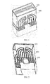
- FIG 1 describes an RRU according to an embodiment of the present invention, which includes an RRU radiator structural member 101 and a shell 102.
- the structure of the shell 102 is shown in FIG 2 , and the shell 102 includes an evaporator 1021, radiating pipes 1022 and a shell body 1023.
- the inside of the evaporator 1021 is in communication with the radiating pipes 1022, and the radiating pipes 1022 are disposed on a surface of the shell body 1023.
- the radiating pipes 1022 may be made of a metal material, for example, metal with good heat conducting performance such as copper and aluminum; and may also be made of a plastic material, such as heat conducting plastic.
- the material of the shell body 1023 may be the same as the material of the radiating pipes 1022, and may also be different from the material of the radiating pipes 1022.
- the length and the shape of the radiating pipes 1022 may be designed or assembled as required.
- the evaporator 1021 may be fixed on the shell body 1023; for example, the evaporator 1021 may be fixed on the shell body 1023 by adopting screws or buckles, thereby ensuring that the evaporator 1021 is tightly connected to the shell body 1023.
- the evaporator 1021 is connected to a radiator of the RRU radiator structural member 101.
- the evaporator included by the shell in the RRU according to the embodiment of the present invention is connected to the radiator of the RRU radiator structural member, so that the heat of the radiator can be transferred to the evaporator, and the heat may be further transferred through the radiating pipes since the evaporator is connected to the radiating pipes, thereby improving the radiating efficiency and improving the work stability of the RRU.
- the evaporator in order to enable the evaporator to maintain the position fixed after the evaporator is connected to the radiator, the evaporator may be locked through screws, thereby ensuring that the heat of the radiator can be transferred to the evaporator.
- a groove is disposed in the evaporator 1021, so that the groove may be in communication with the radiating pipes 1022 to form a loop, thereby further improving the heat conduction efficiency.
- a phase changeable medium may be filled in the radiating pipes 1022, and the medium may be a medium having an efficient phase change heat exchange capability such as water, ammonia, or Freon ® .
- the heat may be transferred in the radiating pipes through the phase changeable medium, and then the radiating is performed through the radiating pipes; further, when the radiating pipes are in communication with the groove of the evaporator to form the loop, the heat may be transferred more quickly between the evaporator and the radiating pipes through the phase changeable medium, thereby improving the radiating efficiency.
- the radiating pipes 1022 may be embedded in the shell body 1023, so the radiating pipes 1022 and the shell body 1023 may be manufactured through integral molding; for example, when the shell body 1023 is made of the plastic material, the blow-up process may be performed on the shell body 1023 to form the radiating pipes 1022, and in this case, the radiating pipes 1022 is also made of the plastic material; or when the shell body 1023 is made of the plastic material, and the radiating pipes 1022 is made of the metal material, the injection molding may be performed on the radiating pipes 1022.
- the radiating pipes 1022 may not be embedded in the shell body 1023, and in this case, the radiating pipes 1022 and the evaporator 1021 may be located at two sides of a surface of the shell body 1023 respectively.
- the radiating pipes 1022 and the shell body 1023 may be respectively machined, and then are assembled with the evaporator 1021 to form the shell 102; compared with the practice that the radiating pipes 1022 and the shell body 1023 are manufactured through the integral molding, the foregoing practice may reduce the machining difficulty and the manufacturing cost, and meanwhile the design flexibility may also be improved.
- a ventilation hole may be opened on the shell body 1023, thereby satisfying requirements of the RRU for the ventilation quantity under different environments.
- the horizontal position of the radiator is not higher than that of the radiating pipes, that is to say, the horizontal position of the radiator is lower than or horizontal to that of the radiating pipes.
- the gasified medium generated by the evaporator can provide a sufficient acting force to enable the phase change medium to flow in the loop formed by the evaporator and the radiating pipes, or additional power elements are mounted in the radiating pipes, the evaporator may also be higher than the radiating pipes.
Landscapes
- Engineering & Computer Science (AREA)
- Physics & Mathematics (AREA)
- Thermal Sciences (AREA)
- Microelectronics & Electronic Packaging (AREA)
- General Engineering & Computer Science (AREA)
- Life Sciences & Earth Sciences (AREA)
- Sustainable Development (AREA)
- Mechanical Engineering (AREA)
- Theoretical Computer Science (AREA)
- Human Computer Interaction (AREA)
- General Physics & Mathematics (AREA)
- Cooling Or The Like Of Electrical Apparatus (AREA)
Description
- The present invention relates to a communication device, and in particular, to a Remote Radio Unit (RRU)
- An RRU is a novel disposed network coverage mode, in the mode, high-capacity macro cell base stations are centrally placed in an accessible central equipment room, baseband parts are processed centrally, and radio frequency modules in a base station is pulled to the RRU by adopting optical fibers, and are separately placed on stations determined by the network planning, thereby saving a large quantity of equipment rooms required by the regular solution; and meanwhile, by adopting a high-capacity macro base station to support pulling a large quantity of optical fibers far away, the conversion between the capacity and the coverage may be achieved. Because of the foregoing advantages of the RRU, the RRU is widely applied.
- An existing RRU having a shell includes an RRU radiator structural member and a shell; the RRU radiator structural member includes an RRU and a radiator, a radiating portion of the RRU is connected to the radiator, the radiating portion of the RRU specifically may be a power amplifier module, a duplexer module, or a transceiver module of the RRU, and the radiator includes radiating fins configured to exchange heat with the air so as to achieve radiating. The shell surrounds the RRU and the radiator, and the shell is made of a plastic material, and is connected to the RRU radiator structural member through screws, which functions to be aesthetic and prevent solar radiation.
- In the research for the prior art, the inventors find that: the existing RRU only uses the radiating fins of the radiator to perform heat exchange with the air to achieve radiating, and therefore, overall system radiating efficiency is not high.
-
CN 201 197 257 Y shows a heat dissipating device that comprises a radiator, a fan, and a cover with a solar battery, in which the radiating ability is implemented by arranging the fan opposite to the radiator and providing the fan with power supply through the solar battery. -
US 6,388,882 B1 shows a thermal energy management architecture that comprises several levels of heat transfer devices, in which the fourth level of heat transfer devices comprise means for busing thermal energy that are thermally driven and operatively engaged with at least one of first to four levels of heat transfer devices. - An embodiment of the present invention provides an RRU, which is capable of improving radiating efficiency.
- An RRU includes an RRU radiator structural member and a shell, the shell includes an evaporator, radiating pipes and a shell body, the inside of the evaporator is in communication with the radiating pipes to form a loop for holding a phase change medium, and the radiating pipes are disposed on the shell body for transferring heat to the shell; and
the evaporator is connected to a radiator of the RRU radiator structural member. - It may be seen from the foregoing technical solutions according to the embodiments of the present invention that, in the embodiments of the present invention, the evaporator included by the shell in the RRU is connected to the radiator of the RRU radiator structural member, so the heat of the radiator can be transferred to the evaporator, and the heat may be further transferred to the shell through the radiating pipes since the evaporator is connected to the radiating pipes, so that the shell participates in the radiating, thereby improving the radiating efficiency and improving the work stability of the RRU.
- To illustrate the technical solutions according to the embodiments of the present invention or in the prior art more clearly, the accompanying drawings for describing the present invention or the prior art are introduced briefly in the following. Apparently, the accompanying drawings in the following description are only about some embodiments of the present invention, and person of ordinary skill in the art can derive other drawings from the accompanying drawings without creative efforts.
-
FIG 1 is a structural diagram of an RRU according to an embodiment of the present invention; and -
FIG. 2 is a structural diagram of a shell in the RRU according to the embodiment of the present invention. - The technical solutions according to the embodiments of the present invention will be clearly described in the following with reference to the accompanying drawings. It is obvious that the embodiments to be described are only a part rather than all of the embodiments of the present invention. All other embodiments obtained by persons skilled in the art based on the embodiments of the present invention without creative effects shall fall within the protection scope of the present invention.
-
FIG 1 describes an RRU according to an embodiment of the present invention, which includes an RRU radiatorstructural member 101 and ashell 102. - The structure of the
shell 102 is shown inFIG 2 , and theshell 102 includes anevaporator 1021,radiating pipes 1022 and ashell body 1023. - The inside of the
evaporator 1021 is in communication with theradiating pipes 1022, and theradiating pipes 1022 are disposed on a surface of theshell body 1023. - The radiating
pipes 1022 may be made of a metal material, for example, metal with good heat conducting performance such as copper and aluminum; and may also be made of a plastic material, such as heat conducting plastic. The material of theshell body 1023 may be the same as the material of theradiating pipes 1022, and may also be different from the material of theradiating pipes 1022. The length and the shape of theradiating pipes 1022 may be designed or assembled as required. - The
evaporator 1021 may be fixed on theshell body 1023; for example, theevaporator 1021 may be fixed on theshell body 1023 by adopting screws or buckles, thereby ensuring that theevaporator 1021 is tightly connected to theshell body 1023. - The
evaporator 1021 is connected to a radiator of the RRU radiatorstructural member 101. - It may be seen from the foregoing description that, the evaporator included by the shell in the RRU according to the embodiment of the present invention is connected to the radiator of the RRU radiator structural member, so that the heat of the radiator can be transferred to the evaporator, and the heat may be further transferred through the radiating pipes since the evaporator is connected to the radiating pipes, thereby improving the radiating efficiency and improving the work stability of the RRU.
- In an embodiment of the present invention, in order to enable the evaporator to maintain the position fixed after the evaporator is connected to the radiator, the evaporator may be locked through screws, thereby ensuring that the heat of the radiator can be transferred to the evaporator.
- Further, a groove is disposed in the
evaporator 1021, so that the groove may be in communication with the radiatingpipes 1022 to form a loop, thereby further improving the heat conduction efficiency. - A phase changeable medium may be filled in the radiating
pipes 1022, and the medium may be a medium having an efficient phase change heat exchange capability such as water, ammonia, or Freon®. - After the phase changeable medium is filled in the radiating
pipes 1022, the heat may be transferred in the radiating pipes through the phase changeable medium, and then the radiating is performed through the radiating pipes; further, when the radiating pipes are in communication with the groove of the evaporator to form the loop, the heat may be transferred more quickly between the evaporator and the radiating pipes through the phase changeable medium, thereby improving the radiating efficiency. - In an embodiment of the present invention, the
radiating pipes 1022 may be embedded in theshell body 1023, so theradiating pipes 1022 and theshell body 1023 may be manufactured through integral molding; for example, when theshell body 1023 is made of the plastic material, the blow-up process may be performed on theshell body 1023 to form theradiating pipes 1022, and in this case, theradiating pipes 1022 is also made of the plastic material; or when theshell body 1023 is made of the plastic material, and theradiating pipes 1022 is made of the metal material, the injection molding may be performed on theradiating pipes 1022. - Alternatively, the
radiating pipes 1022 may not be embedded in theshell body 1023, and in this case, the radiatingpipes 1022 and theevaporator 1021 may be located at two sides of a surface of theshell body 1023 respectively. Theradiating pipes 1022 and theshell body 1023 may be respectively machined, and then are assembled with theevaporator 1021 to form theshell 102; compared with the practice that theradiating pipes 1022 and theshell body 1023 are manufactured through the integral molding, the foregoing practice may reduce the machining difficulty and the manufacturing cost, and meanwhile the design flexibility may also be improved. - In an embodiment of the present invention, in order to further improve the radiating efficiency of the RRU, a ventilation hole may be opened on the
shell body 1023, thereby satisfying requirements of the RRU for the ventilation quantity under different environments. - It can be easily understood that, for better radiating, and for convenience of the circulation of the phase change material in the evaporator and the radiating pipes, the horizontal position of the radiator is not higher than that of the radiating pipes, that is to say, the horizontal position of the radiator is lower than or horizontal to that of the radiating pipes. Definitely, in the case that the radiating efficiency is not taken into consideration, or the gasified medium generated by the evaporator can provide a sufficient acting force to enable the phase change medium to flow in the loop formed by the evaporator and the radiating pipes, or additional power elements are mounted in the radiating pipes, the evaporator may also be higher than the radiating pipes.
- An RRU according to the embodiments of the present invention is introduced in detail in the foregoing, and the illustration of the foregoing embodiments is only used to help in understanding the method and the idea of the present invention. Meanwhile, persons of ordinary skill in the art can make variations and modifications to the present invention in terms of the specific implementations and application scopes according to the ideas of the present invention. Therefore, the specification shall not be construed as limitations to the present invention.
Claims (10)
- A Remote Radio Unit, hereinafter referred to as RRV, comprising an RRU radiator structural member (101) and a shell (102),
characterized in that
the shell (102) comprises an evaporator (1021), radiating pipes (1022) and a shell body (1023), the inside of the evaporator (1021) is in communication with the radiating pipes (1022) to form a loop for holding a phase change medium, and the radiating pipes (1022) are disposed on the shell body (1023) for transferring heat to the shell (102); and
the evaporator (1021) is connected to a radiator of the RRU radiator structural member (101). - The RRU according to claim 1, characterized in that a groove exists in the evaporator (1021), and the groove is in communication with the radiating pipes (1022) to form a loop.
- The RRU according to claim 1 or 2, characterized in that a phase changeable medium is filled in the radiating pipes (1022).
- The RRU according to claim 3, characterized in that the phase changeable medium is water or ammonia.
- The RRU according to claim 1 or 2, characterized in that the radiating pipes (1022) are embedded in the shell body (1023); or
the radiating pipes (1022) are disposed on the outside of the shell body (1023). - The RRU according to claim 1 or 2, characterized in that the shell body (1023) is made of a plastic material, and the radiating pipes (1022) are made of a metal material; or
the shell body (1023) is made of a plastic material, and the radiating pipes (1022) are made of a plastic material; or
the shell body (1023) is made of a metal material, and the radiating pipes (1022) are made of a metal material; or
the shell body (1023) is made of a metal material, and the radiating pipes (1022) are made of a plastic material. - The RRU according to claim 6, characterized in that the metal material is copper or aluminum.
- The RRU according to claim 6, characterized in that the plastic material is heat conducting plastic.
- The RRU according to claim 1 or 2, characterized in that the shell body (1023) is opened with a ventilation hole.
- The RRU according to claim 1, characterized in that the horizontal position of the evaporator (1021) is horizontal to or lower than that of the radiating pipes (1022).
Applications Claiming Priority (2)
| Application Number | Priority Date | Filing Date | Title |
|---|---|---|---|
| CN2009101701525A CN101645714B (en) | 2009-09-03 | 2009-09-03 | Remote end radio frequency module |
| PCT/CN2010/076593 WO2011026436A1 (en) | 2009-09-03 | 2010-09-03 | Remote radio unit |
Publications (3)
| Publication Number | Publication Date |
|---|---|
| EP2467006A1 EP2467006A1 (en) | 2012-06-20 |
| EP2467006A4 EP2467006A4 (en) | 2012-08-01 |
| EP2467006B1 true EP2467006B1 (en) | 2015-01-07 |
Family
ID=41657446
Family Applications (1)
| Application Number | Title | Priority Date | Filing Date |
|---|---|---|---|
| EP10813358.8A Not-in-force EP2467006B1 (en) | 2009-09-03 | 2010-09-03 | Remote radio unit |
Country Status (5)
| Country | Link |
|---|---|
| US (1) | US20120222444A1 (en) |
| EP (1) | EP2467006B1 (en) |
| CN (1) | CN101645714B (en) |
| BR (1) | BR112012004821A2 (en) |
| WO (1) | WO2011026436A1 (en) |
Families Citing this family (10)
| Publication number | Priority date | Publication date | Assignee | Title |
|---|---|---|---|---|
| CN101645714B (en) * | 2009-09-03 | 2012-12-12 | 华为技术有限公司 | Remote end radio frequency module |
| CN103596297B (en) | 2012-08-13 | 2017-04-12 | 华为技术有限公司 | Radio remote unit devices and assemblies thereof |
| CN104780743B (en) | 2013-03-06 | 2018-04-20 | 华为技术有限公司 | Radio frequency remoto module and communication equipment |
| CN105407685B (en) * | 2014-08-21 | 2017-12-22 | 华为技术有限公司 | Communication products and base station system |
| CN105578837B (en) | 2014-10-16 | 2018-06-26 | 华为技术有限公司 | Remote Radio Unit and active antenna system |
| CN204392480U (en) * | 2015-02-05 | 2015-06-10 | 中兴通讯股份有限公司 | A kind of base plate, bottom deck assembly and floor mounting system |
| CN104768355B (en) * | 2015-03-24 | 2017-11-17 | 华为技术有限公司 | Heat abstractor, radio frequency remoto module, base station module, communication base station and system |
| CN106714504B (en) * | 2015-07-31 | 2019-11-05 | 中兴通讯股份有限公司 | Remote Radio Unit, installation part and RF communication system |
| CN106455431B (en) * | 2016-10-12 | 2018-06-08 | 上海交通大学 | Board-like loop thermal siphon temperature-uniforming plate |
| CN110868839A (en) * | 2019-11-05 | 2020-03-06 | 中国科学院电工研究所 | Cooling device and switching power supply system |
Family Cites Families (34)
| Publication number | Priority date | Publication date | Assignee | Title |
|---|---|---|---|---|
| US3035419A (en) * | 1961-01-23 | 1962-05-22 | Westinghouse Electric Corp | Cooling device |
| US3209062A (en) * | 1963-01-25 | 1965-09-28 | Westinghouse Electric Corp | Mounting and coolant system for semiconductor heat generating devices |
| US3717009A (en) * | 1971-04-26 | 1973-02-20 | Gen Motors Corp | Refrigeration evaporator assembly |
| FR2489490A1 (en) * | 1980-08-27 | 1982-03-05 | Commissariat Energie Atomique | COOLING APPARATUS HAVING RADIANT PANEL AND EVAPORATOR PANEL |
| US5383340A (en) * | 1994-03-24 | 1995-01-24 | Aavid Laboratories, Inc. | Two-phase cooling system for laptop computers |
| TW346566B (en) * | 1996-08-29 | 1998-12-01 | Showa Aluminiun Co Ltd | Radiator for portable electronic apparatus |
| US6069791A (en) * | 1997-08-14 | 2000-05-30 | Fujikura Ltd. | Cooling device for notebook personal computer |
| US6097597A (en) * | 1998-06-30 | 2000-08-01 | Mitsubishi Denki Kabushiki Kaisha | Thermo-siphon and manufacturing method of thermo-siphon and information processing apparatus |
| US7305843B2 (en) * | 1999-06-08 | 2007-12-11 | Thermotek, Inc. | Heat pipe connection system and method |
| US20010037880A1 (en) * | 1999-12-30 | 2001-11-08 | Max Aaron Solondz | Valved heat pipe and adaptive cooling system including the same |
| US6789611B1 (en) * | 2000-01-04 | 2004-09-14 | Jia Hao Li | Bubble cycling heat exchanger |
| JP4141613B2 (en) * | 2000-03-09 | 2008-08-27 | 富士通株式会社 | Closed cycle refrigerator and dry evaporator for closed cycle refrigerator |
| DE10125636B4 (en) * | 2001-05-25 | 2004-03-25 | Agilent Technologies, Inc. (n.d.Ges.d.Staates Delaware), Palo Alto | Cooler for electrical and / or electronic components |
| US6657121B2 (en) * | 2001-06-27 | 2003-12-02 | Thermal Corp. | Thermal management system and method for electronics system |
| US6388882B1 (en) * | 2001-07-19 | 2002-05-14 | Thermal Corp. | Integrated thermal architecture for thermal management of high power electronics |
| SE524204C2 (en) * | 2001-07-19 | 2004-07-06 | Denso Corp | Heat collector with a membrane which receives a fluid pressure |
| JP2003234590A (en) * | 2002-02-08 | 2003-08-22 | Denso Corp | Boiling cooling device |
| JP3961843B2 (en) * | 2002-02-08 | 2007-08-22 | 株式会社日立製作所 | A small computer with a liquid cooling system. |
| FR2845351B1 (en) * | 2002-10-03 | 2005-07-22 | Cit Alcatel | MODULAR ARCHITECTURE FOR THE THERMAL CONTROL OF A SPATIAL VEHICLE |
| US7031158B2 (en) * | 2002-10-30 | 2006-04-18 | Charles Industries, Ltd. | Heat pipe cooled electronics enclosure |
| WO2004042307A2 (en) * | 2002-11-05 | 2004-05-21 | Thar Technologies, Inc | Methods and apparatuses for electronics cooling |
| US7013955B2 (en) * | 2003-07-28 | 2006-03-21 | Thermal Corp. | Flexible loop thermosyphon |
| US6827132B1 (en) * | 2003-09-23 | 2004-12-07 | Inventec Corporation | Radiation apparatus |
| US20050257532A1 (en) * | 2004-03-11 | 2005-11-24 | Masami Ikeda | Module for cooling semiconductor device |
| US7149086B2 (en) * | 2004-12-10 | 2006-12-12 | Intel Corporation | Systems to cool multiple electrical components |
| CN100370890C (en) * | 2005-06-27 | 2008-02-20 | 中山大学 | A flat-plate loop heat pipe device |
| JP4863843B2 (en) * | 2006-04-28 | 2012-01-25 | 株式会社フジクラ | Evaporator and loop heat pipe using this evaporator |
| US20070289313A1 (en) * | 2006-06-15 | 2007-12-20 | Mohinder Singh Bhatti | Thermosiphon with thermoelectrically enhanced spreader plate |
| JP4789813B2 (en) * | 2007-01-11 | 2011-10-12 | トヨタ自動車株式会社 | Semiconductor device cooling structure |
| CN101013011A (en) * | 2007-02-05 | 2007-08-08 | 中山大学 | Multiple-pass self-regulating loop heat pipe device |
| US7460367B2 (en) * | 2007-03-05 | 2008-12-02 | Tracewell Systems, Inc. | Method and system for dissipating thermal energy from conduction-cooled circuit card assemblies which employ remote heat sinks and heat pipe technology |
| CN201197257Y (en) * | 2007-12-27 | 2009-02-18 | 华为技术有限公司 | A heat dissipation device for a remote radio frequency module |
| CN101645714B (en) * | 2009-09-03 | 2012-12-12 | 华为技术有限公司 | Remote end radio frequency module |
| JP5531571B2 (en) * | 2009-11-12 | 2014-06-25 | 富士通株式会社 | Function expansion unit system |
-
2009
- 2009-09-03 CN CN2009101701525A patent/CN101645714B/en not_active Expired - Fee Related
-
2010
- 2010-09-03 BR BR112012004821A patent/BR112012004821A2/en not_active Application Discontinuation
- 2010-09-03 EP EP10813358.8A patent/EP2467006B1/en not_active Not-in-force
- 2010-09-03 WO PCT/CN2010/076593 patent/WO2011026436A1/en not_active Ceased
-
2012
- 2012-03-02 US US13/411,130 patent/US20120222444A1/en not_active Abandoned
Also Published As
| Publication number | Publication date |
|---|---|
| EP2467006A4 (en) | 2012-08-01 |
| US20120222444A1 (en) | 2012-09-06 |
| CN101645714B (en) | 2012-12-12 |
| WO2011026436A1 (en) | 2011-03-10 |
| EP2467006A1 (en) | 2012-06-20 |
| BR112012004821A2 (en) | 2017-05-30 |
| CN101645714A (en) | 2010-02-10 |
Similar Documents
| Publication | Publication Date | Title |
|---|---|---|
| EP2467006B1 (en) | Remote radio unit | |
| EP3270674B1 (en) | Heat dissipation apparatus, radio remote unit, base station unit, communication base station and system | |
| WO2016197797A1 (en) | Battery module and base station provided with battery module | |
| WO2017197842A1 (en) | Intelligent heat energy recycling apparatus and air-conditioning system | |
| WO2025246539A1 (en) | Server heat dissipation apparatus, and method and device for controlling heat dissipation of server | |
| CN207200354U (en) | A temperature-controlled charging cabinet | |
| US20110168233A1 (en) | Solar panel heat-dissipating device and related solar panel module | |
| EP4593162A1 (en) | Energy storage system and power supply system | |
| CN203675151U (en) | Cell phone with heat radiator | |
| CN207572501U (en) | Radiating subassembly and battery modules | |
| AU2022313863A1 (en) | Energy storage device and temperature regulating structure thereof | |
| CN219917328U (en) | Battery thermal management device and power supply thermal management system | |
| CN210489782U (en) | Cooling device for new energy battery | |
| CN118486901B (en) | Robust lithium-ion battery pack | |
| CN222838905U (en) | A thermal management unit for energy storage power station | |
| CN223067425U (en) | Thermal management device and mobile power supply thereof | |
| CN218216767U (en) | Power supply redundancy system for micro water quality monitoring station | |
| CN220233296U (en) | Air-cooled efficient heat-dissipation energy-storage battery module for household energy storage | |
| CN217562653U (en) | Energy storage liquid cooling device of compound heat transfer | |
| CN220711666U (en) | Energy-saving heat dissipation mechanism of mobile communication base station | |
| CN216251063U (en) | Heat radiator for active smart antenna | |
| CN219437442U (en) | Radiating assembly and wireless charging using same | |
| CN221226344U (en) | Plug-in radiating type energy storage battery | |
| CN116632446B (en) | A high-rate energy storage power supply with good heat dissipation | |
| CN213213706U (en) | Outdoor BBU of integral type sprays liquid cooling rack |
Legal Events
| Date | Code | Title | Description |
|---|---|---|---|
| PUAI | Public reference made under article 153(3) epc to a published international application that has entered the european phase |
Free format text: ORIGINAL CODE: 0009012 |
|
| 17P | Request for examination filed |
Effective date: 20120314 |
|
| AK | Designated contracting states |
Kind code of ref document: A1 Designated state(s): AL AT BE BG CH CY CZ DE DK EE ES FI FR GB GR HR HU IE IS IT LI LT LU LV MC MK MT NL NO PL PT RO SE SI SK SM TR |
|
| A4 | Supplementary search report drawn up and despatched |
Effective date: 20120704 |
|
| RIC1 | Information provided on ipc code assigned before grant |
Ipc: H05K 7/20 20060101AFI20120628BHEP |
|
| DAX | Request for extension of the european patent (deleted) | ||
| GRAP | Despatch of communication of intention to grant a patent |
Free format text: ORIGINAL CODE: EPIDOSNIGR1 |
|
| INTG | Intention to grant announced |
Effective date: 20140812 |
|
| GRAS | Grant fee paid |
Free format text: ORIGINAL CODE: EPIDOSNIGR3 |
|
| GRAA | (expected) grant |
Free format text: ORIGINAL CODE: 0009210 |
|
| AK | Designated contracting states |
Kind code of ref document: B1 Designated state(s): AL AT BE BG CH CY CZ DE DK EE ES FI FR GB GR HR HU IE IS IT LI LT LU LV MC MK MT NL NO PL PT RO SE SI SK SM TR |
|
| REG | Reference to a national code |
Ref country code: GB Ref legal event code: FG4D |
|
| REG | Reference to a national code |
Ref country code: CH Ref legal event code: EP |
|
| REG | Reference to a national code |
Ref country code: IE Ref legal event code: FG4D |
|
| REG | Reference to a national code |
Ref country code: AT Ref legal event code: REF Ref document number: 706500 Country of ref document: AT Kind code of ref document: T Effective date: 20150215 |
|
| REG | Reference to a national code |
Ref country code: DE Ref legal event code: R096 Ref document number: 602010021714 Country of ref document: DE Effective date: 20150219 |
|
| REG | Reference to a national code |
Ref country code: NL Ref legal event code: T3 |
|
| REG | Reference to a national code |
Ref country code: SE Ref legal event code: TRGR |
|
| REG | Reference to a national code |
Ref country code: AT Ref legal event code: MK05 Ref document number: 706500 Country of ref document: AT Kind code of ref document: T Effective date: 20150107 |
|
| REG | Reference to a national code |
Ref country code: LT Ref legal event code: MG4D |
|
| PG25 | Lapsed in a contracting state [announced via postgrant information from national office to epo] |
Ref country code: BG Free format text: LAPSE BECAUSE OF FAILURE TO SUBMIT A TRANSLATION OF THE DESCRIPTION OR TO PAY THE FEE WITHIN THE PRESCRIBED TIME-LIMIT Effective date: 20150407 Ref country code: FI Free format text: LAPSE BECAUSE OF FAILURE TO SUBMIT A TRANSLATION OF THE DESCRIPTION OR TO PAY THE FEE WITHIN THE PRESCRIBED TIME-LIMIT Effective date: 20150107 Ref country code: NO Free format text: LAPSE BECAUSE OF FAILURE TO SUBMIT A TRANSLATION OF THE DESCRIPTION OR TO PAY THE FEE WITHIN THE PRESCRIBED TIME-LIMIT Effective date: 20150407 Ref country code: HR Free format text: LAPSE BECAUSE OF FAILURE TO SUBMIT A TRANSLATION OF THE DESCRIPTION OR TO PAY THE FEE WITHIN THE PRESCRIBED TIME-LIMIT Effective date: 20150107 Ref country code: ES Free format text: LAPSE BECAUSE OF FAILURE TO SUBMIT A TRANSLATION OF THE DESCRIPTION OR TO PAY THE FEE WITHIN THE PRESCRIBED TIME-LIMIT Effective date: 20150107 Ref country code: LT Free format text: LAPSE BECAUSE OF FAILURE TO SUBMIT A TRANSLATION OF THE DESCRIPTION OR TO PAY THE FEE WITHIN THE PRESCRIBED TIME-LIMIT Effective date: 20150107 |
|
| PG25 | Lapsed in a contracting state [announced via postgrant information from national office to epo] |
Ref country code: AT Free format text: LAPSE BECAUSE OF FAILURE TO SUBMIT A TRANSLATION OF THE DESCRIPTION OR TO PAY THE FEE WITHIN THE PRESCRIBED TIME-LIMIT Effective date: 20150107 Ref country code: PL Free format text: LAPSE BECAUSE OF FAILURE TO SUBMIT A TRANSLATION OF THE DESCRIPTION OR TO PAY THE FEE WITHIN THE PRESCRIBED TIME-LIMIT Effective date: 20150107 Ref country code: LV Free format text: LAPSE BECAUSE OF FAILURE TO SUBMIT A TRANSLATION OF THE DESCRIPTION OR TO PAY THE FEE WITHIN THE PRESCRIBED TIME-LIMIT Effective date: 20150107 Ref country code: IS Free format text: LAPSE BECAUSE OF FAILURE TO SUBMIT A TRANSLATION OF THE DESCRIPTION OR TO PAY THE FEE WITHIN THE PRESCRIBED TIME-LIMIT Effective date: 20150507 Ref country code: GR Free format text: LAPSE BECAUSE OF FAILURE TO SUBMIT A TRANSLATION OF THE DESCRIPTION OR TO PAY THE FEE WITHIN THE PRESCRIBED TIME-LIMIT Effective date: 20150408 |
|
| REG | Reference to a national code |
Ref country code: DE Ref legal event code: R097 Ref document number: 602010021714 Country of ref document: DE |
|
| PG25 | Lapsed in a contracting state [announced via postgrant information from national office to epo] |
Ref country code: EE Free format text: LAPSE BECAUSE OF FAILURE TO SUBMIT A TRANSLATION OF THE DESCRIPTION OR TO PAY THE FEE WITHIN THE PRESCRIBED TIME-LIMIT Effective date: 20150107 Ref country code: SK Free format text: LAPSE BECAUSE OF FAILURE TO SUBMIT A TRANSLATION OF THE DESCRIPTION OR TO PAY THE FEE WITHIN THE PRESCRIBED TIME-LIMIT Effective date: 20150107 Ref country code: CZ Free format text: LAPSE BECAUSE OF FAILURE TO SUBMIT A TRANSLATION OF THE DESCRIPTION OR TO PAY THE FEE WITHIN THE PRESCRIBED TIME-LIMIT Effective date: 20150107 Ref country code: DK Free format text: LAPSE BECAUSE OF FAILURE TO SUBMIT A TRANSLATION OF THE DESCRIPTION OR TO PAY THE FEE WITHIN THE PRESCRIBED TIME-LIMIT Effective date: 20150107 Ref country code: RO Free format text: LAPSE BECAUSE OF FAILURE TO SUBMIT A TRANSLATION OF THE DESCRIPTION OR TO PAY THE FEE WITHIN THE PRESCRIBED TIME-LIMIT Effective date: 20150107 |
|
| PLBE | No opposition filed within time limit |
Free format text: ORIGINAL CODE: 0009261 |
|
| STAA | Information on the status of an ep patent application or granted ep patent |
Free format text: STATUS: NO OPPOSITION FILED WITHIN TIME LIMIT |
|
| 26N | No opposition filed |
Effective date: 20151008 |
|
| PG25 | Lapsed in a contracting state [announced via postgrant information from national office to epo] |
Ref country code: IT Free format text: LAPSE BECAUSE OF FAILURE TO SUBMIT A TRANSLATION OF THE DESCRIPTION OR TO PAY THE FEE WITHIN THE PRESCRIBED TIME-LIMIT Effective date: 20150107 |
|
| PG25 | Lapsed in a contracting state [announced via postgrant information from national office to epo] |
Ref country code: SI Free format text: LAPSE BECAUSE OF FAILURE TO SUBMIT A TRANSLATION OF THE DESCRIPTION OR TO PAY THE FEE WITHIN THE PRESCRIBED TIME-LIMIT Effective date: 20150107 |
|
| PG25 | Lapsed in a contracting state [announced via postgrant information from national office to epo] |
Ref country code: LU Free format text: LAPSE BECAUSE OF FAILURE TO SUBMIT A TRANSLATION OF THE DESCRIPTION OR TO PAY THE FEE WITHIN THE PRESCRIBED TIME-LIMIT Effective date: 20150903 Ref country code: MC Free format text: LAPSE BECAUSE OF FAILURE TO SUBMIT A TRANSLATION OF THE DESCRIPTION OR TO PAY THE FEE WITHIN THE PRESCRIBED TIME-LIMIT Effective date: 20150107 |
|
| REG | Reference to a national code |
Ref country code: CH Ref legal event code: PL |
|
| PG25 | Lapsed in a contracting state [announced via postgrant information from national office to epo] |
Ref country code: BE Free format text: LAPSE BECAUSE OF FAILURE TO SUBMIT A TRANSLATION OF THE DESCRIPTION OR TO PAY THE FEE WITHIN THE PRESCRIBED TIME-LIMIT Effective date: 20150107 |
|
| REG | Reference to a national code |
Ref country code: IE Ref legal event code: MM4A |
|
| PG25 | Lapsed in a contracting state [announced via postgrant information from national office to epo] |
Ref country code: LI Free format text: LAPSE BECAUSE OF NON-PAYMENT OF DUE FEES Effective date: 20150930 Ref country code: IE Free format text: LAPSE BECAUSE OF NON-PAYMENT OF DUE FEES Effective date: 20150903 Ref country code: CH Free format text: LAPSE BECAUSE OF NON-PAYMENT OF DUE FEES Effective date: 20150930 |
|
| REG | Reference to a national code |
Ref country code: FR Ref legal event code: PLFP Year of fee payment: 7 |
|
| PG25 | Lapsed in a contracting state [announced via postgrant information from national office to epo] |
Ref country code: MT Free format text: LAPSE BECAUSE OF FAILURE TO SUBMIT A TRANSLATION OF THE DESCRIPTION OR TO PAY THE FEE WITHIN THE PRESCRIBED TIME-LIMIT Effective date: 20150107 |
|
| PG25 | Lapsed in a contracting state [announced via postgrant information from national office to epo] |
Ref country code: HU Free format text: LAPSE BECAUSE OF FAILURE TO SUBMIT A TRANSLATION OF THE DESCRIPTION OR TO PAY THE FEE WITHIN THE PRESCRIBED TIME-LIMIT; INVALID AB INITIO Effective date: 20100903 Ref country code: SM Free format text: LAPSE BECAUSE OF FAILURE TO SUBMIT A TRANSLATION OF THE DESCRIPTION OR TO PAY THE FEE WITHIN THE PRESCRIBED TIME-LIMIT Effective date: 20150107 |
|
| PG25 | Lapsed in a contracting state [announced via postgrant information from national office to epo] |
Ref country code: CY Free format text: LAPSE BECAUSE OF FAILURE TO SUBMIT A TRANSLATION OF THE DESCRIPTION OR TO PAY THE FEE WITHIN THE PRESCRIBED TIME-LIMIT Effective date: 20150107 |
|
| REG | Reference to a national code |
Ref country code: FR Ref legal event code: PLFP Year of fee payment: 8 |
|
| PG25 | Lapsed in a contracting state [announced via postgrant information from national office to epo] |
Ref country code: TR Free format text: LAPSE BECAUSE OF FAILURE TO SUBMIT A TRANSLATION OF THE DESCRIPTION OR TO PAY THE FEE WITHIN THE PRESCRIBED TIME-LIMIT Effective date: 20150107 |
|
| PG25 | Lapsed in a contracting state [announced via postgrant information from national office to epo] |
Ref country code: MK Free format text: LAPSE BECAUSE OF FAILURE TO SUBMIT A TRANSLATION OF THE DESCRIPTION OR TO PAY THE FEE WITHIN THE PRESCRIBED TIME-LIMIT Effective date: 20150107 Ref country code: PT Free format text: LAPSE BECAUSE OF FAILURE TO SUBMIT A TRANSLATION OF THE DESCRIPTION OR TO PAY THE FEE WITHIN THE PRESCRIBED TIME-LIMIT Effective date: 20150107 |
|
| REG | Reference to a national code |
Ref country code: FR Ref legal event code: PLFP Year of fee payment: 9 |
|
| PG25 | Lapsed in a contracting state [announced via postgrant information from national office to epo] |
Ref country code: AL Free format text: LAPSE BECAUSE OF FAILURE TO SUBMIT A TRANSLATION OF THE DESCRIPTION OR TO PAY THE FEE WITHIN THE PRESCRIBED TIME-LIMIT Effective date: 20150107 |
|
| PGFP | Annual fee paid to national office [announced via postgrant information from national office to epo] |
Ref country code: FR Payment date: 20180813 Year of fee payment: 9 Ref country code: NL Payment date: 20180815 Year of fee payment: 9 Ref country code: DE Payment date: 20180821 Year of fee payment: 9 |
|
| PGFP | Annual fee paid to national office [announced via postgrant information from national office to epo] |
Ref country code: GB Payment date: 20180829 Year of fee payment: 9 Ref country code: SE Payment date: 20180910 Year of fee payment: 9 |
|
| REG | Reference to a national code |
Ref country code: DE Ref legal event code: R119 Ref document number: 602010021714 Country of ref document: DE |
|
| PG25 | Lapsed in a contracting state [announced via postgrant information from national office to epo] |
Ref country code: SE Free format text: LAPSE BECAUSE OF NON-PAYMENT OF DUE FEES Effective date: 20190904 |
|
| REG | Reference to a national code |
Ref country code: SE Ref legal event code: EUG |
|
| REG | Reference to a national code |
Ref country code: NL Ref legal event code: MM Effective date: 20191001 |
|
| PG25 | Lapsed in a contracting state [announced via postgrant information from national office to epo] |
Ref country code: DE Free format text: LAPSE BECAUSE OF NON-PAYMENT OF DUE FEES Effective date: 20200401 Ref country code: NL Free format text: LAPSE BECAUSE OF NON-PAYMENT OF DUE FEES Effective date: 20191001 |
|
| GBPC | Gb: european patent ceased through non-payment of renewal fee |
Effective date: 20190903 |
|
| PG25 | Lapsed in a contracting state [announced via postgrant information from national office to epo] |
Ref country code: GB Free format text: LAPSE BECAUSE OF NON-PAYMENT OF DUE FEES Effective date: 20190903 Ref country code: FR Free format text: LAPSE BECAUSE OF NON-PAYMENT OF DUE FEES Effective date: 20190930 |