EP2466691A2 - Modular electrical assembly with jumper storage - Google Patents
Modular electrical assembly with jumper storage Download PDFInfo
- Publication number
- EP2466691A2 EP2466691A2 EP11009723A EP11009723A EP2466691A2 EP 2466691 A2 EP2466691 A2 EP 2466691A2 EP 11009723 A EP11009723 A EP 11009723A EP 11009723 A EP11009723 A EP 11009723A EP 2466691 A2 EP2466691 A2 EP 2466691A2
- Authority
- EP
- European Patent Office
- Prior art keywords
- assembly
- modular
- jumper
- modular electrical
- connecting jumper
- Prior art date
- Legal status (The legal status is an assumption and is not a legal conclusion. Google has not performed a legal analysis and makes no representation as to the accuracy of the status listed.)
- Granted
Links
Images



Classifications
-
- H—ELECTRICITY
- H01—ELECTRIC ELEMENTS
- H01R—ELECTRICALLY-CONDUCTIVE CONNECTIONS; STRUCTURAL ASSOCIATIONS OF A PLURALITY OF MUTUALLY-INSULATED ELECTRICAL CONNECTING ELEMENTS; COUPLING DEVICES; CURRENT COLLECTORS
- H01R9/00—Structural associations of a plurality of mutually-insulated electrical connecting elements, e.g. terminal strips or terminal blocks; Terminals or binding posts mounted upon a base or in a case; Bases therefor
- H01R9/22—Bases, e.g. strip, block, panel
- H01R9/24—Terminal blocks
- H01R9/26—Clip-on terminal blocks for side-by-side rail- or strip-mounting
- H01R9/2675—Electrical interconnections between two blocks, e.g. by means of busbars
-
- H—ELECTRICITY
- H01—ELECTRIC ELEMENTS
- H01H—ELECTRIC SWITCHES; RELAYS; SELECTORS; EMERGENCY PROTECTIVE DEVICES
- H01H50/00—Details of electromagnetic relays
- H01H50/02—Bases; Casings; Covers
- H01H50/04—Mounting complete relay or separate parts of relay on a base or inside a case
- H01H50/047—Details concerning mounting a relays
- H01H50/048—Plug-in mounting or sockets
-
- H—ELECTRICITY
- H01—ELECTRIC ELEMENTS
- H01H—ELECTRIC SWITCHES; RELAYS; SELECTORS; EMERGENCY PROTECTIVE DEVICES
- H01H71/00—Details of the protective switches or relays covered by groups H01H73/00 - H01H83/00
- H01H71/02—Housings; Casings; Bases; Mountings
- H01H71/0264—Mountings or coverplates for complete assembled circuit breakers, e.g. snap mounting in panel
- H01H71/0271—Mounting several complete assembled circuit breakers together
-
- H—ELECTRICITY
- H01—ELECTRIC ELEMENTS
- H01H—ELECTRIC SWITCHES; RELAYS; SELECTORS; EMERGENCY PROTECTIVE DEVICES
- H01H71/00—Details of the protective switches or relays covered by groups H01H73/00 - H01H83/00
- H01H71/08—Terminals; Connections
- H01H71/082—Connections between juxtaposed circuit breakers
-
- Y—GENERAL TAGGING OF NEW TECHNOLOGICAL DEVELOPMENTS; GENERAL TAGGING OF CROSS-SECTIONAL TECHNOLOGIES SPANNING OVER SEVERAL SECTIONS OF THE IPC; TECHNICAL SUBJECTS COVERED BY FORMER USPC CROSS-REFERENCE ART COLLECTIONS [XRACs] AND DIGESTS
- Y10—TECHNICAL SUBJECTS COVERED BY FORMER USPC
- Y10T—TECHNICAL SUBJECTS COVERED BY FORMER US CLASSIFICATION
- Y10T29/00—Metal working
- Y10T29/49—Method of mechanical manufacture
- Y10T29/49002—Electrical device making
- Y10T29/49117—Conductor or circuit manufacturing
Definitions
- the present invention relates to a modular electrical assembly such as a relay, circuit breaker, residual current device (RCD) or other switch gear assembly that may be electrically connected to at least one other modular electrical assembly in use.
- a modular electrical assembly and structure for storing a connecting jumper associated with the modular assembly are known in the art.
- Prior art electrical assemblies such as relays are typically connected via wires that are used as links between the relays.
- the process of installing relays using wires is time consuming and labour intensive. Also the quality of the connections may vary depending on the skill of the installer.
- jumper strips Prior art electrical assemblies are sometimes joined via jumper strips that must be purchased separately as an accessory.
- the jumper strips may have 20 or more contacts that typically have to be cut to suit an installation resulting in wastage of jumper strips and leaving an exposed cut metal edge that may give rise to safety concerns.
- the present invention may provide a modular electrical assembly and structure for storing a connecting jumper that alleviates the disadvantages of the prior art or at least provides the consumer with a choice.
- a modular electrical assembly adapted to be electrically connected to at least one other modular electrical assembly by means of a connecting jumper, wherein said assembly includes a storage structure for storing said connecting jumper associated with said modular assembly prior to use.
- the modular assembly may include electrical switchgear such as a relay, relay socket, circuit breaker or residual current device (RCD).
- electrical switchgear such as a relay, relay socket, circuit breaker or residual current device (RCD).
- the or each connecting jumper may include a generally U-shaped body made of a conducting material and may include two legs joined via a web.
- the conducting body may comprise a copper alloy or other material that has good electrical conductivity.
- the conducting web may be covered by an electrically insulated housing.
- the electrically insulated housing may comprise PBT (Polybutylene terephthalate) or PA66 (Polyamide or Nylon 66).
- the storage structure may include one or more recesses in the assembly for retaining at least a part of the connecting jumper such as a leg.
- the or each recess may include an electrical contact or it may be a blank recess.
- the or each electrical contact may be adapted to be connectable to an electrical contact of at least one other modular assembly.
- the storage structure may be adapted to store the connecting jumper in a front face of the assembly.
- the storage structure may be arranged in the front face of the assembly such that the web of the jumper extends substantially parallel to a long side of the front face.
- the storage structure may be arranged such that the web of the jumper extends at an angle relative to the long side of the front face.
- the front face of the assembly may include two recesses for receiving legs of a connecting jumper.
- the two recesses may be positioned along a line that extends substantially parallel to the front face of the assembly.
- a method of electrically connecting a modular electrical assembly to at least one other modular electrical assembly including connecting said assemblies by means of a connecting jumper, wherein said assembly includes a storage structure for storing said connecting jumper associated with said modular assembly prior to use.
- a preferred embodiment of the present invention is described below with reference to slim body relay sockets being relay sockets that are approximately 6.2mm wide. Nevertheless it will be appreciated that the present invention is also applicable to relay sockets and other modular electrical assemblies being other than slim body modular assemblies such as wide body relay sockets and wide body modular electrical assemblies.
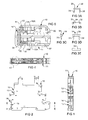
- Figures 1 and 2 show front and side views of pair of relay sockets 10, 11, electrically joined together via jumpers 12-15 and Figures 3A-E show details of jumper 14 (jumpers 12, 13 and 15 may be substantially identical).
- a cross sectional view along line X-X in Figure 2 is shown in Figure 4 with detail 40 in Figure 4 being shown in Figure 5 .
- jumper 14 includes a U-shaped body 30 made of a conducting material such as copper alloy.
- Jumper body 30 includes legs 31, 32 joined via web portion 33.
- Web portion 33 is covered via a housing 34 made of an electrically insulating material such as plastics.
- suitable plastics for the insulating material include PBT (Polybutylene terephthalate) or PA66 (Polyamide or Nylon 66).
- Jumper body 30 may be formed by stamping from a sheet of conducting material such as copper alloy sheet or it may be formed from copper alloy wire in any suitable manner and by any suitable means.
- Housing 34 may be formed over web portion 33 in any suitable manner and by any suitable means such as injection molding or the like.
- leg 31 of jumper 14 is inserted in recess 50 in front face 51 of relay socket 10 and engages contacts 52A, 52B associated with relay socket 10.
- Leg 32 of jumper 14 is inserted in recess 53 in front face 54 of relay socket 11 and engages contacts 55A, 55B associated with relay socket 11.
- Jumper 14 is adapted to electrically connect contacts 52A, 52B associated with relay socket 10 with contacts 55A, 55B associated with relay socket 11.
- Contacts 52A, 52B are electrically connected to PCB 56 associated with relay socket 10 and contacts 55A, 55B are electrically connected to PCB 57 associated with relay socket 11.
- When jumper 14 engages contacts 52, 55 electrical communication may be facilitated between PCB 56 in relay socket 10 and PCB 57 in relay socket 11.
- Jumper 15 performs a similar role to jumper 14 since its contacts (not shown) may be arranged to be electrically parallel with contacts 52, 55 respectively.
- One jumper of jumper pair 14, 15 may be electrically redundant when two relay sockets are electrically connected together as shown in Figure 1 .
- Similar comments apply to jumper pair 12, 13 wherein one jumper (12 or 13) may be electrically redundant when two relay sockets are electrically connected together as shown in Figure 1 .
- jumper pair 12,13 or 14,15 and their associated contacts may not be electrically redundant when three or more relay sockets are electrically connected together as described below with reference to Figures 6-7 .
- Figures 6A and 6B show front and perspective views of three relay sockets 10, 11, 60 electrically connected together via jumpers 12-15.
- jumpers 12-15 are staggered such that jumpers 12, 14 connect relay sockets 10, 11 and jumpers 13, 15 connect relay sockets 11, 60.
- jumper pairs 12, 13 and 14, 15 respectively may not be electrically redundant notwithstanding that each jumper pair 12, 13 and 14, 15 may engage contacts that internally may be electrically parallel or connected together.
- Figures 7A and 7B show front and perspective views of four relay sockets 10, 11, 60, 70 electrically joined together via jumpers 12-15, 71, 72.
- the jumpers are again staggered such that jumpers 12, 14 connect relay sockets 10, 11, jumpers 13, 15 connect relay sockets 11, 60 and jumpers 71, 72 connect relay sockets 60, 70.
- Jumper pairs 12, 13; 14, 15; 13, 71; 15, 72 also may not be electrically redundant notwithstanding that jumper triplets 12, 13, 71 and 14, 15, 72 may engage contacts that internally may be electrically parallel or connected together.
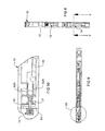
- Figure 8 shows the front face 51 of relay socket 10 with jumpers 12, 14 retained in relay socket 10 in a storage position.
- the legs of jumpers 12, 14 are retained in respective recesses formed in front face 51.
- a cross sectional view along line Y-Y in Figure 8 is shown in Figure 9 with detail 90 in Figure 9 being shown in Figure 10 .
- Figure 10 shows leg 31 of jumper 14 inserted in recess 50 in front face 51 of relay socket 10.
- Leg 31 is shown engaging contacts 52A, 52B although such contact may be electrically redundant in a storage position.
- Leg 32 of jumper 14 is inserted in a second recess (not shown) in relay socket 10.
- the second recess may be positioned along a line that extends substantially parallel to front face 51 of relay socket 10.
- the second recess in relay socket 10 may be positioned substantially vertically below recess 50. Spacing between recess 50 and the second recess may be selected such that it is substantially the same as the spacing between legs 31, 32.
- the position of the second recess in relay socket 10 may correspond to a recess associated with jumper 15 shown in Figure 1 .
- Figure 11 shows wide body relay sockets 110, 111 positioned side by side prior to being electrically connected together via one or more connecting jumpers 112-115.
- Connecting jumpers 112-115 are shown in storage positions in association with relay sockets 110, 111.
- Each connecting jumper 112-115 may be similar in construction to connecting jumper 14 as described with reference to Figure 3 .
- the legs of connecting jumper 112 are retained in recesses 116, 117 of relay socket 110 and the legs of connecting jumper 113 are retained in recesses 118, 119 of relay socket 110.
- the legs of connecting jumper 114 are retained in recesses 120, 121 of relay socket 111 and the legs of connecting jumper 115 are retained in recesses 122, 123 of relay socket 111.
- Each recess 117, 119, 121, 123 and 124-127 includes an electrical contact while each recess 116, 118 120, 122 may be a blank recess that does not include an electrical contact.
- the electrical contacts (not shown) associated with recesses 119, 123, 125, 127 may comprise positive polarity contacts.
- the electrical contacts (not shown) associated with recesses 117, 121, 124, 126 may comprise negative polarity contacts.
- Spacing between recess pairs 116, 117; 118, 119; 120, 121; and 122, 123 may be selected such that it is substantially the same as the spacing between legs 31,32 and/or recess pairs 123, 125 and 121, 124 when relay sockets 110,111 are positioned side by side.
- Figure 12 shows two wide body relay sockets 110, 111 electrically connected together via connecting jumpers 112, 113 and Figure 13 shows three wide body relay sockets 110, 111, 130 electrically connected together via connecting jumpers 112-115.
Landscapes
- Physics & Mathematics (AREA)
- Electromagnetism (AREA)
- Coupling Device And Connection With Printed Circuit (AREA)
- Connections Arranged To Contact A Plurality Of Conductors (AREA)
- Connector Housings Or Holding Contact Members (AREA)
- Connection Or Junction Boxes (AREA)
Abstract
Description
- The present invention relates to a modular electrical assembly such as a relay, circuit breaker, residual current device (RCD) or other switch gear assembly that may be electrically connected to at least one other modular electrical assembly in use. In particular the invention relates to a modular electrical assembly and structure for storing a connecting jumper associated with the modular assembly.
- Prior art electrical assemblies such as relays are typically connected via wires that are used as links between the relays. The process of installing relays using wires is time consuming and labour intensive. Also the quality of the connections may vary depending on the skill of the installer.
- Prior art electrical assemblies are sometimes joined via jumper strips that must be purchased separately as an accessory. The jumper strips may have 20 or more contacts that typically have to be cut to suit an installation resulting in wastage of jumper strips and leaving an exposed cut metal edge that may give rise to safety concerns.
- The present invention may provide a modular electrical assembly and structure for storing a connecting jumper that alleviates the disadvantages of the prior art or at least provides the consumer with a choice.
- According to one aspect of the present invention there is provided a modular electrical assembly adapted to be electrically connected to at least one other modular electrical assembly by means of a connecting jumper, wherein said assembly includes a storage structure for storing said connecting jumper associated with said modular assembly prior to use.
- The modular assembly may include electrical switchgear such as a relay, relay socket, circuit breaker or residual current device (RCD).
- The or each connecting jumper may include a generally U-shaped body made of a conducting material and may include two legs joined via a web. The conducting body may comprise a copper alloy or other material that has good electrical conductivity. The conducting web may be covered by an electrically insulated housing. The electrically insulated housing may comprise PBT (Polybutylene terephthalate) or PA66 (Polyamide or Nylon 66).
- The storage structure may include one or more recesses in the assembly for retaining at least a part of the connecting jumper such as a leg. The or each recess may include an electrical contact or it may be a blank recess. The or each electrical contact may be adapted to be connectable to an electrical contact of at least one other modular assembly.
- The storage structure may be adapted to store the connecting jumper in a front face of the assembly. The storage structure may be arranged in the front face of the assembly such that the web of the jumper extends substantially parallel to a long side of the front face. In some embodiments the storage structure may be arranged such that the web of the jumper extends at an angle relative to the long side of the front face.
- In one form the front face of the assembly may include two recesses for receiving legs of a connecting jumper. The two recesses may be positioned along a line that extends substantially parallel to the front face of the assembly.
- According to another aspect of the present invention there is provided a method of electrically connecting a modular electrical assembly to at least one other modular electrical assembly including connecting said assemblies by means of a connecting jumper, wherein said assembly includes a storage structure for storing said connecting jumper associated with said modular assembly prior to use.
- A preferred embodiment of the present invention will now be described with reference to the accompanying drawings wherein:
-
Figure 1 shows a front view of a pair of relay sockets connected in use; -
Figure 2 shows a side view of the relay sockets inFigure 1 ; -
Figures 3A to 3E show views of a connecting jumper according to one embodiment of the present invention; -
Figure 4 shows a cross sectional view along X-X inFigure 2 ; -
Figure 5 showsdetail 40 inFigure 4 ; -
Figures 6A and 6B show front and perspective views of three relay sockets connected in use; -
Figures 7A and 7B show front and perspective views of four relay sockets connected in use; -
Figure 8 shows a front view of a relay socket with jumpers in a storage position; -
Figure 9 shows a cross sectional view along line Y-Y inFigure 8 ; -
Figure 10 showsdetail 90 inFigure 9 ; -
Figure 11 shows a pair of wide body relay sockets before connection; -
Figure 12 shows a pair of wide body relay sockets after connection; and -
Figure 13 shows three wide body relay sockets after connection. - A preferred embodiment of the present invention is described below with reference to slim body relay sockets being relay sockets that are approximately 6.2mm wide. Nevertheless it will be appreciated that the present invention is also applicable to relay sockets and other modular electrical assemblies being other than slim body modular assemblies such as wide body relay sockets and wide body modular electrical assemblies.
-
Figures 1 and 2 show front and side views of pair ofrelay sockets Figures 3A-E show details of jumper 14 (jumpers Figure 2 is shown inFigure 4 withdetail 40 inFigure 4 being shown inFigure 5 . - Referring firstly to
Figures 3A to 3E ,jumper 14 includes aU-shaped body 30 made of a conducting material such as copper alloy.Jumper body 30 includeslegs web portion 33.Web portion 33 is covered via ahousing 34 made of an electrically insulating material such as plastics. Examples of suitable plastics for the insulating material include PBT (Polybutylene terephthalate) or PA66 (Polyamide or Nylon 66). -
Jumper body 30 may be formed by stamping from a sheet of conducting material such as copper alloy sheet or it may be formed from copper alloy wire in any suitable manner and by any suitable means.Housing 34 may be formed overweb portion 33 in any suitable manner and by any suitable means such as injection molding or the like. - Referring to
Figures 4 and 5 ,leg 31 ofjumper 14 is inserted inrecess 50 infront face 51 ofrelay socket 10 and engagescontacts relay socket 10.Leg 32 ofjumper 14 is inserted inrecess 53 infront face 54 ofrelay socket 11 and engagescontacts relay socket 11. Jumper 14 is adapted to electrically connectcontacts relay socket 10 withcontacts relay socket 11.Contacts PCB 56 associated withrelay socket 10 andcontacts relay socket 11. Whenjumper 14 engages contacts 52, 55 electrical communication may be facilitated between PCB 56 inrelay socket 10 and PCB 57 inrelay socket 11. - Jumper 15 performs a similar role to jumper 14 since its contacts (not shown) may be arranged to be electrically parallel with contacts 52, 55 respectively. One jumper of
jumper pair Figure 1 . Similar comments apply tojumper pair Figure 1 . Howeverjumper pair Figures 6-7 . -
Figures 6A and 6B show front and perspective views of threerelay sockets Figure 1 jumpers 12-15 are staggered such thatjumpers relay sockets jumpers relay sockets Figure 1 jumper pairs jumper pair -
Figures 7A and 7B show front and perspective views of fourrelay sockets jumpers relay sockets jumpers relay sockets jumpers relay sockets -
Figure 8 shows thefront face 51 ofrelay socket 10 withjumpers relay socket 10 in a storage position. The legs ofjumpers front face 51. A cross sectional view along line Y-Y inFigure 8 is shown inFigure 9 withdetail 90 inFigure 9 being shown inFigure 10 . -
Figure 10 showsleg 31 ofjumper 14 inserted inrecess 50 in front face 51 ofrelay socket 10.Leg 31 is shown engagingcontacts Leg 32 ofjumper 14 is inserted in a second recess (not shown) inrelay socket 10. The second recess may be positioned along a line that extends substantially parallel tofront face 51 ofrelay socket 10. In the storage position shown inFigure 8 the second recess inrelay socket 10 may be positioned substantially vertically belowrecess 50. Spacing betweenrecess 50 and the second recess may be selected such that it is substantially the same as the spacing betweenlegs relay socket 10 may correspond to a recess associated withjumper 15 shown inFigure 1 . -
Figure 11 shows widebody relay sockets relay sockets jumper 14 as described with reference toFigure 3 . - The legs of connecting
jumper 112 are retained inrecesses relay socket 110 and the legs of connectingjumper 113 are retained inrecesses relay socket 110. The legs of connectingjumper 114 are retained inrecesses relay socket 111 and the legs of connectingjumper 115 are retained inrecesses relay socket 111. - Each
recess recess recesses recesses - Spacing between recess pairs 116, 117; 118, 119; 120, 121; and 122, 123 may be selected such that it is substantially the same as the spacing between
legs -
Figure 12 shows two widebody relay sockets jumpers Figure 13 shows three widebody relay sockets - Advantages of a modular electrical assembly including structure for storing a connecting jumper according to the present invention include:
- 1. Less inventory since jumpers required to connect one modular electrical assembly such as a relay socket to another modular electrical assembly may be stored and purchased with the modular assembly.
- 2. Even if end users pay for two additional jumpers with each modular assembly (which they may not use) the extra cost may be offset because purchase of long jumper strips which must be cut to length and associated wastage may be avoided.
- 3. The issue of exposed metal after a jumper strip is cut may be avoided leading to improved safety in the use of jumpers with an insulated housing according to the present invention.
- 4. Accurate and consistent interconnection between modular assemblies may be ensured promoting product reliability and improving safety.
- Finally, it is to be understood that various alterations, modifications and/or additions may be introduced into the constructions and arrangements of parts previously described without departing from the spirit or ambit of the invention.
Claims (19)
- A modular electrical assembly adapted to be electrically connected to at least one other modular electrical assembly by means of a connecting jumper, wherein said assembly includes a storage structure for storing said connecting jumper associated with said modular assembly prior to use.
- A modular electrical assembly according to claim 1 wherein said assembly includes electrical switchgear such as a relay, a circuit breaker or a residual current device (RCD).
- A modular electrical assembly according to claim 1 wherein said connecting jumper comprises a generally U-shaped body made of a conducting material including two legs joined via a web, and wherein said web is covered by an electrically insulated housing.
- A modular electrical assembly according to claim 3 wherein said conducting body comprises copper alloy.
- A modular electrical assembly according to claim 1 wherein said storage structure includes a recess in said assembly for retaining at least a part of said connecting jumper.
- A modular electrical assembly according to claim 5 wherein said recess includes an electrical contact that is connectable to an electrical contact of said one other modular assembly.
- A modular electrical assembly according to claim 3 wherein said storage structure is adapted to store said connecting jumper in a front face of said assembly such that said web extends substantially parallel to a long side of said front face.
- A modular electrical assembly according to claim 3 wherein said storage structure includes two recesses in said assembly for receiving the legs of said connecting jumper.
- A modular electrical assembly according to claim 8 wherein said two recesses are positioned along a line that extends substantially parallel to a front face of said assembly.
- In combination a modular electrical assembly according to claim 1 and including at least one connecting jumper stored in association with said assembly prior to use.
- A method of electrically connecting a modular electrical assembly to at least one other modular electrical assembly including connecting said assemblies by means of a connecting jumper, wherein said assembly includes a storage structure for storing said connecting jumper associated with said modular assembly prior to use.
- A method according to claim 11 wherein said modular assembly includes electrical switchgear such as a relay, a circuit breaker or a residual current device (RCD).
- A method according to claim 11 wherein said connecting jumper comprises a generally U-shaped body made of a conducting material including two legs joined via a web, and wherein said web is covered by an electrically insulated housing.
- A method according to claim 13 wherein said conducting body comprises copper alloy.
- A method according to claim 11 wherein said storage structure includes a recess in said assembly for retaining at least a part of said connecting jumper.
- A method according to claim 15 wherein said recess includes an electrical contact and including connecting said electrical contact to an electrical contact of said one other modular assembly by means of said connecting jumper.
- A method according to claim 13 wherein said storage structure is adapted to store said connecting jumper in a front face of said assembly such that said web extends substantially parallel to a long side of said front face.
- A method according to claim 13 wherein said storage structure includes two recesses in said assembly for receiving respective legs of said connecting jumper.
- A method according to claim 13 wherein said two recesses are positioned along a line that extends substantially parallel to a front face of said assembly.
Applications Claiming Priority (1)
| Application Number | Priority Date | Filing Date | Title |
|---|---|---|---|
| SG2010092807A SG182014A1 (en) | 2010-12-14 | 2010-12-14 | Modular electrical assembly with jumper storage |
Publications (3)
| Publication Number | Publication Date |
|---|---|
| EP2466691A2 true EP2466691A2 (en) | 2012-06-20 |
| EP2466691A3 EP2466691A3 (en) | 2013-06-19 |
| EP2466691B1 EP2466691B1 (en) | 2017-02-15 |
Family
ID=45554413
Family Applications (1)
| Application Number | Title | Priority Date | Filing Date |
|---|---|---|---|
| EP11009723.5A Active EP2466691B1 (en) | 2010-12-14 | 2011-12-09 | Modular electrical assembly with jumper storage |
Country Status (4)
| Country | Link |
|---|---|
| US (1) | US8647157B2 (en) |
| EP (1) | EP2466691B1 (en) |
| CN (1) | CN102543596B (en) |
| SG (1) | SG182014A1 (en) |
Families Citing this family (13)
| Publication number | Priority date | Publication date | Assignee | Title |
|---|---|---|---|---|
| DE102010009805B4 (en) * | 2010-03-01 | 2013-02-14 | Phoenix Contact Gmbh & Co. Kg | jumper |
| SG182014A1 (en) * | 2010-12-14 | 2012-07-30 | Schneider Electric South East Asia Hq Pte Ltd | Modular electrical assembly with jumper storage |
| ITMI20120457A1 (en) * | 2012-03-23 | 2013-09-24 | Morsettitalia Spa | HOUSING FOR ELECTRIC / ELECTRONIC CIRCUITS EQUIPPED WITH LOCATIONS AND RELATED CONTACT ELEMENTS FOR ELECTRICAL WIRING CONNECTORS |
| DE102012206600A1 (en) * | 2012-04-20 | 2013-10-24 | Wöhner GmbH & Co. KG Elektrotechnische Systeme | DIN rail adapter |
| USD717734S1 (en) * | 2012-06-13 | 2014-11-18 | Phoenix Contact Gmbh & Co. Kg | Electrical connector comprising a plurality of modular terminal blocks |
| USD700898S1 (en) * | 2012-07-31 | 2014-03-11 | Phoenix Contact Gmbh & Co. Kg | Socket module for an electronic relay |
| DE102012107264A1 (en) * | 2012-08-08 | 2014-02-13 | Phoenix Contact Gmbh & Co. Kg | connection module |
| CN103325586B (en) * | 2013-07-01 | 2016-08-10 | 华为技术有限公司 | A kind of breaker assembly and single P chopper |
| DE202014009245U1 (en) * | 2014-11-21 | 2016-02-24 | Ellenberger & Poensgen Gmbh | Switchgear and switching device arrangement |
| PL3054533T3 (en) * | 2015-02-05 | 2020-06-29 | Morsettitalia S.P.A. | Base terminal block and auxiliary terminal block for switchboards and two-tier terminal block assembly comprising base terminal block and auxiliary terminal block |
| USD901400S1 (en) * | 2017-03-07 | 2020-11-10 | Phoenix Contact Gmbh & Co. Kg | Electrical connector |
| JP1623418S (en) * | 2018-03-14 | 2019-02-04 | ||
| USD951881S1 (en) * | 2020-02-05 | 2022-05-17 | Dehn Se | Surge protection device |
Family Cites Families (10)
| Publication number | Priority date | Publication date | Assignee | Title |
|---|---|---|---|---|
| FR2662549B1 (en) * | 1990-05-28 | 1994-05-13 | Applications Electro Mecaniques | INTERCONNECTION DEVICE FOR ELECTRICAL CONNECTION RULE OR THE LIKE. |
| US5669788A (en) * | 1996-09-18 | 1997-09-23 | Allen-Bradley Company, Inc. | Screwless terminal block linking apparatus |
| DE29719177U1 (en) * | 1997-10-29 | 1997-12-04 | Weidmüller Interface GmbH & Co, 32760 Detmold | Terminal block arrangement |
| DE29917825U1 (en) * | 1999-10-09 | 2001-02-22 | Weidmüller Interface GmbH & Co, 32760 Detmold | Connection element with cross connection |
| DE102005040657A1 (en) * | 2005-08-26 | 2007-03-15 | Phoenix Contact Gmbh & Co. Kg | Electrical connection terminal |
| DE102008014179B4 (en) * | 2008-03-14 | 2012-08-02 | Phoenix Contact Gmbh & Co. Kg | Switching bridge and assembly consisting of at least two electrical terminal blocks and a jumper |
| DE102008014177A1 (en) * | 2008-03-14 | 2009-09-17 | Phoenix Contact Gmbh & Co. Kg | Terminal block and terminal block |
| PL2104193T3 (en) * | 2008-03-21 | 2015-03-31 | Bticino Spa | Rapid plug-in modular electrical equipment |
| DE202009014251U1 (en) * | 2009-10-21 | 2011-03-17 | Phoenix Contact Gmbh & Co. Kg | System for connecting electrical conductors with mutually different potentials as well as plug-in adapters for the system |
| SG182014A1 (en) * | 2010-12-14 | 2012-07-30 | Schneider Electric South East Asia Hq Pte Ltd | Modular electrical assembly with jumper storage |
-
2010
- 2010-12-14 SG SG2010092807A patent/SG182014A1/en unknown
-
2011
- 2011-12-08 CN CN201110405052.3A patent/CN102543596B/en active Active
- 2011-12-09 EP EP11009723.5A patent/EP2466691B1/en active Active
- 2011-12-13 US US13/324,128 patent/US8647157B2/en not_active Expired - Fee Related
Non-Patent Citations (1)
| Title |
|---|
| None |
Also Published As
| Publication number | Publication date |
|---|---|
| CN102543596B (en) | 2015-10-14 |
| CN102543596A (en) | 2012-07-04 |
| US20120149237A1 (en) | 2012-06-14 |
| SG182014A1 (en) | 2012-07-30 |
| EP2466691A3 (en) | 2013-06-19 |
| EP2466691B1 (en) | 2017-02-15 |
| US8647157B2 (en) | 2014-02-11 |
Similar Documents
| Publication | Publication Date | Title |
|---|---|---|
| EP2466691B1 (en) | Modular electrical assembly with jumper storage | |
| US7192316B1 (en) | Electrical connecting terminal | |
| CN101114737B (en) | Terminal strip with encoding device | |
| JP5730445B2 (en) | Electrical series terminals and series terminal blocks | |
| US20120329317A1 (en) | Connection structure of crimping terminal to electrical wire | |
| US8573988B2 (en) | Mounting structure of connector for circuit board | |
| EP1876674B1 (en) | Insulated jumper in particular for terminal blocks of switchboards | |
| CN102474019A (en) | Connecting device and shunt terminal | |
| EA034283B1 (en) | Electric terminal block | |
| KR20150048195A (en) | Connection terminal | |
| JP2004282908A (en) | Busbar connection structure of electrical junction box and busbar connection method | |
| EP3151349B1 (en) | Prong-less neutral connector assemblies, circuit breakers including prong-less neutral connector, panel boards with flexible neutral bars, and neutral connection methods | |
| JP4355742B2 (en) | Short-circuit plate | |
| CN102844939A (en) | Connection apparatus with variable electrical connection between conductor terminals | |
| WO2015099072A1 (en) | Electrical-wire connection structure | |
| US20110232960A1 (en) | Component-equipped-holder mounting structure | |
| JP2021099905A (en) | Crimp connection terminal | |
| JP6913278B2 (en) | Connection structure of plate-shaped conductive members and plate-shaped conductive path | |
| KR101564777B1 (en) | Board to board connector | |
| CN104979141B (en) | Breaker | |
| JP6210736B2 (en) | Fuse unit | |
| JP2002281643A (en) | Bus bar structure | |
| CN219998532U (en) | Short circuit structure and intelligent terminal access device | |
| KR200457362Y1 (en) | Wiring Kit | |
| JP3702758B2 (en) | Electrical junction box |
Legal Events
| Date | Code | Title | Description |
|---|---|---|---|
| PUAI | Public reference made under article 153(3) epc to a published international application that has entered the european phase |
Free format text: ORIGINAL CODE: 0009012 |
|
| AK | Designated contracting states |
Kind code of ref document: A2 Designated state(s): AL AT BE BG CH CY CZ DE DK EE ES FI FR GB GR HR HU IE IS IT LI LT LU LV MC MK MT NL NO PL PT RO RS SE SI SK SM TR |
|
| AX | Request for extension of the european patent |
Extension state: BA ME |
|
| PUAL | Search report despatched |
Free format text: ORIGINAL CODE: 0009013 |
|
| AK | Designated contracting states |
Kind code of ref document: A3 Designated state(s): AL AT BE BG CH CY CZ DE DK EE ES FI FR GB GR HR HU IE IS IT LI LT LU LV MC MK MT NL NO PL PT RO RS SE SI SK SM TR |
|
| AX | Request for extension of the european patent |
Extension state: BA ME |
|
| RIC1 | Information provided on ipc code assigned before grant |
Ipc: H01H 71/08 20060101ALI20130513BHEP Ipc: H01R 9/26 20060101AFI20130513BHEP Ipc: H01H 71/02 20060101ALI20130513BHEP Ipc: H01H 50/04 20060101ALI20130513BHEP |
|
| 17P | Request for examination filed |
Effective date: 20131212 |
|
| RBV | Designated contracting states (corrected) |
Designated state(s): AL AT BE BG CH CY CZ DE DK EE ES FI FR GB GR HR HU IE IS IT LI LT LU LV MC MK MT NL NO PL PT RO RS SE SI SK SM TR |
|
| 17Q | First examination report despatched |
Effective date: 20160127 |
|
| GRAP | Despatch of communication of intention to grant a patent |
Free format text: ORIGINAL CODE: EPIDOSNIGR1 |
|
| INTG | Intention to grant announced |
Effective date: 20160824 |
|
| GRAS | Grant fee paid |
Free format text: ORIGINAL CODE: EPIDOSNIGR3 |
|
| GRAA | (expected) grant |
Free format text: ORIGINAL CODE: 0009210 |
|
| AK | Designated contracting states |
Kind code of ref document: B1 Designated state(s): AL AT BE BG CH CY CZ DE DK EE ES FI FR GB GR HR HU IE IS IT LI LT LU LV MC MK MT NL NO PL PT RO RS SE SI SK SM TR |
|
| REG | Reference to a national code |
Ref country code: CH Ref legal event code: EP Ref country code: GB Ref legal event code: FG4D |
|
| REG | Reference to a national code |
Ref country code: IE Ref legal event code: FG4D |
|
| REG | Reference to a national code |
Ref country code: AT Ref legal event code: REF Ref document number: 868368 Country of ref document: AT Kind code of ref document: T Effective date: 20170315 |
|
| REG | Reference to a national code |
Ref country code: DE Ref legal event code: R096 Ref document number: 602011034994 Country of ref document: DE |
|
| REG | Reference to a national code |
Ref country code: NL Ref legal event code: MP Effective date: 20170215 |
|
| REG | Reference to a national code |
Ref country code: DE Ref legal event code: R082 Ref document number: 602011034994 Country of ref document: DE Representative=s name: MANITZ FINSTERWALD PATENT- UND RECHTSANWALTSPA, DE Ref country code: DE Ref legal event code: R082 Ref document number: 602011034994 Country of ref document: DE Representative=s name: MANITZ FINSTERWALD PATENTANWAELTE PARTMBB, DE Ref country code: DE Ref legal event code: R081 Ref document number: 602011034994 Country of ref document: DE Owner name: SCHNEIDER ELECTRIC LOGISTICS ASIA PTE LTD., SG Free format text: FORMER OWNER: SCHNEIDER ELECTRIC INDUSTRIES SAS, RUEIL-MALMAISON, FR |
|
| REG | Reference to a national code |
Ref country code: LT Ref legal event code: MG4D |
|
| REG | Reference to a national code |
Ref country code: ES Ref legal event code: FG2A Ref document number: 2623832 Country of ref document: ES Kind code of ref document: T3 Effective date: 20170712 |
|
| REG | Reference to a national code |
Ref country code: AT Ref legal event code: MK05 Ref document number: 868368 Country of ref document: AT Kind code of ref document: T Effective date: 20170215 |
|
| PG25 | Lapsed in a contracting state [announced via postgrant information from national office to epo] |
Ref country code: HR Free format text: LAPSE BECAUSE OF FAILURE TO SUBMIT A TRANSLATION OF THE DESCRIPTION OR TO PAY THE FEE WITHIN THE PRESCRIBED TIME-LIMIT Effective date: 20170215 Ref country code: FI Free format text: LAPSE BECAUSE OF FAILURE TO SUBMIT A TRANSLATION OF THE DESCRIPTION OR TO PAY THE FEE WITHIN THE PRESCRIBED TIME-LIMIT Effective date: 20170215 Ref country code: NO Free format text: LAPSE BECAUSE OF FAILURE TO SUBMIT A TRANSLATION OF THE DESCRIPTION OR TO PAY THE FEE WITHIN THE PRESCRIBED TIME-LIMIT Effective date: 20170515 Ref country code: GR Free format text: LAPSE BECAUSE OF FAILURE TO SUBMIT A TRANSLATION OF THE DESCRIPTION OR TO PAY THE FEE WITHIN THE PRESCRIBED TIME-LIMIT Effective date: 20170516 Ref country code: LT Free format text: LAPSE BECAUSE OF FAILURE TO SUBMIT A TRANSLATION OF THE DESCRIPTION OR TO PAY THE FEE WITHIN THE PRESCRIBED TIME-LIMIT Effective date: 20170215 |
|
| RAP2 | Party data changed (patent owner data changed or rights of a patent transferred) |
Owner name: SCHNEIDER ELECTRIC LOGISTICS ASIA PTE LTD. |
|
| PG25 | Lapsed in a contracting state [announced via postgrant information from national office to epo] |
Ref country code: RS Free format text: LAPSE BECAUSE OF FAILURE TO SUBMIT A TRANSLATION OF THE DESCRIPTION OR TO PAY THE FEE WITHIN THE PRESCRIBED TIME-LIMIT Effective date: 20170215 Ref country code: AT Free format text: LAPSE BECAUSE OF FAILURE TO SUBMIT A TRANSLATION OF THE DESCRIPTION OR TO PAY THE FEE WITHIN THE PRESCRIBED TIME-LIMIT Effective date: 20170215 Ref country code: LV Free format text: LAPSE BECAUSE OF FAILURE TO SUBMIT A TRANSLATION OF THE DESCRIPTION OR TO PAY THE FEE WITHIN THE PRESCRIBED TIME-LIMIT Effective date: 20170215 Ref country code: BG Free format text: LAPSE BECAUSE OF FAILURE TO SUBMIT A TRANSLATION OF THE DESCRIPTION OR TO PAY THE FEE WITHIN THE PRESCRIBED TIME-LIMIT Effective date: 20170515 Ref country code: NL Free format text: LAPSE BECAUSE OF FAILURE TO SUBMIT A TRANSLATION OF THE DESCRIPTION OR TO PAY THE FEE WITHIN THE PRESCRIBED TIME-LIMIT Effective date: 20170215 Ref country code: PT Free format text: LAPSE BECAUSE OF FAILURE TO SUBMIT A TRANSLATION OF THE DESCRIPTION OR TO PAY THE FEE WITHIN THE PRESCRIBED TIME-LIMIT Effective date: 20170615 Ref country code: SE Free format text: LAPSE BECAUSE OF FAILURE TO SUBMIT A TRANSLATION OF THE DESCRIPTION OR TO PAY THE FEE WITHIN THE PRESCRIBED TIME-LIMIT Effective date: 20170215 |
|
| REG | Reference to a national code |
Ref country code: GB Ref legal event code: 732E Free format text: REGISTERED BETWEEN 20170810 AND 20170816 |
|
| PG25 | Lapsed in a contracting state [announced via postgrant information from national office to epo] |
Ref country code: EE Free format text: LAPSE BECAUSE OF FAILURE TO SUBMIT A TRANSLATION OF THE DESCRIPTION OR TO PAY THE FEE WITHIN THE PRESCRIBED TIME-LIMIT Effective date: 20170215 Ref country code: RO Free format text: LAPSE BECAUSE OF FAILURE TO SUBMIT A TRANSLATION OF THE DESCRIPTION OR TO PAY THE FEE WITHIN THE PRESCRIBED TIME-LIMIT Effective date: 20170215 Ref country code: CZ Free format text: LAPSE BECAUSE OF FAILURE TO SUBMIT A TRANSLATION OF THE DESCRIPTION OR TO PAY THE FEE WITHIN THE PRESCRIBED TIME-LIMIT Effective date: 20170215 Ref country code: SK Free format text: LAPSE BECAUSE OF FAILURE TO SUBMIT A TRANSLATION OF THE DESCRIPTION OR TO PAY THE FEE WITHIN THE PRESCRIBED TIME-LIMIT Effective date: 20170215 |
|
| REG | Reference to a national code |
Ref country code: DE Ref legal event code: R097 Ref document number: 602011034994 Country of ref document: DE |
|
| PG25 | Lapsed in a contracting state [announced via postgrant information from national office to epo] |
Ref country code: DK Free format text: LAPSE BECAUSE OF FAILURE TO SUBMIT A TRANSLATION OF THE DESCRIPTION OR TO PAY THE FEE WITHIN THE PRESCRIBED TIME-LIMIT Effective date: 20170215 Ref country code: PL Free format text: LAPSE BECAUSE OF FAILURE TO SUBMIT A TRANSLATION OF THE DESCRIPTION OR TO PAY THE FEE WITHIN THE PRESCRIBED TIME-LIMIT Effective date: 20170215 Ref country code: SM Free format text: LAPSE BECAUSE OF FAILURE TO SUBMIT A TRANSLATION OF THE DESCRIPTION OR TO PAY THE FEE WITHIN THE PRESCRIBED TIME-LIMIT Effective date: 20170215 |
|
| REG | Reference to a national code |
Ref country code: FR Ref legal event code: PLFP Year of fee payment: 7 |
|
| PLBE | No opposition filed within time limit |
Free format text: ORIGINAL CODE: 0009261 |
|
| STAA | Information on the status of an ep patent application or granted ep patent |
Free format text: STATUS: NO OPPOSITION FILED WITHIN TIME LIMIT |
|
| REG | Reference to a national code |
Ref country code: FR Ref legal event code: TP Owner name: SCHNEIDER ELECTRIC INDUSTRIES SAS, FR Effective date: 20171212 |
|
| 26N | No opposition filed |
Effective date: 20171116 |
|
| PG25 | Lapsed in a contracting state [announced via postgrant information from national office to epo] |
Ref country code: SI Free format text: LAPSE BECAUSE OF FAILURE TO SUBMIT A TRANSLATION OF THE DESCRIPTION OR TO PAY THE FEE WITHIN THE PRESCRIBED TIME-LIMIT Effective date: 20170215 |
|
| REG | Reference to a national code |
Ref country code: CH Ref legal event code: PL |
|
| REG | Reference to a national code |
Ref country code: IE Ref legal event code: MM4A |
|
| PG25 | Lapsed in a contracting state [announced via postgrant information from national office to epo] |
Ref country code: MT Free format text: LAPSE BECAUSE OF NON-PAYMENT OF DUE FEES Effective date: 20171209 Ref country code: LU Free format text: LAPSE BECAUSE OF NON-PAYMENT OF DUE FEES Effective date: 20171209 |
|
| REG | Reference to a national code |
Ref country code: BE Ref legal event code: MM Effective date: 20171231 |
|
| PG25 | Lapsed in a contracting state [announced via postgrant information from national office to epo] |
Ref country code: IE Free format text: LAPSE BECAUSE OF NON-PAYMENT OF DUE FEES Effective date: 20171209 |
|
| PG25 | Lapsed in a contracting state [announced via postgrant information from national office to epo] |
Ref country code: BE Free format text: LAPSE BECAUSE OF NON-PAYMENT OF DUE FEES Effective date: 20171231 Ref country code: CH Free format text: LAPSE BECAUSE OF NON-PAYMENT OF DUE FEES Effective date: 20171231 Ref country code: LI Free format text: LAPSE BECAUSE OF NON-PAYMENT OF DUE FEES Effective date: 20171231 |
|
| PG25 | Lapsed in a contracting state [announced via postgrant information from national office to epo] |
Ref country code: HU Free format text: LAPSE BECAUSE OF FAILURE TO SUBMIT A TRANSLATION OF THE DESCRIPTION OR TO PAY THE FEE WITHIN THE PRESCRIBED TIME-LIMIT; INVALID AB INITIO Effective date: 20111209 Ref country code: MC Free format text: LAPSE BECAUSE OF FAILURE TO SUBMIT A TRANSLATION OF THE DESCRIPTION OR TO PAY THE FEE WITHIN THE PRESCRIBED TIME-LIMIT Effective date: 20170215 |
|
| PG25 | Lapsed in a contracting state [announced via postgrant information from national office to epo] |
Ref country code: CY Free format text: LAPSE BECAUSE OF NON-PAYMENT OF DUE FEES Effective date: 20170215 |
|
| PG25 | Lapsed in a contracting state [announced via postgrant information from national office to epo] |
Ref country code: MK Free format text: LAPSE BECAUSE OF FAILURE TO SUBMIT A TRANSLATION OF THE DESCRIPTION OR TO PAY THE FEE WITHIN THE PRESCRIBED TIME-LIMIT Effective date: 20170215 |
|
| PG25 | Lapsed in a contracting state [announced via postgrant information from national office to epo] |
Ref country code: TR Free format text: LAPSE BECAUSE OF FAILURE TO SUBMIT A TRANSLATION OF THE DESCRIPTION OR TO PAY THE FEE WITHIN THE PRESCRIBED TIME-LIMIT Effective date: 20170215 |
|
| PG25 | Lapsed in a contracting state [announced via postgrant information from national office to epo] |
Ref country code: AL Free format text: LAPSE BECAUSE OF FAILURE TO SUBMIT A TRANSLATION OF THE DESCRIPTION OR TO PAY THE FEE WITHIN THE PRESCRIBED TIME-LIMIT Effective date: 20170215 Ref country code: IS Free format text: LAPSE BECAUSE OF FAILURE TO SUBMIT A TRANSLATION OF THE DESCRIPTION OR TO PAY THE FEE WITHIN THE PRESCRIBED TIME-LIMIT Effective date: 20170615 |
|
| PGFP | Annual fee paid to national office [announced via postgrant information from national office to epo] |
Ref country code: GB Payment date: 20251219 Year of fee payment: 15 |
|
| PGFP | Annual fee paid to national office [announced via postgrant information from national office to epo] |
Ref country code: IT Payment date: 20251223 Year of fee payment: 15 |
|
| PGFP | Annual fee paid to national office [announced via postgrant information from national office to epo] |
Ref country code: FR Payment date: 20251222 Year of fee payment: 15 |
|
| PGFP | Annual fee paid to national office [announced via postgrant information from national office to epo] |
Ref country code: ES Payment date: 20260130 Year of fee payment: 15 |
|
| PGFP | Annual fee paid to national office [announced via postgrant information from national office to epo] |
Ref country code: DE Payment date: 20260224 Year of fee payment: 15 |