EP2466385A1 - Image forming apparatus and auto color registration method of the same - Google Patents
Image forming apparatus and auto color registration method of the same Download PDFInfo
- Publication number
- EP2466385A1 EP2466385A1 EP11181542A EP11181542A EP2466385A1 EP 2466385 A1 EP2466385 A1 EP 2466385A1 EP 11181542 A EP11181542 A EP 11181542A EP 11181542 A EP11181542 A EP 11181542A EP 2466385 A1 EP2466385 A1 EP 2466385A1
- Authority
- EP
- European Patent Office
- Prior art keywords
- transfer belt
- detector
- acr
- transfer
- forming apparatus
- Prior art date
- Legal status (The legal status is an assumption and is not a legal conclusion. Google has not performed a legal analysis and makes no representation as to the accuracy of the status listed.)
- Granted
Links
Images


Classifications
-
- G—PHYSICS
- G03—PHOTOGRAPHY; CINEMATOGRAPHY; ANALOGOUS TECHNIQUES USING WAVES OTHER THAN OPTICAL WAVES; ELECTROGRAPHY; HOLOGRAPHY
- G03G—ELECTROGRAPHY; ELECTROPHOTOGRAPHY; MAGNETOGRAPHY
- G03G15/00—Apparatus for electrographic processes using a charge pattern
- G03G15/01—Apparatus for electrographic processes using a charge pattern for producing multicoloured copies
- G03G15/0105—Details of unit
- G03G15/0131—Details of unit for transferring a pattern to a second base
-
- G—PHYSICS
- G03—PHOTOGRAPHY; CINEMATOGRAPHY; ANALOGOUS TECHNIQUES USING WAVES OTHER THAN OPTICAL WAVES; ELECTROGRAPHY; HOLOGRAPHY
- G03G—ELECTROGRAPHY; ELECTROPHOTOGRAPHY; MAGNETOGRAPHY
- G03G15/00—Apparatus for electrographic processes using a charge pattern
- G03G15/50—Machine control of apparatus for electrographic processes using a charge pattern, e.g. regulating differents parts of the machine, multimode copiers, microprocessor control
- G03G15/5054—Machine control of apparatus for electrographic processes using a charge pattern, e.g. regulating differents parts of the machine, multimode copiers, microprocessor control by measuring the characteristics of an intermediate image carrying member or the characteristics of an image on an intermediate image carrying member, e.g. intermediate transfer belt or drum, conveyor belt
- G03G15/5058—Machine control of apparatus for electrographic processes using a charge pattern, e.g. regulating differents parts of the machine, multimode copiers, microprocessor control by measuring the characteristics of an intermediate image carrying member or the characteristics of an image on an intermediate image carrying member, e.g. intermediate transfer belt or drum, conveyor belt using a test patch
-
- G—PHYSICS
- G03—PHOTOGRAPHY; CINEMATOGRAPHY; ANALOGOUS TECHNIQUES USING WAVES OTHER THAN OPTICAL WAVES; ELECTROGRAPHY; HOLOGRAPHY
- G03G—ELECTROGRAPHY; ELECTROPHOTOGRAPHY; MAGNETOGRAPHY
- G03G15/00—Apparatus for electrographic processes using a charge pattern
- G03G15/14—Apparatus for electrographic processes using a charge pattern for transferring a pattern to a second base
-
- G—PHYSICS
- G03—PHOTOGRAPHY; CINEMATOGRAPHY; ANALOGOUS TECHNIQUES USING WAVES OTHER THAN OPTICAL WAVES; ELECTROGRAPHY; HOLOGRAPHY
- G03G—ELECTROGRAPHY; ELECTROPHOTOGRAPHY; MAGNETOGRAPHY
- G03G15/00—Apparatus for electrographic processes using a charge pattern
- G03G15/14—Apparatus for electrographic processes using a charge pattern for transferring a pattern to a second base
- G03G15/16—Apparatus for electrographic processes using a charge pattern for transferring a pattern to a second base of a toner pattern, e.g. a powder pattern, e.g. magnetic transfer
- G03G15/1605—Apparatus for electrographic processes using a charge pattern for transferring a pattern to a second base of a toner pattern, e.g. a powder pattern, e.g. magnetic transfer using at least one intermediate support
- G03G15/161—Apparatus for electrographic processes using a charge pattern for transferring a pattern to a second base of a toner pattern, e.g. a powder pattern, e.g. magnetic transfer using at least one intermediate support with means for handling the intermediate support, e.g. heating, cleaning, coating with a transfer agent
-
- G—PHYSICS
- G03—PHOTOGRAPHY; CINEMATOGRAPHY; ANALOGOUS TECHNIQUES USING WAVES OTHER THAN OPTICAL WAVES; ELECTROGRAPHY; HOLOGRAPHY
- G03G—ELECTROGRAPHY; ELECTROPHOTOGRAPHY; MAGNETOGRAPHY
- G03G15/00—Apparatus for electrographic processes using a charge pattern
- G03G15/50—Machine control of apparatus for electrographic processes using a charge pattern, e.g. regulating differents parts of the machine, multimode copiers, microprocessor control
- G03G15/5054—Machine control of apparatus for electrographic processes using a charge pattern, e.g. regulating differents parts of the machine, multimode copiers, microprocessor control by measuring the characteristics of an intermediate image carrying member or the characteristics of an image on an intermediate image carrying member, e.g. intermediate transfer belt or drum, conveyor belt
-
- G—PHYSICS
- G03—PHOTOGRAPHY; CINEMATOGRAPHY; ANALOGOUS TECHNIQUES USING WAVES OTHER THAN OPTICAL WAVES; ELECTROGRAPHY; HOLOGRAPHY
- G03G—ELECTROGRAPHY; ELECTROPHOTOGRAPHY; MAGNETOGRAPHY
- G03G2215/00—Apparatus for electrophotographic processes
- G03G2215/00025—Machine control, e.g. regulating different parts of the machine
- G03G2215/00029—Image density detection
- G03G2215/00059—Image density detection on intermediate image carrying member, e.g. transfer belt
-
- G—PHYSICS
- G03—PHOTOGRAPHY; CINEMATOGRAPHY; ANALOGOUS TECHNIQUES USING WAVES OTHER THAN OPTICAL WAVES; ELECTROGRAPHY; HOLOGRAPHY
- G03G—ELECTROGRAPHY; ELECTROPHOTOGRAPHY; MAGNETOGRAPHY
- G03G2215/00—Apparatus for electrophotographic processes
- G03G2215/01—Apparatus for electrophotographic processes for producing multicoloured copies
- G03G2215/0103—Plural electrographic recording members
- G03G2215/0119—Linear arrangement adjacent plural transfer points
- G03G2215/0122—Linear arrangement adjacent plural transfer points primary transfer to an intermediate transfer belt
- G03G2215/0125—Linear arrangement adjacent plural transfer points primary transfer to an intermediate transfer belt the linear arrangement being horizontal or slanted
-
- G—PHYSICS
- G03—PHOTOGRAPHY; CINEMATOGRAPHY; ANALOGOUS TECHNIQUES USING WAVES OTHER THAN OPTICAL WAVES; ELECTROGRAPHY; HOLOGRAPHY
- G03G—ELECTROGRAPHY; ELECTROPHOTOGRAPHY; MAGNETOGRAPHY
- G03G2215/00—Apparatus for electrophotographic processes
- G03G2215/01—Apparatus for electrophotographic processes for producing multicoloured copies
- G03G2215/0151—Apparatus for electrophotographic processes for producing multicoloured copies characterised by the technical problem
- G03G2215/0158—Colour registration
- G03G2215/0161—Generation of registration marks
Definitions
- the present invention relates to an image forming apparatus and an auto color registration method of the same, and more particularly, to an image forming apparatus and an auto color registration method of the same which prints a color image by a single pass.
- an electrophotographic image forming apparatus forms an electrostatic latent image on an image carrier charged by a predetermined electric potential, by exposing light thereto, develops the image with a developer in a predetermined color and transfers to a print medium and fuses the image.
- the electrophotographic image forming apparatus may be classified into a mono type and a color type according to a color realization.
- the color image forming apparatus may be classified further into a single pass type and a multi pass type according to a transfer method for images in each color.
- the single-pass color image forming apparatus includes a plurality of developers corresponding to each color, e.g., developers corresponding to each of yellow (Y), magenta (M), cyan (C) and black (K) colors; and light scanning units corresponding to the developers to thereby overlap an image formed on the developers by single pass for realization of a color image.
- the realization of the color image requires an auto color registration (hereinafter, to be called the "ACR") which registers an image in each color developed by the developers, in a correct location.
- ACR auto color registration
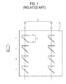
- the single-pass color image forming apparatus forms an ACR pattern 11 in each of the colors Y, M, C and K on a transfer belt 10 by using a developer, and detects the ACR pattern 11 through an ACR detector 15 to thereby perform the ACR.
- the ACR pattern 11 in each color includes a first ACR pattern 11a and a second ACR pattern 11b inclined to the first ACR pattern 11a to identify any error in the ACR in a width direction of the transfer belt 10.
- an image forming apparatus which forms a color image on a print medium by overlapping an image formed in each color
- the image forming apparatus including: a plurality of developing units which each develops a color image in a predetermined color; a transfer unit which transfers the color image developed by the plurality of developing units to the print medium and includes a transfer belt rotatably installed on a transfer path; a first detector which is provided in a predetermined location of the transfer belt to face the transfer belt and detects any defect from a surface of the transfer belt; a second detector which is provided in a predetermined location of the transfer belt to face the transfer belt and detects a test pattern of an auto color registration (ACR) error transferred to the transfer belt; and a controller which adjusts data on the test pattern of the ACR error formed in a defective location of the transfer belt detected by the first detector by using the defective location information, or causes the data on the test pattern of the ACR error formed in the defective location of the transfer belt detected by the first detector not
- an image forming apparatus which forms a color image on a print medium by overlapping an image formed in each color
- the image forming apparatus including: a plurality of developing units which each develops a color image in a predetermined color; a transfer unit which transfers the color image developed by the plurality of developing units to the print medium and includes a transfer belt rotatably installed on a transfer path; a first detector which is provided in a predetermined location of the transfer belt to face the transfer belt and detects any defect from a surface of the transfer belt; a second detector which is provided in a predetermined location of the transfer belt to face the transfer belt and detects a test pattern of an auto color registration (ACR) error transferred to the transfer belt; and a controller which controls the developing units to form the test pattern of the ACR error by avoiding a defective location if the first detector detects the defect from the predetermined location of the transfer belt.
- ACR auto color registration
- a length from the first detector to the second detector of the transfer belt may be relatively longer than a length from the second detector to the first detector of the transfer belt, based on the rotation direction of the transfer belt.
- an auto color registration (ACR) method of an image forming apparatus which forms a color image on a print medium by overlapping an image formed in each color
- the ACR method including: detecting a defect from a surface of a transfer belt by a first detector; printing a test pattern of an ACR error on the transfer belt; detecting the test pattern of the ACR error formed on the transfer belt, by a second detector; determining whether there is any defect from the surface of the transfer belt; and adjusting data on the test pattern of the ACR error formed on a defective location of the transfer belt detected by the first detector by using the defective location information or controlling not to reflect the data on the test pattern of the ACR error formed in the defective location of the transfer belt detected by the first detector in an adjustment of the ACR error.
- the transfer unit 150 may transfer an image on the print medium P by an indirect transfer method.
- the transfer unit 150 primarily transfers the image developed on the image carrier 120 to the transfer belt 151, and then the transfer belt 151 rotates and transfers the image to the print medium P.
- the image transferred to the print medium P through the transfer unit 150 is fused by the fusing unit 160.
- the ACR unit 170 includes first and second detectors 171 and 175 which are installed around the transfer belts 151 and 251 to detect and adjust a defect from a predetermined location due to damage to a surface of the transfer belts 151 and 251 when the ACR process is performed.
- the second detector 175 is provided in a predetermined location between the developing unit 130 and the cleaning blade 155 to face the transfer belts 151 and 251, and reads information on the ACR pattern transferred to the surface of the transfer belts 151 and 251 in the ACR mode.
- the controller 180 may adjust in advance the ACR error based on the data on the ACR pattern formed on the defective location of the transfer belts 151 and 251 detected by the first detector 171, and then reflect the result to a final adjustment of the ACR error. That is, if the defect data on the defect of the surface of the transfer belts 151 and 251 is transmitted by the first detector 171 before the performance of the ACR adjustment algorithm by using the data on the ACR pattern detected by the second detector 175, the controller 180 performs a primary adjustment algorithm in consideration of the defect data and then reflects the ACR pattern data to complete the ACR adjustment.
- the first detector 171 detects any defect from the surface of the transfer belts 151 and 251 on which the ACR pattern is not formed (S120).
- the ACR pattern is formed in the predetermined location of the transfer belts 151 and 251 (S150). If it is determined that there is a defect from the surface of the transfer belts 151 and 251 at operation S130, the ACR pattern is printed on the transfer belts 151 and 251 by avoiding the defective location of the surface of the transfer belts 151 and 251.
- the image forming apparatus includes the first detector 171 to detect the defect from the surface of the transfer belts 151 and 251, in addition to the second detector 175 detecting the ACR pattern, to thereby reflect the detection result of the defect from the surface of the transfer belts to the ACR adjustment without idling the transfer belts unlike in a conventional image forming apparatus.
- the image forming apparatus fundamentally prevents issues such as turn-over of the cleaning blade due to the transfer belt being at idle, and prevent any increase in the ACR time due to the idle.
Landscapes
- Physics & Mathematics (AREA)
- General Physics & Mathematics (AREA)
- Engineering & Computer Science (AREA)
- Microelectronics & Electronic Packaging (AREA)
- Color Electrophotography (AREA)
- Electrostatic Charge, Transfer And Separation In Electrography (AREA)
- Control Or Security For Electrophotography (AREA)
Abstract
Description
- The present invention relates to an image forming apparatus and an auto color registration method of the same, and more particularly, to an image forming apparatus and an auto color registration method of the same which prints a color image by a single pass.
- In general, an electrophotographic image forming apparatus forms an electrostatic latent image on an image carrier charged by a predetermined electric potential, by exposing light thereto, develops the image with a developer in a predetermined color and transfers to a print medium and fuses the image. The electrophotographic image forming apparatus may be classified into a mono type and a color type according to a color realization. The color image forming apparatus may be classified further into a single pass type and a multi pass type according to a transfer method for images in each color.
- The single-pass color image forming apparatus includes a plurality of developers corresponding to each color, e.g., developers corresponding to each of yellow (Y), magenta (M), cyan (C) and black (K) colors; and light scanning units corresponding to the developers to thereby overlap an image formed on the developers by single pass for realization of a color image. The realization of the color image requires an auto color registration (hereinafter, to be called the "ACR") which registers an image in each color developed by the developers, in a correct location.
- As shown in
FIG. 1 , the single-pass color image forming apparatus forms an ACR pattern 11 in each of the colors Y, M, C and K on atransfer belt 10 by using a developer, and detects the ACR pattern 11 through anACR detector 15 to thereby perform the ACR. The ACR pattern 11 in each color includes a first ACR pattern 11a and asecond ACR pattern 11b inclined to the first ACR pattern 11a to identify any error in the ACR in a width direction of thetransfer belt 10. - The ACR pattern 11 is provided in at least two locations in the width direction of the
transfer belt 10. In such a case, theACR detector 15 includes a plurality ofdetectors transfer belt 10. - If an ACR pattern is printed on the
transfer belt 10 for the performance of the ACR, such ACR pattern may be distorted by a defect of a surface of thetransfer belt 10. Then, theACR detector 15 may detect the distorted ACR pattern, leading to a distortion of the ACR. - To prevent the foregoing problem, in the conventional image forming apparatus, the
ACR detector 15 detects any error from the surface of thetransfer belt 10 at idle when the ACR pattern is not printed thereon and reflects such detection result to printing the ACR pattern. - However, in the conventional image forming apparatus, when the transfer belt without the image printed thereto idles, a friction force between the transfer belt and a cleaning blade (not shown) cleaning a remaining developer from the transfer belt becomes higher and may turn over the cleaning blade. If a predetermined pattern is printed on the transfer belt at idle to prevent the turn-over of the cleaning blade, the surface of the transfer belt having the printed pattern thereon is not detected normally and the defect from the surface is not detected nor adjusted.
- In the foregoing method, the transfer belt idles to detect the defect thereof and thus the ACR time increases as much as the idle time.
- In another conventional method, an additional adjustment algorithm is used to adjust such defect based on ACR data without the process of detecting the defect from the surface of the
transfer belt 10. In this case, accuracy of the adjustment deteriorates as the detection of the surface of thetransfer belt 10 is not performed. - Accordingly, one or more exemplary embodiments provide an image forming apparatus and an auto color registration method of the same which improves accuracy of adjustment by detecting a defect from a surface of a transfer belt through a physical detection process and detects such defect without idling the transfer belt.
- The foregoing and/or other aspects may be achieved by providing an image forming apparatus which forms a color image on a print medium by overlapping an image formed in each color, the image forming apparatus including: a plurality of developing units which each develops a color image in a predetermined color; a transfer unit which transfers the color image developed by the plurality of developing units to the print medium and includes a transfer belt rotatably installed on a transfer path; a first detector which is provided in a predetermined location of the transfer belt to face the transfer belt and detects any defect from a surface of the transfer belt; a second detector which is provided in a predetermined location of the transfer belt to face the transfer belt and detects a test pattern of an auto color registration (ACR) error transferred to the transfer belt; and a controller which adjusts data on the test pattern of the ACR error formed in a defective location of the transfer belt detected by the first detector by using the defective location information, or causes the data on the test pattern of the ACR error formed in the defective location of the transfer belt detected by the first detector not to be reflected in an adjustment of the ACR error.
- The transfer unit may further include a cleaning blade which is installed to face the transfer belt and cleans a developer remaining in the surface of the transfer belt.
- The first detector may be arranged in a predetermined location between the cleaning blade and the plurality of developing units to face the transfer belt, and the second detector may be arranged in a predetermined location between the plurality of developing units and the cleaning blade to face the transfer belt, based on a rotation direction of the transfer belt.
- A length from the first detector to the second detector of the transfer belt may be relatively longer than a length from the second detector to the first detector of the transfer belt, based on the rotation direction of the transfer belt.
- The foregoing and/or other aspects may be achieved by providing an image forming apparatus which forms a color image on a print medium by overlapping an image formed in each color, the image forming apparatus including: a plurality of developing units which each develops a color image in a predetermined color; a transfer unit which transfers the color image developed by the plurality of developing units to the print medium and includes a transfer belt rotatably installed on a transfer path; a first detector which is provided in a predetermined location of the transfer belt to face the transfer belt and detects any defect from a surface of the transfer belt; a second detector which is provided in a predetermined location of the transfer belt to face the transfer belt and detects a test pattern of an auto color registration (ACR) error transferred to the transfer belt; and a controller which controls the developing units to form the test pattern of the ACR error by avoiding a defective location if the first detector detects the defect from the predetermined location of the transfer belt.
- The transfer unit may further include a cleaning blade which is installed to face the transfer belt and cleans a developer remaining in the surface of the transfer belt.
- The first detector may be arranged in a predetermined location between the cleaning blade and the plurality of developing units to face the transfer belt, and the second detector may be arranged in a predetermined location between the plurality of developing units and the cleaning blade to face the transfer belt, based on a rotation direction of the transfer belt.
- A length from the first detector to the second detector of the transfer belt may be relatively longer than a length from the second detector to the first detector of the transfer belt, based on the rotation direction of the transfer belt.
- The foregoing and/or other aspects may be achieved by providing an auto color registration (ACR) method of an image forming apparatus which forms a color image on a print medium by overlapping an image formed in each color, the ACR method including: detecting a defect from a surface of a transfer belt by a first detector; printing a test pattern of an ACR error on the transfer belt; detecting the test pattern of the ACR error formed on the transfer belt, by a second detector; determining whether there is any defect from the surface of the transfer belt; and adjusting data on the test pattern of the ACR error formed on a defective location of the transfer belt detected by the first detector by using the defective location information or controlling not to reflect the data on the test pattern of the ACR error formed in the defective location of the transfer belt detected by the first detector in an adjustment of the ACR error.
- In the ACR method, the image forming apparatus may further include a cleaning blade to clean a developer remaining on the surface of the transfer belt, and the first detector may be arranged in a predetermined location between the cleaning blade and a plurality of developing units to face the transfer belt, and the second detector may be arranged in a predetermined location between the plurality of developing units and the cleaning blade to face the transfer belt, based on a rotation direction of the transfer belt.
- In the ACR method, a length from the first detector to the second detector of the transfer belt may be relatively longer than a length from the second detector to the first detector of the transfer belt, based on the rotation direction of the transfer belt.
- The foregoing and/or other aspects may be achieved by providing an auto color registration (ACR) method of an image forming apparatus which forms a color image on a print medium by overlapping an image formed in each color, the ACR method including: detecting a defect from a surface of a transfer belt, by a first detector; determining whether there is any defect from the surface of the transfer belt; printing a test pattern of an ACR error in a predetermined location of the transfer belt if there is no defect on the surface of the transfer belt and printing a test pattern of the ACR error on the transfer belt by avoiding a defective location of the surface if there is the defect on the transfer belt; detecting the test pattern of the ACR error formed on the transfer belt, by a second detector; and adjusting the ACR error result based on the detection result of the second detector.
- In the ACR method, the image forming apparatus may further include a cleaning blade to clean a developer remaining on the surface of the transfer belt, and the first detector may be arranged in a predetermined location between the cleaning blade and a plurality of developing units to face the transfer belt, and the second detector may be arranged in a predetermined location between the plurality of developing units and the cleaning blade to face the transfer belt, based on a rotation direction of the transfer belt.
- In the ACR method, a length from the first detector to the second detector of the transfer belt may be relatively longer than a length from the second detector to the first detector of the transfer belt, based on the rotation direction of the transfer belt.
- The above and/or other aspects will become apparent and more readily appreciated from the following description of the exemplary embodiments, taken in conjunction with the accompanying drawings, in which:
-
FIG. 1 illustrates a test pattern of an auto color registration (ACR) error formed on a surface of a transfer belt and an ACR detector of an image forming apparatus; -
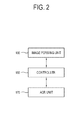
FIG. 2 is a block diagram of an image forming apparatus according to an exemplary embodiment; -
FIG. 3 illustrates an image forming apparatus according to a first exemplary embodiment; -
FIG. 4 illustrates an image forming apparatus according to a second exemplary embodiment; -
FIG. 5 illustrates major parts of the image forming apparatus inFIG. 4 ; -
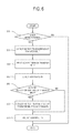
FIG. 6 is a flowchart of an auto color registration method of the image forming apparatus according to the first exemplary embodiment; and -
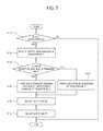
FIG. 7 is a flowchart of an auto color registration method of the image forming apparatus according to the second exemplary embodiment. - Below, exemplary embodiments will be described in detail with reference to accompanying drawings so as to be easily realized by a person having ordinary knowledge in the art. The exemplary embodiments may be embodied in various forms without being limited to the exemplary embodiments set forth herein.
- Descriptions of well-known parts are omitted for clarity, and like reference numerals refer to like elements throughout.
-
FIG. 2 is a block diagram of an image forming apparatus according to an exemplary embodiment.FIG. 3 illustrates an image forming apparatus according to a first exemplary embodiment. - As shown therein, the image forming apparatus according to the exemplary embodiment includes an
image forming unit 100 which independently forms and overlaps an image in each color to form a color image, an automatic color registration unit (hereinafter, to be called ACR unit) 170 which performs an ACR per color to form a color image and acontroller 180 which controls theimage forming unit 100 and theACR unit 170. - The
image forming unit 100 forms a color image on a print medium P fed by amedium feeder 110, and forms a test pattern of ACR errors per color (hereinafter, to be called "ACR pattern") on an image transfer path (e.g., atransfer belt 151 shown inFIG. 3 ) in proportion to the standard of the print medium. - The
image forming unit 100 includes animage carrier 120, anexposing unit 140 which scans light to theimage carrier 120 to form a latent image thereon, a developingunit 130 which develops a developer to the latent image formed on theimage carrier 120 to form an image, atransfer unit 150 which transfers a developer image from theimage carrier 120 to a print medium P, and afusing unit 160 which fuses the image transferred to the print medium P by heat and pressure. - The developing
unit 130 is arranged to face theimage carrier 120 and develops a developer to an area where a latent image on theimage carrier 120 is formed. The developingunit 130 and theimage carrier 120 are provided for each color to thereby form a full color image by a single pass.FIG. 3 illustrates four units to realize yellow (Y), magenta (M), cyan (C) and black (K) colors, respectively. - The exposing
unit 140 scans light beam to form an electrostatic latent image on each of a plurality ofimage carriers 120. - The
transfer unit 150 transfers to the print medium P a color image developed by the plurality of developingunits 130. Thetransfer unit 150 includes atransfer belt 151 which faces theimage carrier 120 and is rotatably installed on a transfer path, and a supportingroller 152 which rotatably supports thetransfer belt 151. - The
transfer unit 150 may transfer an image on the print medium P by an indirect transfer method. In this case, thetransfer unit 150 primarily transfers the image developed on theimage carrier 120 to thetransfer belt 151, and then thetransfer belt 151 rotates and transfers the image to the print medium P. The image transferred to the print medium P through thetransfer unit 150 is fused by thefusing unit 160. - The
transfer unit 150 of the image forming apparatus according to the exemplary embodiment may further include acleaning blade 155. Thecleaning blade 155 is installed to face thetransfer belt 151, and cleans a developer remaining in a surface of thetransfer belt 151 after the transfer of the image. - The single-pass color image forming apparatus may include a charger (not shown) which charges the
image carrier 120 with a predetermined electric potential, a discharger (not shown) which removes an electric charge remaining in theimage carrier 120, and a cleaning unit (not shown) which cleans dirt from theimage carrier 120, which are provided in locations corresponding to the plurality ofimage carriers 120. -
FIG. 4 illustrates an image forming apparatus according to a second exemplary embodiment. Compared to the image forming apparatus according to the first exemplary embodiment, the image forming apparatus according to the second exemplary embodiment is substantially the same as that according to the first exemplary embodiment except it transfers an image by a direct transfer method. - Thus, elements other than the
transfer unit 250 are given the same names and numerals as those according to the first exemplary embodiment and the detailed description will be omitted. - Referring to
FIG. 4 , thetransfer unit 250 transfers an image to the print medium P by a direct transfer method. Thus, thetransfer unit 250 is provided to face theimage carrier 120 leaving the print medium P moved along a moving path therebetween, and directly transfers a color image developed by the plurality of developingunits 130 to the print medium P. Thetransfer unit 250 includes atransfer belt 251 rotatably installed on a transfer path, and a supportingroller 252 rotatably supporting thetransfer belt 251. - As shown in
FIGS. 3 and4 , theACR unit 170 includes first andsecond detectors transfer belts transfer belts - The
first detector 171 is provided in a predetermined location of thetransfer belts transfer belts first detector 171 is arranged in a predetermined location between thecleaning blade 155 and the plurality of developingunits 130 to face thetransfer belts transfer belts first detector 171 may detect a defect from the surface of thetransfer belts cleaning blade 155 with respect to a developer remaining on the surface of thetransfer belts - The
second detector 175 is provided in a predetermined location of thetransfer belts first detector 171, and detects an ACR pattern transferred to thetransfer belts transfer belts image forming unit 100 in an ACR mode, and may be formed on the surface of thetransfer belts FIG. 1 . - The
second detector 175 is provided in a predetermined location between the developingunit 130 and thecleaning blade 155 to face thetransfer belts transfer belts - Based on the rotation direction of the
transfer belts first detector 171 to thesecond detector 175 of thetransfer belts second detector 175 to thefirst detector 171 as shown inFIG. 5 . Thus, the detection time of thefirst detector 171 may be longer than the detection time of thesecond detector 175, and the detection result of the defect from the surface of thetransfer belts - The
controller 180 adjusts an ACR error based on data on the defect of the surface of thetransfer belts first detector 171, and data on the ACR pattern detected by thesecond detector 175. That is, thecontroller 180 may cause the data on the ACR pattern formed on the defective location not to be reflected in the adjustment of the ACR error, based on the defective location information of thetransfer belts first detector 171. - Accordingly, the data on the defect of the surface of the
transfer belts - The
controller 180 may adjust in advance the ACR error based on the data on the ACR pattern formed on the defective location of thetransfer belts first detector 171, and then reflect the result to a final adjustment of the ACR error. That is, if the defect data on the defect of the surface of thetransfer belts first detector 171 before the performance of the ACR adjustment algorithm by using the data on the ACR pattern detected by thesecond detector 175, thecontroller 180 performs a primary adjustment algorithm in consideration of the defect data and then reflects the ACR pattern data to complete the ACR adjustment. - If the defect from the predetermined location of the
transfer belts first detector 171, thecontroller 180 may control the developingunit 130 to form an ACR pattern by avoiding the defective location. - An auto color registration (ACR) method of the image forming apparatus according to the first and second exemplary embodiments will be described in detail with reference to drawings.
-
FIG. 6 is a flowchart of an ACR method of the image forming apparatus according to the first exemplary embodiment. - Referring to
FIGS. 2 to 6 , in the ACR method of the image forming apparatus, it is determined whether the image forming apparatus enters an ACR mode (S10). That is, the ACR mode is entered when the ACR performance conditions set for the image forming apparatus are met or when it is determined that there is a problem in an ACR by a user. - When the ACR mode is entered, the
first detector 171 detects any defect from the surface of thetransfer belts transfer belts units 130 and the image carriers 120 (S30), and thesecond detector 175 detects the ACR pattern formed on thetransfer belts 151 and 251 (S40). - Then, whether there is any defect from the surface of the
transfer belts - At operation S60, the defective location information of the
transfer belts first detector 171 may be used not to reflect the data on the ACR pattern formed in the defective location, in the adjustment of the ACR error, or adjust the data on the ACR pattern formed in the defective location to reflect the adjustment to the final adjustment of the ACR error. -
FIG. 7 is a flowchart of an ACR method of the image forming apparatus according to the second exemplary embodiment. - Referring to
FIGS. 2 to 5 and7 , in the ACR method of the image forming apparatus, it is determined whether the image forming apparatus enters the ACR mode (S110). In the ACR mode, thefirst detector 171 detects any defect from the surface of thetransfer belts - Then, whether there is any defect from the surface of the
transfer belts transfer belts transfer belts 151 and 251 (S150). If it is determined that there is a defect from the surface of thetransfer belts transfer belts transfer belts - Then, the
second detector 175 detects the ACR pattern formed on thetransfer belts 151 and 251 (S160), and the ACR result is adjusted on the basis of the detected data (S170). - The image forming apparatus according to the exemplary embodiments includes the
first detector 171 to detect the defect from the surface of thetransfer belts second detector 175 detecting the ACR pattern, to thereby reflect the detection result of the defect from the surface of the transfer belts to the ACR adjustment without idling the transfer belts unlike in a conventional image forming apparatus. Thus, the image forming apparatus according to the exemplary embodiments fundamentally prevents issues such as turn-over of the cleaning blade due to the transfer belt being at idle, and prevent any increase in the ACR time due to the idle. - As described above, an image forming apparatus and an auto color registration method of the same according to the exemplary embodiments includes a first detector to detecting a defect from a surface of a transfer belt, in addition to a second detector detecting an ACR pattern, to thereby reflect a detection result of the defect from the surface of the transfer belt to the ACR adjustment without idling the transfer belt, fundamentally prevent problems such as turn-over of a cleaning blade due to the idling transfer belt, and prevent increase in ACR time due to the idle.
- Although a few exemplary embodiments have been shown and described, it will be appreciated by those skilled in the art that changes may be made in these exemplary embodiments without departing from the principles of the invention, the range of which is defined in the appended claims.
Claims (8)
- An image forming apparatus which forms a color image on a print medium by overlapping an image formed in each color, the image forming apparatus comprising:a plurality of developing units each configured to develop a color image in a predetermined color;a transfer unit configured to transfer the color image developed by the plurality of developing units to the print medium, the transfer unit comprising a transfer belt rotatably installed on a transfer path;a first detector which is provided in a predetermined location of the transfer belt to face the transfer belt and detect any defect from a surface of the transfer belt;a second detector which is provided in a predetermined location of the transfer belt to face the transfer belt and detect a test pattern of an auto color registration (ACR) error transferred to the transfer belt; anda controller which adjusts data on the test pattern of the ACR error formed in a defective location of the transfer belt detected by the first detector by using the defective location information, causes the data on the test pattern of the ACR error formed in the defective location of the transfer belt detected by the first detector not to be reflected in an adjustment of the ACR error, or controls the developing units to form the test pattern of the ACR error by avoiding a defective location if the first detector detects the defect from the predetermined location of the transfer belt.
- The image forming apparatus according to claim 1, wherein the transfer unit further comprises a cleaning blade which is installed to face the transfer belt and cleans a developer remaining in the surface of the transfer belt.
- The image forming apparatus according to claim 2, wherein the first detector is arranged in a predetermined location between the cleaning blade and the plurality of developing units to face the transfer belt, and the second detector is arranged in a predetermined location between the plurality of developing units and the cleaning blade to face the transfer belt, based on a rotation direction of the transfer belt.
- The image forming apparatus as claimed in any one of claims 1 to 3, wherein a length from the first detector to the second detector of the transfer belt is longer than a length from the second detector to the first detector of the transfer belt, based on the rotation direction of the transfer belt.
- An auto color registration (ACR) method of an image forming apparatus which forms a color image on a print medium by overlapping an image formed in each color, the ACR method comprising:detecting a defect from a surface of a transfer belt by a first detector;determining whether there is any defect from the surface of the transfer belt;printing a test pattern of an ACR error on a predetermined location of the transfer belt;detecting the test pattern of the ACR error formed on the transfer belt by a second detector; andadjusting data on the test pattern of the ACR error formed on a defective location of the transfer belt detected by the first detector by using the defective location information, controlling not to reflect the data on the test pattern of the ACR error formed in the defective location of the transfer belt detected by the first detector in an adjustment of the ACR error, or controlling to print a test pattern of the ACR error on the transfer belt by avoiding a defective location of the surface if there is the defect on the transfer belt and to adjust the ACR error result based on the detection result of the second detector.
- The ACR method according to claim 5, wherein the image forming apparatus further comprises a cleaning blade to clean a developer remaining on the surface of the transfer belt.
- The ACR method according to claim 6, wherein the first detector is arranged in a predetermined location between the cleaning blade and a plurality of developing units to face the transfer belt, and the second detector is arranged in a predetermined location between the plurality of developing units and the cleaning blade to face the transfer belt, based on a rotation direction of the transfer belt.
- The ACR method as claimed in any one of claims 5 to 7, wherein a length from the first detector to the second detector of the transfer belt is longer than a length from the second detector to the first detector of the transfer belt, based on the rotation direction of the transfer belt.
Applications Claiming Priority (1)
| Application Number | Priority Date | Filing Date | Title |
|---|---|---|---|
| KR20100130919 | 2010-12-20 |
Publications (3)
| Publication Number | Publication Date |
|---|---|
| EP2466385A1 true EP2466385A1 (en) | 2012-06-20 |
| EP2466385B1 EP2466385B1 (en) | 2019-10-30 |
| EP2466385B8 EP2466385B8 (en) | 2019-12-11 |
Family
ID=44651348
Family Applications (1)
| Application Number | Title | Priority Date | Filing Date |
|---|---|---|---|
| EP11181542.9A Active EP2466385B8 (en) | 2010-12-20 | 2011-09-16 | Image forming apparatus and auto color registration method of the same |
Country Status (3)
| Country | Link |
|---|---|
| US (1) | US8948667B2 (en) |
| EP (1) | EP2466385B8 (en) |
| KR (1) | KR101838671B1 (en) |
Cited By (1)
| Publication number | Priority date | Publication date | Assignee | Title |
|---|---|---|---|---|
| EP2549334A1 (en) * | 2011-07-20 | 2013-01-23 | Ricoh Company, Ltd. | Image forming apparatus and method thereof |
Families Citing this family (12)
| Publication number | Priority date | Publication date | Assignee | Title |
|---|---|---|---|---|
| US8319202B2 (en) * | 2010-04-06 | 2012-11-27 | Xerox Corporation | Color registration strategy for preprinted forms |
| US20110242187A1 (en) | 2010-04-06 | 2011-10-06 | Xerox Corporation | Test Pattern Effective For Fine Registration Of Inkjet Printheads And Method Of Analysis Of Image Data Corresponding To The Test Pattern In An Inkjet Printer |
| US8602518B2 (en) | 2010-04-06 | 2013-12-10 | Xerox Corporation | Test pattern effective for coarse registration of inkjet printheads and methods of analysis of image data corresponding to the test pattern in an inkjet printer |
| US8376516B2 (en) | 2010-04-06 | 2013-02-19 | Xerox Corporation | System and method for operating a web printing system to compensate for dimensional changes in the web |
| US8585173B2 (en) | 2011-02-14 | 2013-11-19 | Xerox Corporation | Test pattern less perceptible to human observation and method of analysis of image data corresponding to the test pattern in an inkjet printer |
| JP5919917B2 (en) * | 2012-03-16 | 2016-05-18 | 富士ゼロックス株式会社 | Density detector and image forming apparatus |
| JP6384136B2 (en) * | 2014-06-12 | 2018-09-05 | 株式会社リコー | Image forming apparatus |
| JP6488748B2 (en) * | 2015-02-13 | 2019-03-27 | コニカミノルタ株式会社 | Image forming apparatus |
| JP6543997B2 (en) * | 2015-03-30 | 2019-07-17 | ブラザー工業株式会社 | Image forming apparatus, control method, computer program |
| JP6661300B2 (en) * | 2015-08-17 | 2020-03-11 | キヤノン株式会社 | Image forming device |
| JP6769205B2 (en) * | 2016-09-21 | 2020-10-14 | 富士ゼロックス株式会社 | Image forming device |
| JP7472456B2 (en) * | 2019-10-01 | 2024-04-23 | 富士フイルムビジネスイノベーション株式会社 | Image forming device |
Citations (2)
| Publication number | Priority date | Publication date | Assignee | Title |
|---|---|---|---|---|
| US5784676A (en) * | 1995-04-14 | 1998-07-21 | Fuji Xerox Co., Ltd. | Roller for belt transporting apparatus and image forming apparatus |
| US20100178084A1 (en) * | 2009-01-12 | 2010-07-15 | Samsung Electronics Co., Ltd | Image forming apparatus and auto color registration method thereof |
Family Cites Families (11)
| Publication number | Priority date | Publication date | Assignee | Title |
|---|---|---|---|---|
| US5291245A (en) * | 1993-03-23 | 1994-03-01 | Xerox Corporation | Photoreceptor belt seam detection and process control |
| US6493533B1 (en) * | 1998-10-30 | 2002-12-10 | Canon Kabushiki Kaisha | Image forming apparatus having a belt member and a driving roller for the belt member |
| JP2000137367A (en) | 1998-11-02 | 2000-05-16 | Matsushita Electric Ind Co Ltd | Color image forming apparatus and registration pattern forming method |
| JP4298157B2 (en) | 2000-12-07 | 2009-07-15 | キヤノン株式会社 | Image forming apparatus |
| JP2003122082A (en) * | 2001-10-09 | 2003-04-25 | Canon Inc | Image forming device |
| JP3797218B2 (en) * | 2001-12-28 | 2006-07-12 | コニカミノルタホールディングス株式会社 | Color image forming apparatus |
| JP2004317799A (en) * | 2003-04-16 | 2004-11-11 | Canon Inc | Image information detection sensor |
| KR100619079B1 (en) * | 2005-05-16 | 2006-08-31 | 삼성전자주식회사 | Method and apparatus for adjusting color alignment of image forming apparatus using pattern |
| KR100695071B1 (en) * | 2005-06-29 | 2007-03-14 | 삼성전자주식회사 | Color registration correction method and correction device |
| JP4819492B2 (en) * | 2005-12-08 | 2011-11-24 | 株式会社リコー | Transfer device, image forming device |
| JP4989169B2 (en) * | 2006-09-19 | 2012-08-01 | キヤノン株式会社 | Image forming apparatus and control method |
-
2011
- 2011-08-19 KR KR1020110082508A patent/KR101838671B1/en not_active Expired - Fee Related
- 2011-09-14 US US13/137,817 patent/US8948667B2/en active Active
- 2011-09-16 EP EP11181542.9A patent/EP2466385B8/en active Active
Patent Citations (2)
| Publication number | Priority date | Publication date | Assignee | Title |
|---|---|---|---|---|
| US5784676A (en) * | 1995-04-14 | 1998-07-21 | Fuji Xerox Co., Ltd. | Roller for belt transporting apparatus and image forming apparatus |
| US20100178084A1 (en) * | 2009-01-12 | 2010-07-15 | Samsung Electronics Co., Ltd | Image forming apparatus and auto color registration method thereof |
Cited By (2)
| Publication number | Priority date | Publication date | Assignee | Title |
|---|---|---|---|---|
| EP2549334A1 (en) * | 2011-07-20 | 2013-01-23 | Ricoh Company, Ltd. | Image forming apparatus and method thereof |
| US9442447B2 (en) | 2011-07-20 | 2016-09-13 | Ricoh Company, Ltd. | Image forming apparatus, method thereof, and computer program product |
Also Published As
| Publication number | Publication date |
|---|---|
| EP2466385B8 (en) | 2019-12-11 |
| KR101838671B1 (en) | 2018-03-15 |
| US8948667B2 (en) | 2015-02-03 |
| EP2466385B1 (en) | 2019-10-30 |
| US20120155894A1 (en) | 2012-06-21 |
| KR20120069523A (en) | 2012-06-28 |
Similar Documents
| Publication | Publication Date | Title |
|---|---|---|
| EP2466385B1 (en) | Image forming apparatus and auto color registration method of the same | |
| US7764897B2 (en) | Color image forming apparatus and control method therefor | |
| JP5256873B2 (en) | Image forming apparatus and image forming method | |
| US7817947B2 (en) | Image forming apparatus and correction method of color-misregistration in an image | |
| US7389075B2 (en) | Image forming apparatus, program and positional error correction method | |
| US8249474B2 (en) | Image forming apparatus which controls image forming conditions based on residual toner of a detection pattern | |
| JP4498216B2 (en) | Color image forming apparatus and control method thereof | |
| JP5258850B2 (en) | Image forming apparatus | |
| JP4329775B2 (en) | Image forming apparatus and method for detecting separation state of transfer member | |
| JP4592247B2 (en) | Image forming apparatus | |
| JP5153250B2 (en) | Image forming apparatus | |
| US11815839B2 (en) | Image forming apparatus capable of adjusting image forming condition accurately, and image forming condition adjustment method | |
| US9164455B2 (en) | Image forming apparatus | |
| US8862011B2 (en) | Image forming apparatus having test image formation | |
| JP5049053B2 (en) | Image forming apparatus | |
| JP2007155895A (en) | Color image forming apparatus | |
| JP7508771B2 (en) | Image forming apparatus and method for identifying position of defective image | |
| JP3542148B2 (en) | Image forming device | |
| JP2004341233A (en) | Image forming apparatus and image density control method | |
| US7580650B2 (en) | Image forming device and image forming method including formation of a toner patch | |
| JP2006276662A (en) | Image forming apparatus | |
| JP2008175966A (en) | Tandem type color image forming apparatus | |
| JP4967374B2 (en) | Image forming apparatus | |
| JP2003098794A (en) | Image forming apparatus | |
| US20090297187A1 (en) | Multi-sensor calibration technique |
Legal Events
| Date | Code | Title | Description |
|---|---|---|---|
| PUAI | Public reference made under article 153(3) epc to a published international application that has entered the european phase |
Free format text: ORIGINAL CODE: 0009012 |
|
| AK | Designated contracting states |
Kind code of ref document: A1 Designated state(s): AL AT BE BG CH CY CZ DE DK EE ES FI FR GB GR HR HU IE IS IT LI LT LU LV MC MK MT NL NO PL PT RO RS SE SI SK SM TR |
|
| AX | Request for extension of the european patent |
Extension state: BA ME |
|
| RAP1 | Party data changed (applicant data changed or rights of an application transferred) |
Owner name: SAMSUNG ELECTRONICS CO., LTD. |
|
| 17P | Request for examination filed |
Effective date: 20121218 |
|
| 17Q | First examination report despatched |
Effective date: 20130422 |
|
| RAP1 | Party data changed (applicant data changed or rights of an application transferred) |
Owner name: S-PRINTING SOLUTION CO., LTD. |
|
| RAP1 | Party data changed (applicant data changed or rights of an application transferred) |
Owner name: HP PRINTING KOREA CO., LTD. |
|
| GRAP | Despatch of communication of intention to grant a patent |
Free format text: ORIGINAL CODE: EPIDOSNIGR1 |
|
| STAA | Information on the status of an ep patent application or granted ep patent |
Free format text: STATUS: GRANT OF PATENT IS INTENDED |
|
| INTG | Intention to grant announced |
Effective date: 20190624 |
|
| GRAS | Grant fee paid |
Free format text: ORIGINAL CODE: EPIDOSNIGR3 |
|
| GRAA | (expected) grant |
Free format text: ORIGINAL CODE: 0009210 |
|
| STAA | Information on the status of an ep patent application or granted ep patent |
Free format text: STATUS: THE PATENT HAS BEEN GRANTED |
|
| AK | Designated contracting states |
Kind code of ref document: B1 Designated state(s): AL AT BE BG CH CY CZ DE DK EE ES FI FR GB GR HR HU IE IS IT LI LT LU LV MC MK MT NL NO PL PT RO RS SE SI SK SM TR |
|
| REG | Reference to a national code |
Ref country code: GB Ref legal event code: FG4D |
|
| REG | Reference to a national code |
Ref country code: CH Ref legal event code: EP |
|
| REG | Reference to a national code |
Ref country code: CH Ref legal event code: PK Free format text: BERICHTIGUNG B8 Ref country code: AT Ref legal event code: REF Ref document number: 1196796 Country of ref document: AT Kind code of ref document: T Effective date: 20191115 |
|
| REG | Reference to a national code |
Ref country code: DE Ref legal event code: R096 Ref document number: 602011063022 Country of ref document: DE |
|
| REG | Reference to a national code |
Ref country code: IE Ref legal event code: FG4D |
|
| RAP2 | Party data changed (patent owner data changed or rights of a patent transferred) |
Owner name: HEWLETT-PACKARD DEVELOPMENT COMPANY, L.P. |
|
| REG | Reference to a national code |
Ref country code: LT Ref legal event code: MG4D |
|
| PG25 | Lapsed in a contracting state [announced via postgrant information from national office to epo] |
Ref country code: NL Free format text: LAPSE BECAUSE OF FAILURE TO SUBMIT A TRANSLATION OF THE DESCRIPTION OR TO PAY THE FEE WITHIN THE PRESCRIBED TIME-LIMIT Effective date: 20191030 Ref country code: LV Free format text: LAPSE BECAUSE OF FAILURE TO SUBMIT A TRANSLATION OF THE DESCRIPTION OR TO PAY THE FEE WITHIN THE PRESCRIBED TIME-LIMIT Effective date: 20191030 Ref country code: SE Free format text: LAPSE BECAUSE OF FAILURE TO SUBMIT A TRANSLATION OF THE DESCRIPTION OR TO PAY THE FEE WITHIN THE PRESCRIBED TIME-LIMIT Effective date: 20191030 Ref country code: BG Free format text: LAPSE BECAUSE OF FAILURE TO SUBMIT A TRANSLATION OF THE DESCRIPTION OR TO PAY THE FEE WITHIN THE PRESCRIBED TIME-LIMIT Effective date: 20200130 Ref country code: FI Free format text: LAPSE BECAUSE OF FAILURE TO SUBMIT A TRANSLATION OF THE DESCRIPTION OR TO PAY THE FEE WITHIN THE PRESCRIBED TIME-LIMIT Effective date: 20191030 Ref country code: PT Free format text: LAPSE BECAUSE OF FAILURE TO SUBMIT A TRANSLATION OF THE DESCRIPTION OR TO PAY THE FEE WITHIN THE PRESCRIBED TIME-LIMIT Effective date: 20200302 Ref country code: NO Free format text: LAPSE BECAUSE OF FAILURE TO SUBMIT A TRANSLATION OF THE DESCRIPTION OR TO PAY THE FEE WITHIN THE PRESCRIBED TIME-LIMIT Effective date: 20200130 Ref country code: LT Free format text: LAPSE BECAUSE OF FAILURE TO SUBMIT A TRANSLATION OF THE DESCRIPTION OR TO PAY THE FEE WITHIN THE PRESCRIBED TIME-LIMIT Effective date: 20191030 Ref country code: ES Free format text: LAPSE BECAUSE OF FAILURE TO SUBMIT A TRANSLATION OF THE DESCRIPTION OR TO PAY THE FEE WITHIN THE PRESCRIBED TIME-LIMIT Effective date: 20191030 Ref country code: PL Free format text: LAPSE BECAUSE OF FAILURE TO SUBMIT A TRANSLATION OF THE DESCRIPTION OR TO PAY THE FEE WITHIN THE PRESCRIBED TIME-LIMIT Effective date: 20191030 Ref country code: GR Free format text: LAPSE BECAUSE OF FAILURE TO SUBMIT A TRANSLATION OF THE DESCRIPTION OR TO PAY THE FEE WITHIN THE PRESCRIBED TIME-LIMIT Effective date: 20200131 |
|
| REG | Reference to a national code |
Ref country code: NL Ref legal event code: MP Effective date: 20191030 |
|
| PG25 | Lapsed in a contracting state [announced via postgrant information from national office to epo] |
Ref country code: HR Free format text: LAPSE BECAUSE OF FAILURE TO SUBMIT A TRANSLATION OF THE DESCRIPTION OR TO PAY THE FEE WITHIN THE PRESCRIBED TIME-LIMIT Effective date: 20191030 Ref country code: IS Free format text: LAPSE BECAUSE OF FAILURE TO SUBMIT A TRANSLATION OF THE DESCRIPTION OR TO PAY THE FEE WITHIN THE PRESCRIBED TIME-LIMIT Effective date: 20200229 Ref country code: RS Free format text: LAPSE BECAUSE OF FAILURE TO SUBMIT A TRANSLATION OF THE DESCRIPTION OR TO PAY THE FEE WITHIN THE PRESCRIBED TIME-LIMIT Effective date: 20191030 |
|
| PG25 | Lapsed in a contracting state [announced via postgrant information from national office to epo] |
Ref country code: AL Free format text: LAPSE BECAUSE OF FAILURE TO SUBMIT A TRANSLATION OF THE DESCRIPTION OR TO PAY THE FEE WITHIN THE PRESCRIBED TIME-LIMIT Effective date: 20191030 |
|
| PG25 | Lapsed in a contracting state [announced via postgrant information from national office to epo] |
Ref country code: CZ Free format text: LAPSE BECAUSE OF FAILURE TO SUBMIT A TRANSLATION OF THE DESCRIPTION OR TO PAY THE FEE WITHIN THE PRESCRIBED TIME-LIMIT Effective date: 20191030 Ref country code: RO Free format text: LAPSE BECAUSE OF FAILURE TO SUBMIT A TRANSLATION OF THE DESCRIPTION OR TO PAY THE FEE WITHIN THE PRESCRIBED TIME-LIMIT Effective date: 20191030 Ref country code: DK Free format text: LAPSE BECAUSE OF FAILURE TO SUBMIT A TRANSLATION OF THE DESCRIPTION OR TO PAY THE FEE WITHIN THE PRESCRIBED TIME-LIMIT Effective date: 20191030 Ref country code: EE Free format text: LAPSE BECAUSE OF FAILURE TO SUBMIT A TRANSLATION OF THE DESCRIPTION OR TO PAY THE FEE WITHIN THE PRESCRIBED TIME-LIMIT Effective date: 20191030 |
|
| REG | Reference to a national code |
Ref country code: DE Ref legal event code: R097 Ref document number: 602011063022 Country of ref document: DE |
|
| REG | Reference to a national code |
Ref country code: AT Ref legal event code: MK05 Ref document number: 1196796 Country of ref document: AT Kind code of ref document: T Effective date: 20191030 |
|
| PG25 | Lapsed in a contracting state [announced via postgrant information from national office to epo] |
Ref country code: IT Free format text: LAPSE BECAUSE OF FAILURE TO SUBMIT A TRANSLATION OF THE DESCRIPTION OR TO PAY THE FEE WITHIN THE PRESCRIBED TIME-LIMIT Effective date: 20191030 Ref country code: SK Free format text: LAPSE BECAUSE OF FAILURE TO SUBMIT A TRANSLATION OF THE DESCRIPTION OR TO PAY THE FEE WITHIN THE PRESCRIBED TIME-LIMIT Effective date: 20191030 Ref country code: SM Free format text: LAPSE BECAUSE OF FAILURE TO SUBMIT A TRANSLATION OF THE DESCRIPTION OR TO PAY THE FEE WITHIN THE PRESCRIBED TIME-LIMIT Effective date: 20191030 |
|
| PLBE | No opposition filed within time limit |
Free format text: ORIGINAL CODE: 0009261 |
|
| STAA | Information on the status of an ep patent application or granted ep patent |
Free format text: STATUS: NO OPPOSITION FILED WITHIN TIME LIMIT |
|
| 26N | No opposition filed |
Effective date: 20200731 |
|
| PG25 | Lapsed in a contracting state [announced via postgrant information from national office to epo] |
Ref country code: SI Free format text: LAPSE BECAUSE OF FAILURE TO SUBMIT A TRANSLATION OF THE DESCRIPTION OR TO PAY THE FEE WITHIN THE PRESCRIBED TIME-LIMIT Effective date: 20191030 Ref country code: AT Free format text: LAPSE BECAUSE OF FAILURE TO SUBMIT A TRANSLATION OF THE DESCRIPTION OR TO PAY THE FEE WITHIN THE PRESCRIBED TIME-LIMIT Effective date: 20191030 |
|
| PGFP | Annual fee paid to national office [announced via postgrant information from national office to epo] |
Ref country code: FR Payment date: 20201214 Year of fee payment: 11 |
|
| PG25 | Lapsed in a contracting state [announced via postgrant information from national office to epo] |
Ref country code: MC Free format text: LAPSE BECAUSE OF FAILURE TO SUBMIT A TRANSLATION OF THE DESCRIPTION OR TO PAY THE FEE WITHIN THE PRESCRIBED TIME-LIMIT Effective date: 20191030 |
|
| REG | Reference to a national code |
Ref country code: CH Ref legal event code: PL |
|
| REG | Reference to a national code |
Ref country code: BE Ref legal event code: MM Effective date: 20200930 |
|
| PG25 | Lapsed in a contracting state [announced via postgrant information from national office to epo] |
Ref country code: LU Free format text: LAPSE BECAUSE OF NON-PAYMENT OF DUE FEES Effective date: 20200916 |
|
| PG25 | Lapsed in a contracting state [announced via postgrant information from national office to epo] |
Ref country code: CH Free format text: LAPSE BECAUSE OF NON-PAYMENT OF DUE FEES Effective date: 20200930 Ref country code: BE Free format text: LAPSE BECAUSE OF NON-PAYMENT OF DUE FEES Effective date: 20200930 Ref country code: IE Free format text: LAPSE BECAUSE OF NON-PAYMENT OF DUE FEES Effective date: 20200916 Ref country code: LI Free format text: LAPSE BECAUSE OF NON-PAYMENT OF DUE FEES Effective date: 20200930 |
|
| PGFP | Annual fee paid to national office [announced via postgrant information from national office to epo] |
Ref country code: GB Payment date: 20210820 Year of fee payment: 11 Ref country code: DE Payment date: 20201214 Year of fee payment: 11 |
|
| PG25 | Lapsed in a contracting state [announced via postgrant information from national office to epo] |
Ref country code: TR Free format text: LAPSE BECAUSE OF FAILURE TO SUBMIT A TRANSLATION OF THE DESCRIPTION OR TO PAY THE FEE WITHIN THE PRESCRIBED TIME-LIMIT Effective date: 20191030 Ref country code: MT Free format text: LAPSE BECAUSE OF FAILURE TO SUBMIT A TRANSLATION OF THE DESCRIPTION OR TO PAY THE FEE WITHIN THE PRESCRIBED TIME-LIMIT Effective date: 20191030 Ref country code: CY Free format text: LAPSE BECAUSE OF FAILURE TO SUBMIT A TRANSLATION OF THE DESCRIPTION OR TO PAY THE FEE WITHIN THE PRESCRIBED TIME-LIMIT Effective date: 20191030 |
|
| PG25 | Lapsed in a contracting state [announced via postgrant information from national office to epo] |
Ref country code: MK Free format text: LAPSE BECAUSE OF FAILURE TO SUBMIT A TRANSLATION OF THE DESCRIPTION OR TO PAY THE FEE WITHIN THE PRESCRIBED TIME-LIMIT Effective date: 20191030 |
|
| REG | Reference to a national code |
Ref country code: DE Ref legal event code: R119 Ref document number: 602011063022 Country of ref document: DE |
|
| GBPC | Gb: european patent ceased through non-payment of renewal fee |
Effective date: 20220916 |
|
| PG25 | Lapsed in a contracting state [announced via postgrant information from national office to epo] |
Ref country code: FR Free format text: LAPSE BECAUSE OF NON-PAYMENT OF DUE FEES Effective date: 20220930 Ref country code: DE Free format text: LAPSE BECAUSE OF NON-PAYMENT OF DUE FEES Effective date: 20230401 |
|
| PG25 | Lapsed in a contracting state [announced via postgrant information from national office to epo] |
Ref country code: GB Free format text: LAPSE BECAUSE OF NON-PAYMENT OF DUE FEES Effective date: 20220916 |