EP2466332A2 - Performing receive-focusing based on mid-point algorithm in ultrasound system - Google Patents
Performing receive-focusing based on mid-point algorithm in ultrasound system Download PDFInfo
- Publication number
- EP2466332A2 EP2466332A2 EP11193764A EP11193764A EP2466332A2 EP 2466332 A2 EP2466332 A2 EP 2466332A2 EP 11193764 A EP11193764 A EP 11193764A EP 11193764 A EP11193764 A EP 11193764A EP 2466332 A2 EP2466332 A2 EP 2466332A2
- Authority
- EP
- European Patent Office
- Prior art keywords
- signals
- ultrasound
- living body
- pulse rate
- delay value
- Prior art date
- Legal status (The legal status is an assumption and is not a legal conclusion. Google has not performed a legal analysis and makes no representation as to the accuracy of the status listed.)
- Withdrawn
Links
Images


Classifications
-
- G—PHYSICS
- G01—MEASURING; TESTING
- G01S—RADIO DIRECTION-FINDING; RADIO NAVIGATION; DETERMINING DISTANCE OR VELOCITY BY USE OF RADIO WAVES; LOCATING OR PRESENCE-DETECTING BY USE OF THE REFLECTION OR RERADIATION OF RADIO WAVES; ANALOGOUS ARRANGEMENTS USING OTHER WAVES
- G01S15/00—Systems using the reflection or reradiation of acoustic waves, e.g. sonar systems
- G01S15/88—Sonar systems specially adapted for specific applications
- G01S15/89—Sonar systems specially adapted for specific applications for mapping or imaging
- G01S15/8906—Short-range imaging systems; Acoustic microscope systems using pulse-echo techniques
- G01S15/8979—Combined Doppler and pulse-echo imaging systems
-
- G—PHYSICS
- G01—MEASURING; TESTING
- G01S—RADIO DIRECTION-FINDING; RADIO NAVIGATION; DETERMINING DISTANCE OR VELOCITY BY USE OF RADIO WAVES; LOCATING OR PRESENCE-DETECTING BY USE OF THE REFLECTION OR RERADIATION OF RADIO WAVES; ANALOGOUS ARRANGEMENTS USING OTHER WAVES
- G01S15/00—Systems using the reflection or reradiation of acoustic waves, e.g. sonar systems
- G01S15/88—Sonar systems specially adapted for specific applications
- G01S15/89—Sonar systems specially adapted for specific applications for mapping or imaging
- G01S15/8906—Short-range imaging systems; Acoustic microscope systems using pulse-echo techniques
- G01S15/8909—Short-range imaging systems; Acoustic microscope systems using pulse-echo techniques using a static transducer configuration
- G01S15/8915—Short-range imaging systems; Acoustic microscope systems using pulse-echo techniques using a static transducer configuration using a transducer array
-
- G—PHYSICS
- G01—MEASURING; TESTING
- G01S—RADIO DIRECTION-FINDING; RADIO NAVIGATION; DETERMINING DISTANCE OR VELOCITY BY USE OF RADIO WAVES; LOCATING OR PRESENCE-DETECTING BY USE OF THE REFLECTION OR RERADIATION OF RADIO WAVES; ANALOGOUS ARRANGEMENTS USING OTHER WAVES
- G01S7/00—Details of systems according to groups G01S13/00, G01S15/00, G01S17/00
- G01S7/52—Details of systems according to groups G01S13/00, G01S15/00, G01S17/00 of systems according to group G01S15/00
- G01S7/52017—Details of systems according to groups G01S13/00, G01S15/00, G01S17/00 of systems according to group G01S15/00 particularly adapted to short-range imaging
- G01S7/52023—Details of receivers
- G01S7/52025—Details of receivers for pulse systems
-
- G—PHYSICS
- G01—MEASURING; TESTING
- G01S—RADIO DIRECTION-FINDING; RADIO NAVIGATION; DETERMINING DISTANCE OR VELOCITY BY USE OF RADIO WAVES; LOCATING OR PRESENCE-DETECTING BY USE OF THE REFLECTION OR RERADIATION OF RADIO WAVES; ANALOGOUS ARRANGEMENTS USING OTHER WAVES
- G01S7/00—Details of systems according to groups G01S13/00, G01S15/00, G01S17/00
- G01S7/52—Details of systems according to groups G01S13/00, G01S15/00, G01S17/00 of systems according to group G01S15/00
- G01S7/52017—Details of systems according to groups G01S13/00, G01S15/00, G01S17/00 of systems according to group G01S15/00 particularly adapted to short-range imaging
- G01S7/52085—Details related to the ultrasound signal acquisition, e.g. scan sequences
-
- G—PHYSICS
- G10—MUSICAL INSTRUMENTS; ACOUSTICS
- G10K—SOUND-PRODUCING DEVICES; METHODS OR DEVICES FOR PROTECTING AGAINST, OR FOR DAMPING, NOISE OR OTHER ACOUSTIC WAVES IN GENERAL; ACOUSTICS NOT OTHERWISE PROVIDED FOR
- G10K11/00—Methods or devices for transmitting, conducting or directing sound in general; Methods or devices for protecting against, or for damping, noise or other acoustic waves in general
- G10K11/18—Methods or devices for transmitting, conducting or directing sound
- G10K11/26—Sound-focusing or directing, e.g. scanning
- G10K11/34—Sound-focusing or directing, e.g. scanning using electrical steering of transducer arrays, e.g. beam steering
- G10K11/341—Circuits therefor
- G10K11/346—Circuits therefor using phase variation
Definitions
- FIG 3 is a block diagram showing an illustrative embodiment of the ultrasound data acquisition unit.
- the ultrasound data acquisition unit 120 includes an ultrasound probe 310.
Landscapes
- Engineering & Computer Science (AREA)
- Physics & Mathematics (AREA)
- Radar, Positioning & Navigation (AREA)
- Remote Sensing (AREA)
- Acoustics & Sound (AREA)
- Computer Networks & Wireless Communication (AREA)
- General Physics & Mathematics (AREA)
- Multimedia (AREA)
- Ultra Sonic Daignosis Equipment (AREA)
Abstract
Description
- The present application claims priority from Korean Patent Application No.
10-2010-0128985 filed on December 16, 2010 - The present disclosure generally relates to ultrasound systems, and more particularly to performing receive-focusing based on a mid-point algorithm in an ultrasound system.
- An ultrasound system has become an important and popular diagnostic tool since it has a wide range of applications. Specifically, due to its non-invasive and non-destructive nature, the ultrasound system has been extensively used in the medical profession. Modern high-performance ultrasound systems and techniques are commonly used to produce two or three-dimensional ultrasound images of internal features of a target object (e.g., human organs).
- The ultrasound system may transmit ultrasound signals to a living body and receive ultrasound signals (i.e., ultrasound echo signals) from the living body by using an ultrasound probe. The ultrasound system may further perform various signal processing upon the ultrasound echo signals to form an ultrasound image.
- The ultrasound system may perform a beam forming based on a mid-point algorithm corresponding to a focusing delay algorithm used to calculate a dynamic receive-focusing delay. The ultrasound system may further provide a Doppler image by using a pulse rate frequency higher than a generally usable pulse rate frequency to detect blood flow faster than the maximum detectable blood flow velocity at a deep depth of the living body. The Doppler image is a high pulse rate frequency Doppler image.
- When the ultrasound signals are transmitted to the living body, the ultrasound echo signals are received from the living body and receive-focusing is performed upon the ultrasound echo signals based on the mid-point algorithm, a receive-focusing delay curve in a depth corresponding to a phantom sample volume is used due to a timing problem between a sample volume and the phantom sample volume. Accordingly, this presents a problem since an accurate receive-focusing delay curve corresponding to a reflecting position (i.e., depth) of the ultrasound echo signals is not applied and the sensitivity of Doppler signals is decreased.
- There are provided embodiments for changing initial values of a mid-point algorithm to calculate a constant delay value throughout depths based on a sample volume and performing receive-focusing based on the constant delay value.
- In one embodiment, by way of non-limiting example, an ultrasound system comprises: an ultrasound data acquisition unit configured to calculate a constant delay value throughout depths based on a sample volume by using a mid-point algorithm, transmit ultrasound signals to a living body, receive ultrasound echo signals from the living body and form digital signals based on the ultrasound echo signals, the ultrasound data acquisition unit being further configured to apply the constant delay value to the digital signals to acquire ultrasound data corresponding to a high pulse rate frequency Doppler image of the sample volume.
- In another embodiment, there is provided a method of performing a receive-focus based on a mid-point algorithm, comprising: a) calculating a constant delay value throughout depths based on a sample volume by using a mid-point algorithm; b) transmitting ultrasound signals to a living body and receiving ultrasound echo signals from the living body to form digital signals based on the ultrasound echo signals; and c) applying the constant delay value to the digital signals to acquire ultrasound data corresponding to a high pulse rate frequency Doppler image of the sample volume.
- This summary is provided to introduce a selection of concepts in a simplified form that are further described below in the Detailed Description. This summary is not intended to identify key or essential features of the claimed subject matter, nor is it intended to be used in determining the scope of the claimed subject matter.
-
-
FIG 1 is a block diagram showing an illustrative embodiment of an ultrasound system. -
FIG 2 is a schematic diagram showing an example of a brightness mode image and a sample volume. -
FIG 3 is a block diagram showing an illustrative embodiment of an ultrasound data acquisition unit. -
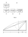
FIG 4 is a schematic diagram showing an equation corresponding to a mid-point algorithm. -
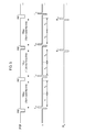
FIG 5 is a timing diagram showing an example of a pulse rate frequency, transmission of ultrasound signals and reception of the ultrasound signals. -
FIG 6 is a schematic diagram showing an example of transmitting and receiving the ultrasound signals based on the pulse rate frequency. -
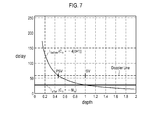
FIG 7 is a schematic diagram showing an example of a receive-focusing delay curve. - A detailed description may be provided with reference to the accompanying drawings. One of ordinary skill in the art may realize that the following description is illustrative only and is not in any way limiting.
- Referring to
FIG 1 , anultrasound system 100 in accordance with an illustrative embodiment is shown. As depicted therein, theultrasound system 100 includes auser input unit 110. - The
user input unit 110 is configured to receive input information. In the embodiment, the input information includes first input information for setting a sample volume SV on a brightness mode image BI, as shown inFIG 2 . InFIG 2 , reference numeral BV represents a blood vessel. The input information further includes second input information for selecting a high pulse rate frequency Doppler mode. However, it should be noted herein that the input information may not be limited thereto. Theuser input unit 110 includes a control panel, a trackball, a mouse, a keyboard and the like. - The
ultrasound system 100 further includes an ultrasounddata acquisition unit 120. Theultrasound acquisition unit 120 is configured to transmit ultrasound signals to a living body. The living body includes target objects (e.g., blood flow, a heart, etc.). Theultrasound acquisition unit 120 is further configured to receive ultrasound signals (i.e., ultrasound echo signals) from the living body to acquire ultrasound data. -
FIG 3 is a block diagram showing an illustrative embodiment of the ultrasound data acquisition unit. Referring toFIG 3 , the ultrasounddata acquisition unit 120 includes anultrasound probe 310. - The
ultrasound probe 310 includes a plurality of transducer elements (not shown) for reciprocally converting between ultrasound signals and electrical signals. Theultrasound probe 310 is configured to transmit the ultrasound signals to the living body. Theultrasound probe 310 is further configured to receive the ultrasound echo signals from the living body to output received signals. The received signals are analog signals. Theultrasound probe 310 includes a convex probe, a linear probe and the like. - The ultrasound
data acquisition unit 120 further includes a transmittingsection 320. The transmittingsection 320 is configured to control the transmission of the ultrasound signals. The transmittingsection 320 is further configured to generate electrical signals ("transmitting signals") for obtaining an ultrasound image in consideration of the elements and focusing points. The transmittingsection 320 includes a transmitting signal generating section (not shown), a transmitting delay time information memory (not shown), a transmitting beam former (not shown) and the like. - The ultrasound
data acquisition unit 120 further includes areceiving section 330. Thereceiving section 330 is configured to convert the received signals into digital signals. Thereceiving section 330 is further configured to apply delays to the digital signals in consideration of the elements and the focusing points to thereby output digital receive-focused signals. Thereceiving section 330 includes an analog-to-digital converter (not shown), a receiving delay time information memory (not shown), a receiving beam former (not shown) and the like. - The ultrasound
data acquisition unit 120 further includes an ultrasounddata forming section 340. The ultrasounddata forming section 340 is configured to form ultrasound data corresponding to the ultrasound image based on the digital receive-focused signals provided from thereceiving section 330. The ultrasound data includes radio frequency data or in-phase/quadrature data. However, it should be noted herein that the ultrasound data may not be limited thereto. The ultrasounddata forming section 340 is further configured to perform signal processing (e.g., gain control, etc) upon the digital receive-focused signals. - The ultrasound
data acquisition unit 120 will be described with reference to the accompanying drawings. For convenience of explanation, it is assumed that the sample volume is set at a depth of about 20cm and a phantom sample volume corresponding to the sample volume is set at a depth of about 10cm (i.e., a half of the depth corresponding to the sample volume) in depth direction of the brightness mode image BI. - The transmitting
section 320 is configured to generate first transmitting signals for obtaining the brightness mode image BI in consideration of the elements and the focusing points. - The
ultrasound probe 310 is configured to convert the first transmitting signals into the ultrasound signals, transmit the ultrasound signals to the living body and receive the ultrasound echo signals from the living body to thereby form first received signals. The receivingsection 330 is configured to convert the first received signals into first digital signals. The receivingsection 330 is configured to apply delays to the first digital signals based on a mid-point algorithm to thereby form first receive-focused signals. - Generally, the mid-point algorithm is a focusing delay algorithm, which is used to calculate a dynamic receive-focusing delay. The mid-point algorithm is defined as a conditional expression of
equation 1 provided below.
- In
FIG 1 , dn represents a decision function, rn represents an initial depth, and ln represents an initial delay value. That is, the ln represents a remaining distance obtained by subtracting the initial depth rn from the distance dn. The distance dn represents a distance from the focusing point to the Nth element. Also, α represents 2xsinθ shown inFIG 4 , Cn represents -4(α+1), and Cp represents -12-4α. - The Cn and Cp of the mid-point algorithm are determined by positions of the elements and the focusing points. Further, delay data of a receive-focusing delay curve are generated by the dn and rn of the mid-point algorithm.
- The ultrasound
data forming section 340 is configured to form first ultrasound data corresponding to the brightness mode image based on the first digital receive-focused signals provided from the receivingsection 330. The first ultrasound data includes radio frequency data. However, it should be noted herein that the first ultrasound data may not be limited thereto. - The transmitting
section 320 is configured to generate second transmitting signals for obtaining a high pulse rate frequency Doppler image corresponding to the high pulse rate frequency Doppler mode based on the input information (i.e., first input information and second input information) and a pulse rate frequency. Thus, theultrasound probe 310 is configured to convert the second transmitting signals provided from the transmittingsection 320 into the ultrasound signals, transmit the ultrasound signals to the living body and receive the ultrasound echo signals from the living body to form second received signals. - For example, the transmitting
section 320 is configured to generate the second transmitting signals based on a first pulse rate frequency PRF1. Theultrasound probe 310 is configured to convert the second transmitting signals provided from the transmittingsection 320 into the ultrasound signals and transmit the ultrasound signals (Tx1) based on the first pulse rate frequency PRF1, as shown inFIGs. 5 and6 . InFIG 6 , reference numeral PSV represents the phantom sample volume. After a T1 time, the ultrasound signals transmitted from theultrasound probe 310 are reached to the depth of 10cm, as shown inFIGs 5 and6 . After a T2 time, first ultrasound echo signals corresponding to the first pulse rate frequency PRF1 are received by theultrasound probe 310, and the ultrasound signals corresponding to the first pulse rate frequency PRF1 are reached to the depth of 20cm. The first ultrasound echo signals are ultrasound echo signals reflected from the depth of 10cm. Since the blood vessel does not exist at the depth of 10cm, blood flow information (e.g., blood flow velocity and the like) corresponding to the first ultrasound echo signals does not exist. - The transmitting
section 320 is configured to generate the second transmitting signals based on second pulse rate frequency PRF2. Theultrasound probe 310 is configured to convert the second transmitting signals into the ultrasound signals and transmit (Tx2) the ultrasound signals to the living body based on the second pulse rate frequency PRF2. Theultrasound probe 310 is further configured to receive (Rx1) the ultrasound echo signals reflected from the living body to form the second received signals, as shown inFIGs. 5 and6 . That is, theultrasound probe 310 transmits (Tx2) the ultrasound signals based on the second pulse rate frequency PRF2, as shown inFIGs. 5 and6 . After a T3 time, the ultrasound signals corresponding to the first pulse rate frequency PRF1 are reflected from the depth of 20cm, and the ultrasound signals corresponding to the second pulse rate frequency PRF2 are reached to the depth of 10cm. After a T4 time, second ultrasound echo signals corresponding to the first pulse rate frequency PRF1 are received by theultrasound probe 310, while third ultrasound echo signals corresponding to the second pulse rate frequency PRF2 are received by theultrasound probe 310. The second ultrasound echo signals are ultrasound echo signals reflected from the depth of 20cm. The third ultrasound echo signals are ultrasound echo signals reflected from the depth of 10cm. - The transmitting
section 310 is configured to generate the second transmitting signals based on third pulse rate frequency PRF3. Theultrasound probe 310 is configured to convert the second transmitting signals provided from the transmittingsection 310 into the ultrasound signals and transmit (Tx3) the ultrasound signals to the living body, as shown inFIGS. 5 and6 . Theultrasound probe 310 is further configured to receive (Rx2) the ultrasound echo signals from the living body as shown inFIGS. 5 and6 to thereby form second received signals. Referring toFIGS. 5 and6 , after a T5 time, the ultrasound signals corresponding to the second pulse rate frequency PRF2 are reflected from the depth of 20cm and are reached to the depth of 10cm. After a T6 time, fourth ultrasound echo signals corresponding to the second pulse rate frequency PRF2 are received by theultrasound probe 310. The fourth ultrasound echo signals are the ultrasound echo signals reflected from the depth of 20cm. - The receiving
section 330 is configured to convert the second received signals provided from theultrasound probe 310 into second digital signals. The receivingsection 330 is further configured to apply delay to the second digital signals based on the mid-point algorithm in accordance with the embodiment to form second digital receive-focused signals. - The receive-focused delay values are calculated by applying delay values throughout depths based on the mid-point algorithm calculates. However, the delay values throughout the depths are not needed since a pulse wave Doppler mode or the high pulse rate frequency Doppler mode acquires the ultrasound data by focusing a focusing point of a scan-line. Thus, the delay value corresponding to the sample volume SV is a valid delay value. When the delay value corresponding to the sample volume SV is applied to the depths, the delay value corresponding to the sample volume SV is used as the delay value corresponding to the phantom sample volume PSV
- The receiving
section 330 is configured to set an initial value of the dn in theequation 1 as 0 or under, and set an initial value of the Cn in theequation 1 as -8ln. When the initial values are set as mentioned above, a receive-focusing delay curve Iafter, which is identically held throughout the depths, is formed by the delay value ln, as shown inFIG 7 . InFIG 7 , reference numeral Ibefore represents the receiving focusing delay curve in accordance with the conventional mid-point algorithm. - Thus, the receiving
section 330 is configured to calculate a constant delay value throughout the depths by setting the dn and Cn so that the initial delay values are less than 0. The receivingsection 330 is further configured to apply the calculated delay value to the digital signals to form the digital receive-focused signals. - The ultrasound
data forming section 340 is configured to form second ultrasound data corresponding to the HPRF Doppler image based on the second digital receive-focused signals provided from the receivingsection 330. - Referring back to
FIG 1 , theultrasound system 100 further includes aprocessing unit 130 in communication with theuser input unit 110 and the ultrasounddata acquisition unit 120. Theprocessing unit 130 includes a central processing unit, a microprocessor, a graphic processing unit and the like. - In the embodiment, the
processing unit 130 forms the brightness mode image BI based on the first ultrasound data provided from the ultrasounddata acquisition unit 120. The brightness mode image BI is displayed on adisplay unit 150. Thus, a user sets the sample volume SV on the brightness mode image BI by using theuser input unit 110. Theprocessing unit 130 further sets the sample volume SV on the brightness mode image BI based on the input information (i.e., first input information) provided from theuser input unit 110. Theprocessing unit 130 further sets the phantom sample volume PSV on the brightness mode image BI based on the input information (i.e., second input information) provided from theuser input unit 110. Theprocessing unit 130 further forms Doppler signals based on the second ultrasound data provided from the ultrasounddata acquisition unit 120. Theprocessing unit 130 further forms the HPRF Doppler image based on the Doppler signals. - The
ultrasound system 100 further includes astorage unit 140. Thestorage unit 140 stores the ultrasound data (i.e., first ultrasound data and second ultrasound data) acquired by the ultrasounddata acquisition unit 120. Thestorage unit 140 further stores the input information received by theuser input unit 110. - The
ultrasound system 100 further includes thedisplay unit 150. Thedisplay unit 150 is configured to display the brightness mode image BI formed by theprocessing unit 130. Thedisplay unit 150 is further configured to display the HPRF Doppler image formed by theprocessing unit 130. - Although embodiments have been described with reference to a number of illustrative embodiments thereof, it should be understood that numerous other modifications and embodiments can be devised by those skilled in the art that will fall within the scope of the principles of this disclosure. More particularly, numerous variations and modifications are possible in the component parts and/or arrangements of the subject combination arrangement within the scope of the disclosure, the drawings and the appended claims. In addition to variations and modifications in the component parts and/or arrangements, alternative uses will also be apparent to those skilled in the art.
Claims (6)
- An ultrasound system, comprising:an ultrasound data acquisition unit configured to calculate a constant delay value throughout depths based on a sample volume by using a mid-point algorithm, transmit ultrasound signals to a living body, receive ultrasound echo signals from the living body and form digital signals based on the ultrasound echo signals, the ultrasound data acquisition unit being further configured to apply the constant delay value to the digital signals to acquire ultrasound data corresponding to a high pulse rate frequency Doppler image of the sample volume.
- The ultrasound system of Claim 1, wherein the ultrasound data acquisition unit comprises:a transmitting section configured to form an (i+1)th (i indicates a positive integer) transmitting signals for obtaining the high pulse rate frequency Doppler image based on a pulse rate frequency;an ultrasound probe configured to convert the (i+1)th transmitting signals into the ultrasound signals, transmit the ultrasound signals to the living body and receive ith ultrasound echo signals corresponding to ith transmitting signals from the living body to form received signals based on the pulse rate frequency;a receiving section configured to convert the received signals into the digital signals, set an initial setting value of the mid-point algorithm as 0 or under to calculate the constant delay value throughout the depths based on the sample volume, and apply the constant delay value to the digital signals to form digital receive-focused signals; andan ultrasound data forming section configured to form the ultrasound data based on the digital receive-focused signals.
- The ultrasound system of Claim 2, wherein the initial setting value includes an initial delay value.
- A method of performing a receive-focus based on a mid-point algorithm, comprising:a) calculating a constant delay value throughout depths based on a sample volume by using a mid-point algorithm;b) transmitting ultrasound signals to a living body and receiving ultrasound echo signals from the living body to form digital signals based on the ultrasound echo signals; andc) applying the constant delay value to the digital signals to acquire ultrasound data corresponding to a high pulse rate frequency Doppler image of the sample volume.
- The method of Claim 4, wherein the step a) comprises:setting an initial setting value of the mid-point algorithm as 0 or under to calculate the constant delay value throughout the depths based on the sample volume.
- The method of Claim 5, wherein the step b) comprises:forming an (i+1)th (i indicates a positive integer) transmitting signals for obtaining the high pulse rate frequency Doppler image based on a pulse rate frequency;converting the (i+1)th transmitting signals into the ultrasound signals;transmitting the ultrasound signals to the living body;receiving ith ultrasound echo signals corresponding to ith transmitting signals from the living body to form received signals based on the pulse rate frequency; andconverting the received signals into the digital signals.
Applications Claiming Priority (1)
| Application Number | Priority Date | Filing Date | Title |
|---|---|---|---|
| KR1020100128985A KR20120067535A (en) | 2010-12-16 | 2010-12-16 | Ultrasound system and method for providing high pulse rate frequency doppler image based on mid-point algorithm |
Publications (2)
| Publication Number | Publication Date |
|---|---|
| EP2466332A2 true EP2466332A2 (en) | 2012-06-20 |
| EP2466332A3 EP2466332A3 (en) | 2014-06-18 |
Family
ID=45350690
Family Applications (1)
| Application Number | Title | Priority Date | Filing Date |
|---|---|---|---|
| EP11193764.5A Withdrawn EP2466332A3 (en) | 2010-12-16 | 2011-12-15 | Performing receive-focusing based on mid-point algorithm in ultrasound system |
Country Status (4)
| Country | Link |
|---|---|
| US (1) | US9091760B2 (en) |
| EP (1) | EP2466332A3 (en) |
| JP (1) | JP2012125585A (en) |
| KR (1) | KR20120067535A (en) |
Families Citing this family (6)
| Publication number | Priority date | Publication date | Assignee | Title |
|---|---|---|---|---|
| US10667790B2 (en) | 2012-03-26 | 2020-06-02 | Teratech Corporation | Tablet ultrasound system |
| US9877699B2 (en) | 2012-03-26 | 2018-01-30 | Teratech Corporation | Tablet ultrasound system |
| KR102387708B1 (en) * | 2015-01-30 | 2022-04-19 | 삼성메디슨 주식회사 | Ultrasound System And Method For Providing Guide To Improve HPRF Doppler Image |
| JP6145202B1 (en) * | 2016-07-15 | 2017-06-07 | 株式会社日立製作所 | Ultrasonic diagnostic equipment |
| CN110167449A (en) | 2016-11-16 | 2019-08-23 | 德拉工业公司 | Portable ultrasound system |
| US11890132B2 (en) | 2020-02-28 | 2024-02-06 | Fujifilm Sonosite, Inc. | Detecting fluid flows using ultrasound imaging systems |
Family Cites Families (18)
| Publication number | Priority date | Publication date | Assignee | Title |
|---|---|---|---|---|
| US4182173A (en) * | 1978-08-23 | 1980-01-08 | General Electric Company | Duplex ultrasonic imaging system with repetitive excitation of common transducer in doppler modality |
| US5458129A (en) * | 1994-11-22 | 1995-10-17 | General Electric Company | Doppler dead zone avoidance |
| KR0143247B1 (en) * | 1995-02-06 | 1998-08-17 | 이민화 | Focusing method and apparatus for real time digital receiving |
| KR100252727B1 (en) * | 1997-02-04 | 2000-04-15 | 이민화 | Focus Delay Calculation Method and Device for Real-time Digital Focusing |
| JP4582827B2 (en) | 1998-02-10 | 2010-11-17 | 株式会社東芝 | Ultrasonic diagnostic equipment |
| US5961462A (en) * | 1998-05-18 | 1999-10-05 | Atl Ultrasound | Ultrasonic doppler imaging at high frame rates of display |
| JP4740436B2 (en) * | 1998-12-31 | 2011-08-03 | ゼネラル・エレクトリック・カンパニイ | Automatic adjustment of velocity scale and pulse repetition rate for Doppler ultrasound spectral photography |
| US6077226A (en) * | 1999-03-30 | 2000-06-20 | General Electric Company | Method and apparatus for positioning region of interest in image |
| US6213947B1 (en) * | 1999-03-31 | 2001-04-10 | Acuson Corporation | Medical diagnostic ultrasonic imaging system using coded transmit pulses |
| JP2001061840A (en) * | 1999-08-24 | 2001-03-13 | Matsushita Electric Ind Co Ltd | Ultrasound diagnostic equipment |
| US6364838B1 (en) * | 2000-01-11 | 2002-04-02 | Siemens Medical Soulutions, Usa, Inc. | Pulsed wave doppler processing using aliased spectral data |
| JP2003010183A (en) * | 2001-07-02 | 2003-01-14 | Matsushita Electric Ind Co Ltd | Ultrasound diagnostic equipment |
| US20030045797A1 (en) * | 2001-08-28 | 2003-03-06 | Donald Christopher | Automatic optimization of doppler display parameters |
| US6733454B1 (en) * | 2003-02-26 | 2004-05-11 | Siemens Medical Solutions Usa, Inc. | Automatic optimization methods and systems for doppler ultrasound imaging |
| US7128713B2 (en) * | 2003-07-10 | 2006-10-31 | Spentech, Inc. | Doppler ultrasound method and apparatus for monitoring blood flow and hemodynamics |
| EP1769747A4 (en) * | 2004-10-20 | 2008-04-09 | Toshiba Kk | DOPPLER DIAGNOSTIC ULTRASONIC DEVICE |
| CN102133107B (en) * | 2010-01-21 | 2014-10-15 | 深圳迈瑞生物医疗电子股份有限公司 | Method and device for improving HPRF (High-Pulse Repetition Frequency) performance in Doppler ultrasonic imaging |
| US8439840B1 (en) * | 2010-05-04 | 2013-05-14 | Sonosite, Inc. | Ultrasound imaging system and method with automatic adjustment and/or multiple sample volumes |
-
2010
- 2010-12-16 KR KR1020100128985A patent/KR20120067535A/en not_active Ceased
-
2011
- 2011-12-15 EP EP11193764.5A patent/EP2466332A3/en not_active Withdrawn
- 2011-12-15 JP JP2011274928A patent/JP2012125585A/en active Pending
- 2011-12-16 US US13/328,483 patent/US9091760B2/en active Active
Non-Patent Citations (1)
| Title |
|---|
| None |
Also Published As
| Publication number | Publication date |
|---|---|
| KR20120067535A (en) | 2012-06-26 |
| US20120157848A1 (en) | 2012-06-21 |
| US9091760B2 (en) | 2015-07-28 |
| JP2012125585A (en) | 2012-07-05 |
| EP2466332A3 (en) | 2014-06-18 |
Similar Documents
| Publication | Publication Date | Title |
|---|---|---|
| US8684934B2 (en) | Adaptively performing clutter filtering in an ultrasound system | |
| US10512452B2 (en) | Tissue characterization in medical diagnostic ultrasound | |
| US9261485B2 (en) | Providing color doppler image based on qualification curve information in ultrasound system | |
| EP2609871A1 (en) | Providing vector doppler image based on decision data in ultrasound system | |
| EP2609868A1 (en) | Providing user interface in ultrasound system | |
| EP0952462A2 (en) | Method and apparatus for improving visualization of biopsy needle in ultrasound imaging | |
| CN107049361B (en) | Sound velocity imaging using shear waves | |
| US9474510B2 (en) | Ultrasound and system for forming an ultrasound image | |
| EP2609870A1 (en) | Providing turbulent flow information based on vector doppler in ultrasound system | |
| US9091760B2 (en) | Performing receive-focusing based on mid-point algorithm in ultrasound system | |
| EP2550919A1 (en) | Ultrasound system and method for correcting doppler angle | |
| EP2245988A1 (en) | Clutter signal filtering using eigenvectors in an ultrasound system | |
| US9232932B2 (en) | Providing motion mode image in ultrasound system | |
| EP2462872A1 (en) | Providing additional information corresponding to change of blood flow with a time in ultrasound system | |
| EP2610638A2 (en) | Forming vector information based on vector doppler in ultrasound system | |
| US9474503B2 (en) | Ultrasound system and method for detecting vector information using transmission delays | |
| EP2609869A1 (en) | Providing particle flow image in ultrasound system | |
| EP2386251A1 (en) | Providing at least one slice image with additional information in an ultrasound system | |
| US11452503B2 (en) | Shear wave imaging based on ultrasound with increased pulse repetition frequency | |
| EP2380498A1 (en) | Adaptive clutter filtering in an ultrasound system | |
| KR101117900B1 (en) | Ultrasound system and method for setting eigenvectors | |
| EP2238912A2 (en) | Ultrasound system and method of providing color M mode image and brightness M mode image | |
| Bar-Zion et al. | Towards sub-Nyquist tissue Doppler imaging using non-uniformly spaced stream of pulses |
Legal Events
| Date | Code | Title | Description |
|---|---|---|---|
| PUAI | Public reference made under article 153(3) epc to a published international application that has entered the european phase |
Free format text: ORIGINAL CODE: 0009012 |
|
| AK | Designated contracting states |
Kind code of ref document: A2 Designated state(s): AL AT BE BG CH CY CZ DE DK EE ES FI FR GB GR HR HU IE IS IT LI LT LU LV MC MK MT NL NO PL PT RO RS SE SI SK SM TR |
|
| AX | Request for extension of the european patent |
Extension state: BA ME |
|
| PUAL | Search report despatched |
Free format text: ORIGINAL CODE: 0009013 |
|
| AK | Designated contracting states |
Kind code of ref document: A3 Designated state(s): AL AT BE BG CH CY CZ DE DK EE ES FI FR GB GR HR HU IE IS IT LI LT LU LV MC MK MT NL NO PL PT RO RS SE SI SK SM TR |
|
| AX | Request for extension of the european patent |
Extension state: BA ME |
|
| RIC1 | Information provided on ipc code assigned before grant |
Ipc: G01S 7/52 20060101ALI20140515BHEP Ipc: G10K 11/34 20060101ALI20140515BHEP Ipc: G01S 15/89 20060101AFI20140515BHEP |
|
| 17P | Request for examination filed |
Effective date: 20141218 |
|
| RBV | Designated contracting states (corrected) |
Designated state(s): AL AT BE BG CH CY CZ DE DK EE ES FI FR GB GR HR HU IE IS IT LI LT LU LV MC MK MT NL NO PL PT RO RS SE SI SK SM TR |
|
| 17Q | First examination report despatched |
Effective date: 20161010 |
|
| STAA | Information on the status of an ep patent application or granted ep patent |
Free format text: STATUS: THE APPLICATION IS DEEMED TO BE WITHDRAWN |
|
| 18D | Application deemed to be withdrawn |
Effective date: 20170421 |