EP2466207A2 - Fuel atomization dual orifice fuel nozzle - Google Patents
Fuel atomization dual orifice fuel nozzle Download PDFInfo
- Publication number
- EP2466207A2 EP2466207A2 EP11191658A EP11191658A EP2466207A2 EP 2466207 A2 EP2466207 A2 EP 2466207A2 EP 11191658 A EP11191658 A EP 11191658A EP 11191658 A EP11191658 A EP 11191658A EP 2466207 A2 EP2466207 A2 EP 2466207A2
- Authority
- EP
- European Patent Office
- Prior art keywords
- pilot
- fuel
- annular
- swirler
- primary
- Prior art date
- Legal status (The legal status is an assumption and is not a legal conclusion. Google has not performed a legal analysis and makes no representation as to the accuracy of the status listed.)
- Withdrawn
Links
Images


Classifications
-
- F—MECHANICAL ENGINEERING; LIGHTING; HEATING; WEAPONS; BLASTING
- F23—COMBUSTION APPARATUS; COMBUSTION PROCESSES
- F23R—GENERATING COMBUSTION PRODUCTS OF HIGH PRESSURE OR HIGH VELOCITY, e.g. GAS-TURBINE COMBUSTION CHAMBERS
- F23R3/00—Continuous combustion chambers using liquid or gaseous fuel
- F23R3/28—Continuous combustion chambers using liquid or gaseous fuel characterised by the fuel supply
- F23R3/283—Attaching or cooling of fuel injecting means including supports for fuel injectors, stems, or lances
-
- F—MECHANICAL ENGINEERING; LIGHTING; HEATING; WEAPONS; BLASTING
- F23—COMBUSTION APPARATUS; COMBUSTION PROCESSES
- F23D—BURNERS
- F23D11/00—Burners using a direct spraying action of liquid droplets or vaporised liquid into the combustion space
- F23D11/36—Details, e.g. burner cooling means, noise reduction means
- F23D11/38—Nozzles; Cleaning devices therefor
- F23D11/383—Nozzles; Cleaning devices therefor with swirl means
-
- F—MECHANICAL ENGINEERING; LIGHTING; HEATING; WEAPONS; BLASTING
- F23—COMBUSTION APPARATUS; COMBUSTION PROCESSES
- F23D—BURNERS
- F23D11/00—Burners using a direct spraying action of liquid droplets or vaporised liquid into the combustion space
- F23D11/36—Details, e.g. burner cooling means, noise reduction means
- F23D11/38—Nozzles; Cleaning devices therefor
- F23D11/386—Nozzle cleaning
-
- F—MECHANICAL ENGINEERING; LIGHTING; HEATING; WEAPONS; BLASTING
- F23—COMBUSTION APPARATUS; COMBUSTION PROCESSES
- F23R—GENERATING COMBUSTION PRODUCTS OF HIGH PRESSURE OR HIGH VELOCITY, e.g. GAS-TURBINE COMBUSTION CHAMBERS
- F23R3/00—Continuous combustion chambers using liquid or gaseous fuel
- F23R3/28—Continuous combustion chambers using liquid or gaseous fuel characterised by the fuel supply
- F23R3/286—Continuous combustion chambers using liquid or gaseous fuel characterised by the fuel supply having fuel-air premixing devices
-
- F—MECHANICAL ENGINEERING; LIGHTING; HEATING; WEAPONS; BLASTING
- F23—COMBUSTION APPARATUS; COMBUSTION PROCESSES
- F23R—GENERATING COMBUSTION PRODUCTS OF HIGH PRESSURE OR HIGH VELOCITY, e.g. GAS-TURBINE COMBUSTION CHAMBERS
- F23R3/00—Continuous combustion chambers using liquid or gaseous fuel
- F23R3/28—Continuous combustion chambers using liquid or gaseous fuel characterised by the fuel supply
- F23R3/36—Supply of different fuels
-
- F—MECHANICAL ENGINEERING; LIGHTING; HEATING; WEAPONS; BLASTING
- F23—COMBUSTION APPARATUS; COMBUSTION PROCESSES
- F23R—GENERATING COMBUSTION PRODUCTS OF HIGH PRESSURE OR HIGH VELOCITY, e.g. GAS-TURBINE COMBUSTION CHAMBERS
- F23R2900/00—Special features of, or arrangements for continuous combustion chambers; Combustion processes therefor
- F23R2900/00004—Preventing formation of deposits on surfaces of gas turbine components, e.g. coke deposits
-
- F—MECHANICAL ENGINEERING; LIGHTING; HEATING; WEAPONS; BLASTING
- F23—COMBUSTION APPARATUS; COMBUSTION PROCESSES
- F23R—GENERATING COMBUSTION PRODUCTS OF HIGH PRESSURE OR HIGH VELOCITY, e.g. GAS-TURBINE COMBUSTION CHAMBERS
- F23R2900/00—Special features of, or arrangements for continuous combustion chambers; Combustion processes therefor
- F23R2900/03042—Film cooled combustion chamber walls or domes
-
- F—MECHANICAL ENGINEERING; LIGHTING; HEATING; WEAPONS; BLASTING
- F23—COMBUSTION APPARATUS; COMBUSTION PROCESSES
- F23R—GENERATING COMBUSTION PRODUCTS OF HIGH PRESSURE OR HIGH VELOCITY, e.g. GAS-TURBINE COMBUSTION CHAMBERS
- F23R2900/00—Special features of, or arrangements for continuous combustion chambers; Combustion processes therefor
- F23R2900/03044—Impingement cooled combustion chamber walls or subassemblies
-
- Y—GENERAL TAGGING OF NEW TECHNOLOGICAL DEVELOPMENTS; GENERAL TAGGING OF CROSS-SECTIONAL TECHNOLOGIES SPANNING OVER SEVERAL SECTIONS OF THE IPC; TECHNICAL SUBJECTS COVERED BY FORMER USPC CROSS-REFERENCE ART COLLECTIONS [XRACs] AND DIGESTS
- Y02—TECHNOLOGIES OR APPLICATIONS FOR MITIGATION OR ADAPTATION AGAINST CLIMATE CHANGE
- Y02T—CLIMATE CHANGE MITIGATION TECHNOLOGIES RELATED TO TRANSPORTATION
- Y02T50/00—Aeronautics or air transport
- Y02T50/60—Efficient propulsion technologies, e.g. for aircraft
Definitions
- the present invention relates to gas turbine engine fuel nozzles and, more particularly, to such fuel nozzles having pilot fuel injector tips containing dual orifice pilot fuel nozzles.
- Aircraft gas turbine engine staged combustion systems have been developed to limit the production of undesirable combustion product components such as oxides of nitrogen (NOx), unburned hydrocarbons (HC), and carbon monoxide (CO) particularly in the vicinity of airports, where they contribute to urban photochemical smog problems.
- Gas turbine engines also are designed to be fuel efficient and have a low cost of operation.
- Other factors that influence combustor design are the desires of users of gas turbine engines for efficient, low cost operation, which translates into a need for reduced fuel consumption while at the same time maintaining or even increasing engine output.
- important design criteria for aircraft gas turbine engine combustion systems include provisions for high combustion temperatures, in order to provide high thermal efficiency under a variety of engine operating conditions, as well as minimizing undesirable combustion conditions that contribute to the emission of particulates, and to the emission of undesirable gases, and to the emission of combustion products that are precursors to the formation of photochemical smog.
- TAPS twin annular premixing swirler
- the TAPS mixer assembly includes a pilot mixer which is supplied with fuel during the entire engine operating cycle and a main mixer which is supplied with fuel only during increased power conditions of the engine operating cycle. While improvements in the main mixer of the assembly during high power conditions (i.e., take-off and climb) are disclosed in patent applications having Serial Nos.
- a pilot fuel injector tip for use in a gas turbine engine fuel nozzle assembly includes substantially concentric primary and secondary pilot fuel nozzles centered about a centerline axis of the pilot fuel injector tip.
- the primary and secondary pilot fuel nozzles having circular primary and annular secondary exits respectively and the circular primary exit is located axially aft and downstream of the annular secondary exit.
- An annular secondary fuel supply passage operable for flowing fuel to the annular secondary exit in the secondary pilot fuel nozzle may include an annular secondary fuel swirler having an annular array of helical spin slots which may have rectangular cross sections.
- a fuel nozzle assembly including the pilot fuel injector tip has an annular inwardly tapering conical flowpath section of a pilot swirler flowpath section, a first downstream end of the primary pilot fuel nozzle including the circular primary exit, and a second downstream end of the secondary pilot fuel nozzle including the annular secondary exit.
- the annular inwardly tapering conical flowpath section surrounds the first and second downstream ends and an inwardly tapering conical wall section radially inwardly bounds the annular inwardly tapering conical flowpath section and defines a conical surface.
- the circular primary and annular secondary exits are located at or axially forward or upstream of the conical surface.
- the fuel nozzle assembly may include an inner pilot swirler located radially outwardly of and adjacent to the dual orifice pilot fuel injector tip, an outer pilot swirler located radially outwardly of the inner swirler, an axially aftwardly or downstream extending injector cooling flowpath disposed radially outwardly of and surrounding the second pilot swirler, an annular wall section radially disposed between the outer pilot swirler and an annular cooling flowpath inlet to the injector cooling flowpath, an annular chamfered leading edge of the annular wall section, and a radially inwardly facing conical chamfered surface of the chamfered leading edge for diverting dirt away from the cooling flowpath inlet to the injector cooling flowpath.
- the injector cooling flowpath may be disposed in a pilot housing including a centerbody radially surrounding the pilot mixer.
- the injector cooling flowpath is radially disposed between a fuel nozzle inner casing and the centerbody.
- An upstream forward end of the centerbody includes an annular chamfered leading edge of the forward end and a radially inwardly facing conical chamfered surface of the chamfered leading edge.
- FIG. 1 Illustrated in FIG. 1 is an exemplary embodiment of a combustor 16 including a combustion zone 18 defined between and by annular radially outer and inner liners 20, 22, respectively circumscribed about an engine centerline 52.
- the outer and inner liners 20, 22 are located radially inwardly of an annular combustor casing 26 which extends circumferentially around outer and inner liners 20, 22.
- the combustor 16 also includes an annular dome 34 mounted upstream of the combustion zone 18 and attached to the outer and inner liners 20, 22.
- the dome 34 defines an upstream end 36 of the combustion zone 18 and a plurality of mixer assemblies 40 (only one is illustrated) are spaced circumferentially around the dome 34.
- Each mixer assembly 40 includes a main mixer 104 mounted in the dome 34 and a pilot mixer 102.
- the combustor 16 receives an annular stream of pressurized compressor discharge air 14 from a high pressure compressor discharge outlet 69 at what is referred to as CDP air (compressor discharge pressure air).
- CDP air compressor discharge pressure air
- a first portion 23 of the compressor discharge air 14 flows into the mixer assembly 40, where fuel is also injected to mix with the air and form a fuel-air mixture 65 that is provided to the combustion zone 18 for combustion. Ignition of the fuel-air mixture 65 is accomplished by a suitable igniter 70, and the resulting combustion gases 60 flow in an axial direction toward and into an annular, first stage turbine nozzle 72.
- the first stage turbine nozzle 72 is defined by an annular flow channel that includes a plurality of radially extending, circularly-spaced nozzle vanes 74 that turn the gases so that they flow angularly and impinge upon the first stage turbine blades (not shown) of a first turbine (not shown).
- FIG. 1 illustrate the directions in which compressor discharge air flows within combustor 16.
- a second portion 24 of the compressor discharge air 14 flows around the outer liner 20 and a third portion 25 of the compressor discharge air 14 flows around the inner liner 22.
- a fuel injector 10, further illustrated in FIG. 2 includes a nozzle mount or flange 30 adapted to be fixed and sealed to the combustor casing 26.
- a hollow stem 32 of the fuel injector 10 is integral with or fixed to the flange 30 (such as by brazing or welding) and includes a fuel nozzle assembly 12.
- the hollow stem 32 supports the fuel nozzle assembly 12 and the pilot mixer 102.
- a valve housing 37 at the top of the stem 32 contains valves illustrated and discussed in more detail in United States Patent Application No. 20100263382 , referenced above.
- the fuel nozzle assembly 12 includes a main fuel nozzle 61 and an annular pilot inlet 54 to the pilot mixer 102 through which the first portion 23 of the compressor discharge air 14 flows.
- the fuel nozzle assembly 12 further includes a dual orifice pilot fuel injector tip 57 substantially centered in the annular pilot inlet 54.
- the dual orifice pilot fuel injector tip 57 includes concentric primary and secondary pilot fuel nozzles 58, 59.
- the pilot mixer 102 includes a centerline axis 120 about which the dual orifice pilot fuel injector tip 57, the primary and secondary pilot fuel nozzles 58, 59, the annular pilot inlet 54 and the main fuel nozzle 61 are centered and circumscribed.
- the main fuel nozzle 61 is spaced radially outwardly of the primary and secondary pilot fuel nozzles 58, 59.
- the secondary pilot fuel nozzle 59 is radially located directly adjacent to and surrounds the primary pilot fuel nozzle 58.
- the primary and secondary pilot fuel nozzles 58, 59 and main fuel nozzle 61 and the mixer assembly 40 are used to deliver the fuel air mixture 65 to the combustion zone 18.
- the main fuel nozzle 61 includes a circular or annular array of radially outwardly open fuel injection orifices 63.
- a fuel nozzle outer casing 71 surrounds the main fuel nozzle 61 and includes cylindrical fuel spray holes 73 aligned with the fuel injection orifices 63.
- a pilot housing 99 includes a centerbody 103 and radially inwardly supports the pilot fuel injector tip 57 and radially outwardly supports the main fuel nozzle 61.
- the centerbody 103 is radially disposed between the pilot fuel injector tip 57 and the main fuel nozzle 61.
- the centerbody 103 surrounds the pilot mixer 102 and defines a chamber 105 that is in flow communication with, and downstream from, the pilot mixer 102.
- the pilot mixer 102 radially supports the dual orifice pilot fuel injector tip 57 at a radially inner diameter ID and the centerbody 103 radially supports the main fuel nozzle 61 at a radially outer diameter OD with respect to the engine centerline 52.
- the main fuel nozzle 61 is disposed within the main mixer 104 (illustrated in FIG. 1 ) of the mixer assembly 40 and the dual orifice pilot fuel injector tip 57 is disposed within the pilot mixer 102.
- the pilot mixer 102 includes an inner pilot swirler 112 located radially outwardly of and adjacent to the dual orifice pilot fuel injector tip 57, an outer pilot swirler 114 located radially outwardly of the inner pilot swirler 112, and a swirler splitter 116 positioned therebetween.
- the swirler splitter 116 extends downstream of the dual orifice pilot fuel injector tip 57 and a venturi 118 is formed in a downstream portion 115 of the swirler splitter 116.
- the venturi 118 includes a converging section 117, a diverging section 119, and a throat 121 therebetween.
- the throat 121 is located downstream of a primary exit 98 of the primary pilot fuel nozzle 58.
- the inner and outer pilot swirlers 112, 114 are generally oriented parallel to the centerline axis 120 of the dual orifice pilot fuel injector tip 57 and the mixing assembly 40.
- the inner and outer pilot swirlers 112, 114 include a plurality of swirling vanes 44 for swirling air traveling therethrough. Fuel and air are provided to pilot mixer 102 at all times during the engine operating cycle so that a primary combustion zone 122 (illustrated in FIG. 1 ) is produced within a central portion of combustion zone 18.
- the primary and secondary pilot fuel nozzles 58, 59 have circular primary and annular secondary exits 98, 100 respectively, are operable to inject fuel in a generally downstream direction, and are often referred to as a dual orifice nozzle.
- the main fuel nozzle 61 is operable to inject fuel in a generally radially outwardly direction through the circular array of radially outwardly open fuel injection orifices 63.
- the primary pilot fuel nozzle 58 includes a primary fuel supply passage 158 which feeds fuel to the circular primary exit 98 at a first downstream end 142 of the primary pilot fuel nozzle 58.
- the secondary pilot fuel nozzle 59 includes an annular secondary fuel supply passage 159 which flows fuel to the annular secondary exit 100 at a second downstream end 143 of the secondary pilot fuel nozzle 59.
- a primary fuel swirler 136 adjacent the downstream end 142 of the primary fuel supply passage 158 is used to swirl the fuel flow exiting the circular primary exit 98.
- the exemplary primary fuel swirler 136 illustrated herein is a cylindrical plug having downstream and circumferentially angled fuel injection holes 164 to pre-film a conical primary exit orifice 166 of the primary pilot fuel nozzle 58 with fuel which improves atomization of the fuel.
- the conical primary exit orifice 166 culminates at the circular primary exit 98.
- the primary fuel swirler 136 swirls the fuel and centrifugal force of the swirling fuel forces the fuel against a primary conical surface 168 of the conical primary exit orifice 166 thus pre-filming the fuel along the primary conical surface 168.
- annular secondary fuel swirler 137 in the annular secondary fuel supply passage 159 adjacent the downstream end 143 of the secondary pilot fuel nozzle 59 is used to swirl the fuel flow exiting the annular secondary exit 100.
- the exemplary secondary fuel swirler 137 is an annular array 180 of helical spin slots 182 operable to pre-film a conical secondary exit orifice 167 of the secondary pilot fuel nozzle 59 with fuel which improves atomization of the fuel.
- the helical spin slots 182 are illustrated herein as having a rectangular cross section 183 with respect to fuel flow direction through the helical spin slots 182.
- the conical secondary exit orifice 167 culminates at the annular secondary exit 100.
- the secondary fuel swirler 137 swirls the fuel and centrifugal force of the swirling fuel forces it against a secondary conical surface 169 of the conical secondary exit orifice 167 thus pre-filming the fuel along the secondary conical surface 169.
- Concentric annular primary and secondary fuel films from the concentric primary and secondary pilot fuel nozzles 58, 59 respectively merge together and the combined fuel is atomized by an air stream from the pilot mixer 102 which is at its maximum velocity in a plane in the vicinity of the annular secondary exit 100.
- the circular primary exit 98 is located axially aft and downstream of the annular secondary exit 100. This results in physically separating the primary and secondary fuel films after they are ejected from the concentric primary and secondary pilot fuel nozzles 58, 59.
- This separation better positions the fuel films within a shear layer of inner pilot swirler flow 138 from the inner pilot swirler 112 and improves fuel atomization and reduces intermittency in the overall spray quality over a wide-range of engine operating conditions. This also allows an accurate placement of fuel close to the shear layers to provide maximum flexibility which in turn plays a major role in emissions and engine operability over a range of engine operating conditions.
- Locating the circular primary exit 98 axially aft and downstream of the annular secondary exit 100 allows the pre-filming primary conical surface 168 of the conical primary exit orifice 166 of the primary pilot fuel nozzle 58 and the secondary conical surface 169 of the conical secondary exit orifice 167 of the secondary pilot fuel nozzle 59 to release fuel closest to the incoming shear layer and do so consistently for a variety of fueling modes and engine operating conditions.
- the inner pilot swirler 112 has a generally cylindrical inner pilot swirler flowpath section 222 followed by an annular inwardly tapering conical flowpath section 224 between the swirler splitter 116 and a radially outer wall 226 of the pilot fuel injector tip 57.
- the conical flowpath section 224 surrounds the first downstream end 142 of the primary pilot fuel nozzle 58 including the circular primary exit 98.
- the conical flowpath section 224 also surrounds secondary the second downstream end 143 of the secondary pilot fuel nozzle 59 including the annular secondary exit 100.
- the inwardly tapering conical flowpath section 224 is radially inwardly bounded by an inwardly tapering conical wall section 230 of the radially outer wall 226 in the converging section 117 of the venturi 118. Illustrated in FIG. 6 is a conical surface 232 in space defined by the inwardly tapering conical wall section 230.
- the circular primary and annular secondary exits 98, 100 may be axially located substantially up to but not axially aft or downstream of the conical surface 232 in order to release fuel closest to the incoming shear layer and do so consistently for a variety of fueling modes and engine operating conditions.
- a cross over arm 56 extends radially across the annular pilot inlet 54 from the main fuel nozzle 61 to the pilot fuel injector tip 57.
- the cross over arm 56 includes an aerodynamically drag reducing cross over arm fairing 62, or tube, surrounding primary and secondary fuel transfer tubes 64, 66 used to transfer fuel across the annular pilot inlet 54 to the primary and secondary fuel supply passages 158, 159 respectively in the pilot fuel injector tip 57.
- the cross over arm fairing 62 includes rounded leading and trailing edges 80, 82 and generally flat and generally circumferentially spaced apart flat first and second sides 67, 68 defining a rectangular middle section 76 extending between the rounded leading and trailing edges 80, 82.
- the rounded leading and trailing edges 80, 82 illustrated herein are semi-cylindrical.
- the rounded leading edge 80 is representative of a rounded forebody 46 and the rectangular middle section 76 with the spaced apart flat first and second sides 67, 68 is representative of a straight afterbody 48.
- an aerodynamically drag reducing pilot nose cap 53 also referred to as a bullet nose or rounded nose is located at an upstream end 55 of the pilot fuel injector tip 57.
- the pilot nose cap 53 includes a rounded or more specifically a generally oval shaped nose base 77 and a substantially rounded dome 78 extending forwardly or upstream from the nose base 77.
- a cylindrical nose afterbody 92 or more specifically a substantially oval cylindrical nose afterbody 92 extends axially aft or downstream from the nose base 77.
- the nose afterbody 92 is centered about and parallel to a pilot nose centerline 111 perpendicular or normal to the nose base 77.
- the rounded dome 78 is representative of a rounded forebody 46 and the nose afterbody 92 is representative of a straight afterbody 48.
- the pilot nose centerline 111 is illustrated herein as collinear with the centerline axis 120 about which the pilot fuel injector tip 57 is centered and circumscribed.
- the pilot nose centerline 111 may be angled and/or slightly offset with respect to the centerline axis 120 to more evenly distribute and align pilot airflow 101 flowing into the pilot mixer 102 and its inner and outer pilot swirlers 112, 114.
- the pilot nose centerline 111 may be angled up to about 10 degrees with respect to the centerline axis 120.
- the pilot nose cap 53 includes a generally oval shaped nose base 77 and a substantially rounded dome 78 extending forwardly or upstream from the nose base 77.
- the dome 78 is illustrated herein as a generally oval rounded dome having a slight blunted or flat top 86.
- the nose base 77 has a generally oval perimeter 88 with circular first and second end segments 106, 108 connected by spaced apart substantially curved side segments 109.
- the circular first and second end segments 106, 108 are mirror image arcs having first radii R1.
- the exemplary curved side segments 109 are illustrated herein as being generally mirror image arcs having second radii R2 substantially greater than the first radii R1.
- the exemplary curved side segments 109 illustrated herein also include straight middle sections 113 centered in the curved side segments 109.
- a center conical section 90 of the dome 78 extends forwardly or upstream from the straight middle sections 113 of the curved side segments 109 and illustrated herein as having a rectangular flat top 86.
- the nose afterbody 92 is illustrated as having oval cross sectional shape matching the oval perimeter 88 of the nose base 77.
- the nose afterbody 92 extends aft or downstream from and at substantially 90 degrees from or normal to the nose base 77.
- the nose afterbody 92 includes spaced apart rounded first and second ends 146, 148 corresponding to the circular first and second end segments 106, 108.
- the nose afterbody 92 further includes spaced apart generally curved sides 409 corresponding to the curved side segments 109 of the oval perimeter 88.
- the exemplary embodiment of the nose afterbody 92 illustrated herein also includes a rectangular middle section 149 disposed between the rounded first and second ends 146, 148.
- the rectangular middle section 149 includes spaced apart flat sides 152 corresponding to the straight middle sections 113 of the oval perimeter 88.
- the curved and flat sides 409, 152 extend aft or downstream from the curved side segments 109 and straight middle sections 113 respectively of the oval perimeter 88.
- the cross over arm fairing 62 and the pilot nose cap 53 are both example of fuel injector fairings designed to minimize flow obstruction, avoid asymmetric flow, and maximize the pilot airflow 101 through the pilot mixer 102 and its inner and outer pilot swirlers 112, 114.
- the fuel injector fairings are designed to promote pilot flame stabilization by increasing pilot inner swirl number and improve pilot atomization by increasing pilot air velocity of the pilot airflow 101.
- the cross over arm fairing 62 and the pilot nose cap 53 have rounded forebodies 46 followed by straight afterbodies 48.
- the exemplary embodiment of the fuel nozzle assembly 12 illustrated herein depicts the straight afterbodies 48 as being parallel to the pilot nose centerline 111.
- an axially or downstream extending injector cooling flowpath 190 is disposed in the pilot housing 99 and radially between a fuel nozzle inner casing 79 and the centerbody 103.
- the main fuel nozzle 61 is radially disposed outwardly of and supported at least in part by the fuel nozzle inner casing 79.
- the injector cooling flowpath 190 extends axially downstream or aft from the annular pilot inlet 54 to an aft annular plenum 192 at an aft end 194 of the injector cooling flowpath 190.
- the aft annular plenum 192 includes an annular groove, slot, or pocket 195 in a radially outwardly extending aft flange 196 of the fuel nozzle inner casing 79 and is radially inwardly bounded by the centerbody 103.
- Cooling holes 198 through an axially aft annular wall 200 of the aft flange 196 direct cooling air from the aft annular plenum 192 onto a radially outwardly extending aft heat shield flange 197 on an aft end 202 of the centerbody 103.
- An annular heat shield 204 faces the combustion zone 18 and is mounted on the heat shield flange 197.
- An annular cooling flowpath inlet 206 to the injector cooling flowpath 190 is radially inwardly bounded by the centerbody 103.
- An upstream forward end 208 of the centerbody 103 is radially disposed between the outer pilot swirler 114 and the centerbody 103 and operates as a flow splitter between the outer pilot swirler 114 and the annular cooling flowpath inlet 206 to the injector cooling flowpath 190.
- the forward end 208 of the centerbody 103 is an annular wall section including an annular chamfered leading edge 210 having a radially inwardly facing conical chamfered surface 212.
- the chamfered leading edge 210 operates as a dirt deflector that diverts dirt in the pilot airflow 101 away from the cooling flowpath inlet 206.
Abstract
Description
- The present invention relates to gas turbine engine fuel nozzles and, more particularly, to such fuel nozzles having pilot fuel injector tips containing dual orifice pilot fuel nozzles.
- Aircraft gas turbine engine staged combustion systems have been developed to limit the production of undesirable combustion product components such as oxides of nitrogen (NOx), unburned hydrocarbons (HC), and carbon monoxide (CO) particularly in the vicinity of airports, where they contribute to urban photochemical smog problems. Gas turbine engines also are designed to be fuel efficient and have a low cost of operation. Other factors that influence combustor design are the desires of users of gas turbine engines for efficient, low cost operation, which translates into a need for reduced fuel consumption while at the same time maintaining or even increasing engine output. As a consequence, important design criteria for aircraft gas turbine engine combustion systems include provisions for high combustion temperatures, in order to provide high thermal efficiency under a variety of engine operating conditions, as well as minimizing undesirable combustion conditions that contribute to the emission of particulates, and to the emission of undesirable gases, and to the emission of combustion products that are precursors to the formation of photochemical smog.
- One mixer design that has been utilized is known as a twin annular premixing swirler (TAPS), which is disclosed in the following
U.S. Patent Nos. 6,354,072 ;6,363,726 ;6,367,262 ;6,381,964 ;6,389,815 ;6,418,726 ;6,453,660 ;6,484,489 ; and,6,865,889 . It will be understood that the TAPS mixer assembly includes a pilot mixer which is supplied with fuel during the entire engine operating cycle and a main mixer which is supplied with fuel only during increased power conditions of the engine operating cycle. While improvements in the main mixer of the assembly during high power conditions (i.e., take-off and climb) are disclosed in patent applications having Serial Nos.11/188,596 11/188,598 11/188,470 U.S. Patent No. 7,762,073 , entitled "Pilot Mixer For Mixer Assembly Of A Gas Turbine Engine Combustor Having A Primary Fuel Injector And A Plurality Of Secondary Fuel Injection Ports" which issued July 27, 2010. This patent is owned by the assignee of the present application and hereby incorporated by reference. - United States Patent Application No. Serial No.:
12/424,612 20100263382 ), filed April 16, 2009, entitled "DUAL ORIFICE PILOT FUEL INJECTOR" discloses a fuel nozzle having first second pilot fuel nozzles designed to improve sub-idle efficiency, reduced circumferential exhaust gas temperature (EGT) variation while maintaining a low susceptibility to coking of the fuel injectors. This patent application is owned by the assignee of the present application and hereby incorporated by reference. - It is highly desirable to improve the operating efficiency of fuel nozzles. More particularly, it is highly desirable to optimize pilot fuel atomization which also improves flame stabilization. It is also highly desirable to reduce intermittency in the overall pilot fuel spray quality over a wide-range of engine operating conditions.
- A pilot fuel injector tip for use in a gas turbine engine fuel nozzle assembly includes substantially concentric primary and secondary pilot fuel nozzles centered about a centerline axis of the pilot fuel injector tip. The primary and secondary pilot fuel nozzles having circular primary and annular secondary exits respectively and the circular primary exit is located axially aft and downstream of the annular secondary exit.
- An annular secondary fuel supply passage operable for flowing fuel to the annular secondary exit in the secondary pilot fuel nozzle may include an annular secondary fuel swirler having an annular array of helical spin slots which may have rectangular cross sections.
- A fuel nozzle assembly including the pilot fuel injector tip has an annular inwardly tapering conical flowpath section of a pilot swirler flowpath section, a first downstream end of the primary pilot fuel nozzle including the circular primary exit, and a second downstream end of the secondary pilot fuel nozzle including the annular secondary exit. The annular inwardly tapering conical flowpath section surrounds the first and second downstream ends and an inwardly tapering conical wall section radially inwardly bounds the annular inwardly tapering conical flowpath section and defines a conical surface. The circular primary and annular secondary exits are located at or axially forward or upstream of the conical surface.
- The fuel nozzle assembly may include an inner pilot swirler located radially outwardly of and adjacent to the dual orifice pilot fuel injector tip, an outer pilot swirler located radially outwardly of the inner swirler, an axially aftwardly or downstream extending injector cooling flowpath disposed radially outwardly of and surrounding the second pilot swirler, an annular wall section radially disposed between the outer pilot swirler and an annular cooling flowpath inlet to the injector cooling flowpath, an annular chamfered leading edge of the annular wall section, and a radially inwardly facing conical chamfered surface of the chamfered leading edge for diverting dirt away from the cooling flowpath inlet to the injector cooling flowpath.
- The injector cooling flowpath may be disposed in a pilot housing including a centerbody radially surrounding the pilot mixer. The injector cooling flowpath is radially disposed between a fuel nozzle inner casing and the centerbody. An upstream forward end of the centerbody includes an annular chamfered leading edge of the forward end and a radially inwardly facing conical chamfered surface of the chamfered leading edge.
- The foregoing aspects and other features of the invention are explained in the following description, taken in connection with the accompanying drawings where:
-
FIG. 1 is a cross-sectional view illustration of a gas turbine engine combustor with an exemplary embodiment of an aerodynamically enhanced fuel nozzle with main and dual orifice pilot nozzles. -
FIG. 2 is an enlarged cross-sectional view illustration of the fuel nozzle illustrated inFIG. 1 . -
FIG. 3 is a cross-sectional view illustration of a cross over arm in the fuel injector taken through 3-3 inFIG. 2 . -
FIG. 4 is an axial perspective view illustration of the fuel nozzle illustrated inFIG. 2 . -
FIG. 5 is a longitudinal sectional view illustration of fuel nozzle illustrated inFIG. 2 . -
FIG. 6 is a longitudinal sectional view illustration of an exemplary embodiment of a dual orifice pilot fuel injector tip having substantially concentric primary and secondary pilot fuel nozzles in the fuel nozzle illustrated inFIG. 2 . -
FIG. 7 is cut-away perspective view illustration of the dual orifice pilot fuel injector tip illustrated inFIG. 2 with helical fuel swirling slots in the secondary pilot fuel nozzle. -
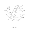
FIG. 8 is a perspective view diagrammatic illustration of a pilot nose cap of the pilot fuel injector tip of the fuel nozzle illustrated inFIG. 2 . - Illustrated in
FIG. 1 is an exemplary embodiment of acombustor 16 including acombustion zone 18 defined between and by annular radially outer andinner liners engine centerline 52. The outer andinner liners annular combustor casing 26 which extends circumferentially around outer andinner liners combustor 16 also includes anannular dome 34 mounted upstream of thecombustion zone 18 and attached to the outer andinner liners dome 34 defines anupstream end 36 of thecombustion zone 18 and a plurality of mixer assemblies 40 (only one is illustrated) are spaced circumferentially around thedome 34. Eachmixer assembly 40 includes amain mixer 104 mounted in thedome 34 and apilot mixer 102. - The
combustor 16 receives an annular stream of pressurized compressor discharge air 14 from a high pressurecompressor discharge outlet 69 at what is referred to as CDP air (compressor discharge pressure air). Afirst portion 23 of the compressor discharge air 14 flows into themixer assembly 40, where fuel is also injected to mix with the air and form a fuel-air mixture 65 that is provided to thecombustion zone 18 for combustion. Ignition of the fuel-air mixture 65 is accomplished by asuitable igniter 70, and the resultingcombustion gases 60 flow in an axial direction toward and into an annular, firststage turbine nozzle 72. The firststage turbine nozzle 72 is defined by an annular flow channel that includes a plurality of radially extending, circularly-spaced nozzle vanes 74 that turn the gases so that they flow angularly and impinge upon the first stage turbine blades (not shown) of a first turbine (not shown). - The arrows in
FIG. 1 illustrate the directions in which compressor discharge air flows withincombustor 16. Asecond portion 24 of the compressor discharge air 14 flows around theouter liner 20 and athird portion 25 of the compressor discharge air 14 flows around theinner liner 22. Afuel injector 10, further illustrated inFIG. 2 , includes a nozzle mount orflange 30 adapted to be fixed and sealed to thecombustor casing 26. Ahollow stem 32 of thefuel injector 10 is integral with or fixed to the flange 30 (such as by brazing or welding) and includes afuel nozzle assembly 12. Thehollow stem 32 supports thefuel nozzle assembly 12 and thepilot mixer 102. Avalve housing 37 at the top of thestem 32 contains valves illustrated and discussed in more detail in United States Patent Application No.20100263382 , referenced above. - Referring to
FIG. 2 , thefuel nozzle assembly 12 includes amain fuel nozzle 61 and anannular pilot inlet 54 to thepilot mixer 102 through which thefirst portion 23 of the compressor discharge air 14 flows. Thefuel nozzle assembly 12 further includes a dual orifice pilotfuel injector tip 57 substantially centered in theannular pilot inlet 54. The dual orifice pilotfuel injector tip 57 includes concentric primary and secondarypilot fuel nozzles pilot mixer 102 includes acenterline axis 120 about which the dual orifice pilotfuel injector tip 57, the primary and secondarypilot fuel nozzles annular pilot inlet 54 and themain fuel nozzle 61 are centered and circumscribed. - The
main fuel nozzle 61 is spaced radially outwardly of the primary and secondarypilot fuel nozzles pilot fuel nozzle 59 is radially located directly adjacent to and surrounds the primarypilot fuel nozzle 58. The primary and secondarypilot fuel nozzles main fuel nozzle 61 and themixer assembly 40 are used to deliver thefuel air mixture 65 to thecombustion zone 18. Themain fuel nozzle 61 includes a circular or annular array of radially outwardly openfuel injection orifices 63. A fuel nozzleouter casing 71 surrounds themain fuel nozzle 61 and includes cylindricalfuel spray holes 73 aligned with thefuel injection orifices 63. - A
pilot housing 99 includes acenterbody 103 and radially inwardly supports the pilotfuel injector tip 57 and radially outwardly supports themain fuel nozzle 61. Thecenterbody 103 is radially disposed between the pilotfuel injector tip 57 and themain fuel nozzle 61. Thecenterbody 103 surrounds thepilot mixer 102 and defines achamber 105 that is in flow communication with, and downstream from, thepilot mixer 102. Thepilot mixer 102 radially supports the dual orifice pilotfuel injector tip 57 at a radially inner diameter ID and thecenterbody 103 radially supports themain fuel nozzle 61 at a radially outer diameter OD with respect to theengine centerline 52. Themain fuel nozzle 61 is disposed within the main mixer 104 (illustrated inFIG. 1 ) of themixer assembly 40 and the dual orifice pilotfuel injector tip 57 is disposed within thepilot mixer 102. - The
pilot mixer 102 includes aninner pilot swirler 112 located radially outwardly of and adjacent to the dual orifice pilotfuel injector tip 57, anouter pilot swirler 114 located radially outwardly of theinner pilot swirler 112, and aswirler splitter 116 positioned therebetween. Theswirler splitter 116 extends downstream of the dual orifice pilotfuel injector tip 57 and aventuri 118 is formed in adownstream portion 115 of theswirler splitter 116. Theventuri 118 includes a convergingsection 117, a divergingsection 119, and athroat 121 therebetween. Thethroat 121 is located downstream of aprimary exit 98 of the primarypilot fuel nozzle 58. The inner andouter pilot swirlers centerline axis 120 of the dual orifice pilotfuel injector tip 57 and the mixingassembly 40. The inner andouter pilot swirlers vanes 44 for swirling air traveling therethrough. Fuel and air are provided topilot mixer 102 at all times during the engine operating cycle so that a primary combustion zone 122 (illustrated inFIG. 1 ) is produced within a central portion ofcombustion zone 18. - The primary and secondary
pilot fuel nozzles secondary exits main fuel nozzle 61 is operable to inject fuel in a generally radially outwardly direction through the circular array of radially outwardly open fuel injection orifices 63. The primarypilot fuel nozzle 58 includes a primaryfuel supply passage 158 which feeds fuel to the circularprimary exit 98 at a firstdownstream end 142 of the primarypilot fuel nozzle 58. The secondarypilot fuel nozzle 59 includes an annular secondaryfuel supply passage 159 which flows fuel to the annularsecondary exit 100 at a seconddownstream end 143 of the secondarypilot fuel nozzle 59. - Referring to
FIGS. 2 and5-7 , aprimary fuel swirler 136 adjacent thedownstream end 142 of the primaryfuel supply passage 158 is used to swirl the fuel flow exiting the circularprimary exit 98. The exemplaryprimary fuel swirler 136 illustrated herein is a cylindrical plug having downstream and circumferentially angled fuel injection holes 164 to pre-film a conicalprimary exit orifice 166 of the primarypilot fuel nozzle 58 with fuel which improves atomization of the fuel. The conicalprimary exit orifice 166 culminates at the circularprimary exit 98. Theprimary fuel swirler 136 swirls the fuel and centrifugal force of the swirling fuel forces the fuel against a primaryconical surface 168 of the conicalprimary exit orifice 166 thus pre-filming the fuel along the primaryconical surface 168. - Referring to
FIGS. 2 and5-7 , an annularsecondary fuel swirler 137 in the annular secondaryfuel supply passage 159 adjacent thedownstream end 143 of the secondarypilot fuel nozzle 59 is used to swirl the fuel flow exiting the annularsecondary exit 100. The exemplarysecondary fuel swirler 137, as illustrated herein, is anannular array 180 ofhelical spin slots 182 operable to pre-film a conicalsecondary exit orifice 167 of the secondarypilot fuel nozzle 59 with fuel which improves atomization of the fuel. Thehelical spin slots 182 are illustrated herein as having arectangular cross section 183 with respect to fuel flow direction through thehelical spin slots 182. The conicalsecondary exit orifice 167 culminates at the annularsecondary exit 100. Thesecondary fuel swirler 137 swirls the fuel and centrifugal force of the swirling fuel forces it against a secondaryconical surface 169 of the conicalsecondary exit orifice 167 thus pre-filming the fuel along the secondaryconical surface 169. - Concentric annular primary and secondary fuel films from the concentric primary and secondary
pilot fuel nozzles pilot mixer 102 which is at its maximum velocity in a plane in the vicinity of the annularsecondary exit 100. In order to reduce interaction between the primary and secondary fuel films ejected from the concentric primary and secondarypilot fuel nozzles primary exit 98 is located axially aft and downstream of the annularsecondary exit 100. This results in physically separating the primary and secondary fuel films after they are ejected from the concentric primary and secondarypilot fuel nozzles - This separation better positions the fuel films within a shear layer of inner
pilot swirler flow 138 from theinner pilot swirler 112 and improves fuel atomization and reduces intermittency in the overall spray quality over a wide-range of engine operating conditions. This also allows an accurate placement of fuel close to the shear layers to provide maximum flexibility which in turn plays a major role in emissions and engine operability over a range of engine operating conditions. Locating the circularprimary exit 98 axially aft and downstream of the annularsecondary exit 100 allows the pre-filming primaryconical surface 168 of the conicalprimary exit orifice 166 of the primarypilot fuel nozzle 58 and the secondaryconical surface 169 of the conicalsecondary exit orifice 167 of the secondarypilot fuel nozzle 59 to release fuel closest to the incoming shear layer and do so consistently for a variety of fueling modes and engine operating conditions. - Referring to
FIGS. 5 and6 , theinner pilot swirler 112 has a generally cylindrical inner pilotswirler flowpath section 222 followed by an annular inwardly taperingconical flowpath section 224 between theswirler splitter 116 and a radiallyouter wall 226 of the pilotfuel injector tip 57. Theconical flowpath section 224 surrounds the firstdownstream end 142 of the primarypilot fuel nozzle 58 including the circularprimary exit 98. Theconical flowpath section 224 also surrounds secondary the seconddownstream end 143 of the secondarypilot fuel nozzle 59 including the annularsecondary exit 100. - The inwardly tapering
conical flowpath section 224 is radially inwardly bounded by an inwardly taperingconical wall section 230 of the radiallyouter wall 226 in the convergingsection 117 of theventuri 118. Illustrated inFIG. 6 is aconical surface 232 in space defined by the inwardly taperingconical wall section 230. The circular primary and annularsecondary exits conical surface 232 in order to release fuel closest to the incoming shear layer and do so consistently for a variety of fueling modes and engine operating conditions. - A cross over
arm 56, illustrated inFIGS. 2 ,3 , and4 , extends radially across theannular pilot inlet 54 from themain fuel nozzle 61 to the pilotfuel injector tip 57. The cross overarm 56 includes an aerodynamically drag reducing cross over arm fairing 62, or tube, surrounding primary and secondaryfuel transfer tubes annular pilot inlet 54 to the primary and secondaryfuel supply passages fuel injector tip 57. The cross over arm fairing 62 includes rounded leading and trailingedges second sides middle section 76 extending between the rounded leading and trailingedges edges edge 80 is representative of arounded forebody 46 and the rectangularmiddle section 76 with the spaced apart flat first andsecond sides straight afterbody 48. - Referring to
FIGS. 1-5 and8 , an aerodynamically drag reducingpilot nose cap 53 also referred to as a bullet nose or rounded nose is located at anupstream end 55 of the pilotfuel injector tip 57. Thepilot nose cap 53 includes a rounded or more specifically a generally oval shapednose base 77 and a substantially roundeddome 78 extending forwardly or upstream from thenose base 77. Acylindrical nose afterbody 92 or more specifically a substantially ovalcylindrical nose afterbody 92 extends axially aft or downstream from thenose base 77. The nose afterbody 92 is centered about and parallel to apilot nose centerline 111 perpendicular or normal to thenose base 77. Therounded dome 78 is representative of arounded forebody 46 and thenose afterbody 92 is representative of astraight afterbody 48. - The
pilot nose centerline 111 is illustrated herein as collinear with thecenterline axis 120 about which the pilotfuel injector tip 57 is centered and circumscribed. Alternatively, thepilot nose centerline 111 may be angled and/or slightly offset with respect to thecenterline axis 120 to more evenly distribute and alignpilot airflow 101 flowing into thepilot mixer 102 and its inner andouter pilot swirlers pilot nose centerline 111 may be angled up to about 10 degrees with respect to thecenterline axis 120. - As illustrated herein, the
pilot nose cap 53 includes a generally oval shapednose base 77 and a substantially roundeddome 78 extending forwardly or upstream from thenose base 77. Thedome 78 is illustrated herein as a generally oval rounded dome having a slight blunted orflat top 86. Thenose base 77 has a generallyoval perimeter 88 with circular first andsecond end segments curved side segments 109. The circular first andsecond end segments curved side segments 109 are illustrated herein as being generally mirror image arcs having second radii R2 substantially greater than the first radii R1. The exemplarycurved side segments 109 illustrated herein also include straightmiddle sections 113 centered in thecurved side segments 109. A centerconical section 90 of thedome 78 extends forwardly or upstream from the straightmiddle sections 113 of thecurved side segments 109 and illustrated herein as having a rectangularflat top 86. - The nose afterbody 92 is illustrated as having oval cross sectional shape matching the
oval perimeter 88 of thenose base 77. The nose afterbody 92 extends aft or downstream from and at substantially 90 degrees from or normal to thenose base 77. The nose afterbody 92 includes spaced apart rounded first and second ends 146, 148 corresponding to the circular first andsecond end segments sides 409 corresponding to thecurved side segments 109 of theoval perimeter 88. The exemplary embodiment of thenose afterbody 92 illustrated herein also includes a rectangularmiddle section 149 disposed between the rounded first and second ends 146, 148. The rectangularmiddle section 149 includes spaced apartflat sides 152 corresponding to the straightmiddle sections 113 of theoval perimeter 88. The curved andflat sides curved side segments 109 and straightmiddle sections 113 respectively of theoval perimeter 88. - The cross over arm fairing 62 and the
pilot nose cap 53 are both example of fuel injector fairings designed to minimize flow obstruction, avoid asymmetric flow, and maximize thepilot airflow 101 through thepilot mixer 102 and its inner andouter pilot swirlers pilot airflow 101. The cross over arm fairing 62 and thepilot nose cap 53 have roundedforebodies 46 followed bystraight afterbodies 48. The exemplary embodiment of thefuel nozzle assembly 12 illustrated herein depicts thestraight afterbodies 48 as being parallel to thepilot nose centerline 111. - Referring to
FIGS. 2 and5 , an axially or downstream extendinginjector cooling flowpath 190 is disposed in thepilot housing 99 and radially between a fuel nozzleinner casing 79 and thecenterbody 103. Themain fuel nozzle 61 is radially disposed outwardly of and supported at least in part by the fuel nozzleinner casing 79. Theinjector cooling flowpath 190 extends axially downstream or aft from theannular pilot inlet 54 to an aftannular plenum 192 at anaft end 194 of theinjector cooling flowpath 190. The aftannular plenum 192 includes an annular groove, slot, orpocket 195 in a radially outwardly extendingaft flange 196 of the fuel nozzleinner casing 79 and is radially inwardly bounded by thecenterbody 103. Coolingholes 198 through an axially aftannular wall 200 of theaft flange 196 direct cooling air from the aftannular plenum 192 onto a radially outwardly extending aftheat shield flange 197 on anaft end 202 of thecenterbody 103. Anannular heat shield 204 faces thecombustion zone 18 and is mounted on theheat shield flange 197. - An annular
cooling flowpath inlet 206 to theinjector cooling flowpath 190 is radially inwardly bounded by thecenterbody 103. An upstreamforward end 208 of thecenterbody 103 is radially disposed between theouter pilot swirler 114 and the centerbody 103 and operates as a flow splitter between theouter pilot swirler 114 and the annularcooling flowpath inlet 206 to theinjector cooling flowpath 190. Theforward end 208 of thecenterbody 103 is an annular wall section including an annular chamfered leadingedge 210 having a radially inwardly facing conical chamferedsurface 212. The chamfered leadingedge 210 operates as a dirt deflector that diverts dirt in thepilot airflow 101 away from the coolingflowpath inlet 206. - Various aspects and embodiments of the invention are indicated in the following numbered clauses:
- 1. A pilot fuel injector tip comprising:
- substantially concentric primary and secondary pilot fuel nozzles centered about a centerline axis of the pilot fuel injector tip,
- the primary and secondary pilot fuel nozzles having circular primary and annular secondary exits respectively, and
- the circular primary exit located axially aft and downstream of the annular secondary exit.
- 2. A pilot fuel injector tip as claimed in Clause 1, further comprising:
- an annular secondary fuel supply passage operable for flowing fuel to the annular secondary exit in the secondary pilot fuel nozzle,
- an annular secondary fuel swirler in the secondary fuel supply passage, and
- the secondary fuel swirler including an annular array of helical spin slots.
- 3. A pilot fuel injector tip as claimed in Clause 2, further comprising the helical spin slots having rectangular cross sections.
- 4. A gas turbine engine fuel nozzle assembly comprising:
- a pilot fuel injector tip substantially centered about a centerline axis in an annular pilot inlet to a pilot mixer,
- substantially concentric primary and secondary pilot fuel nozzles in the pilot fuel injector tip,
- the primary and secondary pilot fuel nozzles having circular primary and annular secondary exits respectively, and
- the circular primary exit located axially aft and downstream of the annular secondary exit.
- 5. A fuel nozzle assembly as claimed in Clause 4, further comprising:
- an annular secondary fuel supply passage operable for flowing fuel to the annular secondary exit in the secondary pilot fuel nozzle,
- an annular secondary fuel swirler in the secondary fuel supply passage, and
- the secondary fuel swirler including an annular array of helical spin slots.
- 6. A fuel nozzle assembly as claimed in Clause 5, further comprising the helical spin slots having rectangular cross sections.
- 7. A fuel nozzle assembly as claimed in Clause 4, further comprising:
- an annular inwardly tapering conical flowpath section of a pilot swirler flowpath section,
- a first downstream end of the primary pilot fuel nozzle including the circular primary exit,
- a second downstream end of the secondary pilot fuel nozzle including the annular secondary exit,
- the annular inwardly tapering conical flowpath section surrounding the first and second downstream ends,
- an inwardly tapering conical wall section radially inwardly bounding the annular inwardly tapering conical flowpath section and defining a conical surface, and
- the circular primary and annular secondary exits located at or axially forward or upstream of the conical surface.
- 8. A fuel nozzle assembly as claimed in Clause 7, further comprising:
- an annular secondary fuel supply passage operable for flowing fuel to the annular secondary exit in the secondary pilot fuel nozzle,
- an annular secondary fuel swirler in the secondary fuel supply passage, and
- the secondary fuel swirler including an annular array of helical spin slots.
- 9. A fuel nozzle assembly as claimed in Clause 8, further comprising the helical spin slots having rectangular cross sections.
- 10. A fuel injector as claimed in Clause 4, further comprising:
- an inner pilot swirler located radially outwardly of and adjacent to the dual orifice pilot fuel injector tip,
- an outer pilot swirler located radially outwardly of the inner swirler,
- a splitter radially positioned between the first and second pilot swirlers,
- the inner pilot swirler including a generally cylindrical inner pilot swirler flowpath section upstream and axially forward of an annular inwardly tapering conical flowpath section between the splitter and a radially outer wall of the pilot fuel injector tip,
- an inwardly tapering conical wall section of the radially outer wall radially inwardly bounding the inwardly tapering conical flowpath section,
- a conical surface defined by the inwardly tapering conical wall section, and
- the circular primary and annular secondary exits located at or axially forward or upstream of the conical surface.
- 11. A fuel nozzle assembly as claimed in
Clause 10, further comprising:- an annular secondary fuel supply passage operable for flowing fuel to the annular secondary exit in the secondary pilot fuel nozzle,
- an annular secondary fuel swirler in the secondary fuel supply passage, and
- the secondary fuel swirler including an annular array of helical spin slots.
- 12. A fuel nozzle assembly as claimed in Clause 11, further comprising the helical spin slots having rectangular cross sections.
- 13. A fuel nozzle assembly as claimed in Clause 4, further comprising:
- an inner pilot swirler located radially outwardly of and adjacent to the dual orifice pilot fuel injector tip,
- an outer pilot swirler located radially outwardly of the inner swirler,
- an axially aft or downstream extending injector cooling flowpath disposed radially outwardly of and surrounding the second pilot swirler,
- an annular wall section radially disposed between the outer pilot swirler and an annular cooling flowpath inlet to the injector cooling flowpath,
- an annular chamfered leading edge of the annular wall section, and
- a radially inwardly facing conical chamfered surface of the chamfered leading edge.
- 14. A fuel injector as claimed in Clause 13, further comprising:
- a splitter radially positioned between the first and second pilot swirlers,
- the inner pilot swirler including a generally cylindrical inner pilot swirler flowpath section upstream and axially forward of an annular inwardly tapering conical flowpath section between the splitter and a radially outer wall of the pilot fuel injector tip,
- an inwardly tapering conical wall section of the radially outer wall radially inwardly bounding the inwardly tapering conical flowpath section,
- a conical surface defined by the inwardly tapering conical wall section, and
- the circular primary and annular secondary exits located at or axially forward or upstream of the conical surface.
- 15. A fuel nozzle assembly as claimed in Clause 14, further comprising:
- an annular secondary fuel supply passage operable for flowing fuel to the annular secondary exit in the secondary pilot fuel nozzle,
- an annular secondary fuel swirler in the secondary fuel supply passage, and
- the secondary fuel swirler including an annular array of helical spin slots.
- 16. A fuel nozzle assembly as claimed in Clause 4, further comprising:
- a pilot housing including a centerbody radially surrounding the pilot mixer,
- an axially or downstream extending injector cooling flowpath disposed in the pilot housing and radially between a fuel nozzle inner casing and the centerbody,
- an upstream forward end of the centerbody including an annular chamfered leading edge of the forward end, and
- a radially inwardly facing conical chamfered surface of the chamfered leading edge.
- 17. A fuel nozzle assembly as claimed in
Clause 16, further comprising:- a first pilot swirler located radially outwardly of and adjacent to the dual orifice pilot fuel injector tip,
- a second pilot swirler located radially outwardly of the first swirler, and
- a splitter radially positioned between the first and second pilot swirlers.
- 18. A fuel nozzle assembly as claimed in Clause 17, further comprising a main fuel nozzle located radially outwardly of the primary and secondary pilot fuel nozzles and supported at least in part by the fuel nozzle inner casing.
- 19. A fuel nozzle assembly as claimed in
Clause 18, further comprising:- an annular secondary fuel supply passage operable for flowing fuel to the annular secondary exit in the secondary pilot fuel nozzle,
- an annular secondary fuel swirler in the secondary fuel supply passage, and
- the secondary fuel swirler including an annular array of helical spin slots.
- 20. A fuel nozzle assembly as claimed in Clause 19, further comprising the helical spin slots having rectangular cross sections.
Claims (10)
- A pilot fuel injector tip (57) comprising:substantially concentric primary and secondary pilot fuel nozzles (58, 59) centered about a centerline axis (120) of the pilot fuel injector tip (57),the primary and secondary pilot fuel nozzles (58, 59) having circular primary and annular secondary exits (98, 100) respectively, andthe circular primary exit (98) located axially aft and downstream of the annular secondary exit (100).
- A pilot fuel injector tip (57) as claimed in Claim 1, further comprising:an annular secondary fuel supply passage (159) operable for flowing fuel to the annular secondary exit (100) in the secondary pilot fuel nozzle (59),an annular secondary fuel swirler (137) in the secondary fuel supply passage (159),
andthe secondary fuel swirler (137) including an annular array (180) of helical spin slots (182). - A pilot fuel injector tip (57) as claimed in Claim 2, further comprising the helical spin slots (182) having rectangular cross sections (183).
- A gas turbine engine fuel nozzle assembly (12) comprising:the pilot fuel injector tip (57) according to claim 1, the pilot fuel injector tip (57) substantially centered about a centerline axis (120) in an annular pilot inlet (54) to a pilot mixer (102).
- A fuel nozzle assembly (12) as claimed in Claim 4, further comprising:an annular secondary fuel supply passage (159) operable for flowing fuel to the annular secondary exit (100) in the secondary pilot fuel nozzle (59),an annular secondary fuel swirler (137) in the secondary fuel supply passage (159),
andthe secondary fuel swirler (137) including an annular array (180) of helical spin slots (182). - A fuel nozzle assembly (12) as claimed in Claim 5, further comprising the helical spin slots (182) having rectangular cross sections (183).
- A fuel nozzle assembly (12) as claimed in Claim 4, further comprising:an annular inwardly tapering conical flowpath section (224) of a pilot swirler flowpath section (222),a first downstream end (142) of the primary pilot fuel nozzle (58) including the circular primary exit (98),a second downstream end (143) of the secondary pilot fuel nozzle (59) including the annular secondary exit (100),the annular inwardly tapering conical flowpath section (224) surrounding the first and second downstream ends (142, 143),an inwardly tapering conical wall section (230) radially inwardly bounding the annular inwardly tapering conical flowpath section (224) and defining a conical surface (232), andthe circular primary and annular secondary exits (98, 100) located at or axially forward or upstream of the conical surface (232).
- A fuel nozzle assembly (12) as claimed in Claim 7, further comprising:an annular secondary fuel supply passage (159) operable for flowing fuel to the annular secondary exit (100) in the secondary pilot fuel nozzle (59),an annular secondary fuel swirler (137) in the secondary fuel supply passage (159),
andthe secondary fuel swirler (137) including an annular array (180) of helical spin slots (182). - A fuel nozzle assembly (12) as claimed in Claim 8, further comprising the helical spin slots (182) having rectangular cross sections (183).
- A fuel injector (10) as claimed in Claim 4, further comprising:an inner pilot swirler (112) located radially outwardly of and adjacent to the pilot fuel injector tip (57),an outer pilot swirler (114) located radially outwardly of the inner swirler (112),a splitter (116) radially positioned between the first and second pilot swirlers (112, 114),the inner pilot swirler (112) including a generally cylindrical inner pilot swirler flowpath section (222) upstream and axially forward of an annular inwardly tapering conical flowpath section (224) between the splitter (116) and a radially outer wall (226) of the pilot fuel injector tip (57),an inwardly tapering conical wall section (230) of the radially outer wall (226) radially inwardly bounding the inwardly tapering conical flowpath section (224),a conical surface (232) defined by the inwardly tapering conical wall section (230),
andthe circular primary and annular secondary exits (98, 100) located at or axially forward or upstream of the conical surface (232).
Applications Claiming Priority (1)
| Application Number | Priority Date | Filing Date | Title |
|---|---|---|---|
| US12/971,597 US8726668B2 (en) | 2010-12-17 | 2010-12-17 | Fuel atomization dual orifice fuel nozzle |
Publications (2)
| Publication Number | Publication Date |
|---|---|
| EP2466207A2 true EP2466207A2 (en) | 2012-06-20 |
| EP2466207A3 EP2466207A3 (en) | 2017-11-15 |
Family
ID=45098931
Family Applications (1)
| Application Number | Title | Priority Date | Filing Date |
|---|---|---|---|
| EP11191658.1A Withdrawn EP2466207A3 (en) | 2010-12-17 | 2011-12-02 | Fuel atomization dual orifice fuel nozzle |
Country Status (4)
| Country | Link |
|---|---|
| US (1) | US8726668B2 (en) |
| EP (1) | EP2466207A3 (en) |
| JP (1) | JP6035021B2 (en) |
| CA (1) | CA2760046A1 (en) |
Cited By (5)
| Publication number | Priority date | Publication date | Assignee | Title |
|---|---|---|---|---|
| CN104781610A (en) * | 2012-11-15 | 2015-07-15 | 通用电气公司 | Fuel nozzle heat shield |
| CN108980891A (en) * | 2018-04-27 | 2018-12-11 | 北京航空航天大学 | A kind of center classification low emission combustor head with pneumatic water conservancy diversion and anti-backfire structure |
| WO2019241108A1 (en) * | 2018-06-11 | 2019-12-19 | Woodward, Inc. | Pre-swirl pressure atomizing tip |
| CN111197764A (en) * | 2018-11-20 | 2020-05-26 | 通用电气公司 | Annular concentric fuel nozzle assembly |
| EP4056818A1 (en) * | 2021-02-26 | 2022-09-14 | Marelli Europe S.p.A. | Heating device for an exhaust system of an internal combustion engine |
Families Citing this family (48)
| Publication number | Priority date | Publication date | Assignee | Title |
|---|---|---|---|---|
| US20130199191A1 (en) * | 2011-06-10 | 2013-08-08 | Matthew D. Tyler | Fuel injector with increased feed area |
| US9400104B2 (en) * | 2012-09-28 | 2016-07-26 | United Technologies Corporation | Flow modifier for combustor fuel nozzle tip |
| GB201222304D0 (en) | 2012-12-12 | 2013-01-23 | Rolls Royce Plc | A fuel injector and a gas turbine engine combustion chamber |
| US9592480B2 (en) * | 2013-05-13 | 2017-03-14 | Solar Turbines Incorporated | Inner premix tube air wipe |
| US10794596B2 (en) * | 2013-08-30 | 2020-10-06 | Raytheon Technologies Corporation | Dual fuel nozzle with liquid filming atomization for a gas turbine engine |
| EP3039343B8 (en) * | 2013-08-30 | 2021-03-31 | Raytheon Technologies Corporation | Dual fuel nozzle with swirling axial gas injection for a gas turbine engine and related method |
| WO2015122952A2 (en) | 2013-11-27 | 2015-08-20 | General Electric Company | Fuel nozzle with fluid lock and purge apparatus |
| CN105829800B (en) | 2013-12-23 | 2019-04-26 | 通用电气公司 | The fuel nozzle configuration of fuel injection for air assisted |
| JP6695801B2 (en) * | 2013-12-23 | 2020-05-20 | ゼネラル・エレクトリック・カンパニイ | Fuel nozzle with flexible support structure |
| JP6429994B2 (en) | 2014-08-14 | 2018-11-28 | シーメンス アクチエンゲゼルシヤフトSiemens Aktiengesellschaft | Multifunctional fuel nozzle with heat shield |
| US9958152B2 (en) | 2014-08-14 | 2018-05-01 | Siemens Aktiengesellschaft | Multi-functional fuel nozzle with an atomizer array |
| EP3180565B1 (en) | 2014-08-14 | 2019-04-17 | Siemens Aktiengesellschaft | Multi-functional fuel nozzle with a dual-orifice atomizer |
| US10012387B2 (en) | 2014-12-05 | 2018-07-03 | General Electric Company | Fuel supply system for a gas turbine engine |
| US10591164B2 (en) | 2015-03-12 | 2020-03-17 | General Electric Company | Fuel nozzle for a gas turbine engine |
| US10385809B2 (en) | 2015-03-31 | 2019-08-20 | Delavan Inc. | Fuel nozzles |
| KR101657535B1 (en) * | 2015-05-21 | 2016-09-19 | 두산중공업 주식회사 | Fuel supply nozzle to minimize burning damage. |
| US10047959B2 (en) | 2015-12-29 | 2018-08-14 | Pratt & Whitney Canada Corp. | Fuel injector for fuel spray nozzle |
| US10584876B2 (en) | 2016-03-25 | 2020-03-10 | General Electric Company | Micro-channel cooling of integrated combustor nozzle of a segmented annular combustion system |
| US10584880B2 (en) | 2016-03-25 | 2020-03-10 | General Electric Company | Mounting of integrated combustor nozzles in a segmented annular combustion system |
| US10520194B2 (en) | 2016-03-25 | 2019-12-31 | General Electric Company | Radially stacked fuel injection module for a segmented annular combustion system |
| US10563869B2 (en) | 2016-03-25 | 2020-02-18 | General Electric Company | Operation and turndown of a segmented annular combustion system |
| US11428413B2 (en) | 2016-03-25 | 2022-08-30 | General Electric Company | Fuel injection module for segmented annular combustion system |
| US10605459B2 (en) | 2016-03-25 | 2020-03-31 | General Electric Company | Integrated combustor nozzle for a segmented annular combustion system |
| US10724441B2 (en) | 2016-03-25 | 2020-07-28 | General Electric Company | Segmented annular combustion system |
| US10641491B2 (en) | 2016-03-25 | 2020-05-05 | General Electric Company | Cooling of integrated combustor nozzle of segmented annular combustion system |
| US10830442B2 (en) | 2016-03-25 | 2020-11-10 | General Electric Company | Segmented annular combustion system with dual fuel capability |
| US10690350B2 (en) | 2016-11-28 | 2020-06-23 | General Electric Company | Combustor with axially staged fuel injection |
| US11156362B2 (en) | 2016-11-28 | 2021-10-26 | General Electric Company | Combustor with axially staged fuel injection |
| US11149952B2 (en) * | 2016-12-07 | 2021-10-19 | Raytheon Technologies Corporation | Main mixer in an axial staged combustor for a gas turbine engine |
| US10837640B2 (en) | 2017-03-06 | 2020-11-17 | General Electric Company | Combustion section of a gas turbine engine |
| US10920673B2 (en) * | 2017-03-16 | 2021-02-16 | General Electric Company | Gas turbine with extraction-air conditioner |
| US10760793B2 (en) | 2017-07-21 | 2020-09-01 | General Electric Company | Jet in cross flow fuel nozzle for a gas turbine engine |
| US10954859B2 (en) | 2017-07-25 | 2021-03-23 | Raytheon Technologies Corporation | Low emissions combustor assembly for gas turbine engine |
| US10808934B2 (en) * | 2018-01-09 | 2020-10-20 | General Electric Company | Jet swirl air blast fuel injector for gas turbine engine |
| CN111050924B (en) * | 2018-04-02 | 2021-11-02 | 奥特德斯德哥尔摩股份有限公司 | Water-saving nozzle |
| US11112117B2 (en) | 2018-07-17 | 2021-09-07 | General Electric Company | Fuel nozzle cooling structure |
| FR3091333B1 (en) * | 2018-12-27 | 2021-05-14 | Safran Aircraft Engines | INJECTOR NOSE FOR TURBOMACHINE INCLUDING A PRIMARY FUEL CIRCUIT ARRANGED AROUND A SECONDARY FUEL CIRCUIT |
| US11253823B2 (en) | 2019-03-29 | 2022-02-22 | Delavan Inc. | Mixing nozzles |
| US11371702B2 (en) | 2020-08-31 | 2022-06-28 | General Electric Company | Impingement panel for a turbomachine |
| US11460191B2 (en) | 2020-08-31 | 2022-10-04 | General Electric Company | Cooling insert for a turbomachine |
| US11614233B2 (en) | 2020-08-31 | 2023-03-28 | General Electric Company | Impingement panel support structure and method of manufacture |
| US11255545B1 (en) | 2020-10-26 | 2022-02-22 | General Electric Company | Integrated combustion nozzle having a unified head end |
| GB202019219D0 (en) | 2020-12-07 | 2021-01-20 | Rolls Royce Plc | Lean burn combustor |
| GB202019222D0 (en) * | 2020-12-07 | 2021-01-20 | Rolls Royce Plc | Lean burn combustor |
| US11466859B2 (en) * | 2020-12-18 | 2022-10-11 | Pratt & Whitney Canada Corp. | Gap filler for a fuel system gallery |
| CN113048513B (en) * | 2021-04-14 | 2022-07-01 | 西北工业大学 | Multistage oil spout hole center cone integration afterburner |
| CN113606610B (en) * | 2021-07-27 | 2022-10-21 | 南京航空航天大学 | Pneumatic auxiliary atomization direct injection type nozzle applied to afterburner |
| US11767766B1 (en) | 2022-07-29 | 2023-09-26 | General Electric Company | Turbomachine airfoil having impingement cooling passages |
Citations (11)
| Publication number | Priority date | Publication date | Assignee | Title |
|---|---|---|---|---|
| US6354072B1 (en) | 1999-12-10 | 2002-03-12 | General Electric Company | Methods and apparatus for decreasing combustor emissions |
| US6363726B1 (en) | 2000-09-29 | 2002-04-02 | General Electric Company | Mixer having multiple swirlers |
| US6367262B1 (en) | 2000-09-29 | 2002-04-09 | General Electric Company | Multiple annular swirler |
| US6381964B1 (en) | 2000-09-29 | 2002-05-07 | General Electric Company | Multiple annular combustion chamber swirler having atomizing pilot |
| US6389815B1 (en) | 2000-09-08 | 2002-05-21 | General Electric Company | Fuel nozzle assembly for reduced exhaust emissions |
| US6418726B1 (en) | 2001-05-31 | 2002-07-16 | General Electric Company | Method and apparatus for controlling combustor emissions |
| US6453660B1 (en) | 2001-01-18 | 2002-09-24 | General Electric Company | Combustor mixer having plasma generating nozzle |
| US6484489B1 (en) | 2001-05-31 | 2002-11-26 | General Electric Company | Method and apparatus for mixing fuel to decrease combustor emissions |
| US6865889B2 (en) | 2002-02-01 | 2005-03-15 | General Electric Company | Method and apparatus to decrease combustor emissions |
| US7762073B2 (en) | 2006-03-01 | 2010-07-27 | General Electric Company | Pilot mixer for mixer assembly of a gas turbine engine combustor having a primary fuel injector and a plurality of secondary fuel injection ports |
| US20100263382A1 (en) | 2009-04-16 | 2010-10-21 | Alfred Albert Mancini | Dual orifice pilot fuel injector |
Family Cites Families (23)
| Publication number | Priority date | Publication date | Assignee | Title |
|---|---|---|---|---|
| US2884758A (en) * | 1956-09-10 | 1959-05-05 | Bbc Brown Boveri & Cie | Regulating device for burner operating with simultaneous combustion of gaseous and liquid fuel |
| US3013732A (en) * | 1959-09-01 | 1961-12-19 | Parker Hannifin Corp | Fuel injection nozzle |
| US4265615A (en) * | 1978-12-11 | 1981-05-05 | United Technologies Corporation | Fuel injection system for low emission burners |
| US5144804A (en) * | 1989-07-07 | 1992-09-08 | Fuel Systems Textron Inc. | Small airblast fuel nozzle with high efficiency inner air swirler |
| FR2817017B1 (en) * | 2000-11-21 | 2003-03-07 | Snecma Moteurs | COMPLETE COOLING OF THE TAKE-OFF INJECTORS OF A TWO-HEAD COMBUSTION CHAMBER |
| US6718770B2 (en) | 2002-06-04 | 2004-04-13 | General Electric Company | Fuel injector laminated fuel strip |
| US6898926B2 (en) | 2003-01-31 | 2005-05-31 | General Electric Company | Cooled purging fuel injectors |
| WO2005085709A1 (en) * | 2004-03-03 | 2005-09-15 | Mitsubishi Heavy Industries, Ltd. | Combustor |
| US7036302B2 (en) | 2004-03-15 | 2006-05-02 | General Electric Company | Controlled pressure fuel nozzle system |
| US6955040B1 (en) | 2004-03-31 | 2005-10-18 | General Electric Company | Controlled pressure fuel nozzle injector |
| US7779636B2 (en) | 2005-05-04 | 2010-08-24 | Delavan Inc | Lean direct injection atomizer for gas turbine engines |
| US20070028618A1 (en) * | 2005-07-25 | 2007-02-08 | General Electric Company | Mixer assembly for combustor of a gas turbine engine having a main mixer with improved fuel penetration |
| GB0516208D0 (en) | 2005-08-05 | 2005-09-14 | Rolls Royce Plc | Fuel injector |
| US7788927B2 (en) | 2005-11-30 | 2010-09-07 | General Electric Company | Turbine engine fuel nozzles and methods of assembling the same |
| US7878000B2 (en) | 2005-12-20 | 2011-02-01 | General Electric Company | Pilot fuel injector for mixer assembly of a high pressure gas turbine engine |
| GB0625016D0 (en) | 2006-12-15 | 2007-01-24 | Rolls Royce Plc | Fuel injector |
| US20090255120A1 (en) * | 2008-04-11 | 2009-10-15 | General Electric Company | Method of assembling a fuel nozzle |
| US8806871B2 (en) * | 2008-04-11 | 2014-08-19 | General Electric Company | Fuel nozzle |
| US8061142B2 (en) * | 2008-04-11 | 2011-11-22 | General Electric Company | Mixer for a combustor |
| US8517288B2 (en) * | 2009-01-20 | 2013-08-27 | Hosco Fittings LLC | Low shear swivel fitting |
| JP4733195B2 (en) * | 2009-04-27 | 2011-07-27 | 川崎重工業株式会社 | Fuel spray system for gas turbine engine |
| US20120151928A1 (en) | 2010-12-17 | 2012-06-21 | Nayan Vinodbhai Patel | Cooling flowpath dirt deflector in fuel nozzle |
| US8387391B2 (en) * | 2010-12-17 | 2013-03-05 | General Electric Company | Aerodynamically enhanced fuel nozzle |
-
2010
- 2010-12-17 US US12/971,597 patent/US8726668B2/en active Active
-
2011
- 2011-12-01 CA CA2760046A patent/CA2760046A1/en not_active Abandoned
- 2011-12-02 EP EP11191658.1A patent/EP2466207A3/en not_active Withdrawn
- 2011-12-14 JP JP2011272888A patent/JP6035021B2/en not_active Expired - Fee Related
Patent Citations (11)
| Publication number | Priority date | Publication date | Assignee | Title |
|---|---|---|---|---|
| US6354072B1 (en) | 1999-12-10 | 2002-03-12 | General Electric Company | Methods and apparatus for decreasing combustor emissions |
| US6389815B1 (en) | 2000-09-08 | 2002-05-21 | General Electric Company | Fuel nozzle assembly for reduced exhaust emissions |
| US6363726B1 (en) | 2000-09-29 | 2002-04-02 | General Electric Company | Mixer having multiple swirlers |
| US6367262B1 (en) | 2000-09-29 | 2002-04-09 | General Electric Company | Multiple annular swirler |
| US6381964B1 (en) | 2000-09-29 | 2002-05-07 | General Electric Company | Multiple annular combustion chamber swirler having atomizing pilot |
| US6453660B1 (en) | 2001-01-18 | 2002-09-24 | General Electric Company | Combustor mixer having plasma generating nozzle |
| US6418726B1 (en) | 2001-05-31 | 2002-07-16 | General Electric Company | Method and apparatus for controlling combustor emissions |
| US6484489B1 (en) | 2001-05-31 | 2002-11-26 | General Electric Company | Method and apparatus for mixing fuel to decrease combustor emissions |
| US6865889B2 (en) | 2002-02-01 | 2005-03-15 | General Electric Company | Method and apparatus to decrease combustor emissions |
| US7762073B2 (en) | 2006-03-01 | 2010-07-27 | General Electric Company | Pilot mixer for mixer assembly of a gas turbine engine combustor having a primary fuel injector and a plurality of secondary fuel injection ports |
| US20100263382A1 (en) | 2009-04-16 | 2010-10-21 | Alfred Albert Mancini | Dual orifice pilot fuel injector |
Cited By (10)
| Publication number | Priority date | Publication date | Assignee | Title |
|---|---|---|---|---|
| CN104781610A (en) * | 2012-11-15 | 2015-07-15 | 通用电气公司 | Fuel nozzle heat shield |
| CN104781610B (en) * | 2012-11-15 | 2017-03-08 | 通用电气公司 | fuel nozzle heat shield |
| US10072845B2 (en) | 2012-11-15 | 2018-09-11 | General Electric Company | Fuel nozzle heat shield |
| US10969104B2 (en) | 2012-11-15 | 2021-04-06 | General Electric Company | Fuel nozzle heat shield |
| CN108980891A (en) * | 2018-04-27 | 2018-12-11 | 北京航空航天大学 | A kind of center classification low emission combustor head with pneumatic water conservancy diversion and anti-backfire structure |
| CN108980891B (en) * | 2018-04-27 | 2020-08-21 | 北京航空航天大学 | Center-graded low-emission combustion chamber head with pneumatic flow guide and anti-backfire structure |
| WO2019241108A1 (en) * | 2018-06-11 | 2019-12-19 | Woodward, Inc. | Pre-swirl pressure atomizing tip |
| US11149950B2 (en) | 2018-06-11 | 2021-10-19 | Woodward, Inc. | Pre-swirl pressure atomizing tip |
| CN111197764A (en) * | 2018-11-20 | 2020-05-26 | 通用电气公司 | Annular concentric fuel nozzle assembly |
| EP4056818A1 (en) * | 2021-02-26 | 2022-09-14 | Marelli Europe S.p.A. | Heating device for an exhaust system of an internal combustion engine |
Also Published As
| Publication number | Publication date |
|---|---|
| EP2466207A3 (en) | 2017-11-15 |
| JP6035021B2 (en) | 2016-11-30 |
| US8726668B2 (en) | 2014-05-20 |
| US20120151930A1 (en) | 2012-06-21 |
| JP2012132671A (en) | 2012-07-12 |
| CA2760046A1 (en) | 2012-06-17 |
Similar Documents
| Publication | Publication Date | Title |
|---|---|---|
| US8726668B2 (en) | Fuel atomization dual orifice fuel nozzle | |
| US8387391B2 (en) | Aerodynamically enhanced fuel nozzle | |
| EP2466206A2 (en) | Cooling flowpath dirt deflector in fuel nozzle | |
| US9562690B2 (en) | Swirler, fuel and air assembly and combustor | |
| US11421884B2 (en) | System for aerodynamically enhanced premixer for reduced emissions | |
| US7762073B2 (en) | Pilot mixer for mixer assembly of a gas turbine engine combustor having a primary fuel injector and a plurality of secondary fuel injection ports | |
| US7878000B2 (en) | Pilot fuel injector for mixer assembly of a high pressure gas turbine engine | |
| US7757491B2 (en) | Fuel nozzle for a gas turbine engine and method for fabricating the same | |
| US7908863B2 (en) | Fuel nozzle for a gas turbine engine and method for fabricating the same | |
| US20100263382A1 (en) | Dual orifice pilot fuel injector | |
| US11713881B2 (en) | Premixer for a combustor | |
| GB2451517A (en) | Pilot mixer for mixer assembly of a gas turbine engine combustor having a primary fuel injector and a plurality of secondary fuel injection ports | |
| CA2597846A1 (en) | Pilot fuel injector for mixer assembly of a high pressure gas turbine engine | |
| US11754288B2 (en) | Combustor mixing assembly | |
| CA2596789C (en) | Pilot mixer for mixer assembly of a gas turbine engine combustor having a primary fuel injector and a plurality of secondary fuel injection ports |
Legal Events
| Date | Code | Title | Description |
|---|---|---|---|
| PUAI | Public reference made under article 153(3) epc to a published international application that has entered the european phase |
Free format text: ORIGINAL CODE: 0009012 |
|
| AK | Designated contracting states |
Kind code of ref document: A2 Designated state(s): AL AT BE BG CH CY CZ DE DK EE ES FI FR GB GR HR HU IE IS IT LI LT LU LV MC MK MT NL NO PL PT RO RS SE SI SK SM TR |
|
| AX | Request for extension of the european patent |
Extension state: BA ME |
|
| PUAL | Search report despatched |
Free format text: ORIGINAL CODE: 0009013 |
|
| AK | Designated contracting states |
Kind code of ref document: A3 Designated state(s): AL AT BE BG CH CY CZ DE DK EE ES FI FR GB GR HR HU IE IS IT LI LT LU LV MC MK MT NL NO PL PT RO RS SE SI SK SM TR |
|
| AX | Request for extension of the european patent |
Extension state: BA ME |
|
| RIC1 | Information provided on ipc code assigned before grant |
Ipc: F23R 3/28 20060101AFI20171012BHEP Ipc: F23R 3/36 20060101ALI20171012BHEP Ipc: F23D 11/38 20060101ALI20171012BHEP |
|
| STAA | Information on the status of an ep patent application or granted ep patent |
Free format text: STATUS: THE APPLICATION IS DEEMED TO BE WITHDRAWN |
|
| 18D | Application deemed to be withdrawn |
Effective date: 20180516 |