EP2466188A2 - Continuous flow thermodynamic pump - Google Patents
Continuous flow thermodynamic pump Download PDFInfo
- Publication number
- EP2466188A2 EP2466188A2 EP20110193895 EP11193895A EP2466188A2 EP 2466188 A2 EP2466188 A2 EP 2466188A2 EP 20110193895 EP20110193895 EP 20110193895 EP 11193895 A EP11193895 A EP 11193895A EP 2466188 A2 EP2466188 A2 EP 2466188A2
- Authority
- EP
- European Patent Office
- Prior art keywords
- tanks
- heat exchanger
- accumulator
- supply
- hydrogen
- Prior art date
- Legal status (The legal status is an assumption and is not a legal conclusion. Google has not performed a legal analysis and makes no representation as to the accuracy of the status listed.)
- Granted
Links
Images







Classifications
-
- F—MECHANICAL ENGINEERING; LIGHTING; HEATING; WEAPONS; BLASTING
- F17—STORING OR DISTRIBUTING GASES OR LIQUIDS
- F17C—VESSELS FOR CONTAINING OR STORING COMPRESSED, LIQUEFIED OR SOLIDIFIED GASES; FIXED-CAPACITY GAS-HOLDERS; FILLING VESSELS WITH, OR DISCHARGING FROM VESSELS, COMPRESSED, LIQUEFIED, OR SOLIDIFIED GASES
- F17C7/00—Methods or apparatus for discharging liquefied, solidified, or compressed gases from pressure vessels, not covered by another subclass
- F17C7/02—Discharging liquefied gases
- F17C7/04—Discharging liquefied gases with change of state, e.g. vaporisation
-
- B—PERFORMING OPERATIONS; TRANSPORTING
- B64—AIRCRAFT; AVIATION; COSMONAUTICS
- B64D—EQUIPMENT FOR FITTING IN OR TO AIRCRAFT; FLIGHT SUITS; PARACHUTES; ARRANGEMENT OR MOUNTING OF POWER PLANTS OR PROPULSION TRANSMISSIONS IN AIRCRAFT
- B64D37/00—Arrangements in connection with fuel supply for power plant
- B64D37/02—Tanks
-
- B—PERFORMING OPERATIONS; TRANSPORTING
- B64—AIRCRAFT; AVIATION; COSMONAUTICS
- B64D—EQUIPMENT FOR FITTING IN OR TO AIRCRAFT; FLIGHT SUITS; PARACHUTES; ARRANGEMENT OR MOUNTING OF POWER PLANTS OR PROPULSION TRANSMISSIONS IN AIRCRAFT
- B64D37/00—Arrangements in connection with fuel supply for power plant
- B64D37/30—Fuel systems for specific fuels
-
- F—MECHANICAL ENGINEERING; LIGHTING; HEATING; WEAPONS; BLASTING
- F17—STORING OR DISTRIBUTING GASES OR LIQUIDS
- F17C—VESSELS FOR CONTAINING OR STORING COMPRESSED, LIQUEFIED OR SOLIDIFIED GASES; FIXED-CAPACITY GAS-HOLDERS; FILLING VESSELS WITH, OR DISCHARGING FROM VESSELS, COMPRESSED, LIQUEFIED, OR SOLIDIFIED GASES
- F17C13/00—Details of vessels or of the filling or discharging of vessels
-
- F—MECHANICAL ENGINEERING; LIGHTING; HEATING; WEAPONS; BLASTING
- F17—STORING OR DISTRIBUTING GASES OR LIQUIDS
- F17C—VESSELS FOR CONTAINING OR STORING COMPRESSED, LIQUEFIED OR SOLIDIFIED GASES; FIXED-CAPACITY GAS-HOLDERS; FILLING VESSELS WITH, OR DISCHARGING FROM VESSELS, COMPRESSED, LIQUEFIED, OR SOLIDIFIED GASES
- F17C13/00—Details of vessels or of the filling or discharging of vessels
- F17C13/04—Arrangement or mounting of valves
-
- F—MECHANICAL ENGINEERING; LIGHTING; HEATING; WEAPONS; BLASTING
- F17—STORING OR DISTRIBUTING GASES OR LIQUIDS
- F17C—VESSELS FOR CONTAINING OR STORING COMPRESSED, LIQUEFIED OR SOLIDIFIED GASES; FIXED-CAPACITY GAS-HOLDERS; FILLING VESSELS WITH, OR DISCHARGING FROM VESSELS, COMPRESSED, LIQUEFIED, OR SOLIDIFIED GASES
- F17C5/00—Methods or apparatus for filling containers with liquefied, solidified, or compressed gases under pressures
- F17C5/06—Methods or apparatus for filling containers with liquefied, solidified, or compressed gases under pressures for filling with compressed gases
-
- F—MECHANICAL ENGINEERING; LIGHTING; HEATING; WEAPONS; BLASTING
- F17—STORING OR DISTRIBUTING GASES OR LIQUIDS
- F17C—VESSELS FOR CONTAINING OR STORING COMPRESSED, LIQUEFIED OR SOLIDIFIED GASES; FIXED-CAPACITY GAS-HOLDERS; FILLING VESSELS WITH, OR DISCHARGING FROM VESSELS, COMPRESSED, LIQUEFIED, OR SOLIDIFIED GASES
- F17C9/00—Methods or apparatus for discharging liquefied or solidified gases from vessels not under pressure
- F17C9/02—Methods or apparatus for discharging liquefied or solidified gases from vessels not under pressure with change of state, e.g. vaporisation
-
- F—MECHANICAL ENGINEERING; LIGHTING; HEATING; WEAPONS; BLASTING
- F17—STORING OR DISTRIBUTING GASES OR LIQUIDS
- F17C—VESSELS FOR CONTAINING OR STORING COMPRESSED, LIQUEFIED OR SOLIDIFIED GASES; FIXED-CAPACITY GAS-HOLDERS; FILLING VESSELS WITH, OR DISCHARGING FROM VESSELS, COMPRESSED, LIQUEFIED, OR SOLIDIFIED GASES
- F17C2201/00—Vessel construction, in particular geometry, arrangement or size
- F17C2201/01—Shape
- F17C2201/0128—Shape spherical or elliptical
-
- F—MECHANICAL ENGINEERING; LIGHTING; HEATING; WEAPONS; BLASTING
- F17—STORING OR DISTRIBUTING GASES OR LIQUIDS
- F17C—VESSELS FOR CONTAINING OR STORING COMPRESSED, LIQUEFIED OR SOLIDIFIED GASES; FIXED-CAPACITY GAS-HOLDERS; FILLING VESSELS WITH, OR DISCHARGING FROM VESSELS, COMPRESSED, LIQUEFIED, OR SOLIDIFIED GASES
- F17C2205/00—Vessel construction, in particular mounting arrangements, attachments or identifications means
- F17C2205/01—Mounting arrangements
- F17C2205/0123—Mounting arrangements characterised by number of vessels
- F17C2205/013—Two or more vessels
- F17C2205/0134—Two or more vessels characterised by the presence of fluid connection between vessels
- F17C2205/0142—Two or more vessels characterised by the presence of fluid connection between vessels bundled in parallel
-
- F—MECHANICAL ENGINEERING; LIGHTING; HEATING; WEAPONS; BLASTING
- F17—STORING OR DISTRIBUTING GASES OR LIQUIDS
- F17C—VESSELS FOR CONTAINING OR STORING COMPRESSED, LIQUEFIED OR SOLIDIFIED GASES; FIXED-CAPACITY GAS-HOLDERS; FILLING VESSELS WITH, OR DISCHARGING FROM VESSELS, COMPRESSED, LIQUEFIED, OR SOLIDIFIED GASES
- F17C2205/00—Vessel construction, in particular mounting arrangements, attachments or identifications means
- F17C2205/01—Mounting arrangements
- F17C2205/0123—Mounting arrangements characterised by number of vessels
- F17C2205/013—Two or more vessels
- F17C2205/0134—Two or more vessels characterised by the presence of fluid connection between vessels
- F17C2205/0146—Two or more vessels characterised by the presence of fluid connection between vessels with details of the manifold
-
- F—MECHANICAL ENGINEERING; LIGHTING; HEATING; WEAPONS; BLASTING
- F17—STORING OR DISTRIBUTING GASES OR LIQUIDS
- F17C—VESSELS FOR CONTAINING OR STORING COMPRESSED, LIQUEFIED OR SOLIDIFIED GASES; FIXED-CAPACITY GAS-HOLDERS; FILLING VESSELS WITH, OR DISCHARGING FROM VESSELS, COMPRESSED, LIQUEFIED, OR SOLIDIFIED GASES
- F17C2205/00—Vessel construction, in particular mounting arrangements, attachments or identifications means
- F17C2205/03—Fluid connections, filters, valves, closure means or other attachments
- F17C2205/0302—Fittings, valves, filters, or components in connection with the gas storage device
- F17C2205/0323—Valves
-
- F—MECHANICAL ENGINEERING; LIGHTING; HEATING; WEAPONS; BLASTING
- F17—STORING OR DISTRIBUTING GASES OR LIQUIDS
- F17C—VESSELS FOR CONTAINING OR STORING COMPRESSED, LIQUEFIED OR SOLIDIFIED GASES; FIXED-CAPACITY GAS-HOLDERS; FILLING VESSELS WITH, OR DISCHARGING FROM VESSELS, COMPRESSED, LIQUEFIED, OR SOLIDIFIED GASES
- F17C2205/00—Vessel construction, in particular mounting arrangements, attachments or identifications means
- F17C2205/03—Fluid connections, filters, valves, closure means or other attachments
- F17C2205/0302—Fittings, valves, filters, or components in connection with the gas storage device
- F17C2205/0338—Pressure regulators
-
- F—MECHANICAL ENGINEERING; LIGHTING; HEATING; WEAPONS; BLASTING
- F17—STORING OR DISTRIBUTING GASES OR LIQUIDS
- F17C—VESSELS FOR CONTAINING OR STORING COMPRESSED, LIQUEFIED OR SOLIDIFIED GASES; FIXED-CAPACITY GAS-HOLDERS; FILLING VESSELS WITH, OR DISCHARGING FROM VESSELS, COMPRESSED, LIQUEFIED, OR SOLIDIFIED GASES
- F17C2221/00—Handled fluid, in particular type of fluid
- F17C2221/01—Pure fluids
- F17C2221/012—Hydrogen
-
- F—MECHANICAL ENGINEERING; LIGHTING; HEATING; WEAPONS; BLASTING
- F17—STORING OR DISTRIBUTING GASES OR LIQUIDS
- F17C—VESSELS FOR CONTAINING OR STORING COMPRESSED, LIQUEFIED OR SOLIDIFIED GASES; FIXED-CAPACITY GAS-HOLDERS; FILLING VESSELS WITH, OR DISCHARGING FROM VESSELS, COMPRESSED, LIQUEFIED, OR SOLIDIFIED GASES
- F17C2223/00—Handled fluid before transfer, i.e. state of fluid when stored in the vessel or before transfer from the vessel
- F17C2223/01—Handled fluid before transfer, i.e. state of fluid when stored in the vessel or before transfer from the vessel characterised by the phase
- F17C2223/0107—Single phase
- F17C2223/013—Single phase liquid
-
- F—MECHANICAL ENGINEERING; LIGHTING; HEATING; WEAPONS; BLASTING
- F17—STORING OR DISTRIBUTING GASES OR LIQUIDS
- F17C—VESSELS FOR CONTAINING OR STORING COMPRESSED, LIQUEFIED OR SOLIDIFIED GASES; FIXED-CAPACITY GAS-HOLDERS; FILLING VESSELS WITH, OR DISCHARGING FROM VESSELS, COMPRESSED, LIQUEFIED, OR SOLIDIFIED GASES
- F17C2223/00—Handled fluid before transfer, i.e. state of fluid when stored in the vessel or before transfer from the vessel
- F17C2223/01—Handled fluid before transfer, i.e. state of fluid when stored in the vessel or before transfer from the vessel characterised by the phase
- F17C2223/0146—Two-phase
- F17C2223/0153—Liquefied gas, e.g. LPG, GPL
-
- F—MECHANICAL ENGINEERING; LIGHTING; HEATING; WEAPONS; BLASTING
- F17—STORING OR DISTRIBUTING GASES OR LIQUIDS
- F17C—VESSELS FOR CONTAINING OR STORING COMPRESSED, LIQUEFIED OR SOLIDIFIED GASES; FIXED-CAPACITY GAS-HOLDERS; FILLING VESSELS WITH, OR DISCHARGING FROM VESSELS, COMPRESSED, LIQUEFIED, OR SOLIDIFIED GASES
- F17C2223/00—Handled fluid before transfer, i.e. state of fluid when stored in the vessel or before transfer from the vessel
- F17C2223/03—Handled fluid before transfer, i.e. state of fluid when stored in the vessel or before transfer from the vessel characterised by the pressure level
- F17C2223/033—Small pressure, e.g. for liquefied gas
-
- F—MECHANICAL ENGINEERING; LIGHTING; HEATING; WEAPONS; BLASTING
- F17—STORING OR DISTRIBUTING GASES OR LIQUIDS
- F17C—VESSELS FOR CONTAINING OR STORING COMPRESSED, LIQUEFIED OR SOLIDIFIED GASES; FIXED-CAPACITY GAS-HOLDERS; FILLING VESSELS WITH, OR DISCHARGING FROM VESSELS, COMPRESSED, LIQUEFIED, OR SOLIDIFIED GASES
- F17C2225/00—Handled fluid after transfer, i.e. state of fluid after transfer from the vessel
- F17C2225/01—Handled fluid after transfer, i.e. state of fluid after transfer from the vessel characterised by the phase
- F17C2225/0107—Single phase
- F17C2225/0123—Single phase gaseous, e.g. CNG, GNC
-
- F—MECHANICAL ENGINEERING; LIGHTING; HEATING; WEAPONS; BLASTING
- F17—STORING OR DISTRIBUTING GASES OR LIQUIDS
- F17C—VESSELS FOR CONTAINING OR STORING COMPRESSED, LIQUEFIED OR SOLIDIFIED GASES; FIXED-CAPACITY GAS-HOLDERS; FILLING VESSELS WITH, OR DISCHARGING FROM VESSELS, COMPRESSED, LIQUEFIED, OR SOLIDIFIED GASES
- F17C2225/00—Handled fluid after transfer, i.e. state of fluid after transfer from the vessel
- F17C2225/03—Handled fluid after transfer, i.e. state of fluid after transfer from the vessel characterised by the pressure level
- F17C2225/035—High pressure, i.e. between 10 and 80 bars
-
- F—MECHANICAL ENGINEERING; LIGHTING; HEATING; WEAPONS; BLASTING
- F17—STORING OR DISTRIBUTING GASES OR LIQUIDS
- F17C—VESSELS FOR CONTAINING OR STORING COMPRESSED, LIQUEFIED OR SOLIDIFIED GASES; FIXED-CAPACITY GAS-HOLDERS; FILLING VESSELS WITH, OR DISCHARGING FROM VESSELS, COMPRESSED, LIQUEFIED, OR SOLIDIFIED GASES
- F17C2227/00—Transfer of fluids, i.e. method or means for transferring the fluid; Heat exchange with the fluid
- F17C2227/01—Propulsion of the fluid
- F17C2227/0107—Propulsion of the fluid by pressurising the ullage
-
- F—MECHANICAL ENGINEERING; LIGHTING; HEATING; WEAPONS; BLASTING
- F17—STORING OR DISTRIBUTING GASES OR LIQUIDS
- F17C—VESSELS FOR CONTAINING OR STORING COMPRESSED, LIQUEFIED OR SOLIDIFIED GASES; FIXED-CAPACITY GAS-HOLDERS; FILLING VESSELS WITH, OR DISCHARGING FROM VESSELS, COMPRESSED, LIQUEFIED, OR SOLIDIFIED GASES
- F17C2227/00—Transfer of fluids, i.e. method or means for transferring the fluid; Heat exchange with the fluid
- F17C2227/01—Propulsion of the fluid
- F17C2227/0128—Propulsion of the fluid with pumps or compressors
- F17C2227/0135—Pumps
-
- F—MECHANICAL ENGINEERING; LIGHTING; HEATING; WEAPONS; BLASTING
- F17—STORING OR DISTRIBUTING GASES OR LIQUIDS
- F17C—VESSELS FOR CONTAINING OR STORING COMPRESSED, LIQUEFIED OR SOLIDIFIED GASES; FIXED-CAPACITY GAS-HOLDERS; FILLING VESSELS WITH, OR DISCHARGING FROM VESSELS, COMPRESSED, LIQUEFIED, OR SOLIDIFIED GASES
- F17C2227/00—Transfer of fluids, i.e. method or means for transferring the fluid; Heat exchange with the fluid
- F17C2227/03—Heat exchange with the fluid
- F17C2227/0302—Heat exchange with the fluid by heating
-
- F—MECHANICAL ENGINEERING; LIGHTING; HEATING; WEAPONS; BLASTING
- F17—STORING OR DISTRIBUTING GASES OR LIQUIDS
- F17C—VESSELS FOR CONTAINING OR STORING COMPRESSED, LIQUEFIED OR SOLIDIFIED GASES; FIXED-CAPACITY GAS-HOLDERS; FILLING VESSELS WITH, OR DISCHARGING FROM VESSELS, COMPRESSED, LIQUEFIED, OR SOLIDIFIED GASES
- F17C2227/00—Transfer of fluids, i.e. method or means for transferring the fluid; Heat exchange with the fluid
- F17C2227/03—Heat exchange with the fluid
- F17C2227/0302—Heat exchange with the fluid by heating
- F17C2227/0304—Heat exchange with the fluid by heating using an electric heater
-
- F—MECHANICAL ENGINEERING; LIGHTING; HEATING; WEAPONS; BLASTING
- F17—STORING OR DISTRIBUTING GASES OR LIQUIDS
- F17C—VESSELS FOR CONTAINING OR STORING COMPRESSED, LIQUEFIED OR SOLIDIFIED GASES; FIXED-CAPACITY GAS-HOLDERS; FILLING VESSELS WITH, OR DISCHARGING FROM VESSELS, COMPRESSED, LIQUEFIED, OR SOLIDIFIED GASES
- F17C2227/00—Transfer of fluids, i.e. method or means for transferring the fluid; Heat exchange with the fluid
- F17C2227/03—Heat exchange with the fluid
- F17C2227/0367—Localisation of heat exchange
- F17C2227/0388—Localisation of heat exchange separate
-
- F—MECHANICAL ENGINEERING; LIGHTING; HEATING; WEAPONS; BLASTING
- F17—STORING OR DISTRIBUTING GASES OR LIQUIDS
- F17C—VESSELS FOR CONTAINING OR STORING COMPRESSED, LIQUEFIED OR SOLIDIFIED GASES; FIXED-CAPACITY GAS-HOLDERS; FILLING VESSELS WITH, OR DISCHARGING FROM VESSELS, COMPRESSED, LIQUEFIED, OR SOLIDIFIED GASES
- F17C2227/00—Transfer of fluids, i.e. method or means for transferring the fluid; Heat exchange with the fluid
- F17C2227/03—Heat exchange with the fluid
- F17C2227/0367—Localisation of heat exchange
- F17C2227/0388—Localisation of heat exchange separate
- F17C2227/0393—Localisation of heat exchange separate using a vaporiser
-
- F—MECHANICAL ENGINEERING; LIGHTING; HEATING; WEAPONS; BLASTING
- F17—STORING OR DISTRIBUTING GASES OR LIQUIDS
- F17C—VESSELS FOR CONTAINING OR STORING COMPRESSED, LIQUEFIED OR SOLIDIFIED GASES; FIXED-CAPACITY GAS-HOLDERS; FILLING VESSELS WITH, OR DISCHARGING FROM VESSELS, COMPRESSED, LIQUEFIED, OR SOLIDIFIED GASES
- F17C2227/00—Transfer of fluids, i.e. method or means for transferring the fluid; Heat exchange with the fluid
- F17C2227/04—Methods for emptying or filling
-
- F—MECHANICAL ENGINEERING; LIGHTING; HEATING; WEAPONS; BLASTING
- F17—STORING OR DISTRIBUTING GASES OR LIQUIDS
- F17C—VESSELS FOR CONTAINING OR STORING COMPRESSED, LIQUEFIED OR SOLIDIFIED GASES; FIXED-CAPACITY GAS-HOLDERS; FILLING VESSELS WITH, OR DISCHARGING FROM VESSELS, COMPRESSED, LIQUEFIED, OR SOLIDIFIED GASES
- F17C2227/00—Transfer of fluids, i.e. method or means for transferring the fluid; Heat exchange with the fluid
- F17C2227/04—Methods for emptying or filling
- F17C2227/041—Methods for emptying or filling vessel by vessel
- F17C2227/042—Methods for emptying or filling vessel by vessel with change-over from one vessel to another
-
- F—MECHANICAL ENGINEERING; LIGHTING; HEATING; WEAPONS; BLASTING
- F17—STORING OR DISTRIBUTING GASES OR LIQUIDS
- F17C—VESSELS FOR CONTAINING OR STORING COMPRESSED, LIQUEFIED OR SOLIDIFIED GASES; FIXED-CAPACITY GAS-HOLDERS; FILLING VESSELS WITH, OR DISCHARGING FROM VESSELS, COMPRESSED, LIQUEFIED, OR SOLIDIFIED GASES
- F17C2250/00—Accessories; Control means; Indicating, measuring or monitoring of parameters
- F17C2250/01—Intermediate tanks
-
- F—MECHANICAL ENGINEERING; LIGHTING; HEATING; WEAPONS; BLASTING
- F17—STORING OR DISTRIBUTING GASES OR LIQUIDS
- F17C—VESSELS FOR CONTAINING OR STORING COMPRESSED, LIQUEFIED OR SOLIDIFIED GASES; FIXED-CAPACITY GAS-HOLDERS; FILLING VESSELS WITH, OR DISCHARGING FROM VESSELS, COMPRESSED, LIQUEFIED, OR SOLIDIFIED GASES
- F17C2250/00—Accessories; Control means; Indicating, measuring or monitoring of parameters
- F17C2250/06—Controlling or regulating of parameters as output values
- F17C2250/0605—Parameters
- F17C2250/0636—Flow or movement of content
-
- F—MECHANICAL ENGINEERING; LIGHTING; HEATING; WEAPONS; BLASTING
- F17—STORING OR DISTRIBUTING GASES OR LIQUIDS
- F17C—VESSELS FOR CONTAINING OR STORING COMPRESSED, LIQUEFIED OR SOLIDIFIED GASES; FIXED-CAPACITY GAS-HOLDERS; FILLING VESSELS WITH, OR DISCHARGING FROM VESSELS, COMPRESSED, LIQUEFIED, OR SOLIDIFIED GASES
- F17C2265/00—Effects achieved by gas storage or gas handling
- F17C2265/06—Fluid distribution
- F17C2265/066—Fluid distribution for feeding engines for propulsion
-
- F—MECHANICAL ENGINEERING; LIGHTING; HEATING; WEAPONS; BLASTING
- F17—STORING OR DISTRIBUTING GASES OR LIQUIDS
- F17C—VESSELS FOR CONTAINING OR STORING COMPRESSED, LIQUEFIED OR SOLIDIFIED GASES; FIXED-CAPACITY GAS-HOLDERS; FILLING VESSELS WITH, OR DISCHARGING FROM VESSELS, COMPRESSED, LIQUEFIED, OR SOLIDIFIED GASES
- F17C2270/00—Applications
- F17C2270/01—Applications for fluid transport or storage
- F17C2270/0186—Applications for fluid transport or storage in the air or in space
-
- Y—GENERAL TAGGING OF NEW TECHNOLOGICAL DEVELOPMENTS; GENERAL TAGGING OF CROSS-SECTIONAL TECHNOLOGIES SPANNING OVER SEVERAL SECTIONS OF THE IPC; TECHNICAL SUBJECTS COVERED BY FORMER USPC CROSS-REFERENCE ART COLLECTIONS [XRACs] AND DIGESTS
- Y02—TECHNOLOGIES OR APPLICATIONS FOR MITIGATION OR ADAPTATION AGAINST CLIMATE CHANGE
- Y02E—REDUCTION OF GREENHOUSE GAS [GHG] EMISSIONS, RELATED TO ENERGY GENERATION, TRANSMISSION OR DISTRIBUTION
- Y02E60/00—Enabling technologies; Technologies with a potential or indirect contribution to GHG emissions mitigation
- Y02E60/30—Hydrogen technology
- Y02E60/32—Hydrogen storage
-
- Y—GENERAL TAGGING OF NEW TECHNOLOGICAL DEVELOPMENTS; GENERAL TAGGING OF CROSS-SECTIONAL TECHNOLOGIES SPANNING OVER SEVERAL SECTIONS OF THE IPC; TECHNICAL SUBJECTS COVERED BY FORMER USPC CROSS-REFERENCE ART COLLECTIONS [XRACs] AND DIGESTS
- Y02—TECHNOLOGIES OR APPLICATIONS FOR MITIGATION OR ADAPTATION AGAINST CLIMATE CHANGE
- Y02P—CLIMATE CHANGE MITIGATION TECHNOLOGIES IN THE PRODUCTION OR PROCESSING OF GOODS
- Y02P90/00—Enabling technologies with a potential contribution to greenhouse gas [GHG] emissions mitigation
- Y02P90/45—Hydrogen technologies in production processes
-
- Y—GENERAL TAGGING OF NEW TECHNOLOGICAL DEVELOPMENTS; GENERAL TAGGING OF CROSS-SECTIONAL TECHNOLOGIES SPANNING OVER SEVERAL SECTIONS OF THE IPC; TECHNICAL SUBJECTS COVERED BY FORMER USPC CROSS-REFERENCE ART COLLECTIONS [XRACs] AND DIGESTS
- Y10—TECHNICAL SUBJECTS COVERED BY FORMER USPC
- Y10T—TECHNICAL SUBJECTS COVERED BY FORMER US CLASSIFICATION
- Y10T137/00—Fluid handling
- Y10T137/0318—Processes
Definitions
- Embodiments of the disclosure relate generally to cryogenic pumping systems and more particularly to embodiments for a system employing multiple thermodynamic pumping chambers sequentially receiving cryogenic liquid from a tank and interconnected though a heat exchanger to a gas supply tank for continuous gas supply.
- Embodiments disclosed herein provide a thermodynamic pump for providing gaseous hydrogen.
- the pump employs a plurality of liquid hydrogen (LH2) tanks sequentially pressurized with gaseous hydrogen (GH2) from an accumulator.
- LH2 liquid hydrogen
- GH2 gaseous hydrogen
- a heat exchanger receiving LH2 from each of the plurality of tanks as sequentially pressurized returns pressurized GH2 to the accumulator for supply to an engine.
- the embodiments provide a method for alternatingly connecting one of multiple liquid hydrogen tanks through a boost pump with an accumulator containing hydrogen gas providing a continuous flow of hydrogen gas to an engine.
- thermodynamic pump system for providing gaseous hydrogen comprising: an accumulator for storing pressurized gaseous hydrogen; a plurality of liquid hydrogen (LH2) tanks in fluid communication with an outlet of the accumulator and controlled for sequential pressurization; and a heat exchanger in fluid communication with the accumulator and in controlled fluid communication with the plurality of tanks for sequentially receiving LH2
- thermodynamic pump further comprises a supply manifold interconnecting the plurality of tanks to the heat exchanger and having a plurality of supply valves for sequential supply of LH2 to the heat exchanger.
- thermodynamic pump further comprises a pressurization manifold interconnecting the accumulator to the plurality of tanks and having a plurality of pressurization valves for sequential pressurization of the tanks concurrent with the sequential supply of LH2.
- thermodynamic pump further comprises a fill manifold interconnecting the plurality of tanks to a dewar and having a plurality of fill valves for sequential fill of the tanks with LH2.
- thermodynamic pump further comprises a blow down manifold interconnecting the plurality of tanks to the dewar and having a plurality of depressurization valves for sequential depressurization of GH2 from the tanks concurrent with the sequential fill of LH2.
- thermodynamic pump further comprises an accumulator condenser intermediate the dewar and tanks, said accumulator condenser providing LH2 to the fill manifold and receiving GH2 from the blowdown manifold.
- a gaseous hydrogen (GH2) supply system comprising: a dewar for liquid hydrogen (LH2); a thermodynamic pump having a plurality of tanks receiving LH2 from the dewar and a heat exchanger providing GH2, said plurality of tanks sequentially providing LH2 to the heat exchanger and refilling from the dewar when depleted; and, an accumulator for supplying GH2, said accumulator receiving GH2 from the heat exchanger and providing pressurizing GH2 to the plurality of tanks.
- LH2 liquid hydrogen
- thermodynamic pump having a plurality of tanks receiving LH2 from the dewar and a heat exchanger providing GH2, said plurality of tanks sequentially providing LH2 to the heat exchanger and refilling from the dewar when depleted
- an accumulator for supplying GH2, said accumulator receiving GH2 from the heat exchanger and providing pressurizing GH2 to the plurality of tanks.
- the GH2 supply system further comprises: a supply manifold interconnecting the plurality of tanks to the heat exchanger and having a plurality of supply valves for sequential supply of LH2 to the heat exchanger.
- thermodynamic pump further comprises a pressurization manifold interconnecting the accumulator to the plurality of tanks and having a plurality of pressurization valves for sequential pressurization of the tanks concurrent with the sequential supply of LH2.
- thermodynamic pump further comprises a fill manifold interconnecting the plurality of tanks to the dewar and having a plurality of fill valves for sequential fill of the tanks with LH2.
- thermodynamic pump further comprises a blow down manifold interconnecting the plurality of tanks to the dewar and having a plurality of depressurization valves for sequential depressurization of GH2 from the tanks concurrent with the sequential fill of LH2.
- thermodynamic pump further comprises an accumulator condenser intermediate the dewar and tanks, said accumulator condenser providing LH2 to the fill manifold and receiving GH2 from the blowdown manifold.
- a method of supplying an engine with hydrogen comprising:alternatingly connecting one of a plurality of liquid hydrogen tanks through a boost pump with an accumulator containing hydrogen gas providing a continuous flow of hydrogen gas to an engine.
- the method further comprises: increasing the temperature of the hydrogen with a heat exchanger intermediate the tanks and accumulator; and supplying hot working gas to the heat exchanger from the engine.
- the method further comprises: interconnecting the tanks to the accumulator with a pressurization manifold having a plurality of pressurization valves connected to the tanks; and, operating the pressurization valves for control the sequential flow of hydrogen from the tanks.
- the method further comprises: operating a plurality of supply valves intermediate the heat exchanger and each of the liquid hydrogen tanks sequentially.
- the system operates continuously at a flow rate.
- a method for continuous gaseous hydrogen (GH2) supply to an engine using a thermodynamic pump comprising: filling a plurality of tanks and a supply dewar with liquid hydrogen (LH2); connecting a first one of the plurality of tanks to an accumulator through a pressurization manifold with high pressure GH2 for pressurization and connecting said first tank through a supply manifold to a heat exchanger; supplying hot working fluid to the heat exchanger from an engine and supplying GH2 from the heat exchanger to the accumulator; providing GH2 from the accumulator to the engine; upon depletion of said first one of the tanks, disconnecting the first tank from the supply manifold and pressurization manifold; connecting a second one of the plurality of tanks to the pressurization manifold and the supply manifold; connecting said first tank through a blowdown manifold through a second heat exchanger to the dewar and connecting said first tank through a fill manifold to the dewar through the second heat exchanger to refill
- the method further comprises the step of connecting a first boost pump intermediate the supply manifold and the heat exchanger.
- the method further comprises the step of connecting a second boost pump intermediate the dewar and the second heat exchanger.
- a LH2 storage dewar 10 stores LH2 for the system. While one dewar is shown, multiple dewars may be employed for alternative embodiments requiring additional LH2 storage capability.
- a thermodynamic pump (TDP) 12 incorporates a LH2 transfer accumulator and return GH2 condenser 14 receiving LH2 from dewar 10 through a first boost pump 16 and returning GH2 to the dewar through a first heat exchanger 18 in the accumulator condenser.
- TDP tanks shown for the embodiment described as spheres 20a, 20b and 20c receive LH2 from the LH2 transfer accumulator through a liquid fill manifold 22 having inlet valves 24a, 24b and 24c into the respective spheres.
- Each sphere provides LH2 to a liquid supply manifold 26 through supply valves 28a, 28b and 28c, respectively.
- a second boost pump 30 induces liquid flow through the supply manifold to a heat exchanger 32 incorporating a hot working fluid line 34 flowing into and through heat exchanger 32, typically from an engine coolant system, and a LH2 to GH2 conversion line 36 flowing into and through heat exchanger 32.
- Gas in the GH2 conversion line is provided to a GH2 accumulator 38, which provides interim GH2 storage for supply through proportional flow control device (PFCD) 40 to an engine 42 such as a reciprocating internal combustion engine for a HALE air vehicle application.
- PFCD proportional flow control device
- GH2 may also be supplied by the PFCD to other accessory systems 44 such as a fuel cell for electrical power generation to supplement mechanical power generated by the engine.
- a GH2 pressurization manifold 46 interconnects GH2 accumulator 38 to ullage in each of the TDP spheres through pressurization valves 48a, 48b and 48c for operational pressurization of the spheres as will be described in greater detail subsequently.
- a blow down manifold 50 connected to the TDP spheres through depressurization valves 52a, 52b and 52c returns GH2 to GH2 condenser 14 for return to LH2 dewar 10 also to be described in greater detail subsequently.
- Quick disconnects 54a and 54b are provided for ground service equipment (GSE) attachment to the LH2 dewar for LH2 fill and detanking, if required, and quick disconnect (QD) 54c is provided for GH2 flow to/from the GH2 accumulator to GSE during fill operations.
- GSE ground service equipment
- QD quick disconnect
- FIGs. 2 - 16 demonstrate the operation of storage and supply system using the TDP pump 12.
- filling of the system for operation is accomplished by flowing LH2 as represented by the arrows from GSE through QD 54b into dewar 10, accumulator 14 and through fill manifold 22 and open fill valves 24a, 24b and 24c through the TDP spheres exiting through open depressurization valves 52a, 52b and 52c into the depressurization manifold through condenser 18 into the dewar and vented through QD 54a back to the GSE.
- FIG. 2 shows the system with cold GH2 resulting from flash vaporizing of the LH2 flowing through the system during cool down.
- liquid fill with LH2 commences as shown in FIG. 3 .
- inert gas such as helium followed by gaseous hydrogen
- GH2 charging of GH2 accumulator 38 through QD 54c is accomplished.
- an operating GH2 pressure of about 150 psia is employed.
- fill valves 24a, 24b and 24c are closed. Fill of the LH2 dewar continues until full as shown in FIG. 5 at which time the GSE may be disconnected and the system is ready for operation. In certain embodiments, valving to complete fill of the LH2 dewar prior to completion of the TDP spheres may be required for operational considerations.
- operation of TDP 12 commences with opening of pressurization valve 48c introducing GH2 pressure from the GH2 accumulator into TDP sphere 20c. Thermal contraction of the gas results in a minor reduction in gas pressure of approximately 5 psia to 145 psia as shown. Opening of supply valve 28c provides LH2 flow from TDP sphere 20c into supply manifold 26 assisted by boost pump 30. LH2 flows through heat exchanger 32 gasifying the LH2 into GH2 and flowing to accumulator 38 for supply through PFCD 40 to use by the engine and/or other accessory systems. Flow through heat exchanger 32 increases operating pressure in the accumulator and TDP sphere 20c to nominal at 150 psia as shown in FIG.
- a pressure regulator (not shown) maintains the nominal pressure of 150 psia in the accumulator. Pressures in the remaining two TDP spheres, 20b and 20a as well as the LH2 dewar and accumulator 14 remain nominally at 25 psia.
- pressurization valve 48c When TDP sphere 20c is substantially depleted of LH2, as shown in FIG. 8 , pressurization valve 48c is closed and supply valve 28c is closed. Pressurization valve 48b is opened pressurizing TDP sphere 20b, with the gas pressure fluctuation to 145psia as shown, and supply valve 28b is opened providing LH2 flow from TDP sphere 20b to the supply manifold and through pump 30 to heat exchanger 32 to accumulator 38. Fill valve 24c and depressurization valve 52c are opened to commence refilling of TDP sphere 20c.
- f low through heat exchanger 32 increases operating pressure in the accumulator and TDP sphere 20b allowing pressure recovery to 150 psia is achieved in TDP sphere 20b and accumulator 38.
- Depressurization of TDP sphere 20c to approximately 25 psia for fill with flow through blow down manifold 50 and heat exchanger 18 and back into the LH2 dewar 10 results in a slight pressure increase in accumulator and condenser 14 of between 25 to 30 psia.
- LH2 flow from the dewar at 25 psia assisted by boost pump 16 fills TDP sphere 20c as TDP sphere 20b is being depleted as shown in FIG. 10 .
- LH2 saturation temperature and pressure results in the 25 psia dewar pressure. In alternative systems, alternate pressures and temperatures may be employed.
- pressurization valve 48c When TDP sphere 20b is substantially depleted of LH2, as shown in FIG. 11 , pressurization valve 48c is closed and supply valve 28b is closed. Pressurization valve 48a is opened pressurizing TDP sphere 20a, with the gas pressure fluctuation to 145 psia as shown, and supply valve 28ab is opened providing LH2 flow from TDP sphere 20a to the supply manifold and through pump 30 to heat exchanger 32 to accumulator 38. Fill valve 24b and depressurization valve 52b are opened to commence refilling of TDP sphere 20b.
- TDP sphere 20a and accumulator 38 pressure recovery to 150 psia is achieved in TDP sphere 20a and accumulator 38.
- Depressurization of TDP sphere 20b to approximately 25 psia for fill with flow through blow down manifold 50 and heat exchanger 18 and back into the LH2 dewar 10 maintains the slight pressure increase in accumulator and condenser 14 of between 25 to 30 psia.
- LH2 flow from the dewar assisted by boost pump 16 fills TDP sphere 20b as TDP sphere 20a is being depleted as shown in FIG. 13 .
- pressurization valve 48a When TDP sphere 20a is substantially depleted of LH2, as shown in FIG.14 , pressurization valve 48a is closed and supply valve 28a is closed. Pressurization valve 48c is opened pressurizing TDP sphere 20c, with the gas pressure fluctuation to 145 psia as shown, and supply valve 28c is opened providing LH2 flow from TDP sphere 20c to the supply manifold and through pump 30 to heat exchanger 32 to accumulator 38. Fill valve 24a and depressurization valve 52a are opened to commence refilling of TDP sphere 20a.
- TDP sphere 20c and accumulator 38 pressure recovery to 150 psia is achieved in TDP sphere 20c and accumulator 38.
- Depressurization of TDP sphere 20a to approximately 25 psia for fill with flow through blow down manifold 50 and heat exchanger 18 and back into the LH2 dewar 10 maintains the slight pressure increase in accumulator and condenser 14 of between 25 to 30 psia.
- LH2 flow from the dewar assisted by boost pump 16 fills TDP sphere 20a as TDP sphere 20c is being depleted as shown in FIG. 16 placing the system in the condition as previously described with respect to FIG. 8 and the transition between the three TDP spheres rotates for continuous supply of GH2 to accumulator 38 and the engine and or auxiliary systems.
- the LH2 dewar(s) may be one or more 10 foot diameter spherical vacuum jacketed tanks.
- the TDP spheres are 6 inch diameter stainless steel vacuum jacketed tanks. In alternative embodiments, foam insulation or vacuum jacketing with additional insulation may be employed.
- the TDP spheres are not intended for long term LH2 storage.
- the sizing and thermal performance of the TDP spheres is selected to provide rapid cyclical LH2 fill, depletion and transfer to the liquid supply manifold over short time periods with minimal temperature change (i.e. warm-up) between cycles.
- cycle time for each TDP sphere is approximately 1 minute at nominal flow rates and may approach 20 seconds an maximum flow conditions.
- TDP spheres While three TDP spheres have been shown for this embodiment, two spheres or a larger number of spheres may be employed to desired thermal and pumping performance. Additionally, while discharge of one sphere and recharge of a depleted sphere are shown with comparable times in the described embodiment, sequential recharging of multiple spheres may be required to accommodate more rapid depletion times than refill times. Additionally, spherical tanks are employed in the exemplary embodiment, however, cylindrical or conformal tankage may be employed in alternative embodiments. In certain embodiments, a heater assembly 56, as shown in FIG. 1 , may be employed in each TDP sphere to maintain a specific working temperature or thermal resistance.
- Cycle time on the TDP sphere fill and depletion is on the order of 1 minute with the heat exchanger 32 operating at about 2700 lbs/hour hot working fluid flow and about 47 lbs /hr H2 flow.
- Boost pumps 16 and 30 are electrically driven rotor pumps providing approximately 1 ⁇ 2 psi head rise for inducing flow of the LH2 in the system to avoid stagnation of flow.
- Level sensors 58 in each TDP spheres for determination of full and depleted conditions for cycle control as described may be silicon diode point sensors, capacitive sensors or other suitable devices.
Landscapes
- Engineering & Computer Science (AREA)
- Mechanical Engineering (AREA)
- General Engineering & Computer Science (AREA)
- Aviation & Aerospace Engineering (AREA)
- Filling Or Discharging Of Gas Storage Vessels (AREA)
Abstract
Description
- Embodiments of the disclosure relate generally to cryogenic pumping systems and more particularly to embodiments for a system employing multiple thermodynamic pumping chambers sequentially receiving cryogenic liquid from a tank and interconnected though a heat exchanger to a gas supply tank for continuous gas supply.
- The use of liquid hydrogen, LH2, for higher density storage and the conversion of LH2 to gaseous hydrogen (GH2) for use in reciprocating and other internal combustion engines is a growing requirement. As an exemplary use, the need for high altitude long endurance (HALE) type Unmanned Aerial Vehicles with large reciprocating engines is growing exponentially and may soon reach 3,000 vehicles per year. Use of hydrogen for fueling these vehicles has been demonstrated as an efficient and environmentally friendly solution. However, reasonable storage densities for hydrogen can only be achieved with cryogenic storage as a liquid. Each vehicle will have a need for a LH2 hydrogen pump and GH2 conversion system. Without a suitable pump, the vehicle will not be able to meet the long endurance requirements of HALE vehicles. Reliable continuous flow of GH2 for the engine is a necessity.
- Prior mechanical LH2 pumping systems supplying liquid to conventional heat exchangers for conversion to gas, such as those used in rocket fueling systems, have proved complex and insufficiently reliable for extended usage. Unlike rocket systems which deplete their fuel within a matter of seconds or minutes, applications such as HALE require continuous GH2 supply for days or longer. Additionally, reusability of the system without extraordinary refurbishment requirements is needed.
- It is therefore desirable to provide and LH2 pumping system which has simplified mechanical requirements while providing continuous flow for GH2 conversion over an extended period.
- Embodiments disclosed herein provide a thermodynamic pump for providing gaseous hydrogen. The pump employs a plurality of liquid hydrogen (LH2) tanks sequentially pressurized with gaseous hydrogen (GH2) from an accumulator. A heat exchanger receiving LH2 from each of the plurality of tanks as sequentially pressurized returns pressurized GH2 to the accumulator for supply to an engine.
- In operation, the embodiments provide a method for alternatingly connecting one of multiple liquid hydrogen tanks through a boost pump with an accumulator containing hydrogen gas providing a continuous flow of hydrogen gas to an engine.
- The features, functions, and advantages that have been discussed can be achieved independently in various embodiments of the present disclosure or may be combined in yet other embodiments further details of which can be seen with reference to the following description and drawings.
- In an embodiment, there is provided a thermodynamic pump system for providing gaseous hydrogen comprising: an accumulator for storing pressurized gaseous hydrogen;a plurality of liquid hydrogen (LH2) tanks in fluid communication with an outlet of the accumulator and controlled for sequential pressurization; and a heat exchanger in fluid communication with the accumulator and in controlled fluid communication with the plurality of tanks for sequentially receiving LH2
- Optionally, the thermodynamic pump further comprises a supply manifold interconnecting the plurality of tanks to the heat exchanger and having a plurality of supply valves for sequential supply of LH2 to the heat exchanger.
- Optionally, the thermodynamic pump further comprises a pressurization manifold interconnecting the accumulator to the plurality of tanks and having a plurality of pressurization valves for sequential pressurization of the tanks concurrent with the sequential supply of LH2.
- Optionally, the thermodynamic pump further comprises a fill manifold interconnecting the plurality of tanks to a dewar and having a plurality of fill valves for sequential fill of the tanks with LH2.
- Optionally, the thermodynamic pump further comprises a blow down manifold interconnecting the plurality of tanks to the dewar and having a plurality of depressurization valves for sequential depressurization of GH2 from the tanks concurrent with the sequential fill of LH2.
- Optionally, the thermodynamic pump further comprises an accumulator condenser intermediate the dewar and tanks, said accumulator condenser providing LH2 to the fill manifold and receiving GH2 from the blowdown manifold.
- In another embodiment, there is provided a gaseous hydrogen (GH2) supply system comprising:a dewar for liquid hydrogen (LH2); a thermodynamic pump having a plurality of tanks receiving LH2 from the dewar and a heat exchanger providing GH2, said plurality of tanks sequentially providing LH2 to the heat exchanger and refilling from the dewar when depleted; and, an accumulator for supplying GH2, said accumulator receiving GH2 from the heat exchanger and providing pressurizing GH2 to the plurality of tanks.
- Optionally, the GH2 supply system further comprises: a supply manifold interconnecting the plurality of tanks to the heat exchanger and having a plurality of supply valves for sequential supply of LH2 to the heat exchanger.
- Optionally, the thermodynamic pump further comprises a pressurization manifold interconnecting the accumulator to the plurality of tanks and having a plurality of pressurization valves for sequential pressurization of the tanks concurrent with the sequential supply of LH2.
- Optionally, the thermodynamic pump further comprises a fill manifold interconnecting the plurality of tanks to the dewar and having a plurality of fill valves for sequential fill of the tanks with LH2.
- Optionally, the thermodynamic pump further comprises a blow down manifold interconnecting the plurality of tanks to the dewar and having a plurality of depressurization valves for sequential depressurization of GH2 from the tanks concurrent with the sequential fill of LH2.
- Optionally, the thermodynamic pump further comprises an accumulator condenser intermediate the dewar and tanks, said accumulator condenser providing LH2 to the fill manifold and receiving GH2 from the blowdown manifold.
- In another embodiment, there is provided a method of supplying an engine with hydrogen comprising:alternatingly connecting one of a plurality of liquid hydrogen tanks through a boost pump with an accumulator containing hydrogen gas providing a continuous flow of hydrogen gas to an engine.
- Optionally, the method further comprises: increasing the temperature of the hydrogen with a heat exchanger intermediate the tanks and accumulator; and supplying hot working gas to the heat exchanger from the engine.
- Optionally, the method further comprises: interconnecting the tanks to the accumulator with a pressurization manifold having a plurality of pressurization valves connected to the tanks; and, operating the pressurization valves for control the sequential flow of hydrogen from the tanks.
- Optionally, the method further comprises: operating a plurality of supply valves intermediate the heat exchanger and each of the liquid hydrogen tanks sequentially.
- Optionally, the system operates continuously at a flow rate.
- In another embodiment, there is provided a method for continuous gaseous hydrogen (GH2) supply to an engine using a thermodynamic pump comprising: filling a plurality of tanks and a supply dewar with liquid hydrogen (LH2); connecting a first one of the plurality of tanks to an accumulator through a pressurization manifold with high pressure GH2 for pressurization and connecting said first tank through a supply manifold to a heat exchanger; supplying hot working fluid to the heat exchanger from an engine and supplying GH2 from the heat exchanger to the accumulator; providing GH2 from the accumulator to the engine; upon depletion of said first one of the tanks, disconnecting the first tank from the supply manifold and pressurization manifold; connecting a second one of the plurality of tanks to the pressurization manifold and the supply manifold; connecting said first tank through a blowdown manifold through a second heat exchanger to the dewar and connecting said first tank through a fill manifold to the dewar through the second heat exchanger to refill said first tank;
upon depletion of said second one of the tanks, disconnecting the second tank from the supply manifold and pressurization manifold; connecting a next one of the plurality of tanks to the pressurization manifold and the supply manifold; connecting said second one of the plurality of tanks through a blowdown manifold through the second heat exchanger to the dewar and connecting said next one of the plurality of tanks through a fill manifold to the dewar through the second heat exchanger to refill said first tank; sequentially connecting and disconnecting the plurality of tanks for continuous GH2 flow to the engine. - Optionally, the method further comprises the step of connecting a first boost pump intermediate the supply manifold and the heat exchanger.
- Optionally, the method further comprises the step of connecting a second boost pump intermediate the dewar and the second heat exchanger.
-
-
FIG. 1 is a schematic diagram of the elements of a LH2 storage and GH2 supply system employing an embodiment of the thermodynamic pump; -
FIGs. 2 - 16 demonstrate the operation of the thermodynamic pump to provide continuous GH2 supply. - Referring to
FIG. 1 , the embodiments described herein demonstrate a system for storage of LH2 and supply of GH2 by a thermodynamic pump to an engine and/or other accessory systems through a proportional flow control device. For an exemplary embodiment, aLH2 storage dewar 10 stores LH2 for the system. While one dewar is shown, multiple dewars may be employed for alternative embodiments requiring additional LH2 storage capability. A thermodynamic pump (TDP) 12 incorporates a LH2 transfer accumulator and returnGH2 condenser 14 receiving LH2 fromdewar 10 through afirst boost pump 16 and returning GH2 to the dewar through afirst heat exchanger 18 in the accumulator condenser. Multiple TDP tanks shown for the embodiment described asspheres liquid fill manifold 22 havinginlet valves liquid supply manifold 26 throughsupply valves - A
second boost pump 30 induces liquid flow through the supply manifold to aheat exchanger 32 incorporating a hot workingfluid line 34 flowing into and throughheat exchanger 32, typically from an engine coolant system, and a LH2 toGH2 conversion line 36 flowing into and throughheat exchanger 32. Gas in the GH2 conversion line is provided to aGH2 accumulator 38, which provides interim GH2 storage for supply through proportional flow control device (PFCD) 40 to an engine 42 such as a reciprocating internal combustion engine for a HALE air vehicle application. GH2 may also be supplied by the PFCD to other accessory systems 44 such as a fuel cell for electrical power generation to supplement mechanical power generated by the engine. - A
GH2 pressurization manifold 46interconnects GH2 accumulator 38 to ullage in each of the TDP spheres throughpressurization valves manifold 50 connected to the TDP spheres throughdepressurization valves GH2 condenser 14 for return toLH2 dewar 10 also to be described in greater detail subsequently. -
Quick disconnects -
FIGs. 2 - 16 demonstrate the operation of storage and supply system using theTDP pump 12. InFIG. 2 , filling of the system for operation is accomplished by flowing LH2 as represented by the arrows from GSE throughQD 54b intodewar 10,accumulator 14 and throughfill manifold 22 andopen fill valves open depressurization valves condenser 18 into the dewar and vented throughQD 54a back to the GSE.FIG. 2 shows the system with cold GH2 resulting from flash vaporizing of the LH2 flowing through the system during cool down. After sufficient cool down of the system, liquid fill with LH2 commences as shown inFIG. 3 . Those skilled in the art will recognize that a preliminary flow of inert gas such as helium followed by gaseous hydrogen may precede LH2 flow. Concurrently with LH2 fill of the dewar and TDP spheres, GH2 charging ofGH2 accumulator 38 throughQD 54c is accomplished. For the exemplary embodiment, an operating GH2 pressure of about 150 psia is employed. - As shown in
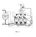
FIG. 4 , upon completion of filling the TDP spheres,fill valves FIG. 5 at which time the GSE may be disconnected and the system is ready for operation. In certain embodiments, valving to complete fill of the LH2 dewar prior to completion of the TDP spheres may be required for operational considerations. - As shown in
FIG. 6 , operation ofTDP 12 commences with opening ofpressurization valve 48c introducing GH2 pressure from the GH2 accumulator intoTDP sphere 20c. Thermal contraction of the gas results in a minor reduction in gas pressure of approximately 5 psia to 145 psia as shown. Opening ofsupply valve 28c provides LH2 flow fromTDP sphere 20c intosupply manifold 26 assisted byboost pump 30. LH2 flows throughheat exchanger 32 gasifying the LH2 into GH2 and flowing toaccumulator 38 for supply throughPFCD 40 to use by the engine and/or other accessory systems. Flow throughheat exchanger 32 increases operating pressure in the accumulator andTDP sphere 20c to nominal at 150 psia as shown inFIG. 7 . In the exemplary embodiments, a pressure regulator (not shown) maintains the nominal pressure of 150 psia in the accumulator. Pressures in the remaining two TDP spheres, 20b and 20a as well as the LH2 dewar andaccumulator 14 remain nominally at 25 psia. - When
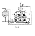
TDP sphere 20c is substantially depleted of LH2, as shown inFIG. 8 ,pressurization valve 48c is closed andsupply valve 28c is closed.Pressurization valve 48b is opened pressurizingTDP sphere 20b, with the gas pressure fluctuation to 145psia as shown, andsupply valve 28b is opened providing LH2 flow fromTDP sphere 20b to the supply manifold and throughpump 30 toheat exchanger 32 toaccumulator 38. Fillvalve 24c anddepressurization valve 52c are opened to commence refilling ofTDP sphere 20c. - As shown in
FIG. 9 , f low throughheat exchanger 32 increases operating pressure in the accumulator andTDP sphere 20b allowing pressure recovery to 150 psia is achieved inTDP sphere 20b andaccumulator 38. Depressurization ofTDP sphere 20c to approximately 25 psia for fill with flow through blow downmanifold 50 andheat exchanger 18 and back into theLH2 dewar 10 results in a slight pressure increase in accumulator andcondenser 14 of between 25 to 30 psia. LH2 flow from the dewar at 25 psia assisted byboost pump 16fills TDP sphere 20c asTDP sphere 20b is being depleted as shown inFIG. 10 . For the embodiment shown, LH2 saturation temperature and pressure results in the 25 psia dewar pressure. In alternative systems, alternate pressures and temperatures may be employed. - When
TDP sphere 20b is substantially depleted of LH2, as shown inFIG. 11 ,pressurization valve 48c is closed andsupply valve 28b is closed.Pressurization valve 48a is opened pressurizingTDP sphere 20a, with the gas pressure fluctuation to 145 psia as shown, and supply valve 28ab is opened providing LH2 flow fromTDP sphere 20a to the supply manifold and throughpump 30 toheat exchanger 32 toaccumulator 38. Fillvalve 24b anddepressurization valve 52b are opened to commence refilling ofTDP sphere 20b. - As shown in
FIG. 12 , pressure recovery to 150 psia is achieved inTDP sphere 20a andaccumulator 38. Depressurization ofTDP sphere 20b to approximately 25 psia for fill with flow through blow downmanifold 50 andheat exchanger 18 and back into theLH2 dewar 10 maintains the slight pressure increase in accumulator andcondenser 14 of between 25 to 30 psia. LH2 flow from the dewar assisted byboost pump 16fills TDP sphere 20b asTDP sphere 20a is being depleted as shown inFIG. 13 . - When
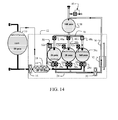
TDP sphere 20a is substantially depleted of LH2, as shown inFIG.14 ,pressurization valve 48a is closed andsupply valve 28a is closed.Pressurization valve 48c is opened pressurizingTDP sphere 20c, with the gas pressure fluctuation to 145 psia as shown, andsupply valve 28c is opened providing LH2 flow fromTDP sphere 20c to the supply manifold and throughpump 30 toheat exchanger 32 toaccumulator 38. Fillvalve 24a anddepressurization valve 52a are opened to commence refilling ofTDP sphere 20a. - As shown in
FIG. 15 , pressure recovery to 150 psia is achieved inTDP sphere 20c andaccumulator 38. Depressurization ofTDP sphere 20a to approximately 25 psia for fill with flow through blow downmanifold 50 andheat exchanger 18 and back into theLH2 dewar 10 maintains the slight pressure increase in accumulator andcondenser 14 of between 25 to 30 psia. LH2 flow from the dewar assisted byboost pump 16fills TDP sphere 20a asTDP sphere 20c is being depleted as shown inFIG. 16 placing the system in the condition as previously described with respect toFIG. 8 and the transition between the three TDP spheres rotates for continuous supply of GH2 toaccumulator 38 and the engine and or auxiliary systems. - For exemplary embodiments such as a HALE air vehicle application, the LH2 dewar(s) may be one or more 10 foot diameter spherical vacuum jacketed tanks. The TDP spheres are 6 inch diameter stainless steel vacuum jacketed tanks. In alternative embodiments, foam insulation or vacuum jacketing with additional insulation may be employed. The TDP spheres are not intended for long term LH2 storage. The sizing and thermal performance of the TDP spheres is selected to provide rapid cyclical LH2 fill, depletion and transfer to the liquid supply manifold over short time periods with minimal temperature change (i.e. warm-up) between cycles. For this exemplary sizing, cycle time for each TDP sphere is approximately 1 minute at nominal flow rates and may approach 20 seconds an maximum flow conditions. While three TDP spheres have been shown for this embodiment, two spheres or a larger number of spheres may be employed to desired thermal and pumping performance. Additionally, while discharge of one sphere and recharge of a depleted sphere are shown with comparable times in the described embodiment, sequential recharging of multiple spheres may be required to accommodate more rapid depletion times than refill times. Additionally, spherical tanks are employed in the exemplary embodiment, however, cylindrical or conformal tankage may be employed in alternative embodiments. In certain embodiments, a
heater assembly 56, as shown inFIG. 1 , may be employed in each TDP sphere to maintain a specific working temperature or thermal resistance. Cycle time on the TDP sphere fill and depletion is on the order of 1 minute with theheat exchanger 32 operating at about 2700 lbs/hour hot working fluid flow and about 47 lbs /hr H2 flow. Boost pumps 16 and 30 are electrically driven rotor pumps providing approximately ½ psi head rise for inducing flow of the LH2 in the system to avoid stagnation of flow.Level sensors 58 in each TDP spheres for determination of full and depleted conditions for cycle control as described may be silicon diode point sensors, capacitive sensors or other suitable devices. - Having now described various embodiments of the disclosure in detail as required by the patent statutes, those skilled in the art will recognize modifications and substitutions to the specific embodiments disclosed herein. Such modifications are within the scope and intent of the present disclosure as defined in the following claims.
Claims (11)
- A thermodynamic pump system for providing gaseous hydrogen comprising:an accumulator for storing pressurized gaseous hydrogen;a plurality of liquid hydrogen (LH2) tanks in fluid communication with an outlet of the accumulator and controlled for sequential pressurization; anda heat exchanger in fluid communication with the accumulator and in controlled fluid communication with the plurality of tanks for sequentially receiving LH2
- The thermodynamic pump defined in claim 1 further comprising a supply manifold interconnecting the plurality of tanks to the heat exchanger and having a plurality of supply valves for sequential supply of LH2 to the heat exchanger.
- The thermodynamic pump as defined in claim 2 further comprising a pressurization manifold interconnecting the accumulator to the plurality of tanks and having a plurality of pressurization valves for sequential pressurization of the tanks concurrent with the sequential supply of LH2.
- The thermodynamic pump as defined in claim 1 further comprising a fill manifold interconnecting the plurality of tanks to a dewar and having a plurality of fill valves for sequential fill of the tanks with LH2.
- A gaseous hydrogen (GH2) supply system comprising:a dewar for liquid hydrogen (LH2);a thermodynamic pump having a plurality of tanks receiving LH2 from the dewar and a heat exchanger providing GH2, said plurality of tanks sequentially providing LH2 to the heat exchanger and refilling from the dewar when depleted; and,an accumulator for supplying GH2, said accumulator receiving GH2 from the heat exchanger and providing pressurizing GH2 to the plurality of tanks.
- The GH2 supply system as defined in claim 5 further comprising:a supply manifold interconnecting the plurality of tanks to the heat exchanger and having a plurality of supply valves for sequential supply of LH2 to the heat exchanger;
- The thermodynamic pump as defined in claim 5 further comprising a fill manifold interconnecting the plurality of tanks to the dewar and having a plurality of fill valves for sequential fill of the tanks with LH2.
- A method of supplying an engine with hydrogen comprising:alternatingly connecting one of a plurality of liquid hydrogen tanks through a boost pump with an accumulator containing hydrogen gas providing a continuous flow of hydrogen gas to an engine.
- The method of claim 8 further comprising;
increasing the temperature of the hydrogen with a heat exchanger intermediate the tanks and accumulator; and
supplying hot working gas to the heat exchanger from the engine. - The method of claim 8 further comprising:interconnecting the tanks to the accumulator with a pressurization manifold having a plurality of pressurization valves connected to the tanks; and,operating the pressurization valves for control the sequential flow of hydrogen from the tanks.
- The method of claim 8 further comprising:operating a plurality of supply valves intermediate the heat exchanger and each of the liquid hydrogen tanks sequentially.
Applications Claiming Priority (1)
| Application Number | Priority Date | Filing Date | Title |
|---|---|---|---|
| US12/972,428 US8950195B2 (en) | 2010-12-18 | 2010-12-18 | Continuous flow thermodynamic pump |
Publications (3)
| Publication Number | Publication Date |
|---|---|
| EP2466188A2 true EP2466188A2 (en) | 2012-06-20 |
| EP2466188A3 EP2466188A3 (en) | 2017-08-23 |
| EP2466188B1 EP2466188B1 (en) | 2020-11-25 |
Family
ID=45350697
Family Applications (1)
| Application Number | Title | Priority Date | Filing Date |
|---|---|---|---|
| EP11193895.7A Active EP2466188B1 (en) | 2010-12-18 | 2011-12-15 | Continuous flow thermodynamic pump |
Country Status (5)
| Country | Link |
|---|---|
| US (2) | US8950195B2 (en) |
| EP (1) | EP2466188B1 (en) |
| JP (1) | JP5925472B2 (en) |
| CN (2) | CN102536516B (en) |
| CA (1) | CA2755479C (en) |
Cited By (6)
| Publication number | Priority date | Publication date | Assignee | Title |
|---|---|---|---|---|
| EP3181985A1 (en) * | 2015-12-15 | 2017-06-21 | Linde Aktiengesellschaft | Constant pressure storage unit |
| EP3889490A1 (en) * | 2020-04-03 | 2021-10-06 | Linde GmbH | Conveying device, storage container assembly and method |
| FR3133649A1 (en) * | 2022-03-15 | 2023-09-22 | Safran | Fuel delivery system and method |
| WO2024003858A3 (en) * | 2022-06-30 | 2024-02-22 | Saipem S.P.A. | Method for converting carbon dioxide into sng or lng and storing hydrogen |
| EP4365086A1 (en) * | 2022-11-07 | 2024-05-08 | General Electric Company | Integrated cryogenic hydrogen tank systems and methods for operating the same |
| DE102024114886A1 (en) | 2024-05-28 | 2025-07-10 | Daimler Truck AG | Tank system and method for supplying a consumer |
Families Citing this family (63)
| Publication number | Priority date | Publication date | Assignee | Title |
|---|---|---|---|---|
| DE102012013015A1 (en) * | 2012-06-29 | 2014-01-02 | Volkswagen Aktiengesellschaft | Method for fueling vehicle, particularly motor vehicle with fluid, particularly liquefied gas, such as propane, involves introducing fluid into vehicle and pumping fluid introduced in vehicle into tank by pump positioned in vehicle |
| KR101302307B1 (en) | 2012-07-16 | 2013-09-03 | 이지성 | Gas compressor |
| CA2878530C (en) * | 2012-07-26 | 2021-01-26 | Zodiac Aerotechnics | Removable storage for hydrogen on-board passenger transport vehicles such as aircraft |
| CN104653427B (en) * | 2015-01-04 | 2016-09-21 | 上海理工大学 | A kind of liquid pressurizing apparatus of thermal drivers |
| US9650996B2 (en) * | 2015-03-13 | 2017-05-16 | The Boeing Company | Valve controller for pressure stabilization |
| CN108368972B (en) * | 2015-12-14 | 2020-07-07 | 沃尔沃卡车集团 | Gas tank equipment |
| JP6637318B2 (en) * | 2016-02-02 | 2020-01-29 | 株式会社神戸製鋼所 | Gas supply device |
| CN107166161B (en) * | 2016-03-08 | 2023-08-04 | 中集安瑞科能源装备(苏州)有限公司 | Liquid unloading system of deep-cold pressure container |
| WO2018235099A1 (en) * | 2017-06-20 | 2018-12-27 | Thejo Engineering Ltd. | AIR JET |
| JP7069597B2 (en) * | 2017-08-10 | 2022-05-18 | トヨタ自動車株式会社 | High pressure container |
| JP2019163017A (en) * | 2018-03-20 | 2019-09-26 | 敏秀 淺川 | Flying object flying by electrically-driven air turbo fan engines |
| CN109630317B (en) * | 2018-12-06 | 2021-05-04 | 上海空间推进研究所 | Rail attitude control integrated space propulsion system based on electric pump |
| JP7659390B2 (en) | 2019-12-26 | 2025-04-09 | 住友化学株式会社 | Curable resin composition and display device |
| JP7406983B2 (en) | 2019-12-26 | 2023-12-28 | 住友化学株式会社 | Compositions and display devices |
| JP7701147B2 (en) | 2019-12-26 | 2025-07-01 | 住友化学株式会社 | display device |
| FR3106391B1 (en) * | 2020-01-17 | 2022-04-29 | Air Liquide | Installation and method for storing and distributing cryogenic fluid |
| JP7788218B2 (en) | 2020-03-31 | 2025-12-18 | 住友化学株式会社 | Curable resin composition and display device |
| JP7773859B2 (en) | 2020-03-31 | 2025-11-20 | 住友化学株式会社 | Curable resin composition and display device |
| JP7773858B2 (en) | 2020-03-31 | 2025-11-20 | 住友化学株式会社 | Curable resin composition and display device |
| FR3110936B1 (en) * | 2020-05-28 | 2022-06-17 | Safran | Device for regulating the pressure of an aircraft cryogenic fuel tank. |
| JP2022041899A (en) | 2020-08-31 | 2022-03-11 | 住友化学株式会社 | Resin composition, resin film, and display device |
| JP2022041900A (en) | 2020-08-31 | 2022-03-11 | 住友化学株式会社 | Laminates and display devices |
| JP2022041901A (en) | 2020-08-31 | 2022-03-11 | 住友化学株式会社 | Layered body and display device |
| DE102020128007A1 (en) * | 2020-10-23 | 2022-04-28 | Arianegroup Gmbh | Rocket propulsion, method and spacecraft |
| KR102446871B1 (en) * | 2020-12-31 | 2022-09-30 | 한국가스공사 | Emergency liquefied gas supply system and method |
| EP4274983B1 (en) * | 2021-01-06 | 2026-04-15 | Verne Inc. | Cryo-compressed hydrogen storage multi-tank systems and their thermal management |
| FR3120419A1 (en) * | 2021-03-07 | 2022-09-09 | Jean-Michel SCHULZ | Device with full control, management and steering authority for an on-board fuel or cryogenic fluid storage facility. |
| WO2022192386A1 (en) * | 2021-03-09 | 2022-09-15 | American Exchanger Services, Inc. | Energy storage using spherical pressure vessel assembly |
| GB2605586B (en) * | 2021-04-01 | 2025-03-05 | Thistle Rocketry Ltd | A pumping apparatus |
| JP2022170674A (en) | 2021-04-28 | 2022-11-10 | 住友化学株式会社 | Cured film and display device |
| KR20240004521A (en) | 2021-04-28 | 2024-01-11 | 스미또모 가가꾸 가부시키가이샤 | Cured film and display device |
| US11738990B2 (en) | 2021-06-16 | 2023-08-29 | Whitecap Industries, Inc. | Ullage float assembly for fuel tank and methods of use |
| EP4124577B1 (en) * | 2021-07-28 | 2025-09-03 | Airbus (S.A.S.) | Modular aircraft tank, tank system, aircraft and operation method |
| ES3032503T3 (en) * | 2021-08-23 | 2025-07-21 | Linde Gmbh | Method and conditioning device |
| US12158246B2 (en) * | 2021-08-24 | 2024-12-03 | Messer Industries Usa, Inc. | Depressurization system, apparatus and method for high pressure gas delivery |
| US12030611B2 (en) | 2021-10-14 | 2024-07-09 | ZeroAvia, Inc. | Lighter-than-air craft with hydrogen propulsion |
| US12139269B2 (en) * | 2021-10-14 | 2024-11-12 | ZeroAvia, Inc. | Capture of hydrogen boiloff |
| US12092042B2 (en) | 2021-10-20 | 2024-09-17 | General Electric Company | Hydrogen fuel system |
| US12351337B2 (en) | 2021-11-19 | 2025-07-08 | General Electric Company | Sub-coolers for refueling onboard cryogenic fuel tanks and methods for operating the same |
| US12352218B2 (en) | 2022-02-01 | 2025-07-08 | General Electric Company | Fuel supply system for a combustor |
| US11946419B2 (en) * | 2022-02-23 | 2024-04-02 | General Electric Company | Methods and apparatus to produce hydrogen gas turbine propulsion |
| US11604125B1 (en) * | 2022-03-07 | 2023-03-14 | Mustang Sampling, Llc | Liquid gas sample vaporizer conditioning system and method |
| JP2023152725A (en) | 2022-03-31 | 2023-10-17 | 住友化学株式会社 | Compositions, films and display devices |
| JP2023152724A (en) | 2022-03-31 | 2023-10-17 | 住友化学株式会社 | Compositions, films and display devices |
| JP2023152726A (en) | 2022-03-31 | 2023-10-17 | 住友化学株式会社 | Compositions, films and display devices |
| US12473862B2 (en) | 2022-05-13 | 2025-11-18 | General Electric Company | Purge system for a hydrogen fuel system |
| US20230399986A1 (en) * | 2022-06-09 | 2023-12-14 | General Electric Company | Monitoring systems for hydrogen fueled aircraft |
| WO2024020423A1 (en) * | 2022-07-21 | 2024-01-25 | ZeroAvia, Inc. | Capture of hydrogen boiloff |
| US12253033B2 (en) | 2022-10-04 | 2025-03-18 | General Electric Company | Hydrogen fuel leak detection system for a vehicle |
| EP4386253B1 (en) * | 2022-12-16 | 2025-08-27 | Eaton Intelligent Power Limited | Liquid delivery system |
| US12359773B2 (en) | 2023-03-16 | 2025-07-15 | General Electric Company | Systems, methods, and apparatus for refueling hydrogen aircraft |
| DE102023107756A1 (en) * | 2023-03-28 | 2024-10-02 | Mt Aerospace Ag | hydrogen tank system |
| FR3150262B1 (en) * | 2023-06-20 | 2025-05-09 | Air Liquide | Installation and process for supplying liquefied hydrogen |
| US11958625B1 (en) * | 2023-06-22 | 2024-04-16 | ZeroAvia, Inc. | Aerodynamic hydrogen tanks |
| US11933325B1 (en) * | 2023-08-11 | 2024-03-19 | ZeroAvia, Inc. | Thermal pumping of liquid hydrogen |
| FR3153332B1 (en) * | 2023-09-22 | 2025-08-15 | Safran | Fuel conditioning system for supplying an aircraft propulsion system with fuel from a cryogenic tank and associated method |
| US12492784B2 (en) * | 2023-10-17 | 2025-12-09 | Praxair Technology, Inc. | System and method for high flow rate liquid hydrogen tank filling |
| US20250189219A1 (en) * | 2023-12-06 | 2025-06-12 | Air Liquide Large Industries U.S. Lp | Method for pressurizing a liquid exiting a phase separator |
| EP4574677A1 (en) * | 2023-12-21 | 2025-06-25 | Airbus Operations GmbH | Fuel supply arrangement, vehicle, external energy conversion device and energy system comprising same |
| EP4606709A1 (en) * | 2024-02-23 | 2025-08-27 | GE Avio S.r.l. | Multi-phase fluid fuel systems and related methods |
| US20250290635A1 (en) * | 2024-03-12 | 2025-09-18 | Rtx Corporation | Liquid hydrogen fuel system with thermal compression |
| FR3162208A1 (en) * | 2024-05-16 | 2025-11-21 | Safran Aircraft Engines | Improved cryogenic fluid supply device for aeronautical turbojet engines |
| FR3164269A1 (en) * | 2024-07-03 | 2026-01-09 | Airbus Operations | Fuel supply system comprising at least two tanks of liquid hydrogen at different pressures |
Family Cites Families (21)
| Publication number | Priority date | Publication date | Assignee | Title |
|---|---|---|---|---|
| JPS6098299A (en) * | 1983-10-31 | 1985-06-01 | Nippon Sanso Kk | High pressure gas feeding method |
| FR2594209B1 (en) * | 1986-02-07 | 1988-05-13 | Carboxyque Francaise | PROCESS AND INSTALLATION FOR PROVIDING CARBONIC ANHYDRIDE UNDER HIGH PRESSURE |
| JPH068623B2 (en) * | 1988-09-24 | 1994-02-02 | 日野自動車工業株式会社 | Gas supply device for injection gas engine |
| IT1229858B (en) * | 1988-10-28 | 1991-09-13 | Snam Progetti | PROCEDURE FOR PUMPING A MULTI-PHASE LIQUID GAS MIXTURE BY USING A PUMP |
| US5325894A (en) * | 1992-12-07 | 1994-07-05 | Chicago Bridge & Iron Technical Services Company | Method and apparatus for fueling vehicles with liquefied natural gas |
| US5687776A (en) * | 1992-12-07 | 1997-11-18 | Chicago Bridge & Iron Technical Services Company | Method and apparatus for fueling vehicles with liquefied cryogenic fuel |
| US5329777A (en) * | 1993-06-24 | 1994-07-19 | The Boc Group, Inc. | Cryogenic storage and delivery method and apparatus |
| US5454408A (en) * | 1993-08-11 | 1995-10-03 | Thermo Power Corporation | Variable-volume storage and dispensing apparatus for compressed natural gas |
| JP2561622B2 (en) * | 1994-03-11 | 1996-12-11 | 福岡酸素株式会社 | Method and apparatus for stable supply of liquefied petroleum gas |
| US5678411A (en) * | 1995-04-26 | 1997-10-21 | Ebara Corporation | Liquefied gas supply system |
| US7257940B1 (en) * | 2001-06-12 | 2007-08-21 | Knight Andrew F | Device and method for pumping a fluid |
| WO2005010427A1 (en) * | 2003-07-25 | 2005-02-03 | Toyota Jidosha Kabushiki Kaisha | Gas supply system |
| JP2005330979A (en) * | 2004-05-18 | 2005-12-02 | N Energy:Kk | LIQUID GAS SUPPLY METHOD AND LIQUID GAS SUPPLY DEVICE |
| US7219682B2 (en) * | 2004-08-26 | 2007-05-22 | Seaone Maritime Corp. | Liquid displacement shuttle system and method |
| US7624770B2 (en) * | 2004-09-23 | 2009-12-01 | The Boc Group, Inc. | Intelligent compressor strategy to support hydrogen fueling |
| US7325561B2 (en) * | 2004-12-02 | 2008-02-05 | Honda Motor Co., Ltd. | Hydrogen vehicle gas utilization and refueling system |
| DE112006000247B4 (en) * | 2005-01-26 | 2010-09-02 | Toyota Jidosha Kabushiki Kaisha, Toyota-shi | The fuel tank system |
| US7806365B2 (en) * | 2006-07-05 | 2010-10-05 | The Boeing Company | Long endurance hydrogen powered vehicle |
| WO2008074075A1 (en) * | 2006-12-21 | 2008-06-26 | Mosaic Technologies Pty Ltd | A compressed gas transfer system |
| US8726676B2 (en) * | 2007-05-17 | 2014-05-20 | The Boeing Company | Thermodynamic pump for cryogenic fueled devices |
| US8789379B2 (en) * | 2009-05-12 | 2014-07-29 | The Boeing Company | Two-phase hydrogen pump and method |
-
2010
- 2010-12-18 US US12/972,428 patent/US8950195B2/en active Active
-
2011
- 2011-10-18 CA CA 2755479 patent/CA2755479C/en active Active
- 2011-11-30 JP JP2011261366A patent/JP5925472B2/en active Active
- 2011-12-15 EP EP11193895.7A patent/EP2466188B1/en active Active
- 2011-12-19 CN CN201110439048.9A patent/CN102536516B/en active Active
- 2011-12-19 CN CN201611025017.8A patent/CN106678541B/en active Active
-
2015
- 2015-01-16 US US14/599,390 patent/US20150121905A1/en not_active Abandoned
Non-Patent Citations (1)
| Title |
|---|
| None |
Cited By (6)
| Publication number | Priority date | Publication date | Assignee | Title |
|---|---|---|---|---|
| EP3181985A1 (en) * | 2015-12-15 | 2017-06-21 | Linde Aktiengesellschaft | Constant pressure storage unit |
| EP3889490A1 (en) * | 2020-04-03 | 2021-10-06 | Linde GmbH | Conveying device, storage container assembly and method |
| FR3133649A1 (en) * | 2022-03-15 | 2023-09-22 | Safran | Fuel delivery system and method |
| WO2024003858A3 (en) * | 2022-06-30 | 2024-02-22 | Saipem S.P.A. | Method for converting carbon dioxide into sng or lng and storing hydrogen |
| EP4365086A1 (en) * | 2022-11-07 | 2024-05-08 | General Electric Company | Integrated cryogenic hydrogen tank systems and methods for operating the same |
| DE102024114886A1 (en) | 2024-05-28 | 2025-07-10 | Daimler Truck AG | Tank system and method for supplying a consumer |
Also Published As
| Publication number | Publication date |
|---|---|
| EP2466188A3 (en) | 2017-08-23 |
| US20120156059A1 (en) | 2012-06-21 |
| US20150121905A1 (en) | 2015-05-07 |
| US8950195B2 (en) | 2015-02-10 |
| CA2755479C (en) | 2014-09-16 |
| CN106678541A (en) | 2017-05-17 |
| CA2755479A1 (en) | 2012-06-18 |
| CN106678541B (en) | 2019-12-06 |
| EP2466188B1 (en) | 2020-11-25 |
| JP2012132558A (en) | 2012-07-12 |
| CN102536516B (en) | 2016-12-21 |
| JP5925472B2 (en) | 2016-05-25 |
| CN102536516A (en) | 2012-07-04 |
Similar Documents
| Publication | Publication Date | Title |
|---|---|---|
| CA2755479C (en) | Continuous flow thermodynamic pump | |
| Brunner et al. | Cryo‐compressed hydrogen storage | |
| US8281566B2 (en) | Thermally-integrated fluid storage and pressurization system | |
| US7743797B2 (en) | Gas flow management equipment for high pressure storage tanks | |
| EP1722153B1 (en) | Gas cooling using a melting/solidifying medium for high pressure storage tanks for compressed natural gas or hydrogen | |
| CN103950554A (en) | Spacecraft propellant in-orbit filling system and spacecraft propellant in-orbit filling method | |
| US20110262842A1 (en) | System and method for storing and discharging heat in a vehicle | |
| IT202100004298A1 (en) | HYDROGEN COMPRESSION SYSTEM AND METHOD OF PRODUCING HYDROGEN AT LOW TEMPERATURE AND HIGH PRESSURE | |
| JP2013527385A (en) | Hydrogen distribution system and method | |
| JP4554966B2 (en) | Hydrogen gas filling method and hydrogen gas filling device | |
| EP2837873A2 (en) | Method and installation for producing pressurised gas | |
| CN215674743U (en) | Mixed filling system applied to liquid hydrogen filling station | |
| GB2628992A (en) | Apparatus | |
| RU2447313C1 (en) | Restartable liquid-propellant engine (versions) | |
| CN115649492A (en) | A cryogenic propellant integrated fluid system based on energy-fluid matching design | |
| US11933325B1 (en) | Thermal pumping of liquid hydrogen | |
| Millis et al. | Hydrogen fuel system design trades for high-altitude long-endurance remotely-operated aircraft | |
| EP4392657B1 (en) | Fuel system for a power plant | |
| KR102379650B1 (en) | Ambient type high-pressure hydrogen vaporizer and hydrogen charging apparatus using the same | |
| CN215949674U (en) | A liquid rocket storage tank electric heating pressurization system | |
| CN117267623A (en) | Multi-pump parallel hydrogen supply type liquid hydrogen pressurized gasification system and operation method | |
| US20260063081A1 (en) | Gas turbine engine fuel system | |
| US20240240759A1 (en) | Multi-cryogenic storage system | |
| CN121382472A (en) | Double-component liquid rocket heating pressurization system and method | |
| Harrington | High Performance Lox Hydrogen Upper Stage with Pistonless Pump |
Legal Events
| Date | Code | Title | Description |
|---|---|---|---|
| PUAI | Public reference made under article 153(3) epc to a published international application that has entered the european phase |
Free format text: ORIGINAL CODE: 0009012 |
|
| 17P | Request for examination filed |
Effective date: 20111215 |
|
| AK | Designated contracting states |
Kind code of ref document: A2 Designated state(s): AL AT BE BG CH CY CZ DE DK EE ES FI FR GB GR HR HU IE IS IT LI LT LU LV MC MK MT NL NO PL PT RO RS SE SI SK SM TR |
|
| AX | Request for extension of the european patent |
Extension state: BA ME |
|
| RIC1 | Information provided on ipc code assigned before grant |
Ipc: F17C 5/06 20060101AFI20170313BHEP Ipc: F17C 9/02 20060101ALI20170313BHEP |
|
| PUAL | Search report despatched |
Free format text: ORIGINAL CODE: 0009013 |
|
| AK | Designated contracting states |
Kind code of ref document: A3 Designated state(s): AL AT BE BG CH CY CZ DE DK EE ES FI FR GB GR HR HU IE IS IT LI LT LU LV MC MK MT NL NO PL PT RO RS SE SI SK SM TR |
|
| AX | Request for extension of the european patent |
Extension state: BA ME |
|
| RIC1 | Information provided on ipc code assigned before grant |
Ipc: F17C 5/06 20060101AFI20170720BHEP Ipc: F17C 9/02 20060101ALI20170720BHEP |
|
| STAA | Information on the status of an ep patent application or granted ep patent |
Free format text: STATUS: EXAMINATION IS IN PROGRESS |
|
| 17Q | First examination report despatched |
Effective date: 20190222 |
|
| GRAP | Despatch of communication of intention to grant a patent |
Free format text: ORIGINAL CODE: EPIDOSNIGR1 |
|
| STAA | Information on the status of an ep patent application or granted ep patent |
Free format text: STATUS: GRANT OF PATENT IS INTENDED |
|
| INTG | Intention to grant announced |
Effective date: 20200708 |
|
| RIN1 | Information on inventor provided before grant (corrected) |
Inventor name: WATTS, DANIEL A. |
|
| GRAS | Grant fee paid |
Free format text: ORIGINAL CODE: EPIDOSNIGR3 |
|
| GRAA | (expected) grant |
Free format text: ORIGINAL CODE: 0009210 |
|
| STAA | Information on the status of an ep patent application or granted ep patent |
Free format text: STATUS: THE PATENT HAS BEEN GRANTED |
|
| AK | Designated contracting states |
Kind code of ref document: B1 Designated state(s): AL AT BE BG CH CY CZ DE DK EE ES FI FR GB GR HR HU IE IS IT LI LT LU LV MC MK MT NL NO PL PT RO RS SE SI SK SM TR |
|
| REG | Reference to a national code |
Ref country code: GB Ref legal event code: FG4D |
|
| REG | Reference to a national code |
Ref country code: CH Ref legal event code: EP |
|
| REG | Reference to a national code |
Ref country code: DE Ref legal event code: R096 Ref document number: 602011069406 Country of ref document: DE |
|
| REG | Reference to a national code |
Ref country code: AT Ref legal event code: REF Ref document number: 1338742 Country of ref document: AT Kind code of ref document: T Effective date: 20201215 |
|
| REG | Reference to a national code |
Ref country code: IE Ref legal event code: FG4D |
|
| REG | Reference to a national code |
Ref country code: AT Ref legal event code: MK05 Ref document number: 1338742 Country of ref document: AT Kind code of ref document: T Effective date: 20201125 |
|
| REG | Reference to a national code |
Ref country code: NL Ref legal event code: MP Effective date: 20201125 |
|
| PG25 | Lapsed in a contracting state [announced via postgrant information from national office to epo] |
Ref country code: RS Free format text: LAPSE BECAUSE OF FAILURE TO SUBMIT A TRANSLATION OF THE DESCRIPTION OR TO PAY THE FEE WITHIN THE PRESCRIBED TIME-LIMIT Effective date: 20201125 Ref country code: FI Free format text: LAPSE BECAUSE OF FAILURE TO SUBMIT A TRANSLATION OF THE DESCRIPTION OR TO PAY THE FEE WITHIN THE PRESCRIBED TIME-LIMIT Effective date: 20201125 Ref country code: NO Free format text: LAPSE BECAUSE OF FAILURE TO SUBMIT A TRANSLATION OF THE DESCRIPTION OR TO PAY THE FEE WITHIN THE PRESCRIBED TIME-LIMIT Effective date: 20210225 Ref country code: PT Free format text: LAPSE BECAUSE OF FAILURE TO SUBMIT A TRANSLATION OF THE DESCRIPTION OR TO PAY THE FEE WITHIN THE PRESCRIBED TIME-LIMIT Effective date: 20210325 Ref country code: GR Free format text: LAPSE BECAUSE OF FAILURE TO SUBMIT A TRANSLATION OF THE DESCRIPTION OR TO PAY THE FEE WITHIN THE PRESCRIBED TIME-LIMIT Effective date: 20210226 |
|
| PG25 | Lapsed in a contracting state [announced via postgrant information from national office to epo] |
Ref country code: LV Free format text: LAPSE BECAUSE OF FAILURE TO SUBMIT A TRANSLATION OF THE DESCRIPTION OR TO PAY THE FEE WITHIN THE PRESCRIBED TIME-LIMIT Effective date: 20201125 Ref country code: PL Free format text: LAPSE BECAUSE OF FAILURE TO SUBMIT A TRANSLATION OF THE DESCRIPTION OR TO PAY THE FEE WITHIN THE PRESCRIBED TIME-LIMIT Effective date: 20201125 Ref country code: SE Free format text: LAPSE BECAUSE OF FAILURE TO SUBMIT A TRANSLATION OF THE DESCRIPTION OR TO PAY THE FEE WITHIN THE PRESCRIBED TIME-LIMIT Effective date: 20201125 Ref country code: AT Free format text: LAPSE BECAUSE OF FAILURE TO SUBMIT A TRANSLATION OF THE DESCRIPTION OR TO PAY THE FEE WITHIN THE PRESCRIBED TIME-LIMIT Effective date: 20201125 Ref country code: BG Free format text: LAPSE BECAUSE OF FAILURE TO SUBMIT A TRANSLATION OF THE DESCRIPTION OR TO PAY THE FEE WITHIN THE PRESCRIBED TIME-LIMIT Effective date: 20210225 Ref country code: IS Free format text: LAPSE BECAUSE OF FAILURE TO SUBMIT A TRANSLATION OF THE DESCRIPTION OR TO PAY THE FEE WITHIN THE PRESCRIBED TIME-LIMIT Effective date: 20210325 |
|
| REG | Reference to a national code |
Ref country code: LT Ref legal event code: MG9D |
|
| PG25 | Lapsed in a contracting state [announced via postgrant information from national office to epo] |
Ref country code: HR Free format text: LAPSE BECAUSE OF FAILURE TO SUBMIT A TRANSLATION OF THE DESCRIPTION OR TO PAY THE FEE WITHIN THE PRESCRIBED TIME-LIMIT Effective date: 20201125 |
|
| PG25 | Lapsed in a contracting state [announced via postgrant information from national office to epo] |
Ref country code: SK Free format text: LAPSE BECAUSE OF FAILURE TO SUBMIT A TRANSLATION OF THE DESCRIPTION OR TO PAY THE FEE WITHIN THE PRESCRIBED TIME-LIMIT Effective date: 20201125 Ref country code: RO Free format text: LAPSE BECAUSE OF FAILURE TO SUBMIT A TRANSLATION OF THE DESCRIPTION OR TO PAY THE FEE WITHIN THE PRESCRIBED TIME-LIMIT Effective date: 20201125 Ref country code: LT Free format text: LAPSE BECAUSE OF FAILURE TO SUBMIT A TRANSLATION OF THE DESCRIPTION OR TO PAY THE FEE WITHIN THE PRESCRIBED TIME-LIMIT Effective date: 20201125 Ref country code: EE Free format text: LAPSE BECAUSE OF FAILURE TO SUBMIT A TRANSLATION OF THE DESCRIPTION OR TO PAY THE FEE WITHIN THE PRESCRIBED TIME-LIMIT Effective date: 20201125 Ref country code: CZ Free format text: LAPSE BECAUSE OF FAILURE TO SUBMIT A TRANSLATION OF THE DESCRIPTION OR TO PAY THE FEE WITHIN THE PRESCRIBED TIME-LIMIT Effective date: 20201125 Ref country code: SM Free format text: LAPSE BECAUSE OF FAILURE TO SUBMIT A TRANSLATION OF THE DESCRIPTION OR TO PAY THE FEE WITHIN THE PRESCRIBED TIME-LIMIT Effective date: 20201125 |
|
| REG | Reference to a national code |
Ref country code: CH Ref legal event code: PL |
|
| REG | Reference to a national code |
Ref country code: DE Ref legal event code: R097 Ref document number: 602011069406 Country of ref document: DE |
|
| PG25 | Lapsed in a contracting state [announced via postgrant information from national office to epo] |
Ref country code: DK Free format text: LAPSE BECAUSE OF FAILURE TO SUBMIT A TRANSLATION OF THE DESCRIPTION OR TO PAY THE FEE WITHIN THE PRESCRIBED TIME-LIMIT Effective date: 20201125 Ref country code: MC Free format text: LAPSE BECAUSE OF FAILURE TO SUBMIT A TRANSLATION OF THE DESCRIPTION OR TO PAY THE FEE WITHIN THE PRESCRIBED TIME-LIMIT Effective date: 20201125 |
|
| REG | Reference to a national code |
Ref country code: BE Ref legal event code: MM Effective date: 20201231 |
|
| PLBE | No opposition filed within time limit |
Free format text: ORIGINAL CODE: 0009261 |
|
| STAA | Information on the status of an ep patent application or granted ep patent |
Free format text: STATUS: NO OPPOSITION FILED WITHIN TIME LIMIT |
|
| PG25 | Lapsed in a contracting state [announced via postgrant information from national office to epo] |
Ref country code: AL Free format text: LAPSE BECAUSE OF FAILURE TO SUBMIT A TRANSLATION OF THE DESCRIPTION OR TO PAY THE FEE WITHIN THE PRESCRIBED TIME-LIMIT Effective date: 20201125 Ref country code: IT Free format text: LAPSE BECAUSE OF FAILURE TO SUBMIT A TRANSLATION OF THE DESCRIPTION OR TO PAY THE FEE WITHIN THE PRESCRIBED TIME-LIMIT Effective date: 20201125 Ref country code: IE Free format text: LAPSE BECAUSE OF NON-PAYMENT OF DUE FEES Effective date: 20201215 Ref country code: LU Free format text: LAPSE BECAUSE OF NON-PAYMENT OF DUE FEES Effective date: 20201215 Ref country code: NL Free format text: LAPSE BECAUSE OF FAILURE TO SUBMIT A TRANSLATION OF THE DESCRIPTION OR TO PAY THE FEE WITHIN THE PRESCRIBED TIME-LIMIT Effective date: 20201125 |
|
| 26N | No opposition filed |
Effective date: 20210826 |
|
| PG25 | Lapsed in a contracting state [announced via postgrant information from national office to epo] |
Ref country code: SI Free format text: LAPSE BECAUSE OF FAILURE TO SUBMIT A TRANSLATION OF THE DESCRIPTION OR TO PAY THE FEE WITHIN THE PRESCRIBED TIME-LIMIT Effective date: 20201125 Ref country code: LI Free format text: LAPSE BECAUSE OF NON-PAYMENT OF DUE FEES Effective date: 20201231 Ref country code: CH Free format text: LAPSE BECAUSE OF NON-PAYMENT OF DUE FEES Effective date: 20201231 Ref country code: ES Free format text: LAPSE BECAUSE OF FAILURE TO SUBMIT A TRANSLATION OF THE DESCRIPTION OR TO PAY THE FEE WITHIN THE PRESCRIBED TIME-LIMIT Effective date: 20201125 |
|
| PG25 | Lapsed in a contracting state [announced via postgrant information from national office to epo] |
Ref country code: IS Free format text: LAPSE BECAUSE OF FAILURE TO SUBMIT A TRANSLATION OF THE DESCRIPTION OR TO PAY THE FEE WITHIN THE PRESCRIBED TIME-LIMIT Effective date: 20210325 Ref country code: TR Free format text: LAPSE BECAUSE OF FAILURE TO SUBMIT A TRANSLATION OF THE DESCRIPTION OR TO PAY THE FEE WITHIN THE PRESCRIBED TIME-LIMIT Effective date: 20201125 Ref country code: MT Free format text: LAPSE BECAUSE OF FAILURE TO SUBMIT A TRANSLATION OF THE DESCRIPTION OR TO PAY THE FEE WITHIN THE PRESCRIBED TIME-LIMIT Effective date: 20201125 Ref country code: CY Free format text: LAPSE BECAUSE OF FAILURE TO SUBMIT A TRANSLATION OF THE DESCRIPTION OR TO PAY THE FEE WITHIN THE PRESCRIBED TIME-LIMIT Effective date: 20201125 |
|
| PG25 | Lapsed in a contracting state [announced via postgrant information from national office to epo] |
Ref country code: MK Free format text: LAPSE BECAUSE OF FAILURE TO SUBMIT A TRANSLATION OF THE DESCRIPTION OR TO PAY THE FEE WITHIN THE PRESCRIBED TIME-LIMIT Effective date: 20201125 |
|
| PG25 | Lapsed in a contracting state [announced via postgrant information from national office to epo] |
Ref country code: BE Free format text: LAPSE BECAUSE OF NON-PAYMENT OF DUE FEES Effective date: 20201231 |
|
| P01 | Opt-out of the competence of the unified patent court (upc) registered |
Effective date: 20230516 |
|
| PGFP | Annual fee paid to national office [announced via postgrant information from national office to epo] |
Ref country code: GB Payment date: 20251229 Year of fee payment: 15 |
|
| PGFP | Annual fee paid to national office [announced via postgrant information from national office to epo] |
Ref country code: FR Payment date: 20251226 Year of fee payment: 15 |
|
| PGFP | Annual fee paid to national office [announced via postgrant information from national office to epo] |
Ref country code: DE Payment date: 20251229 Year of fee payment: 15 |