EP2466120A2 - System and method for performing an external inspection on a wind turbine rotor blade - Google Patents
System and method for performing an external inspection on a wind turbine rotor blade Download PDFInfo
- Publication number
- EP2466120A2 EP2466120A2 EP11192782A EP11192782A EP2466120A2 EP 2466120 A2 EP2466120 A2 EP 2466120A2 EP 11192782 A EP11192782 A EP 11192782A EP 11192782 A EP11192782 A EP 11192782A EP 2466120 A2 EP2466120 A2 EP 2466120A2
- Authority
- EP
- European Patent Office
- Prior art keywords
- frame
- rotor blade
- sensing device
- spacer
- spacer arm
- Prior art date
- Legal status (The legal status is an assumption and is not a legal conclusion. Google has not performed a legal analysis and makes no representation as to the accuracy of the status listed.)
- Withdrawn
Links
Images


Classifications
-
- G—PHYSICS
- G01—MEASURING; TESTING
- G01M—TESTING STATIC OR DYNAMIC BALANCE OF MACHINES OR STRUCTURES; TESTING OF STRUCTURES OR APPARATUS, NOT OTHERWISE PROVIDED FOR
- G01M5/00—Investigating the elasticity of structures, e.g. deflection of bridges or air-craft wings
- G01M5/0016—Investigating the elasticity of structures, e.g. deflection of bridges or air-craft wings of aircraft wings or blades
-
- F—MECHANICAL ENGINEERING; LIGHTING; HEATING; WEAPONS; BLASTING
- F03—MACHINES OR ENGINES FOR LIQUIDS; WIND, SPRING, OR WEIGHT MOTORS; PRODUCING MECHANICAL POWER OR A REACTIVE PROPULSIVE THRUST, NOT OTHERWISE PROVIDED FOR
- F03D—WIND MOTORS
- F03D17/00—Monitoring or testing of wind motors, e.g. diagnostics
-
- F—MECHANICAL ENGINEERING; LIGHTING; HEATING; WEAPONS; BLASTING
- F03—MACHINES OR ENGINES FOR LIQUIDS; WIND, SPRING, OR WEIGHT MOTORS; PRODUCING MECHANICAL POWER OR A REACTIVE PROPULSIVE THRUST, NOT OTHERWISE PROVIDED FOR
- F03D—WIND MOTORS
- F03D80/00—Details, components or accessories not provided for in groups F03D1/00 - F03D17/00
- F03D80/50—Maintenance or repair
-
- G—PHYSICS
- G01—MEASURING; TESTING
- G01M—TESTING STATIC OR DYNAMIC BALANCE OF MACHINES OR STRUCTURES; TESTING OF STRUCTURES OR APPARATUS, NOT OTHERWISE PROVIDED FOR
- G01M11/00—Testing of optical apparatus; Testing structures by optical methods not otherwise provided for
- G01M11/08—Testing mechanical properties
- G01M11/081—Testing mechanical properties by using a contact-less detection method, i.e. with a camera
-
- G—PHYSICS
- G01—MEASURING; TESTING
- G01M—TESTING STATIC OR DYNAMIC BALANCE OF MACHINES OR STRUCTURES; TESTING OF STRUCTURES OR APPARATUS, NOT OTHERWISE PROVIDED FOR
- G01M5/00—Investigating the elasticity of structures, e.g. deflection of bridges or air-craft wings
- G01M5/0033—Investigating the elasticity of structures, e.g. deflection of bridges or air-craft wings by determining damage, crack or wear
-
- G—PHYSICS
- G01—MEASURING; TESTING
- G01M—TESTING STATIC OR DYNAMIC BALANCE OF MACHINES OR STRUCTURES; TESTING OF STRUCTURES OR APPARATUS, NOT OTHERWISE PROVIDED FOR
- G01M5/00—Investigating the elasticity of structures, e.g. deflection of bridges or air-craft wings
- G01M5/0091—Investigating the elasticity of structures, e.g. deflection of bridges or air-craft wings by using electromagnetic excitation or detection
-
- Y—GENERAL TAGGING OF NEW TECHNOLOGICAL DEVELOPMENTS; GENERAL TAGGING OF CROSS-SECTIONAL TECHNOLOGIES SPANNING OVER SEVERAL SECTIONS OF THE IPC; TECHNICAL SUBJECTS COVERED BY FORMER USPC CROSS-REFERENCE ART COLLECTIONS [XRACs] AND DIGESTS
- Y02—TECHNOLOGIES OR APPLICATIONS FOR MITIGATION OR ADAPTATION AGAINST CLIMATE CHANGE
- Y02E—REDUCTION OF GREENHOUSE GAS [GHG] EMISSIONS, RELATED TO ENERGY GENERATION, TRANSMISSION OR DISTRIBUTION
- Y02E10/00—Energy generation through renewable energy sources
- Y02E10/70—Wind energy
- Y02E10/72—Wind turbines with rotation axis in wind direction
Definitions
- the present subject matter relates generally to wind turbines and, more particularly, to a system and method for performing an external inspection on a wind turbine rotor blade.
- a modem wind turbine typically includes a tower, generator, gearbox, nacelle, and one or more rotor blades.
- the rotor blades capture kinetic energy from wind using known foil principles and transmit the kinetic energy through rotational energy to turn a shaft coupling the rotor blades to a gearbox, or if a gearbox is not used, directly to the generator.
- the generator then converts the mechanical energy to electrical energy that may be deployed to a utility grid.
- wind turbine components is critical to the ongoing operation of a wind turbine.
- maintenance operations such as inspections
- visual inspections of the exterior of a rotor blade may be performed to identify cracks and other potential defects.
- conventional methods require the use of a telescope disposed adjacent to the base of the wind turbine.
- an operator must typically scan the entire length of the blade looking for defects.
- the use of such an inspection method is generally very time consuming. Additionally, it is often difficult to detect small surface defects using the telescope.
- the present subject matter discloses a system for performing an external inspection on a rotor blade of a wind turbine.
- the system may generally include a frame configured to extend at least partially around an outer perimeter of the rotor blade and a sensing device coupled to the frame. Additionally, the system may include first and second spacer arms extending from the frame. The first spacer arm may be configured to contact a pressure side surface of the rotor blade. The second spacer arm may be configured to contact a suction side surface of the rotor blade.
- the present subject matter discloses a method for performing an external inspection on a rotor blade.
- the method may generally include positioning a frame around at least a portion of an outer perimeter of the rotor blade, coupling a sensing device to the frame, moving the frame along the span of the rotor blade, contacting a first spacer arm against a pressure side surface of the rotor blade as the frame is moved along the span of the rotor blade and contacting a second spacer arm against a suction side surface of the rotor blade as said frame is moved along the span of the rotor blade.
- a system for performing an external inspection on a rotor blade.
- a system includes a frame configured to be raised and lowered along the span of the rotor blade.
- One or more sensing devices may be coupled to the frame in order to provide information regarding the condition of the blade.
- a one or more spacer arms may extend inwardly from the frame so as to space the frame apart from the rotor blade.
- inspection refers to any operation, action and/or test performed on a wind turbine that is designed to monitor, sense, locate, measure and/or detect a condition of any component of the wind turbine and, particularly, a condition of a rotor blade of the wind turbine.
- inspections may include, but are not limited to, visual inspections of the exterior of the rotor blades, optical nondestructive evaluation (NDE) tests (e.g., shearography tests), thermography tests and other related operations/tests.
- NDE optical nondestructive evaluation
- sensing device may refer to any suitable sensor, equipment, mechanism and/or any other item that may be utilized to monitor, sense, locate, measure and/or detect a condition of a component of a wind turbine.
- sensing devices may include, but are not limited to, visual cameras, infrared cameras, ultraviolet cameras, video cameras, other suitable cameras, ultrasonic detectors, x-ray detectors, other suitable imaging devices and sensors, light sources (e.g., a light-emitting diode (LED) array), proximity sensors, position sensors, displacement sensors, linear encoders, measurement devices, laser scaling devices, magnetic sensing equipment, ultrasound equipment, microwave instrumentation, active infrared equipment, optical NDE testing equipment, thermography testing equipment and/or any other suitable equipment, sensors, mechanisms and/or items.
- light sources e.g., a light-emitting diode (LED) array
- proximity sensors e.g., a light-emitting diode (LED) array
- proximity sensors e.g., a light-emitting diode (LED) array
- proximity sensors e.g., a light-emitting diode (LED) array
- proximity sensors e.g., a light-emitting di
- the system of the present subject matter may be configured to perform an external visual inspection on a wind turbine rotor blade.
- the disclosed sensing device(s) may comprise one or more suitable optical and/or imaging devices configured to monitor, locate, sense, measure and/or detect such anomalies.
- the sensing device(s) may comprise one or more remote controlled pan tilt zoom (PTZ) cameras configured to capture images of the exterior of a rotor blade.
- PTZ pan tilt zoom
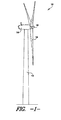
- FIG. 1 illustrates a wind turbine 10 of conventional construction.
- the wind turbine 10 generally includes a tower 12 with a nacelle 14 mounted thereon.
- a plurality of rotor blades 16 are mounted to a rotor hub 18, which is, in turn, connected to a main flange that turns a main rotor shaft.
- the wind turbine power generation and control components are housed within the nacelle 14.
- the wind turbine 10 of FIG. 1 is generally provided for illustrative purposes only to place the present subject matter in an exemplary field of use. Thus, it should be appreciated that the present subject matter is not limited to any particular type of wind turbine configuration.
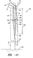
- FIGS. 2-5 there is illustrated one embodiment of a system 100 for performing an external inspection on a rotor blade 16 of a wind turbine 10.
- FIG. 2 illustrates a partial, perspective view of one embodiment of the system 100 installed on the exterior of the rotor blade 16 in accordance with aspects of the present subject matter.
- FIGS. 3-5 illustrate respective top, side and edge views of a portion of the system shown in FIG. 2 .
- the system 100 may include a frame 102 configured to be raised and lowered along the span 104 of the rotor blade 16. Additionally, one or more sensing devices 106 may be coupled to the frame 102 for monitoring, sensing, measuring and/or detecting a condition(s) of the rotor blade 16 as the frame 102 is moved along the blade 16.
- the system may also include one or more spacer arms 108, 110 extending inwardly from the frame 102. The spacer arm(s) 108, 110 may generally be configured to contact the outer perimeter of the rotor blade 16 so as to maintain a gap 112 between the outer perimeter and an inner surface 114 of the frame 102.
- the outer perimeter of the rotor blade 16 may generally be defined by pressure and suction side surfaces 116, 118 extending between the leading and trailing edges 120, 122 of the blade 16.
- the frame 102 of the disclosed system 100 may generally serve as a carriage for transporting the sensing device(s) 106 along the span 104 of the rotor blade 16.
- the frame 102 may be configured to transport suitable optical equipment (e.g., one or more cameras and the like) up and down the blade 16 to permit images and other information regarding the exterior of the blade 16 to be captured.
- suitable optical equipment e.g., one or more cameras and the like
- the frame 102 may be configured to transport a combination of different types of sensing devices 106 along the span 104 of the rotor blade 16, such by transporting one or more cameras together with light sources, proximity sensors, measurement devices, laser scaling devices and the like up and down the blade 16.
- the frame 102 may generally be raised and lowered along the rotor blade 16 using any suitable means known in the art.
- one or more cables 124, 126 may be attached to the frame 102 to allow it to be moved vertically along the span 104 of the rotor blade 16.
- a first cable 124 may be attached to a first end 128 of the frame 102 and a second cable 126 may be attached to a second end 130 of the frame 102, with each of the cables 124, 126 extending upwardly to an uptower component of the rotor blade 16 (e.g., the nacelle 14 and/or the hub 18 of the wind turbine 10).
- the cables 124, 126 may then be vertically displaced using any suitable lifting method and/or mechanism.
- the cables 124, 126 may be pulled and lowered manually, such as by having one or more operators manipulate the vertical position of the frame from a location on or within the nacelle 14 and/or the hub 18.
- the cables 124, 126 may be vertically displaced using one or more lifting mechanisms and/or pulley mechanisms (not shown) (e.g., electric winches, pulleys and/or any other similar devices) mounted on or within the nacelle 14, the hub 18 and/or at any other suitable location.
- one or more drop cables 132 may also extend downwardly from the frame 102 to allow the position of the frame 102 to be manipulated from a location adjacent to the support surface 134 of the wind turbine 10.
- cables 132 may extend between the ends 128, 130 of the frame 102 and the support surface 134.
- the disclosed frame 102 may generally have any suitable configuration that allows the frame 102 to be positioned proximal to the rotor blade 16 as it is raised and lowered.
- the frame 102 may defme a closed shaped extending around the entire outer perimeter of the rotor blade 16.
- the frame 102 may include a plurality of curved frame members 136, 138, 140, 142 configured to be attached to one another around the outer perimeter of the rotor blade 16.
- the frame 102 may include an upper frame member 136 and a lower frame member 138 spaced apart from and extending around the pressure side surface 116 of the rotor blade 16.
- the frame 102 may include upper and lower frame members 140, 142 spaced apart from and extending around the suction side surface 118 of the rotor blade 16.
- the pressure side frame members 136, 138 and the suction side frame members 140, 142 may generally be configured to be attached to one another at attachment points 144 generally aligned at the leading and trailing edges 120, 122 of the rotor blade 16.
- attachment points 144 may be configured as hinge or pivot points to allow the frame members 136, 138, 140, 142 to rotate relative to one another as the frame 102 is raised and lowered along the rotor blade 16.
- frame 102 of the disclosed system 100 may be installed around the outer perimeter of the rotor blade 16 using a variety of different methods.
- the rotor blade 16 may be rotated to a vertically upwards position on the hub 18 (i.e., a twelve o'clock position) to allow the frame 102 to be assembled around the blade 16 at the blade root 146.
- the rotor blade 16 may then be rotated to a vertically downwards position (i.e., a six o'clock position) to allow the frame 102 to be raised and lowered along the span 104 of the rotor blade 16.
- the rotor blade 16 may be initially positioned in the vertically downwards position and the assembled frame 102 may be lowered down from the hub 18 and/or the nacelle 14 so as to be aligned with the blade tip 148. The frame 102 may then be raised up around rotor blade 16.
- the disclosed frame 102 need not include four frame members 136, 138, 140, 142 as shown in FIGS. 3-5 , but may generally include any number of frame members extending around the outer perimeter of the rotor blade 16.
- the frame 102 may only include two frame members, with one frame member extending along the pressure side surface 116 of the rotor blade 16 and another frame member extending along the suction side surface 118.
- the frame 102 may generally be configured to define any suitable shape and, thus, need not define the curved, two-sided shape shown in FIG. 3 .
- the frame 102 may be configured to be substantially rectangular in shape and may include straight frame members forming each side of the rectangle.
- the disclosed system 100 may also include one or more spacer arms 108, 110 extending inwardly from the frame 102.
- the system 100 may include a plurality of spacer arms 108, 110, with each spacer arm 108, 110 forming part of a mounting bracket 150 for mounting one or more sensing devices 106 to the frame 102.
- one or more semi-rectangular or "C" shaped mounting brackets 150 may be disposed on each side of the frame 102.
- Each mounting bracket 150 may include an upper spacer arm 108 mounted to one of the upper frame segments 136, 140 of the frame 102 and a lower spacer arm 110 mounted to one of the lower frame segments 138, 142 of the frame 102. Additionally, each mounting bracket 150 may include a connecting member 152 extending between the upper and lower spacer arms 108, 110.
- the connecting members 152 may generally be configured to be disposed substantially perpendicular to the spacer arms 108, 110 and, thus, substantially parallel to the pressure and suction side surfaces 116, 118 of the rotor blade 16.
- one or more sensing devices 106 may be mounted to each connecting member 152 and/or between two connecting members 152 so as to be oriented in the direction of the pressure or suction side surface 116, 118.
- one or more cameras may be mounted in such locations to enable images of the pressure and/or suction side surfaces 116, 118 to be captured as the frame 102 is raised and lowered along the rotor blade 16.
- the connecting members 152 may be formed integrally with the upper and lower spacer arms 108, 110.
- the connecting members 152 may be manufactured as separate components and may be subsequently attached to the spacer arms 108, 110 in order to form the mounting bracket 150.
- the spacer arms 108, 110 may comprise elongated, rigid members configured to extend, at least partially, inwardly from the frame 102.
- the spacer arms 108, 110 may be configured to be attached to the frame 102 such that at least a portion of each spacer arm 108, 110 extends inwardly from the frame so as to contact an exterior surface 116, 118 of the rotor blade 16.
- the spacer arms 108, 110 may generally serve to separate the inner surface 114 of the frame from the outer perimeter of the rotor blade 16.
- the spacer arms 108, 110 may provide a means for centering or otherwise properly positioning the frame 102 relative to the rotor blade 16 as it is raised and lowered along the blade 16.
- the spacer arms 108, 110 may be configured to extend inwardly from the frame members 136, 138, 140, 142 such that an end 154 of each spacer arm 108, 110 contacts the pressure side surface 116 or the suction side surface 118 of the rotor blade 16.
- a gap 112 may generally be defined between the inner surface 114 of the frame 102 and the exterior surfaces 166, 118 of the rotor blade 16.
- the spacer arms 108, 110 may be configured to be attached to the frame members 136, 138, 140, 142 using any suitable attachment means and/or method known in the art.
- the spacer arms 108, 110 may be welded to the frame members 136, 138, 140, 142.
- the spacer arms 108, 110 may be attached to the frame members 136, 138, 140, 142 using suitable fasteners (e.g., screws, bolts, rivets, pins and the like).
- the ends 154 of the spacer arms 108, 110 may generally rub/slide against or otherwise engage the exterior surfaces 116, 118 of the rotor blade 16 as the frame 102 is moved along the blade 16.
- the ends 154 of the spacer arms 108, 110 may include a contact feature configured to reduce friction at the interface between the spacer arms 108, 110 and the exterior surfaces 116, 118 of the rotor blade 16.
- a rubber guide/pad and/or any other flexible member may be attached to the ends 154 of the spacer arms 108, 110 to provide a smooth and/or flexible, low-friction interface.
- a roller 156 (e.g., a wheel, caster and/or any other suitable rolling mechanism) may be disposed at the end 154 of each spacer arm 108, 110 to permit the end 154 to roll against the exterior surfaces 116, 118 of the rotor blade 16 and, thus, provide a low friction interface between the spacer arms 108, 110 and the exterior surfaces 116, 118.
- each spacer arm 108, 110 need not form part of a mounting bracket 150.
- each spacer arm 108, 110 may comprise a separate component configured to be mounted to the frame 102 so as to extend inwardly and contact an exterior surface 116, 118 of the rotor blade 16.
- the spacer arms 108, 110 may be configured to be attached to the inner surfaces 114 of the frame members 136, 138, 140, 142 and may extend inwardly therefrom in order to space the frame 102 apart from the rotor blade 16.
- system 100 of the present subject matter may include any number of spacer arms 108, 110 and, thus, need not include the exact number of spacers arms 108, 110 shown in the illustrated embodiment.
- the system 110 may simply include a first spacer arm configured to contact the pressure side surface 116 of the rotor blade 16 and a second spacer arm configured to contact the suction side surface 118 of the rotor blade 16.
- the frame 102 may have a hinged configuration in order to accommodate the varying cross-sectional area of the rotor blade 16 between the blade tip 148 and the blade root 146.
- the height 158 defined between the pressure and suction side surfaces 116, 118 of the rotor blade 16 may generally increase from the blade tip 148 to the blade root 146 and vice versa.
- the frame 102 may be configured to expand and contract relative to the pressure and suction side surfaces 116, 118 of the rotor blade 16.
- the attachment points 144 defined between the frame members 136, 138, 140, 142 may be configured as hinge or pivot points to allow the opposing frame members 136, 138, 140, 142 to rotate towards and away from one another as the frame 102 is moved along the rotor blade 16.
- the ends 154 of the spacer arms 108, 100 may be configured to remain in contact with the exterior surfaces 116, 118 of the rotor blade 16 along at least a substantial portion of the blade's span 104.
- the frame 102 may have any suitable hinged or pivotal attachment configuration known in the art.
- a set of hinge pins or pivot rods 160, 162 may be used to pivotally attach the frame members 136, 138, 140, 142 to another.
- a first pivot rod 160 may generally be disposed at the interface of the leading edge ends 164 of the frame members 136, 138, 140, 142 and a second pivot rod 162 may generally be disposed at the trailing edge ends 166 of the frame members 136, 138, 140, 142.
- the ends 164, 166 of the frame members 136, 138, 140, 142 may then be pivotally attached to the pivot rods 160, 162 to allow the frame members 136, 138, 140, 142 to rotate relative to one another about the axes defined by the pivot rods 160, 162.
- the ends 164, 166 may be configured similarly to the overlapping hinge cylinders of a conventional hinge, such as by configuring the ends 164, 166 define overlapping openings for receiving the pivot rods 160, 162.
- each pivot rod 160, 162 may also serve as an attachment mechanism for attaching the cables 124, 126, 132 and/or one or more sensing devices 106 to the frame 102.
- the portion of each pivot rod 160, 162 extending between the upper frame members 136, 140 and the lower frame members 138, 142 may provide a mounting surface for coupling one or more sensing devices 106 to the frame 102.
- each pivot rod 160, 162 may be mounted to each pivot rod 160, 162 to enable images of the leading and trailing edges 120, 122 of the rotor blade 16 to be captured as the frame 102 is raised and lowered along the blade 16.
- the portions of each rod 160, 162 extending vertically from the frame members 136, 138, 140, 142 may be configured to define openings 170 or may include other attachment features for coupling the disclosed cables 124, 126, 132 to the frame 102.
- the cables 124, 126, 132 may be attached to the frame 102 at any other suitable location.
- the ends 164, 166 of the frame members 136, 138, 140, 142 may be rotationally or pivotally attached to one another using any other suitable means.
- the frame members 136, 138, 140, 142 may be pivotally attached using bearings, other hinged configurations and/or any other suitable pivotal and/or rotational attachment mechanisms known in the art.
- the frame members 136, 138, 140, 142 may generally be configured to flex or bow as the frame 102 is raised and lowered along the blade 16.
- the spacer arms 108, 110 contacting such surfaces 116, 118 may generally exert an outward force against the frame members 136, 138, 140, 142.
- the frame members 136, 138, 140, 142 may flex/bow outwardly and pivot about the attachment points 144, thereby causing the ends 164, 166 of the frame members 136, 138, 140, 142 to move inwards towards the rotor blade 16 (e.g., towards the leading and trailing edges 120, 122 of the blade 16).
- the frame members 136, 138, 140, 142 may generally be configured to pivot inwardly in order to maintain contact between the ends 154 of the spacer arms 108, 110 and the rotor blade 16.
- each frame member 136, 138, 140, 142 may generally define any suitable dimensions and/or may be formed from any suitable material that allows the frame members 136, 138, 140, 142 to flex inwardly and outwardly as the frame 102 is raised and lowered along the rotor blade 16.
- each frame member 136, 138, 140, 142 may comprise an elongated, curved member exhibiting a relatively low spring rate through its curvature.
- the frame members 136, 138, 140, 142 may be formed from strips of spring steel or any other suitable metal member configured to flex/bow.
- the frame members 136, 138, 140, 142 may be formed from various other suitable materials, such as flexible polymers, flexible composites and the like.
- tensioning devices 172 may be coupled between the pressure side frame members 136, 138 and the suction side frame members 140, 142.
- the tensioning devices 172 may be configured to bias the frame members 136, 138, 140, 142 inwardly towards the rotor blade 16 and, thus, may provide a means for maintaining the spacer arms 108, 110 in contact with the rotor blade 16 as the frame 102 is moved in the direction of the blade tip 148.
- the tensioning devices 172 may comprise springs secured between the frame members 136, 138, 140, 142.
- the tensioning devices 172 may comprise any other suitable device and/or item capable of providing a biasing or tensioning force between the frame members 136, 138, 140, 142.
- the frame 101 need not have a hinged configuration.
- the frame members 136, 138, 140, 142 may be formed from a rigid material and/or may be rigidly attached to one another.
- the spacer arms 108, 110 may be configured to account for the varying height 158 of the rotor blade 16 between the blade root 146 and the blade tip 148.
- at least a portion of each spacer arm 108, 110 may be formed from a flexible material that permits the spacer arm 108, 110 to flex/bow as the height 158 increases and to straighten when the height 158 decreases.
- each spacer arm 108, 110 may include telescoping features to allow the length of each arm 108, 110 to adjust as the height 158 increase and decreases.
- each spacer arm 108, 110 may include a spring loaded telescoping feature configured to bias the ends 154 of the spacer arms 108, 110 outwardly towards the exterior surfaces 116, 118 of the rotor blade 16.
- the spacer arms 108, 110 may be formed from two or more spring loaded, telescoping cylinders. It should be appreciated that the spacer arms 108, 110 may also include flexible materials and/or have telescoping features in embodiments in which the frame 102 does have a hinged configuration.
- the sensing device(s) 106 of the disclosed system may generally be coupled to the frame 102 and/or any other component of the disclosed system 100 at any suitable location that permits the device(s) 106 to capture information useful in performing the desired inspection, such as by monitoring, sensing, measuring, locating and/or detecting a condition or defect on the exterior surfaces 116, 118 of the rotor blade 16.
- one or more sensing devices 106 may be attached to the connecting members 152 of the mounting brackets 150 and/or to the pivot rods 160, 162 of the frame 102.
- one or more sensing devices 106 may also be built into or otherwise directly attached to the frame members 136, 138, 140, 142.
- a one or more sensing devices 106 may be mounted along the sides of each frame member 136, 138, 140, 142. Additionally, in further embodiments, one or more sensing devices 106 may be coupled to the frame 102 and/or any other component of the disclosed system 100 through mounting platforms and/or any other suitable item having a mounting surface configured to support one or more sensing devices 106.
- the sensing device(s) 106 disclosed herein may be configured to be communicatively coupled (e.g., through a wireless or wired connection) to a display device, processing equipment and/or any other suitable device (not shown) to allow images and/or other information captured by the sensing device(s) 106 to be transmitted, viewed and/or recorded while the external inspection is being performed.
- the sensing device(s) 106 may be communicatively coupled to a display device (e.g., a laptop or any other suitable equipment having a display screen) such that the operator performing the inspection may view the images and/or other information as it is captured by the sensing device(s) 106.
- a display device may be positioned on or within the nacelle 14, hub 18 or at any other suitable location an operator is located to permit the position of the sensing device(s) 106 along the span 104 of the rotor blade 16 to be manipulated based on the images and/or other information displayed on such display device.
- one or more of the disclosed sensing devices 106 may be communicatively coupled to a device controller and/or any other device that allows the sensing device(s) 106 to be operated remotely through a wired or wireless connection.
- the sensing device(s) 106 may comprise one or more remote controlled pan tilt zoom (PTZ) cameras.
- PTZ cameras may be configured to rotate in various directions and zoom in and out to adjust the field of view of the camera.
- the operator performing the inspection may automatically adjust the orientation of the camera to allow various different images of the exterior of the rotor blade 16 to be captured.
- the sensing device(s) 106 of the present subject matter may include a combination of optical equipment (e.g., cameras) and one or more light sources configured to illuminate the areas of interest of the rotor blade 16.
- one or more light sources may be attached to and/or built into the frame 102, the mounting brackets 150, pivot rods 160, 162, the optical equipment and/or any other suitable component of the system 100 (e.g., the cables 124, 126, 132) in order to illuminate the exterior surfaces 116, 118 of the rotor blade 16.
- any suitable light source may be utilized within the scope of the present subject matter.
- the light source may comprise a light-emitting diode (LED) array or other light source specifically configured to enhance the appearance of cracks and/or other surface defects of the rotor blade 16.
- LED light-emitting diode
- the sensing device(s) 106 of the present subject matter may include one or more sensors and/or other mechanisms for determining the location of the frame 102 and/or any other component of the system 100 (e.g., other sensing devices 106) relative to one or more of the exterior surfaces 116, 118 of the rotor blade 16.
- a proximity sensor or a similar sensor may be mounted to the inner surface 114 of the frame 102 to provide information regarding the proximity of the frame 102 relative to the rotor blade 16.
- a proximity sensor may be mounted or built into another sensing device 106 to provide information regarding the proximity of the other sensing device 106 relative to the rotor blade 16.
- the sensing device(s) 106 may also include one or more sensors and/or other mechanisms for determining the scale of the images captured by the sensing device(s) 106.
- the sensing device(s) 106 may comprise a combination of one or more cameras and one or more laser scaling devices. Each laser scaling device may be configured to project two or more laser beams of known spacing into the field of view of one or more of the cameras such that the size of the cracks and other surface defects captured within the images may be accurately calculated.
- one or more of the sensing devices 106 of the present subject matter may comprise a means for detecting and/or determining the vertical position of the frame 102 and/or other sensing devices 106 (e.g., one or more cameras) along the span 104 of the rotor blade 16.
- the spanwise locations of any defects detected during the inspection may be easily identified.
- one or more cables 124, 126, 132 of the disclosed system 100 may be metered or marked to allow the vertical position of the frame 102 and/or sensing devices 106 attached to the frame 102 to be determined.
- a suitable measurement device e.g., a tape measure
- one or more of the sensing devices 106 may comprise one or more linear encoders, position encoders and/or any other suitable linear measurement sensors.
- a linear encoder may be coupled to the mechanism/device to allow for the accurate determination of the linear displacement of the cable 124, 126, 132.
- a linear encoder may be coupled to one or more of the rollers 156 of the spacer arms 108, 110 to provide information regarding the position of the frame 102 and/or other sensing device(s) 106.
- the term “cable” refers to any length of material which may be configured to function as described herein.
- the cables 124, 126, 132 of the present subject matter may include any suitable cables, wires, ropes, tapes, chains, hoses or lines formed from any suitable material.
- the disclosed cables 124, 126, 132 may comprise one or more electrical cables for supplying power to the sensing devices 106.
Landscapes
- Engineering & Computer Science (AREA)
- Physics & Mathematics (AREA)
- General Physics & Mathematics (AREA)
- Chemical & Material Sciences (AREA)
- Aviation & Aerospace Engineering (AREA)
- Sustainable Energy (AREA)
- Life Sciences & Earth Sciences (AREA)
- Sustainable Development (AREA)
- Combustion & Propulsion (AREA)
- Mechanical Engineering (AREA)
- General Engineering & Computer Science (AREA)
- Analytical Chemistry (AREA)
- Electromagnetism (AREA)
- Wind Motors (AREA)
- Length Measuring Devices By Optical Means (AREA)
Abstract
Description
- The present subject matter relates generally to wind turbines and, more particularly, to a system and method for performing an external inspection on a wind turbine rotor blade.
- Wind power is considered one of the cleanest, most environmentally friendly energy sources presently available, and wind turbines have gained increased attention in this regard. A modem wind turbine typically includes a tower, generator, gearbox, nacelle, and one or more rotor blades. The rotor blades capture kinetic energy from wind using known foil principles and transmit the kinetic energy through rotational energy to turn a shaft coupling the rotor blades to a gearbox, or if a gearbox is not used, directly to the generator. The generator then converts the mechanical energy to electrical energy that may be deployed to a utility grid.
- The maintenance of wind turbine components is critical to the ongoing operation of a wind turbine. Thus, maintenance operations, such as inspections, are routinely performed on wind turbine rotor blades to ensure that they are in optimal operating condition. For example, visual inspections of the exterior of a rotor blade may be performed to identify cracks and other potential defects. To perform such visual inspections, conventional methods require the use of a telescope disposed adjacent to the base of the wind turbine. In particular, an operator must typically scan the entire length of the blade looking for defects. As such, the use of such an inspection method is generally very time consuming. Additionally, it is often difficult to detect small surface defects using the telescope.
- Accordingly, there is a need for an efficient and effective system for performing an external inspection on a wind turbine rotor blade.
- Aspects and advantages of the invention will be set forth in part in the following description, or may be obvious from the description, or may be learned through practice of the invention.
- In one aspect, the present subject matter discloses a system for performing an external inspection on a rotor blade of a wind turbine. The system may generally include a frame configured to extend at least partially around an outer perimeter of the rotor blade and a sensing device coupled to the frame. Additionally, the system may include first and second spacer arms extending from the frame. The first spacer arm may be configured to contact a pressure side surface of the rotor blade. The second spacer arm may be configured to contact a suction side surface of the rotor blade.
- In another aspect, the present subject matter discloses a method for performing an external inspection on a rotor blade. The method may generally include positioning a frame around at least a portion of an outer perimeter of the rotor blade, coupling a sensing device to the frame, moving the frame along the span of the rotor blade, contacting a first spacer arm against a pressure side surface of the rotor blade as the frame is moved along the span of the rotor blade and contacting a second spacer arm against a suction side surface of the rotor blade as said frame is moved along the span of the rotor blade.
- These and other features, aspects and advantages of the present invention will become better understood with reference to the following description and appended claims. The accompanying drawings, which are incorporated in and constitute a part of this specification, illustrate embodiments of the invention and, together with the description, serve to explain the principles of the invention.
- A full and enabling disclosure of the present invention, including the best mode thereof, directed to one of ordinary skill in the art, is set forth in the specification, which makes reference to the appended figures, in which:
-
FIG. 1 illustrates a perspective view of a wind turbine of conventional construction; -
FIG. 2 illustrates a partial, perspective view of one embodiment of a system for performing an external inspection on a wind turbine rotor blade in accordance with aspects of the present subject matter; -
FIG. 3 illustrates a top view of a portion of the system shown inFIG. 2 ; -
FIG. 4 illustrates a side view of the portion of the system shown inFIG. 2 ; and, -
FIG. 5 illustrates an edge view of the portion of the system shown inFIG. 2 . - Reference now will be made in detail to embodiments of the invention, one or more examples of which are illustrated in the drawings. Each example is provided by way of explanation of the invention, not limitation of the invention. In fact, it will be apparent to those skilled in the art that various modifications and variations can be made in the present invention without departing from the scope or spirit of the invention. For instance, features illustrated or described as part of one embodiment can be used with another embodiment to yield a still further embodiment. Thus, it is intended that the present invention covers such modifications and variations as come within the scope of the appended claims and their equivalents.
- In general, the present subject matter discloses a system for performing an external inspection on a rotor blade. For example, in several embodiments, a system is disclosed that includes a frame configured to be raised and lowered along the span of the rotor blade. One or more sensing devices may be coupled to the frame in order to provide information regarding the condition of the blade. Additionally, a one or more spacer arms may extend inwardly from the frame so as to space the frame apart from the rotor blade.
- As used herein, the term "inspection" refers to any operation, action and/or test performed on a wind turbine that is designed to monitor, sense, locate, measure and/or detect a condition of any component of the wind turbine and, particularly, a condition of a rotor blade of the wind turbine. For example, inspections may include, but are not limited to, visual inspections of the exterior of the rotor blades, optical nondestructive evaluation (NDE) tests (e.g., shearography tests), thermography tests and other related operations/tests. Additionally, the term "sensing device" may refer to any suitable sensor, equipment, mechanism and/or any other item that may be utilized to monitor, sense, locate, measure and/or detect a condition of a component of a wind turbine. Thus, sensing devices may include, but are not limited to, visual cameras, infrared cameras, ultraviolet cameras, video cameras, other suitable cameras, ultrasonic detectors, x-ray detectors, other suitable imaging devices and sensors, light sources (e.g., a light-emitting diode (LED) array), proximity sensors, position sensors, displacement sensors, linear encoders, measurement devices, laser scaling devices, magnetic sensing equipment, ultrasound equipment, microwave instrumentation, active infrared equipment, optical NDE testing equipment, thermography testing equipment and/or any other suitable equipment, sensors, mechanisms and/or items.
- Thus, in several embodiments, the system of the present subject matter may be configured to perform an external visual inspection on a wind turbine rotor blade. For example, it may be desirable to visually inspect the external surfaces of the rotor blade for anomalies, such as cracks and other defects. Accordingly, in such embodiments, the disclosed sensing device(s) may comprise one or more suitable optical and/or imaging devices configured to monitor, locate, sense, measure and/or detect such anomalies. For instance, in a particular embodiment of the present subject matter, the sensing device(s) may comprise one or more remote controlled pan tilt zoom (PTZ) cameras configured to capture images of the exterior of a rotor blade.
- Referring now to the drawings,
FIG. 1 illustrates awind turbine 10 of conventional construction. Thewind turbine 10 generally includes atower 12 with anacelle 14 mounted thereon. A plurality ofrotor blades 16 are mounted to arotor hub 18, which is, in turn, connected to a main flange that turns a main rotor shaft. The wind turbine power generation and control components are housed within thenacelle 14. Thewind turbine 10 ofFIG. 1 is generally provided for illustrative purposes only to place the present subject matter in an exemplary field of use. Thus, it should be appreciated that the present subject matter is not limited to any particular type of wind turbine configuration. - Referring now to
FIGS. 2-5 , there is illustrated one embodiment of asystem 100 for performing an external inspection on arotor blade 16 of awind turbine 10. In particular,FIG. 2 illustrates a partial, perspective view of one embodiment of thesystem 100 installed on the exterior of therotor blade 16 in accordance with aspects of the present subject matter. Additionally,FIGS. 3-5 illustrate respective top, side and edge views of a portion of the system shown inFIG. 2 . - In general, the
system 100 may include aframe 102 configured to be raised and lowered along thespan 104 of therotor blade 16. Additionally, one or moresensing devices 106 may be coupled to theframe 102 for monitoring, sensing, measuring and/or detecting a condition(s) of therotor blade 16 as theframe 102 is moved along theblade 16. The system may also include one ormore spacer arms frame 102. The spacer arm(s) 108, 110 may generally be configured to contact the outer perimeter of therotor blade 16 so as to maintain agap 112 between the outer perimeter and aninner surface 114 of theframe 102. As is generally understood, the outer perimeter of therotor blade 16 may generally be defined by pressure andsuction side surfaces trailing edges blade 16. - The
frame 102 of the disclosedsystem 100 may generally serve as a carriage for transporting the sensing device(s) 106 along thespan 104 of therotor blade 16. For example, in embodiments in which a visual inspection of the exterior of therotor blade 16 is being performed, theframe 102 may be configured to transport suitable optical equipment (e.g., one or more cameras and the like) up and down theblade 16 to permit images and other information regarding the exterior of theblade 16 to be captured. In other embodiments, theframe 102 may be configured to transport a combination of different types ofsensing devices 106 along thespan 104 of therotor blade 16, such by transporting one or more cameras together with light sources, proximity sensors, measurement devices, laser scaling devices and the like up and down theblade 16. - The
frame 102 may generally be raised and lowered along therotor blade 16 using any suitable means known in the art. For instance, in several embodiments, one ormore cables frame 102 to allow it to be moved vertically along thespan 104 of therotor blade 16. In particular, as shown inFIG. 2 , afirst cable 124 may be attached to afirst end 128 of theframe 102 and asecond cable 126 may be attached to asecond end 130 of theframe 102, with each of thecables nacelle 14 and/or thehub 18 of the wind turbine 10). Thecables cables nacelle 14 and/or thehub 18. In other embodiments, thecables nacelle 14, thehub 18 and/or at any other suitable location. It should be appreciated that, in one embodiment of the present subject matter, one ormore drop cables 132 may also extend downwardly from theframe 102 to allow the position of theframe 102 to be manipulated from a location adjacent to thesupport surface 134 of thewind turbine 10. For example, as shown inFIG. 2 ,cables 132 may extend between theends frame 102 and thesupport surface 134. - Additionally, the disclosed
frame 102 may generally have any suitable configuration that allows theframe 102 to be positioned proximal to therotor blade 16 as it is raised and lowered. For example, in several embodiments, theframe 102 may defme a closed shaped extending around the entire outer perimeter of therotor blade 16. Thus, in the illustrated embodiment, theframe 102 may include a plurality ofcurved frame members rotor blade 16. In particular, theframe 102 may include anupper frame member 136 and alower frame member 138 spaced apart from and extending around thepressure side surface 116 of therotor blade 16. Similarly, theframe 102 may include upper andlower frame members suction side surface 118 of therotor blade 16. Accordingly, the pressureside frame members side frame members edges rotor blade 16. As will be described below, in several embodiments, such attachment points 144 may be configured as hinge or pivot points to allow theframe members frame 102 is raised and lowered along therotor blade 16. - It should be appreciated that
frame 102 of the disclosedsystem 100 may be installed around the outer perimeter of therotor blade 16 using a variety of different methods. For example, in one embodiment, therotor blade 16 may be rotated to a vertically upwards position on the hub 18 (i.e., a twelve o'clock position) to allow theframe 102 to be assembled around theblade 16 at theblade root 146. Therotor blade 16 may then be rotated to a vertically downwards position (i.e., a six o'clock position) to allow theframe 102 to be raised and lowered along thespan 104 of therotor blade 16. In other embodiments, therotor blade 16 may be initially positioned in the vertically downwards position and the assembledframe 102 may be lowered down from thehub 18 and/or thenacelle 14 so as to be aligned with theblade tip 148. Theframe 102 may then be raised up aroundrotor blade 16. - It should also be appreciated that, in alternative embodiments of the present subject matter, the disclosed
frame 102 need not include fourframe members FIGS. 3-5 , but may generally include any number of frame members extending around the outer perimeter of therotor blade 16. For example, in one embodiment, theframe 102 may only include two frame members, with one frame member extending along thepressure side surface 116 of therotor blade 16 and another frame member extending along thesuction side surface 118. Additionally, theframe 102 may generally be configured to define any suitable shape and, thus, need not define the curved, two-sided shape shown inFIG. 3 . For instance, in another embodiment, theframe 102 may be configured to be substantially rectangular in shape and may include straight frame members forming each side of the rectangle. Referring still toFIGS. 2-5 , as indicated, the disclosedsystem 100 may also include one or morespacer arms frame 102. For example, in several embodiments of the present subject matter, thesystem 100 may include a plurality ofspacer arms spacer arm bracket 150 for mounting one ormore sensing devices 106 to theframe 102. In particular, as shown inFIGS. 3-5 , one or more semi-rectangular or "C" shaped mountingbrackets 150 may be disposed on each side of theframe 102. Each mountingbracket 150 may include anupper spacer arm 108 mounted to one of theupper frame segments frame 102 and alower spacer arm 110 mounted to one of thelower frame segments frame 102. Additionally, each mountingbracket 150 may include a connectingmember 152 extending between the upper andlower spacer arms members 152 may generally be configured to be disposed substantially perpendicular to thespacer arms rotor blade 16. Thus, in the illustrated embodiment, one ormore sensing devices 106 may be mounted to each connectingmember 152 and/or between two connectingmembers 152 so as to be oriented in the direction of the pressure orsuction side surface frame 102 is raised and lowered along therotor blade 16. It should be appreciated that, in one embodiment, the connectingmembers 152 may be formed integrally with the upper andlower spacer arms members 152 may be manufactured as separate components and may be subsequently attached to thespacer arms bracket 150. - In general, the
spacer arms frame 102. In particular, thespacer arms frame 102 such that at least a portion of eachspacer arm exterior surface rotor blade 16. As such, thespacer arms inner surface 114 of the frame from the outer perimeter of therotor blade 16. Additionally, thespacer arms frame 102 relative to therotor blade 16 as it is raised and lowered along theblade 16. Thus, as shown in the illustrated embodiment, thespacer arms frame members end 154 of eachspacer arm pressure side surface 116 or thesuction side surface 118 of therotor blade 16. As such, agap 112 may generally be defined between theinner surface 114 of theframe 102 and theexterior surfaces rotor blade 16. It should be appreciated that thespacer arms frame members spacer arms frame members spacer arms frame members - Due to the configuration of the
spacer arms ends 154 of thespacer arms exterior surfaces rotor blade 16 as theframe 102 is moved along theblade 16. Thus, in several embodiments, theends 154 of thespacer arms spacer arms exterior surfaces rotor blade 16. For example, in one embodiment, a rubber guide/pad and/or any other flexible member may be attached to theends 154 of thespacer arms end 154 of eachspacer arm end 154 to roll against theexterior surfaces rotor blade 16 and, thus, provide a low friction interface between thespacer arms exterior surfaces - It should be appreciated that, in alternative embodiments, the
spacer arms bracket 150. In particular, in several embodiments of the present subject matter, eachspacer arm frame 102 so as to extend inwardly and contact anexterior surface rotor blade 16. For instance, thespacer arms inner surfaces 114 of theframe members frame 102 apart from therotor blade 16. Additionally, it should be appreciated that thesystem 100 of the present subject matter may include any number ofspacer arms spacers arms system 110 may simply include a first spacer arm configured to contact thepressure side surface 116 of therotor blade 16 and a second spacer arm configured to contact thesuction side surface 118 of therotor blade 16. - Referring still to
FIGS. 2-5 , in several embodiments of the present subject matter, theframe 102 may have a hinged configuration in order to accommodate the varying cross-sectional area of therotor blade 16 between theblade tip 148 and theblade root 146. For example, theheight 158 defined between the pressure and suction side surfaces 116, 118 of therotor blade 16 may generally increase from theblade tip 148 to theblade root 146 and vice versa. Thus, in several embodiments, theframe 102 may be configured to expand and contract relative to the pressure and suction side surfaces 116, 118 of therotor blade 16. In particular, the attachment points 144 defined between theframe members frame members frame 102 is moved along therotor blade 16. As such, theends 154 of thespacer arms exterior surfaces rotor blade 16 along at least a substantial portion of the blade'sspan 104. - In general, the
frame 102 may have any suitable hinged or pivotal attachment configuration known in the art. For example, in one embodiment, a set of hinge pins or pivotrods frame members first pivot rod 160 may generally be disposed at the interface of the leading edge ends 164 of theframe members second pivot rod 162 may generally be disposed at the trailing edge ends 166 of theframe members frame members pivot rods frame members pivot rods ends ends pivot rods pivot rods pivot rods cables more sensing devices 106 to theframe 102. For example, the portion of eachpivot rod upper frame members lower frame members more sensing devices 106 to theframe 102. Thus, in a particular embodiment of the present subject matter, one or more cameras may be mounted to eachpivot rod edges rotor blade 16 to be captured as theframe 102 is raised and lowered along theblade 16. Similarly, the portions of eachrod frame members openings 170 or may include other attachment features for coupling the disclosedcables frame 102. However, in other embodiments, thecables frame 102 at any other suitable location. - It should be appreciated that, in alternative embodiments, the
ends frame members frame members - Moreover, it should be appreciated that, to permit the
frame members frame members frame 102 is raised and lowered along theblade 16. For example, as theframe 102 is moved in the direction of theblade root 146 and theheight 158 defined between pressure and suction side surfaces 116, 118 increases, thespacer arms such surfaces frame members frame members ends frame members edges frame 102 is moved in the direction of theblade tip 148 and theheight 158 decreases, theframe members ends 154 of thespacer arms rotor blade 16. - Accordingly, the
frame members frame members frame 102 is raised and lowered along therotor blade 16. For example, in several embodiments, eachframe member frame members frame members - Additionally, depending on the structural properties of the
frame members frame members more tensioning devices 172 between theframe members FIG. 3 ,tensioning devices 172 may be coupled between the pressureside frame members side frame members tensioning devices 172 may be configured to bias theframe members rotor blade 16 and, thus, may provide a means for maintaining thespacer arms rotor blade 16 as theframe 102 is moved in the direction of theblade tip 148. In the illustrated embodiment, thetensioning devices 172 may comprise springs secured between theframe members tensioning devices 172 may comprise any other suitable device and/or item capable of providing a biasing or tensioning force between theframe members - Moreover, in alternative embodiments, it should be appreciated that the frame 101 need not have a hinged configuration. For example, the
frame members spacer arms height 158 of therotor blade 16 between theblade root 146 and theblade tip 148. For instance, in several embodiments, at least a portion of eachspacer arm spacer arm height 158 increases and to straighten when theheight 158 decreases. In alternative embodiments, thespacer arms arm height 158 increase and decreases. Thus, in one embodiment, eachspacer arm ends 154 of thespacer arms exterior surfaces rotor blade 16. For example, thespacer arms spacer arms frame 102 does have a hinged configuration. - It should also be appreciated that the sensing device(s) 106 of the disclosed system may generally be coupled to the
frame 102 and/or any other component of the disclosedsystem 100 at any suitable location that permits the device(s) 106 to capture information useful in performing the desired inspection, such as by monitoring, sensing, measuring, locating and/or detecting a condition or defect on theexterior surfaces rotor blade 16. For example, as indicated above, one ormore sensing devices 106 may be attached to the connectingmembers 152 of the mountingbrackets 150 and/or to thepivot rods frame 102. In addition to such locations or as an alternative thereto, one ormore sensing devices 106 may also be built into or otherwise directly attached to theframe members more sensing devices 106 may be mounted along the sides of eachframe member more sensing devices 106 may be coupled to theframe 102 and/or any other component of the disclosedsystem 100 through mounting platforms and/or any other suitable item having a mounting surface configured to support one ormore sensing devices 106. - Additionally, it should be appreciated that, in several embodiments, the sensing device(s) 106 disclosed herein may be configured to be communicatively coupled (e.g., through a wireless or wired connection) to a display device, processing equipment and/or any other suitable device (not shown) to allow images and/or other information captured by the sensing device(s) 106 to be transmitted, viewed and/or recorded while the external inspection is being performed. For example, the sensing device(s) 106 may be communicatively coupled to a display device (e.g., a laptop or any other suitable equipment having a display screen) such that the operator performing the inspection may view the images and/or other information as it is captured by the sensing device(s) 106. Thus, in the illustrated embodiment, a display device may be positioned on or within the
nacelle 14,hub 18 or at any other suitable location an operator is located to permit the position of the sensing device(s) 106 along thespan 104 of therotor blade 16 to be manipulated based on the images and/or other information displayed on such display device. - Moreover, in further embodiments, one or more of the disclosed
sensing devices 106 may be communicatively coupled to a device controller and/or any other device that allows the sensing device(s) 106 to be operated remotely through a wired or wireless connection. For instance, in a particular embodiment of the present subject matter, the sensing device(s) 106 may comprise one or more remote controlled pan tilt zoom (PTZ) cameras. As is generally understood, PTZ cameras may be configured to rotate in various directions and zoom in and out to adjust the field of view of the camera. Thus, the operator performing the inspection may automatically adjust the orientation of the camera to allow various different images of the exterior of therotor blade 16 to be captured. Such a feature may be particularly advantageous in embodiments in which the operator is provided with a display screen for viewing the images and/or other information captured by the PTZ camera, as the orientation of the camera may be adjusted based on the images/information viewed on the display screen. Additionally, in several embodiments, the sensing device(s) 106 of the present subject matter may include a combination of optical equipment (e.g., cameras) and one or more light sources configured to illuminate the areas of interest of therotor blade 16. For example, in the illustrated embodiment, one or more light sources may be attached to and/or built into theframe 102, the mountingbrackets 150,pivot rods cables exterior surfaces rotor blade 16. In general, it should be appreciated that any suitable light source may be utilized within the scope of the present subject matter. However, in a particular embodiment of the present subject matter, the light source may comprise a light-emitting diode (LED) array or other light source specifically configured to enhance the appearance of cracks and/or other surface defects of therotor blade 16. - Further, in several embodiments, the sensing device(s) 106 of the present subject matter may include one or more sensors and/or other mechanisms for determining the location of the
frame 102 and/or any other component of the system 100 (e.g., other sensing devices 106) relative to one or more of theexterior surfaces rotor blade 16. For example, a proximity sensor or a similar sensor may be mounted to theinner surface 114 of theframe 102 to provide information regarding the proximity of theframe 102 relative to therotor blade 16. Alternatively, a proximity sensor may be mounted or built into anothersensing device 106 to provide information regarding the proximity of theother sensing device 106 relative to therotor blade 16. - In embodiments in which the sensing device(s) 106 are configured to capture images of the exterior of the
rotor blade 16, the sensing device(s) 106 may also include one or more sensors and/or other mechanisms for determining the scale of the images captured by the sensing device(s) 106. For example, in one embodiment, the sensing device(s) 106 may comprise a combination of one or more cameras and one or more laser scaling devices. Each laser scaling device may be configured to project two or more laser beams of known spacing into the field of view of one or more of the cameras such that the size of the cracks and other surface defects captured within the images may be accurately calculated. - Additionally, in further embodiments, one or more of the
sensing devices 106 of the present subject matter may comprise a means for detecting and/or determining the vertical position of theframe 102 and/or other sensing devices 106 (e.g., one or more cameras) along thespan 104 of therotor blade 16. As such, the spanwise locations of any defects detected during the inspection may be easily identified. For example, in one embodiment, one ormore cables system 100 may be metered or marked to allow the vertical position of theframe 102 and/orsensing devices 106 attached to theframe 102 to be determined. In another embodiment, a suitable measurement device (e.g., a tape measure) may be coupled to one or more of thecables sensing devices 106 may comprise one or more linear encoders, position encoders and/or any other suitable linear measurement sensors. For example, in embodiments in which thecables cable rollers 156 of thespacer arms frame 102 and/or other sensing device(s) 106. - It should be appreciated that, as used herein, the term "cable" refers to any length of material which may be configured to function as described herein. As such, the
cables cables sensing devices 106. - This written description uses examples to disclose the invention, including the best mode, and also to enable any person skilled in the art to practice the invention, including making and using any devices or systems and performing any incorporated methods. The patentable scope of the invention is defined by the claims, and may include other examples that occur to those skilled in the art. Such other examples are intended to be within the scope of the claims if they include structural elements that do not differ from the literal language of the claims, or if they include equivalent structural elements with insubstantial differences from the literal languages of the claims.
- For completeness, various aspects of the invention are now set out in the following numbered clauses:
- 1. A system for performing an external inspection on a rotor blade of a wind turbine, the system comprising:
- a frame configured to extend at least partially around an outer perimeter of the rotor blade;
- a sensing device coupled to said frame; and,
- a first spacer arm extending from said frame, said first spacer arm being configured to contact a pressure side surface of the rotor blade; and,
- a second spacer arm extending from said frame, said second spacer arm being configured to contact a suction side surface of the rotor blade.
- 2. The system of clause 1, wherein said frame comprises a first frame member and a second frame member, said first and second frame members being pivotally attached around the outer perimeter of the rotor blade.
- 3. The system of clause 2, wherein said first and second frame members are pivotally attached around the outer perimeter of the rotor blade using at least one pivot rod.
- 4. The system of clause 3, wherein said sensing device is attached to said at least one pivot rod.
- 5. The system of clause 2, wherein said first and second frame members are configured to flex relative to the pressure and suction side surfaces of the rotor blade.
- 6. The system of clause 2, wherein at least one tensioning device is coupled between said first and second frame members.
- 7. The system of clause 1, wherein said first spacer arm comprises a plurality of spacer arms configured to contact the pressure side surface of the rotor blade and said second spacer arm comprises a plurality of spacer arms configured to contact the suction side surface of the rotor blade.
- 8. The system of clause 7, wherein each of said plurality of spacer arms forms part of one of a plurality of mounting brackets coupled to said frame.
- 9. The system of clause 8, wherein said sensing device is attached to one of said plurality of mounting brackets.
- 10. The system of clause 1, wherein each of said first and second spacer arms includes a roller configured to contact the rotor blade.
- 11. The system of clause 1, further comprising at least one cable coupled to said frame, said at least one cable being configured to raise and lower said frame along the span of the rotor blade.
- 12. The system of clause 1, wherein said sensing device comprises a pan tilt zoom camera.
- 13. The system of clause 1, wherein said sensing device comprises at least one camera coupled to said frame, said at least one camera being configured to capture images of at least one of the pressure side surface, the suction side surface, a leading edge and a trailing edge of the rotor blade.
- 14. The system of clause 1, further comprising a second sensing device, said second sensing device being configured to detect a location of at least one of said frame and said sensing device relative of the rotor blade.
- 15. A method for performing an external inspection on a rotor blade, the method comprising:
- positioning a frame around at least a portion of an outer perimeter of the rotor blade;
- coupling a sensing device to said frame;
- moving said frame along the span of the rotor blade;
- contacting a first spacer arm against a pressure side surface of the rotor blade as said frame is moved along the span of the rotor blade; and,
- contacting a second spacer arm against a suction side surface of the rotor blade as said frame is moved along the span of the rotor blade.
- 16. The method of clause 15, wherein said sensing device comprises a camera, further comprising capturing images of the rotor blade with said camera as said frame is moved along the span of the rotor blade.
- 17. The method of
clause 16, further comprising remotely controlling said camera as said frame is moved along the span of the rotor blade. - 18. The method of clause 15, wherein said frame comprises a first frame member and a second frame member, further comprising pivotally attaching said first and second frame members around the outer perimeter of the rotor blade.
- 19. The method of clause 15, further comprising detecting a location of least one of said frame and said sensing device relative to at least one of the pressure side surface and the suction side surface of the rotor blade.
- 20. The method of clause 15, further comprising determining a vertical location of at least one of said frame and said sensing device along the span of the rotor blade.
Claims (15)
- A system (100) for performing an external inspection on a rotor blade (16) of a wind turbine (10), the system (100) comprising:a frame (102) configured to extend at least partially around an outer perimeter of the rotor blade (16);a sensing device (106) coupled to said frame (102); and,a first spacer arm (108, 100) extending from said frame (102), said first spacer arm (108, 110) being configured to contact a pressure side surface (116) of the rotor blade (16); and,a second spacer arm (108, 110) extending from said frame (102), said second spacer arm (108, 110) being configured to contact a suction side surface (118) of the rotor blade (16).
- The system (100) of claim 1, wherein said frame (102) comprises a first frame member (136, 138) and a second frame member (140, 142), said first and second frame members (136, 138, 140, 142) being pivotally attached around the outer perimeter of the rotor blade (16).
- The system (100) of claim 2, wherein said first and second frame members (136, 138, 140, 142) are pivotally attached around the outer perimeter of the rotor blade (16) using at least one pivot rod (160, 162).
- The system (100) of claim 2 or claim 3, wherein said first and second frame members (136, 138, 140, 142) are configured to flex relative to the pressure and suction side surfaces (116, 118) of the rotor blade (16).
- The system (100) of any one of claims 2 to 4, wherein at least one tensioning device (172) is coupled between said first and second frame members (136, 138, 140, 142).
- The system (100) of any preceding claim, wherein said first spacer arm (108, 110) comprises a plurality of spacer arms (108, 110) configured to contact the pressure side surface (116) of the rotor blade (16) and said second spacer arm (108, 110) comprises a plurality of spacer arms (108, 110) configured to contact the suction side surface (118) of the rotor blade (16).
- The system (100) of claim 6, wherein each of said plurality of spacer arms (108, 110) forms part of one of a plurality of mounting brackets (150) coupled to said frame (16).
- The system (100) of any preceding claim, wherein each of said first and second spacer arms (108, 110) includes a roller (156) configured to contact the rotor blade (16).
- The system (100) of any preceding claim, wherein said sensing device (106) comprises a pan tilt zoom camera.
- The system (100) of any preceding claim, wherein said sensing device (106) comprises at least one camera coupled to said frame (102), said at least one camera being configured to capture images of at least one of the pressure side surface (116), the suction side surface (118), a leading edge (120) and a trailing edge (122) of the rotor blade (16).
- The system (100) of any preceding claim, further comprising a second sensing device (106), said second sensing device (106) being configured to detect a location of at least one of said frame (102) and said sensing device (106) relative of the rotor blade (16).
- A method for performing an external inspection on a rotor blade (16), the method comprising:positioning a frame (102) around at least a portion of an outer perimeter of the rotor blade (16);coupling a sensing device (106) to said frame (102);moving said frame (102) along the span (104) of the rotor blade (16);contacting a first spacer arm (108, 110) against a pressure side surface (116) of the rotor blade (16) as said frame (102) is moved along the span (104) of the rotor blade (16); and,contacting a second spacer arm (108, 110) against a suction side surface (118) of the rotor blade (16) as said frame (102) is moved along the span (104) of the rotor blade (16).
- The method of claim 12, wherein said sensing device (106) comprises a camera, further comprising capturing images of the rotor blade (16) with said camera as said frame (102) is moved along the span (104) of the rotor blade (16).
- The method of claim 13, further comprising remotely controlling said camera as said frame (102) is moved along the span (104) of the rotor blade (16).
- The method of any one of claims 12 to 14, wherein said frame (102) comprises a first frame member (136, 138) and a second frame member (140, 142), further comprising pivotally attaching said first and second frame members (136, 138, 140, 142) around the outer perimeter of the rotor blade (16).
Applications Claiming Priority (1)
| Application Number | Priority Date | Filing Date | Title |
|---|---|---|---|
| US12/969,945 US8743196B2 (en) | 2010-12-16 | 2010-12-16 | System and method for performing an external inspection on a wind turbine rotor blade |
Publications (2)
| Publication Number | Publication Date |
|---|---|
| EP2466120A2 true EP2466120A2 (en) | 2012-06-20 |
| EP2466120A3 EP2466120A3 (en) | 2014-06-25 |
Family
ID=44476177
Family Applications (1)
| Application Number | Title | Priority Date | Filing Date |
|---|---|---|---|
| EP11192782.8A Withdrawn EP2466120A3 (en) | 2010-12-16 | 2011-12-09 | System and method for performing an external inspection on a wind turbine rotor blade |
Country Status (3)
| Country | Link |
|---|---|
| US (1) | US8743196B2 (en) |
| EP (1) | EP2466120A3 (en) |
| CN (1) | CN102565071A (en) |
Cited By (3)
| Publication number | Priority date | Publication date | Assignee | Title |
|---|---|---|---|---|
| KR101372993B1 (en) | 2012-12-27 | 2014-03-13 | 전자부품연구원 | Inspection apparatus of aerogenerator blade and inspection method thereof |
| KR102245359B1 (en) * | 2019-11-13 | 2021-04-28 | 군산대학교산학협력단 | Drone For Inspecting Wind Energy Electronic Generator |
| WO2022171624A1 (en) * | 2021-02-09 | 2022-08-18 | Lm Wind Power A/S | System and method for inspection of a wind turbine blade shell part |
Families Citing this family (39)
| Publication number | Priority date | Publication date | Assignee | Title |
|---|---|---|---|---|
| CN102388218B (en) * | 2009-04-02 | 2015-09-09 | 艾尔姆玻璃纤维制品有限公司 | Work platform and method for working on airfoil blades |
| US9643313B2 (en) * | 2010-01-19 | 2017-05-09 | The Boeing Company | Apparatus for automated maintenance of aircraft structural elements |
| US10569907B2 (en) | 2010-01-19 | 2020-02-25 | The Boeing Company | Apparatus for automated maintenance of aircraft structural elements |
| US9481082B1 (en) * | 2012-10-30 | 2016-11-01 | The Boeing Company | Apparatus for automated maintenance of aircraft structural elements |
| US20140034418A1 (en) * | 2011-04-14 | 2014-02-06 | Mantenimientos Electricos Campo De Aviacion, S.L. | Repair/cleaning scaffolding tower for wind turbines |
| US8505364B2 (en) * | 2011-11-04 | 2013-08-13 | General Electric Company | Systems and methods for use in monitoring operation of a rotating component |
| DE102012203455A1 (en) | 2012-03-05 | 2013-09-05 | Igus Ingenieurgemeinschaft Umweltschutz Meß-und Verfahrenstechnik GmbH | Method and device for monitoring the surface condition of components |
| US9534499B2 (en) * | 2012-04-13 | 2017-01-03 | Caterpillar Inc. | Method of extending the service life of used turbocharger compressor wheels |
| CA2875266C (en) | 2012-06-18 | 2022-01-11 | Collineo Inc. | Remote visual inspection system and method |
| KR101380663B1 (en) * | 2012-06-28 | 2014-04-04 | 삼성중공업 주식회사 | Blade repairing method and Binding apparatus of safety ring |
| US9745953B2 (en) | 2012-10-23 | 2017-08-29 | General Electric Company | Method and system for replacing a single wind turbine blade |
| US9027243B2 (en) * | 2012-10-23 | 2015-05-12 | General Electric Company | Method and system for replacing a single wind turbine blade |
| EP2727843B1 (en) * | 2012-10-30 | 2020-07-01 | The Boeing Company | Apparatus for automated maintenance of aircraft structural elements |
| US9689262B2 (en) | 2013-06-05 | 2017-06-27 | General Electric Company | Thermographic inspection system for composite wind turbine blade |
| KR102063022B1 (en) * | 2013-09-30 | 2020-01-07 | 한국전력공사 | Blade test device for wind turbine |
| US20160063350A1 (en) * | 2014-08-26 | 2016-03-03 | Digital Wind Systems, Inc. | Method and apparatus for contrast enhanced photography of wind turbine blades |
| DE102014015322A1 (en) * | 2014-10-17 | 2016-04-21 | Fraunhofer-Gesellschaft zur Förderung der angewandten Forschung e.V. | Method and device for detecting defects in rotor blades |
| DE102015111597B4 (en) * | 2015-07-16 | 2018-12-20 | Michael Kadel | Camera Mounting System |
| WO2017220105A1 (en) * | 2016-06-20 | 2017-12-28 | Abb Schweiz Ag | Apparatus, system and method for cleaning an elongated object |
| KR101715757B1 (en) * | 2016-09-30 | 2017-03-15 | 전자부품연구원 | Wind blade inspection device |
| CN106645570B (en) * | 2016-12-09 | 2019-07-05 | 北京金风科创风电设备有限公司 | Method and device for detecting surface defects of wind driven generator blade |
| KR20180107850A (en) * | 2017-03-23 | 2018-10-04 | 한국에너지종합기술(주) | Diagnostic Method for Wind Power Generator Using Surface Wave Sensor and Diagnostic System for the Same |
| US10717162B2 (en) | 2017-12-07 | 2020-07-21 | The Boeing Company | Automated apparatus for moving an end effector over a surface of an airfoil-shaped body |
| US10634123B2 (en) * | 2017-12-14 | 2020-04-28 | The Boeing Company | Apparatus and methods for maintenance of wind turbine blades |
| US10953938B2 (en) | 2018-03-15 | 2021-03-23 | The Boeing Company | Apparatus and methods for maintenance of wind turbine blades |
| US10822997B2 (en) | 2018-06-14 | 2020-11-03 | General Electric Company | Inspection tool and method |
| US10823709B2 (en) | 2018-07-06 | 2020-11-03 | The Boeing Company | Methods and apparatus for realigning and re-adhering a hanging crawler vehicle on a non-level surface |
| US11053925B2 (en) * | 2018-07-19 | 2021-07-06 | The Boeing Company | Cable-suspended non-destructive inspection units for rapid large-area scanning |
| US11007635B2 (en) | 2018-07-25 | 2021-05-18 | The Boeing Company | Gravity compensation for self-propelled robotic vehicles crawling on non-level surfaces |
| US11149718B2 (en) | 2018-08-21 | 2021-10-19 | The Boeing Company | Methods and apparatus for maintaining airfoil-shaped body using cart that follows trailing edge |
| US10955310B2 (en) | 2018-09-12 | 2021-03-23 | The Boeing Company | Vacuum-adhering apparatus for automated inspection of airfoil-shaped bodies with improved surface mounting |
| CN111120220B (en) * | 2018-10-31 | 2021-05-28 | 北京金风科创风电设备有限公司 | Method and system for video monitoring of wind turbine blades |
| CN109900713B (en) * | 2019-04-17 | 2022-01-18 | 中国人民解放军国防科技大学 | Camera-guided unmanned aerial vehicle wind power blade defect dynamic detection system and method thereof |
| EP3859150A1 (en) * | 2020-02-03 | 2021-08-04 | Ventus Engineering GmbH | Method and system for visual inspection of wind turbine generators |
| CN112033958A (en) * | 2020-08-03 | 2020-12-04 | 河北工业大学 | Wind-powered electricity generation blade inspection robot |
| CN114062639A (en) * | 2021-12-24 | 2022-02-18 | 北京汇力智能科技有限公司 | Wind driven generator blade detection robot and putting method thereof |
| EP4246116B1 (en) * | 2022-03-14 | 2025-11-19 | Siemens Gamesa Renewable Energy A/S | Testing apparatus |
| CN120641655A (en) * | 2023-02-02 | 2025-09-12 | Lm风力发电公司 | Detecting defects in wind turbine blades |
| CN116498498B (en) * | 2023-04-19 | 2025-12-30 | 国华能源投资有限公司 | A wind turbine blade defect intelligent identification and location inspection system |
Family Cites Families (16)
| Publication number | Priority date | Publication date | Assignee | Title |
|---|---|---|---|---|
| US4146967A (en) | 1977-08-15 | 1979-04-03 | The Boeing Company | Rotor blade inspection fixture |
| DE10115267C2 (en) * | 2001-03-28 | 2003-06-18 | Aloys Wobben | Method for monitoring a wind energy plant |
| DE20210406U1 (en) * | 2002-07-05 | 2003-11-13 | GEO Gesellschaft für Energie und Ökologie mbH, 25917 Enge-Sande | Device for testing, maintaining wind energy system rotor blades has frame with two legs linked together, each with guide rollers and sensors, holding band attached to both legs, tensioning device |
| AU2003258492A1 (en) * | 2002-09-04 | 2004-03-29 | Pp Energy Aps | A method and a device for lifting and/or lowering of objects at a wind turbine or the like and uses hereof |
| WO2004092577A1 (en) | 2003-04-15 | 2004-10-28 | Vestas Wind Systems A/S | Method of servicing the outer components of a wind turbine such as the wind turbine blades and the tower with a work platform and work platform |
| DE102005017054B4 (en) * | 2004-07-28 | 2012-01-05 | Igus - Innovative Technische Systeme Gmbh | Method and device for monitoring the condition of rotor blades on wind turbines |
| US20090246019A1 (en) * | 2007-05-04 | 2009-10-01 | Mark Volanthen | Wind turbine monitoring |
| CN101874158A (en) * | 2007-10-29 | 2010-10-27 | 维斯塔斯风力系统有限公司 | Wind turbine blade and method for controlling the load on a blade |
| DE102008019680A1 (en) * | 2008-04-11 | 2009-11-12 | Fraunhofer-Gesellschaft zur Förderung der angewandten Forschung e.V. | Inspection platform for wind turbine rotor blades comprises square frame made up of hinged sections which is fitted with opening system, allowing it to be fitted round blade and hauled up it on cables |
| WO2009129617A1 (en) * | 2008-04-24 | 2009-10-29 | Mike Jeffrey | A method and system for determining an imbalance of a wind turbine rotor |
| EP2300710B2 (en) * | 2008-05-30 | 2021-05-19 | Vestas Wind Systems A/S | A wind turbine rotor, a wind turbine and use thereof |
| US20100103260A1 (en) * | 2008-10-27 | 2010-04-29 | Williams Scot I | Wind turbine inspection |
| CN102388218B (en) * | 2009-04-02 | 2015-09-09 | 艾尔姆玻璃纤维制品有限公司 | Work platform and method for working on airfoil blades |
| DE102009022179A1 (en) | 2009-05-20 | 2010-11-25 | Deutsches Forschungszentrum für künstliche Intelligenz GmbH | Device for non-destructive visual inspection of components i.e. blades, of wind turbine, has housing driven up and down in elongated hollow space of components in pendulum free manner by self-stabilizing unit |
| US8281442B2 (en) * | 2009-07-17 | 2012-10-09 | General Electric Company | Wind turbine blade inspection and cleaning system |
| US8277183B2 (en) * | 2009-09-30 | 2012-10-02 | General Electric Company | Systems and methods for monitoring wind turbine operation |
-
2010
- 2010-12-16 US US12/969,945 patent/US8743196B2/en not_active Expired - Fee Related
-
2011
- 2011-12-09 EP EP11192782.8A patent/EP2466120A3/en not_active Withdrawn
- 2011-12-16 CN CN2011104361965A patent/CN102565071A/en active Pending
Non-Patent Citations (1)
| Title |
|---|
| None |
Cited By (4)
| Publication number | Priority date | Publication date | Assignee | Title |
|---|---|---|---|---|
| KR101372993B1 (en) | 2012-12-27 | 2014-03-13 | 전자부품연구원 | Inspection apparatus of aerogenerator blade and inspection method thereof |
| KR102245359B1 (en) * | 2019-11-13 | 2021-04-28 | 군산대학교산학협력단 | Drone For Inspecting Wind Energy Electronic Generator |
| WO2022171624A1 (en) * | 2021-02-09 | 2022-08-18 | Lm Wind Power A/S | System and method for inspection of a wind turbine blade shell part |
| US12561785B2 (en) | 2021-02-09 | 2026-02-24 | Lm Wind Power A/S | System and method for inspection of a wind turbine blade shell part |
Also Published As
| Publication number | Publication date |
|---|---|
| US20110205348A1 (en) | 2011-08-25 |
| CN102565071A (en) | 2012-07-11 |
| EP2466120A3 (en) | 2014-06-25 |
| US8743196B2 (en) | 2014-06-03 |
Similar Documents
| Publication | Publication Date | Title |
|---|---|---|
| US8743196B2 (en) | System and method for performing an external inspection on a wind turbine rotor blade | |
| CN203670092U (en) | System for internal inspection of wind turbine rotor blades | |
| DK177760B1 (en) | System and method for inspecting a wind turbine | |
| EP2458198A2 (en) | System and method for locating a maintenance device on a wind turbine | |
| EP2627901B1 (en) | Wind turbine | |
| KR101236017B1 (en) | Automatic inspection apparatus for generator turbine | |
| CN102434403B (en) | For the system and method for wind turbine machine check | |
| WO2019134326A1 (en) | Rail-suspended smart inspection robot | |
| CN105473471A (en) | Conveyor inspection with unmanned vehicle carrying sensor structure | |
| KR20190081847A (en) | Scanning apparatus for bridge | |
| US20110293417A1 (en) | Wind turbine generator having a detection unit for detecting foreign object inside rotor and operating method thereof | |
| TW202102773A (en) | Inspection device of wind power generator and inspection method thereof which can inhibit increase of operation costs and enhance reliability | |
| CN207824904U (en) | A kind of positioning device for hanging rail intelligent inspection robot | |
| CN219633769U (en) | An intelligent rail-mounted inspection robot | |
| CN115372412B (en) | Characteristic measurement method for turbine blade based on six-point positioning | |
| KR101745699B1 (en) | A non-destructive inspection apparatus for turbine blades | |
| KR101331845B1 (en) | Inspection robot of aerogenerator blade and inspection method thereof | |
| CN207834917U (en) | A kind of extension rail intelligent inspection robot | |
| CN210268733U (en) | Insulator parameter measuring device | |
| CN118163835A (en) | Axle box wheel set detection equipment with self-adaptive infrared and stress information fusion | |
| CN117662399A (en) | Monitoring system for stability of wind driven generator tower | |
| KR101400162B1 (en) | System for inspecting blade of wind power generator | |
| JP3518824B2 (en) | Furnace structure visual inspection device | |
| CN118705136B (en) | A fan tower cylinder weld defect detection system, method, equipment and medium | |
| CN223796062U (en) | Automatic inspection device for pressure pipelines |
Legal Events
| Date | Code | Title | Description |
|---|---|---|---|
| PUAI | Public reference made under article 153(3) epc to a published international application that has entered the european phase |
Free format text: ORIGINAL CODE: 0009012 |
|
| AK | Designated contracting states |
Kind code of ref document: A2 Designated state(s): AL AT BE BG CH CY CZ DE DK EE ES FI FR GB GR HR HU IE IS IT LI LT LU LV MC MK MT NL NO PL PT RO RS SE SI SK SM TR |
|
| AX | Request for extension of the european patent |
Extension state: BA ME |
|
| PUAL | Search report despatched |
Free format text: ORIGINAL CODE: 0009013 |
|
| AK | Designated contracting states |
Kind code of ref document: A3 Designated state(s): AL AT BE BG CH CY CZ DE DK EE ES FI FR GB GR HR HU IE IS IT LI LT LU LV MC MK MT NL NO PL PT RO RS SE SI SK SM TR |
|
| AX | Request for extension of the european patent |
Extension state: BA ME |
|
| RIC1 | Information provided on ipc code assigned before grant |
Ipc: F03D 1/00 20060101AFI20140516BHEP Ipc: F03D 11/00 20060101ALI20140516BHEP |
|
| 17P | Request for examination filed |
Effective date: 20150105 |
|
| RBV | Designated contracting states (corrected) |
Designated state(s): AL AT BE BG CH CY CZ DE DK EE ES FI FR GB GR HR HU IE IS IT LI LT LU LV MC MK MT NL NO PL PT RO RS SE SI SK SM TR |
|
| STAA | Information on the status of an ep patent application or granted ep patent |
Free format text: STATUS: THE APPLICATION IS DEEMED TO BE WITHDRAWN |
|
| 18D | Application deemed to be withdrawn |
Effective date: 20160701 |