EP2466098A1 - An Internal Combustion Engine and a Method of Operation of an Internal Combustion Engine - Google Patents
An Internal Combustion Engine and a Method of Operation of an Internal Combustion Engine Download PDFInfo
- Publication number
- EP2466098A1 EP2466098A1 EP10195627A EP10195627A EP2466098A1 EP 2466098 A1 EP2466098 A1 EP 2466098A1 EP 10195627 A EP10195627 A EP 10195627A EP 10195627 A EP10195627 A EP 10195627A EP 2466098 A1 EP2466098 A1 EP 2466098A1
- Authority
- EP
- European Patent Office
- Prior art keywords
- intake
- operating profile
- switching
- operating
- valve
- Prior art date
- Legal status (The legal status is an assumption and is not a legal conclusion. Google has not performed a legal analysis and makes no representation as to the accuracy of the status listed.)
- Granted
Links
Images


Classifications
-
- F—MECHANICAL ENGINEERING; LIGHTING; HEATING; WEAPONS; BLASTING
- F02—COMBUSTION ENGINES; HOT-GAS OR COMBUSTION-PRODUCT ENGINE PLANTS
- F02B—INTERNAL-COMBUSTION PISTON ENGINES; COMBUSTION ENGINES IN GENERAL
- F02B47/00—Methods of operating engines involving adding non-fuel substances or anti-knock agents to combustion air, fuel, or fuel-air mixtures of engines
- F02B47/04—Methods of operating engines involving adding non-fuel substances or anti-knock agents to combustion air, fuel, or fuel-air mixtures of engines the substances being other than water or steam only
- F02B47/08—Methods of operating engines involving adding non-fuel substances or anti-knock agents to combustion air, fuel, or fuel-air mixtures of engines the substances being other than water or steam only the substances including exhaust gas
-
- F—MECHANICAL ENGINEERING; LIGHTING; HEATING; WEAPONS; BLASTING
- F02—COMBUSTION ENGINES; HOT-GAS OR COMBUSTION-PRODUCT ENGINE PLANTS
- F02D—CONTROLLING COMBUSTION ENGINES
- F02D13/00—Controlling the engine output power by varying inlet or exhaust valve operating characteristics, e.g. timing
- F02D13/02—Controlling the engine output power by varying inlet or exhaust valve operating characteristics, e.g. timing during engine operation
- F02D13/0223—Variable control of the intake valves only
- F02D13/0234—Variable control of the intake valves only changing the valve timing only
-
- F—MECHANICAL ENGINEERING; LIGHTING; HEATING; WEAPONS; BLASTING
- F02—COMBUSTION ENGINES; HOT-GAS OR COMBUSTION-PRODUCT ENGINE PLANTS
- F02D—CONTROLLING COMBUSTION ENGINES
- F02D13/00—Controlling the engine output power by varying inlet or exhaust valve operating characteristics, e.g. timing
- F02D13/02—Controlling the engine output power by varying inlet or exhaust valve operating characteristics, e.g. timing during engine operation
- F02D13/0269—Controlling the valves to perform a Miller-Atkinson cycle
-
- F—MECHANICAL ENGINEERING; LIGHTING; HEATING; WEAPONS; BLASTING
- F02—COMBUSTION ENGINES; HOT-GAS OR COMBUSTION-PRODUCT ENGINE PLANTS
- F02D—CONTROLLING COMBUSTION ENGINES
- F02D23/00—Controlling engines characterised by their being supercharged
-
- F—MECHANICAL ENGINEERING; LIGHTING; HEATING; WEAPONS; BLASTING
- F02—COMBUSTION ENGINES; HOT-GAS OR COMBUSTION-PRODUCT ENGINE PLANTS
- F02D—CONTROLLING COMBUSTION ENGINES
- F02D41/00—Electrical control of supply of combustible mixture or its constituents
- F02D41/0025—Controlling engines characterised by use of non-liquid fuels, pluralities of fuels, or non-fuel substances added to the combustible mixtures
- F02D41/0047—Controlling exhaust gas recirculation [EGR]
- F02D41/005—Controlling exhaust gas recirculation [EGR] according to engine operating conditions
-
- F—MECHANICAL ENGINEERING; LIGHTING; HEATING; WEAPONS; BLASTING
- F02—COMBUSTION ENGINES; HOT-GAS OR COMBUSTION-PRODUCT ENGINE PLANTS
- F02D—CONTROLLING COMBUSTION ENGINES
- F02D41/00—Electrical control of supply of combustible mixture or its constituents
- F02D41/0025—Controlling engines characterised by use of non-liquid fuels, pluralities of fuels, or non-fuel substances added to the combustible mixtures
- F02D41/0047—Controlling exhaust gas recirculation [EGR]
- F02D41/0077—Control of the EGR valve or actuator, e.g. duty cycle, closed loop control of position
-
- F—MECHANICAL ENGINEERING; LIGHTING; HEATING; WEAPONS; BLASTING
- F02—COMBUSTION ENGINES; HOT-GAS OR COMBUSTION-PRODUCT ENGINE PLANTS
- F02M—SUPPLYING COMBUSTION ENGINES IN GENERAL WITH COMBUSTIBLE MIXTURES OR CONSTITUENTS THEREOF
- F02M26/00—Engine-pertinent apparatus for adding exhaust gases to combustion-air, main fuel or fuel-air mixture, e.g. by exhaust gas recirculation [EGR] systems
- F02M26/02—EGR systems specially adapted for supercharged engines
- F02M26/09—Constructional details, e.g. structural combinations of EGR systems and supercharger systems; Arrangement of the EGR and supercharger systems with respect to the engine
- F02M26/10—Constructional details, e.g. structural combinations of EGR systems and supercharger systems; Arrangement of the EGR and supercharger systems with respect to the engine having means to increase the pressure difference between the exhaust and intake system, e.g. venturis, variable geometry turbines, check valves using pressure pulsations or throttles in the air intake or exhaust system
-
- F—MECHANICAL ENGINEERING; LIGHTING; HEATING; WEAPONS; BLASTING
- F02—COMBUSTION ENGINES; HOT-GAS OR COMBUSTION-PRODUCT ENGINE PLANTS
- F02D—CONTROLLING COMBUSTION ENGINES
- F02D41/00—Electrical control of supply of combustible mixture or its constituents
- F02D41/0002—Controlling intake air
-
- F—MECHANICAL ENGINEERING; LIGHTING; HEATING; WEAPONS; BLASTING
- F02—COMBUSTION ENGINES; HOT-GAS OR COMBUSTION-PRODUCT ENGINE PLANTS
- F02D—CONTROLLING COMBUSTION ENGINES
- F02D41/00—Electrical control of supply of combustible mixture or its constituents
- F02D41/0002—Controlling intake air
- F02D41/0007—Controlling intake air for control of turbo-charged or super-charged engines
-
- F—MECHANICAL ENGINEERING; LIGHTING; HEATING; WEAPONS; BLASTING
- F02—COMBUSTION ENGINES; HOT-GAS OR COMBUSTION-PRODUCT ENGINE PLANTS
- F02M—SUPPLYING COMBUSTION ENGINES IN GENERAL WITH COMBUSTIBLE MIXTURES OR CONSTITUENTS THEREOF
- F02M26/00—Engine-pertinent apparatus for adding exhaust gases to combustion-air, main fuel or fuel-air mixture, e.g. by exhaust gas recirculation [EGR] systems
- F02M26/02—EGR systems specially adapted for supercharged engines
- F02M26/04—EGR systems specially adapted for supercharged engines with a single turbocharger
- F02M26/05—High pressure loops, i.e. wherein recirculated exhaust gas is taken out from the exhaust system upstream of the turbine and reintroduced into the intake system downstream of the compressor
-
- F—MECHANICAL ENGINEERING; LIGHTING; HEATING; WEAPONS; BLASTING
- F02—COMBUSTION ENGINES; HOT-GAS OR COMBUSTION-PRODUCT ENGINE PLANTS
- F02M—SUPPLYING COMBUSTION ENGINES IN GENERAL WITH COMBUSTIBLE MIXTURES OR CONSTITUENTS THEREOF
- F02M26/00—Engine-pertinent apparatus for adding exhaust gases to combustion-air, main fuel or fuel-air mixture, e.g. by exhaust gas recirculation [EGR] systems
- F02M26/13—Arrangement or layout of EGR passages, e.g. in relation to specific engine parts or for incorporation of accessories
- F02M26/22—Arrangement or layout of EGR passages, e.g. in relation to specific engine parts or for incorporation of accessories with coolers in the recirculation passage
- F02M26/23—Layout, e.g. schematics
-
- Y—GENERAL TAGGING OF NEW TECHNOLOGICAL DEVELOPMENTS; GENERAL TAGGING OF CROSS-SECTIONAL TECHNOLOGIES SPANNING OVER SEVERAL SECTIONS OF THE IPC; TECHNICAL SUBJECTS COVERED BY FORMER USPC CROSS-REFERENCE ART COLLECTIONS [XRACs] AND DIGESTS
- Y02—TECHNOLOGIES OR APPLICATIONS FOR MITIGATION OR ADAPTATION AGAINST CLIMATE CHANGE
- Y02T—CLIMATE CHANGE MITIGATION TECHNOLOGIES RELATED TO TRANSPORTATION
- Y02T10/00—Road transport of goods or passengers
- Y02T10/10—Internal combustion engine [ICE] based vehicles
- Y02T10/12—Improving ICE efficiencies
-
- Y—GENERAL TAGGING OF NEW TECHNOLOGICAL DEVELOPMENTS; GENERAL TAGGING OF CROSS-SECTIONAL TECHNOLOGIES SPANNING OVER SEVERAL SECTIONS OF THE IPC; TECHNICAL SUBJECTS COVERED BY FORMER USPC CROSS-REFERENCE ART COLLECTIONS [XRACs] AND DIGESTS
- Y02—TECHNOLOGIES OR APPLICATIONS FOR MITIGATION OR ADAPTATION AGAINST CLIMATE CHANGE
- Y02T—CLIMATE CHANGE MITIGATION TECHNOLOGIES RELATED TO TRANSPORTATION
- Y02T10/00—Road transport of goods or passengers
- Y02T10/10—Internal combustion engine [ICE] based vehicles
- Y02T10/40—Engine management systems
Definitions
- the present disclosure relates to an internal combustion engine and a method of operating an internal combustion engine.
- Internal combustion engines comprise inlet and exhaust valves to control the flow of gases into and out of the combustion chamber of each engine cylinder.
- the valves are mechanically controlled by means of a camshaft.
- Profiled cams on the camshaft are used to control timing of opening and closing of each valve.
- variable valve actuation system where the operation of the valves may by adjusted to suit changing demand.
- a standard profile may be utilised during periods of medium or high engine demand and a late inlet valve closing (LIVC) profile may be utilised for the inlet valve during steady state conditions when the demand on the internal combustion engine is relatively low.
- LIVC late inlet valve closing
- LIVC profile the closing of the intake valve at about the end of the intake stroke is delayed, so that the intake valve remains open for a portion of the compression stroke. This results in a lower pressure within the cylinder. Consequently, the cylinder piston does less work during the compression stroke which leads to improved fuel efficiency.
- a problem with use of an LIVC profile is that when instantaneously switching from the standard profile to the LIVC profile there is a sudden drop in the air-to-fuel ratio within the cylinder. This leads to a rich mixture which tends to produce unwanted soot particulates and smoke.
- a control system that gradually switches from the standard profile to the LIVC profile over relatively large number of engine cycles - typically around 20 cycles.
- control systems are complicated and expensive.
- a method of operating an internal combustion engine comprising at least one cylinder comprising:
- an internal combustion engine comprising:
- the internal combustion engine of the present disclosure may comprise one or more cylinders 11 in an engine block 10.
- the engine may contain four or six cylinders 11.
- An intake manifold 18 may supply intake gas to each cylinder 11.
- the intake gas may be a mixture of air and exhaust gases that are recirculated by an exhaust gas recirculation (EGR) system 12.
- the EGR system 12 may comprise a cooler for cooling the recirculated exhaust gases.
- An EGR valve 13 may be provided operatively to control the amount of exhaust gas recirculated to the intake manifold 18.
- Non-recirculated exhaust gases may be conveyed to an exhaust line 16 via a turbine section of a turbocharger 14.
- the exhaust gases may cause the turbine section to rotate thus rotating the compressor section of the turbocharger 14.
- the compressor section may be configured to pressurise a flow of air supplied to the intake manifold 18 from an air inlet 17. Ambient air may enter air inlet 17.
- a wastegate 15 may be provided to allow exhaust gases to bypass the turbocharger 14.
- Each cylinder 11 may contain a piston slidably movable in the cylinder 11.
- a crankshaft may be rotatably disposed within the engine.
- a connecting rod may couple the piston to the crankshaft so that sliding motion of the piston within the cylinder 11 results in rotation of the crankshaft.
- rotation of the crankshaft results in a sliding motion of the piston.
- an uppermost position of the piston in the cylinder 11 corresponds to a top dead centre position of the crankshaft
- a lowermost position of the piston in the cylinder 11 corresponds to a bottom dead centre position of the crankshaft.
- the piston in a conventional, four-stroke engine cycle reciprocates between the uppermost position and the lowermost position during a combustion (or expansion) stroke, an exhaust stroke, an intake stroke, and a compression stroke.
- the crankshaft rotates from the top dead centre position to the bottom dead centre position during the combustion stroke, from the bottom dead centre to the top dead centre during the exhaust stroke, from top dead centre to bottom dead centre during the intake stroke, and from bottom dead centre to top dead centre during the compression stroke.
- the four-stroke cycle begins again.
- Each piston stroke correlates to about 180° of crankshaft rotation, or crank angle.
- the combustion stroke may begin at about 0° crank angle
- the exhaust stroke at about 180°
- the intake stroke at about 360°
- the compression stroke at about 540°.
- the cylinder 11 may include at least one intake port and at least one exhaust port, each opening to a combustion chamber within the cylinder 11.
- the intake port may be opened and closed by an intake valve
- the exhaust port may be opened and closed by an exhaust valve.
- the intake valve may be movable between a first, open position in which flow of gas from an intake manifold 18 is permitted to enter the combustion chamber and a second, closed position which substantially blocks flow from the intake manifold 18 into the combustion chamber.
- the intake valve may be sprung-biased to the second, closed position.
- a camshaft carrying a cam with one or more lobes may be arranged to operate the intake valve cyclically based on the configuration of the cam, the lobes, and the rotation of the camshaft to achieve a desired intake valve timing.
- the exhaust valve may be configured in a manner similar to the intake valve and may be operated by one of the lobes of the cam.
- the intake valve and/or the exhaust valve may be operated hydraulically, pneumatically, electronically, or by any combination of mechanics, hydraulics, pneumatics, and/or electronics.
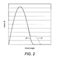
- the cam profile may cause the intake valve to open at about the start of the intake stroke (about 360° crank angle) and to close at about the start of the compression stroke or shortly thereafter (about 540° crank angle or shortly thereafter).
- This first operating profile is shown by the solid line 30 in Figure 2 .
- the first operating profile may be most suitable for medium to heavy engine loading conditions.
- the intake valve may include a variable valve actuation system comprising an intake valve closing mechanism structured and arranged selectively to interrupt cyclical movement of and extend the closing timing of the intake valve to provide a second operating profile for the intake valve.
- closure of the intake valve may be delayed by about 60° crank angle compared to the first operating profile.
- This second operating profile is shown by the dashed line 31 in Figure 2 and represents a LIVC profile.
- the second operating profile may be most suitable for steady-state and/or low engine loading conditions.
- the intake valve closing mechanism may be operated hydraulically, pneumatically, electronically, mechanically, or any combination thereof.
- the intake valve closing mechanism may be selectively operated to supply hydraulic fluid, for example, at a low pressure or a high pressure, in a manner to resist closing of the intake valve by spring-bias. That is, after the intake valve is lifted, i.e., opened, by the cam, and when the cam is no longer holding the intake valve open, the hydraulic fluid may hold the intake valve open for a desired period. The desired period may change depending on the desired performance of the engine.
- a controller 19 may be provided for controlling operation of the internal combustion engine.
- the controller 19 may be operatively connected to the EGR valve 13, the wastegate 15 and the intake valve closing mechanism of each cylinder 11.
- the controller 19 may also be operatively connected to one or more sensors 20 which may provide the controller 19 with indications of one or more engine conditions or other data from which the loading of the internal combustion engine can be determined.
- the sensors 20 may include sensors detecting engine speed, engine torque, or detecting the work state of a vehicle in which the internal combustion engine is incorporated. For example, sensors detecting heavy digging, hill climbing or fast digging may be utilised.
- the operation of the intake valve may be switched from the first operating profile 30 to the second operating profile 31 instantaneously.
- 'instantaneously' is meant that the switching of operation from the first operating profile to the second operating profile is not phased gradually over many engine cycles. Rather, switching may take place between one engine cycle and the next engine cycle, for example within one revolution of a cam shaft of the internal combustion engine.
- the pressure of the intake gas in the intake manifold 18 may be increased at the point, or preferably, prior to switching. This may be achieved by temporarily closing the wastegate 15 to avoid exhaust gases bypassing the turbocharger 14. This results in an increased mass flow of gas through the turbocharger 14 resulting in an increased boost level of the pressurisation of the inlet air fed to the inlet manifold 18.
- Movement of the wastegate may be relatively slow. Therefore, in addition or instead of closing the wastegate 15, the EGR valve 13 may be partially or fully closed prior to switching from the first operating profile 30 to the second operating profile 31 more quickly to increase the quantity of exhaust gas fed to the turbocharger 14. Movement of the EGR valve 13 may be relatively fast compared to movement of the wastegate 15. Closing the EGR valve 13 may also have the effect of increasing the proportion of fresh air entering the cylinders 11.
- Figure 4 is a schematic engine map plotting engine torque versus engine speed of the type which may be suitably incorporated into the programming of the controller 19 to control switching between the first operating profile 30 and the second operating profile 31.
- Region 50 signifies a steady state operating zone where the first operating profile 30 for the intake valve is used.
- Region 51 signifies a steady state operating zone where the second operating profile 31 for the intake valve is used so as to delay closing of the intake valve.
- the regions between boundaries 55 and 56 represent a transitional zone, the effect of which will be described below.
- the engine condition may start in region 50. Under changing engine conditions boundary 56 may first be encountered. At this point the wastegate 15 and/or EGR valve 13 may be closed. As the engine conditions cross a switching boundary 52 the intake valve profile may be instantaneously switched to the second operating profile 31. As the engine conditions cross a debounce boundary 53 the EGR valve 13 may be returned to its prior, open position. However, the wastegate 15 may remain closed. The region between switching boundary 52 and debounce boundary 53 may be used for hysteresis control of the switching process.
- the engine condition may start in region 51.
- boundary 55 may first be encountered.
- the wastegate 15 may start to be opened.
- the intake valve profile may be instantaneously switched to the first operating profile 30 while at the same time the EGR valve 13 may be briefly opened (if not already open) or further opened which may help to reduce any temporary increase in the speed of the turbocharger 14 and temporary increase in the pressure in the intake manifold 18 which might be detrimental to engine components operating near their design limits.
- the wastegate 15 may be opened and control of the EGR valve 13 may return to the steady state control regime for region 50.
- the region between switching boundary 52 and debounce boundary 54 may be used for hysteresis control of the switching process.
- FIG. 3 The beneficial effect of boosting the pressure in the intake manifold 18 prior to switching from the first operating profile 30 to the second operating profile 31 may be seen in Figure 3 .
- the point in time of switching from the first operating profile 30 to the second operating profile 31 is depicted by line 43.
- line 40 indicates the effect of instantaneous switching from the first to the second operating profile without changing the position of the wastegate 15 or EGR valve 13.
- Line 41 indicates the effect of closing the EGR valve 13 and wastegate 15 at the point of switching 43.
- Line 42 indicates the effect of closing the EGR valve 13 and wastegate 15 prior to the point of switching 43.
- Figure 3c shows the wastegate area and illustrates that the wastegate area may be reduced prior to switching for line 42.
- Figure 3e shows the position of the EGR valve 13 and illustrates that the valve may be closed or partially closed prior to the point of switching 43 before being reopened following switching.
- Figure 3d shows the effect of the EGR valve position on the EGR equivalence ratio and illustrates that the ratio decreases before the point of switching 43 before recovering as the EGR valve 13 is reopened.
- FIG 3a shows the effect of altering the operation of the wastegate 15 and EGR valve 13 as described above.
- the graph illustrates that the pressure in the intake manifold 18 increases prior to the point of switching 43 for line 42.
- Figures 3b and 3f show the effect of the increased intake manifold pressure on the air-to-fuel ratio (AFR) and smoke levels respectively. It can be seen that the AFR may undergo a much-reduced dip after the point of switching 43 for line 42 where the intake manifold pressure is increased prior to switching. As shown in Figure 3f this may have the effect of significantly reducing smoke and soot levels - which may be determined using an AVL meter, for example.
- the present disclosure finds application in the design and operation of internal combustion engines and leads to improvements in the control of air-to-fuel ratios when utilising variable valve actuation systems.
Abstract
supplying intake gas from an intake manifold (18) to an air intake port of a combustion chamber in a cylinder (11);
selectively operating an air intake valve using a first operating profile (30) and, on demand, switching selective operation of the air intake valve to a second operating profile (31) in which the closing of the air intake valve is delayed compared to the closing of the air intake valve using the first operating profile;
wherein at the point (43) of or prior to switching from the first operating profile to the second operating profile the pressure of the intake gas in the intake manifold is increased.
Description
- The present disclosure relates to an internal combustion engine and a method of operating an internal combustion engine.
- Internal combustion engines comprise inlet and exhaust valves to control the flow of gases into and out of the combustion chamber of each engine cylinder. Ordinarily the valves are mechanically controlled by means of a camshaft. Profiled cams on the camshaft are used to control timing of opening and closing of each valve.
- Since the physical shape and profile of the cams may only be optimised for one particular operating condition of the internal combustion engine, it is known to use a variable valve actuation system where the operation of the valves may by adjusted to suit changing demand. For example, a standard profile may be utilised during periods of medium or high engine demand and a late inlet valve closing (LIVC) profile may be utilised for the inlet valve during steady state conditions when the demand on the internal combustion engine is relatively low. In a LIVC profile the closing of the intake valve at about the end of the intake stroke is delayed, so that the intake valve remains open for a portion of the compression stroke. This results in a lower pressure within the cylinder. Consequently, the cylinder piston does less work during the compression stroke which leads to improved fuel efficiency.
- A problem with use of an LIVC profile is that when instantaneously switching from the standard profile to the LIVC profile there is a sudden drop in the air-to-fuel ratio within the cylinder. This leads to a rich mixture which tends to produce unwanted soot particulates and smoke. In order to attempt to overcome this problem it is known to employ a control system that gradually switches from the standard profile to the LIVC profile over relatively large number of engine cycles - typically around 20 cycles. However such control systems are complicated and expensive.
- According to the present disclosure there is provided a method of operating an internal combustion engine comprising at least one cylinder, the method comprising:
- supplying intake gas from an intake manifold to an intake port of a combustion chamber in the cylinder;
- selectively operating an intake valve using a first operating profile to open and close the intake port to control flow of the intake gas between the intake manifold and the combustion chamber;
- on demand, switching selective operation of the intake valve to a second operating profile in which the closing of the intake valve is delayed compared to the closing of the intake valve using the first operating profile;
- wherein at the point, or prior to the point of switching from the first operating profile to the second operating profile the pressure of the intake gas in the intake manifold is increased.
- There is also provided an internal combustion engine comprising:
- at least one cylinder;
- an intake manifold for receiving intake gas;
- an intake port communicating between the intake manifold and a combustion chamber of the cylinder;
- an intake valve movable to open and close the intake port to control flow of the intake gas between the intake manifold and the combustion chamber;
- a turbocharger or supercharger for pressurising at least a portion of the intake gas supplied to the intake manifold; and
- a controller configured selectively to control operation of the intake valve between a first operating profile and a second operating profile in which the closing of the intake valve is delayed compared to the closing of the intake valve using the first operating profile;
- the controller being further configured to increase the pressure of the intake gas in the inlet manifold at the point, or prior to the point of switching from the first operating profile to the second operating profile by directly of indirectly controlling operation of the turbocharger or supercharger.
-
-
Figure 1 is a schematic diagram of an internal combustion engine according to the present disclosure; -
Figure 2 is a diagram of intake valve lift versus crank angle; -
Figure 3a is a diagram of inlet manifold air pressure versus time; -
Figure 3b is a diagram of air-to-fuel ratio versus time; -
Figure 3c is a diagram of wastegate area versus time; -
Figure 3d is a diagram of exhaust gas recirculation (EGR) equivalence ratio versus time; -
Figure 3e is a diagram of EGR valve position versus time; -
Figure 3f is a diagram of smoke level versus time; and -
Figure 4 is a schematic engine map plotting engine torque versus engine speed. - The internal combustion engine of the present disclosure, as shown in
Figure 1 , may comprise one ormore cylinders 11 in anengine block 10. For example, the engine may contain four or sixcylinders 11. Anintake manifold 18 may supply intake gas to eachcylinder 11. The intake gas may be a mixture of air and exhaust gases that are recirculated by an exhaust gas recirculation (EGR)system 12. The EGRsystem 12 may comprise a cooler for cooling the recirculated exhaust gases. AnEGR valve 13 may be provided operatively to control the amount of exhaust gas recirculated to theintake manifold 18. - Non-recirculated exhaust gases may be conveyed to an
exhaust line 16 via a turbine section of aturbocharger 14. The exhaust gases may cause the turbine section to rotate thus rotating the compressor section of theturbocharger 14. The compressor section may be configured to pressurise a flow of air supplied to theintake manifold 18 from anair inlet 17. Ambient air may enterair inlet 17. - A
wastegate 15 may be provided to allow exhaust gases to bypass theturbocharger 14. - Each
cylinder 11 may contain a piston slidably movable in thecylinder 11. A crankshaft may be rotatably disposed within the engine. A connecting rod may couple the piston to the crankshaft so that sliding motion of the piston within thecylinder 11 results in rotation of the crankshaft. Similarly, rotation of the crankshaft results in a sliding motion of the piston. For example, an uppermost position of the piston in thecylinder 11 corresponds to a top dead centre position of the crankshaft, and a lowermost position of the piston in thecylinder 11 corresponds to a bottom dead centre position of the crankshaft. - As one skilled in the art will recognize, the piston in a conventional, four-stroke engine cycle reciprocates between the uppermost position and the lowermost position during a combustion (or expansion) stroke, an exhaust stroke, an intake stroke, and a compression stroke. Meanwhile, the crankshaft rotates from the top dead centre position to the bottom dead centre position during the combustion stroke, from the bottom dead centre to the top dead centre during the exhaust stroke, from top dead centre to bottom dead centre during the intake stroke, and from bottom dead centre to top dead centre during the compression stroke. Then, the four-stroke cycle begins again. Each piston stroke correlates to about 180° of crankshaft rotation, or crank angle. Thus, the combustion stroke may begin at about 0° crank angle, the exhaust stroke at about 180°, the intake stroke at about 360°, and the compression stroke at about 540°.
- The
cylinder 11 may include at least one intake port and at least one exhaust port, each opening to a combustion chamber within thecylinder 11. The intake port may be opened and closed by an intake valve, and the exhaust port may be opened and closed by an exhaust valve. The intake valve may be movable between a first, open position in which flow of gas from anintake manifold 18 is permitted to enter the combustion chamber and a second, closed position which substantially blocks flow from theintake manifold 18 into the combustion chamber. The intake valve may be sprung-biased to the second, closed position. - A camshaft carrying a cam with one or more lobes may be arranged to operate the intake valve cyclically based on the configuration of the cam, the lobes, and the rotation of the camshaft to achieve a desired intake valve timing. The exhaust valve may be configured in a manner similar to the intake valve and may be operated by one of the lobes of the cam. Alternatively, the intake valve and/or the exhaust valve may be operated hydraulically, pneumatically, electronically, or by any combination of mechanics, hydraulics, pneumatics, and/or electronics.
- In a first, standard, operating profile of the intake valve, the cam profile may cause the intake valve to open at about the start of the intake stroke (about 360° crank angle) and to close at about the start of the compression stroke or shortly thereafter (about 540° crank angle or shortly thereafter). This first operating profile is shown by the
solid line 30 inFigure 2 . The first operating profile may be most suitable for medium to heavy engine loading conditions. - The intake valve may include a variable valve actuation system comprising an intake valve closing mechanism structured and arranged selectively to interrupt cyclical movement of and extend the closing timing of the intake valve to provide a second operating profile for the intake valve. For example, closure of the intake valve may be delayed by about 60° crank angle compared to the first operating profile. This second operating profile is shown by the dashed
line 31 inFigure 2 and represents a LIVC profile. The second operating profile may be most suitable for steady-state and/or low engine loading conditions. - The intake valve closing mechanism may be operated hydraulically, pneumatically, electronically, mechanically, or any combination thereof. For example, the intake valve closing mechanism may be selectively operated to supply hydraulic fluid, for example, at a low pressure or a high pressure, in a manner to resist closing of the intake valve by spring-bias. That is, after the intake valve is lifted, i.e., opened, by the cam, and when the cam is no longer holding the intake valve open, the hydraulic fluid may hold the intake valve open for a desired period. The desired period may change depending on the desired performance of the engine.
- A
controller 19 may be provided for controlling operation of the internal combustion engine. Thecontroller 19 may be operatively connected to theEGR valve 13, thewastegate 15 and the intake valve closing mechanism of eachcylinder 11. - The
controller 19 may also be operatively connected to one ormore sensors 20 which may provide thecontroller 19 with indications of one or more engine conditions or other data from which the loading of the internal combustion engine can be determined. Thesensors 20 may include sensors detecting engine speed, engine torque, or detecting the work state of a vehicle in which the internal combustion engine is incorporated. For example, sensors detecting heavy digging, hill climbing or fast digging may be utilised. - The operation of the intake valve may be switched from the
first operating profile 30 to thesecond operating profile 31 instantaneously. By 'instantaneously' is meant that the switching of operation from the first operating profile to the second operating profile is not phased gradually over many engine cycles. Rather, switching may take place between one engine cycle and the next engine cycle, for example within one revolution of a cam shaft of the internal combustion engine. - In order to reduce or avoid a drop in the air-to-fuel ratio within the
cylinder 11 when switching from the first operating profile to the second operating profiles, the pressure of the intake gas in theintake manifold 18 may be increased at the point, or preferably, prior to switching. This may be achieved by temporarily closing thewastegate 15 to avoid exhaust gases bypassing theturbocharger 14. This results in an increased mass flow of gas through theturbocharger 14 resulting in an increased boost level of the pressurisation of the inlet air fed to theinlet manifold 18. - Movement of the wastegate may be relatively slow. Therefore, in addition or instead of closing the
wastegate 15, theEGR valve 13 may be partially or fully closed prior to switching from thefirst operating profile 30 to thesecond operating profile 31 more quickly to increase the quantity of exhaust gas fed to theturbocharger 14. Movement of theEGR valve 13 may be relatively fast compared to movement of thewastegate 15. Closing theEGR valve 13 may also have the effect of increasing the proportion of fresh air entering thecylinders 11. -
Figure 4 is a schematic engine map plotting engine torque versus engine speed of the type which may be suitably incorporated into the programming of thecontroller 19 to control switching between thefirst operating profile 30 and thesecond operating profile 31.Region 50 signifies a steady state operating zone where thefirst operating profile 30 for the intake valve is used.Region 51 signifies a steady state operating zone where thesecond operating profile 31 for the intake valve is used so as to delay closing of the intake valve. The regions betweenboundaries - A non-limiting example of switching from the
first operating profile 30 to thesecond operating profile 31 will now be described. The engine condition may start inregion 50. Under changingengine conditions boundary 56 may first be encountered. At this point thewastegate 15 and/orEGR valve 13 may be closed. As the engine conditions cross a switchingboundary 52 the intake valve profile may be instantaneously switched to thesecond operating profile 31. As the engine conditions cross adebounce boundary 53 theEGR valve 13 may be returned to its prior, open position. However, thewastegate 15 may remain closed. The region between switchingboundary 52 anddebounce boundary 53 may be used for hysteresis control of the switching process. - A non-limiting example of switching from the
second operating profile 31 to thefirst operating profile 30 will now be described where the engine may be under high speed, high load conditions such that the engine components may be operating near their design limits. The engine condition may start inregion 51. Under changing engine conditions, for example during a transient loading event,boundary 55 may first be encountered. At this point thewastegate 15 may start to be opened. As the engine conditions cross the switchingboundary 52 the intake valve profile may be instantaneously switched to thefirst operating profile 30 while at the same time theEGR valve 13 may be briefly opened (if not already open) or further opened which may help to reduce any temporary increase in the speed of theturbocharger 14 and temporary increase in the pressure in theintake manifold 18 which might be detrimental to engine components operating near their design limits. As the engine conditions cross adebounce boundary 54 thewastegate 15 may be opened and control of theEGR valve 13 may return to the steady state control regime forregion 50. The region between switchingboundary 52 anddebounce boundary 54 may be used for hysteresis control of the switching process. - The beneficial effect of boosting the pressure in the
intake manifold 18 prior to switching from thefirst operating profile 30 to thesecond operating profile 31 may be seen inFigure 3 . InFigure 3 the point in time of switching from thefirst operating profile 30 to thesecond operating profile 31 is depicted byline 43. In each ofFigures 3a to 3f ,line 40 indicates the effect of instantaneous switching from the first to the second operating profile without changing the position of thewastegate 15 orEGR valve 13.Line 41 indicates the effect of closing theEGR valve 13 andwastegate 15 at the point of switching 43.Line 42 indicates the effect of closing theEGR valve 13 andwastegate 15 prior to the point of switching 43. -
Figure 3c shows the wastegate area and illustrates that the wastegate area may be reduced prior to switching forline 42. -
Figure 3e shows the position of theEGR valve 13 and illustrates that the valve may be closed or partially closed prior to the point of switching 43 before being reopened following switching. -
Figure 3d shows the effect of the EGR valve position on the EGR equivalence ratio and illustrates that the ratio decreases before the point of switching 43 before recovering as theEGR valve 13 is reopened. -
Figure 3a shows the effect of altering the operation of thewastegate 15 andEGR valve 13 as described above. In particular the graph illustrates that the pressure in theintake manifold 18 increases prior to the point of switching 43 forline 42. -
Figures 3b and 3f show the effect of the increased intake manifold pressure on the air-to-fuel ratio (AFR) and smoke levels respectively. It can be seen that the AFR may undergo a much-reduced dip after the point of switching 43 forline 42 where the intake manifold pressure is increased prior to switching. As shown inFigure 3f this may have the effect of significantly reducing smoke and soot levels - which may be determined using an AVL meter, for example. - It can therefore be seen that whilst closing the
EGR valve 13 andwastegate 15 at the point of switching 43 (line 41) may have some beneficial effect, the most beneficial effect may be achieved by closing theEGR valve 13 andwastegate 15 prior to the point of switching 43 (line 42). - The present disclosure finds application in the design and operation of internal combustion engines and leads to improvements in the control of air-to-fuel ratios when utilising variable valve actuation systems.
-
- 10
- Engine block
- 11
- Cylinder
- 12
- EGR system
- 13
- EGR valve
- 14
- Turbocharger
- 15
- Wastegate
- 16
- Exhaust line
- 17
- Air inlet
- 18
- Inlet manifold
- 19
- Controller
- 20
- Sensor(s)
- 30
- First operating profile
- 31
- Second operating profile
- 40
- Switching from the first to the second operating profile without changing the position of the
wastegate 15 orEGR valve 13 - 41
- Switching from the first to the second operating profile and closing the
EGR valve 13 andwastegate 15 at the point of switching - 42
- Switching from the first to the second operating profile and closing the
EGR valve 13 andwastegate 15 prior to the point of switching - 43
- Point of switching
- 50
- Steady state region for first operating profile
- 51
- Steady state region for second operating profile
- 52
- Switching boundary
- 53
- Debounce boundary
- 54
- Debounce boundary
- 55
- Transitional zone boundary
- 56
- Transitional zone boundary
Claims (15)
- A method of operating an internal combustion engine comprising at least one cylinder (11), the method comprising:supplying intake gas from an intake manifold (18) to an intake port of a combustion chamber in the cylinder (11);selectively operating an intake valve using a first operating profile (30) to open and close the intake port to control flow of the intake gas between the intake manifold (18) and the combustion chamber;on demand, switching selective operation of the intake valve to a second operating profile (31) in which the closing of the intake valve is delayed compared to the closing of the intake valve using the first operating profile (30);wherein at the point (43), or prior to the point of switching from the first operating profile (30) to the second operating profile (31) the pressure of the intake gas in the intake manifold (18) is increased.
- The method of claim 1 wherein the pressure of the intake gas in the intake manifold (18) is increased prior to the point of switching (43) from the first operating profile (30) to the second operating profile (31).
- The method of claim 1 or claim 2 wherein closing of the intake valve is delayed for a portion or a whole of a first half of a compression stroke.
- The method of any preceding claim wherein switching between the first operating profile (30) and the second operating profile (31) is based on at least one engine condition.
- The method of any preceding claim wherein switching between the first operating profile (30) and the second operating profile (31) is instantaneous.
- The method of any preceding claim wherein at least a portion of the intake gas is supplied from a turbocharger (14) or supercharger and the pressure of the intake gas in the intake manifold (18) is increased by selective operation of the turbocharger (14) or supercharger.
- The method of claim 6 wherein selective operation of the turbocharger (14) includes selectively operating a wastegate (15) to increase the mass flow of exhaust gas through the turbocharger (14).
- The method of claim 6 or claim 7 wherein the intake gas comprises a mixture of air and recirculated exhaust gas supplied from an exhaust gas recirculation (EGR) system (12) .
- The method of claim 8 comprising selectively operating a valve (13) of the EGR system (12) to increase the mass flow of exhaust gas through the turbocharger (14).
- The method of claim 9 wherein selectively operating the valve (13) of the EGR system (12) includes closing or partially closing the valve (13) prior to switching from the first operating profile (30) to the second operating profile (31).
- An internal combustion engine comprising:at least one cylinder (11);an intake manifold (18) for receiving intake gas;an intake port communicating between the intake manifold (18) and a combustion chamber of the cylinder (11);an intake valve movable to open and close the intake port to control flow of the intake gas between the intake manifold (18) and the combustion chamber;a turbocharger (14) or supercharger for pressurising at least a portion of the intake gas supplied to the intake manifold (18); anda controller (19) configured selectively to control operation of the intake valve between a first operating profile (30) and a second operating profile (31) in which the closing of the intake valve is delayed compared to the closing of the intake valve using the first operating profile (30);the controller (19) being further configured to increase the pressure of the intake gas in the inlet manifold (18) at the point (43), or prior to the point of switching from the first operating profile (30) to the second operating profile (31) by directly of indirectly controlling operation of the turbocharger (14) or supercharger.
- The internal combustion engine of claim 11 wherein the controller (19) is configured to increase the pressure of the intake gas in the inlet manifold (18) prior to the point of switching (43) from the first operating profile (30) to the second operating profile (31).
- The internal combustion engine of claim 11 or claim 12 further comprising one or more sensors (20) for detecting a load state of the internal combustion engine; the controller (19) being configured to switch between the first operating profile (30) and the second operating profile (31) dependent on output of the one or more sensors (20).
- The internal combustion engine of any of claims 11 to 13 wherein the turbocharger (14) comprises a wastegate (15) and the controller (19) is configured to control operation of the turbocharger (14) by at least partially closing the wastegate (15) prior to switching to the second operating profile (31).
- The internal combustion engine of any of claims 11 to 14 further comprising an exhaust gas recirculation (EGR) system (12) and wherein the controller (19) is configured to control operation of the turbocharger (14) by at least partially closing a valve (13) of the EGR system (12) prior to switching to the second operating profile (31).
Priority Applications (4)
| Application Number | Priority Date | Filing Date | Title |
|---|---|---|---|
| EP10195627.4A EP2466098B1 (en) | 2010-12-17 | 2010-12-17 | An Internal Combustion Engine and a Method of Operation of an Internal Combustion Engine |
| CN2011800600683A CN103328788A (en) | 2010-12-17 | 2011-12-06 | An internal combustion engine and a method of operation of an internal combustion engine |
| US13/989,739 US9163559B2 (en) | 2010-12-17 | 2011-12-06 | Internal combustion engine and a method of operation of an internal combustion engine |
| PCT/EP2011/071959 WO2012080043A1 (en) | 2010-12-17 | 2011-12-06 | An internal combustion engine and a method of operation of an internal combustion engine |
Applications Claiming Priority (1)
| Application Number | Priority Date | Filing Date | Title |
|---|---|---|---|
| EP10195627.4A EP2466098B1 (en) | 2010-12-17 | 2010-12-17 | An Internal Combustion Engine and a Method of Operation of an Internal Combustion Engine |
Publications (2)
| Publication Number | Publication Date |
|---|---|
| EP2466098A1 true EP2466098A1 (en) | 2012-06-20 |
| EP2466098B1 EP2466098B1 (en) | 2013-09-25 |
Family
ID=43903995
Family Applications (1)
| Application Number | Title | Priority Date | Filing Date |
|---|---|---|---|
| EP10195627.4A Not-in-force EP2466098B1 (en) | 2010-12-17 | 2010-12-17 | An Internal Combustion Engine and a Method of Operation of an Internal Combustion Engine |
Country Status (4)
| Country | Link |
|---|---|
| US (1) | US9163559B2 (en) |
| EP (1) | EP2466098B1 (en) |
| CN (1) | CN103328788A (en) |
| WO (1) | WO2012080043A1 (en) |
Cited By (1)
| Publication number | Priority date | Publication date | Assignee | Title |
|---|---|---|---|---|
| CN110778400A (en) * | 2018-07-24 | 2020-02-11 | 大众汽车有限公司 | Method for controlling and/or regulating the operation of an internal combustion engine |
Families Citing this family (3)
| Publication number | Priority date | Publication date | Assignee | Title |
|---|---|---|---|---|
| US9068522B2 (en) * | 2012-04-27 | 2015-06-30 | Ford Global Technologies, Llc | Method for diagnosing an engine |
| US9546612B2 (en) | 2014-06-04 | 2017-01-17 | Caterpillar Inc. | Control method for an engine with exhaust gas recirculation and intake valve actuation |
| GB2545203A (en) * | 2015-12-08 | 2017-06-14 | Gm Global Tech Operations Llc | A method of operating an automotive system for powering a vehicle |
Citations (5)
| Publication number | Priority date | Publication date | Assignee | Title |
|---|---|---|---|---|
| JPH0436026A (en) * | 1990-05-22 | 1992-02-06 | Mazda Motor Corp | Intake system of engine |
| JPH06330776A (en) * | 1993-05-19 | 1994-11-29 | Mazda Motor Corp | Intake device for engine with mechanical supercharger |
| JPH07102982A (en) * | 1993-09-30 | 1995-04-18 | Mazda Motor Corp | Engine having supercharger |
| US5778674A (en) * | 1995-04-25 | 1998-07-14 | Nissan Motor Co., Ltd. | Turbocharged diesel engine |
| US20040006986A1 (en) * | 2002-06-07 | 2004-01-15 | Michael Baeuerle | Method and arrangement for controlling an internal combustion engine |
Family Cites Families (17)
| Publication number | Priority date | Publication date | Assignee | Title |
|---|---|---|---|---|
| US5161497A (en) | 1992-03-11 | 1992-11-10 | Ford Motor Company | Variable valve timing operated engine |
| JP3422033B2 (en) * | 1992-09-28 | 2003-06-30 | マツダ株式会社 | Intake device for engine with mechanical supercharger |
| GB2301398B (en) | 1994-03-07 | 1998-01-14 | Komatsu Mfg Co Ltd | Variable compression ratio engine |
| US5642703A (en) * | 1995-10-16 | 1997-07-01 | Ford Motor Company | Internal combustion engine with intake and exhaust camshaft phase shifting for cylinder deactivation |
| JP3879227B2 (en) | 1998-02-06 | 2007-02-07 | 日産自動車株式会社 | Mirror cycle engine intake / exhaust valve control system |
| EP0983433B1 (en) | 1998-02-23 | 2007-05-16 | Cummins Inc. | Premixed charge compression ignition engine with optimal combustion control |
| US6321731B1 (en) | 2000-01-19 | 2001-11-27 | Ford Global Technologies, Inc. | Engine control strategy using dual equal cam phasing combined with exhaust gas recirculation |
| JP2002201998A (en) * | 2000-11-06 | 2002-07-19 | Denso Corp | Controller of internal combustion engine |
| DE10222703B4 (en) * | 2001-05-23 | 2015-06-18 | Denso Corporation | Control unit for an internal combustion engine |
| JP3997477B2 (en) * | 2001-10-05 | 2007-10-24 | 株式会社デンソー | Control device for internal combustion engine |
| US6651618B1 (en) | 2002-05-14 | 2003-11-25 | Caterpillar Inc | Air and fuel supply system for combustion engine |
| US6964270B2 (en) | 2003-08-08 | 2005-11-15 | Cummins, Inc. | Dual mode EGR valve |
| US7184877B1 (en) * | 2005-09-29 | 2007-02-27 | International Engine Intellectual Property Company, Llc | Model-based controller for auto-ignition optimization in a diesel engine |
| US7275516B1 (en) * | 2006-03-20 | 2007-10-02 | Ford Global Technologies, Llc | System and method for boosted direct injection engine |
| US20070261406A1 (en) | 2006-05-12 | 2007-11-15 | General Electric Company | Systems and methods of reducing NOx emissions in internal combustion engines |
| DE102006032719A1 (en) | 2006-07-14 | 2008-01-17 | Daimler Ag | Method for operating an Otto engine |
| JP4804384B2 (en) * | 2007-03-08 | 2011-11-02 | 日立オートモティブシステムズ株式会社 | Variable valve operating device and control device for internal combustion engine |
-
2010
- 2010-12-17 EP EP10195627.4A patent/EP2466098B1/en not_active Not-in-force
-
2011
- 2011-12-06 WO PCT/EP2011/071959 patent/WO2012080043A1/en active Application Filing
- 2011-12-06 US US13/989,739 patent/US9163559B2/en active Active
- 2011-12-06 CN CN2011800600683A patent/CN103328788A/en active Pending
Patent Citations (5)
| Publication number | Priority date | Publication date | Assignee | Title |
|---|---|---|---|---|
| JPH0436026A (en) * | 1990-05-22 | 1992-02-06 | Mazda Motor Corp | Intake system of engine |
| JPH06330776A (en) * | 1993-05-19 | 1994-11-29 | Mazda Motor Corp | Intake device for engine with mechanical supercharger |
| JPH07102982A (en) * | 1993-09-30 | 1995-04-18 | Mazda Motor Corp | Engine having supercharger |
| US5778674A (en) * | 1995-04-25 | 1998-07-14 | Nissan Motor Co., Ltd. | Turbocharged diesel engine |
| US20040006986A1 (en) * | 2002-06-07 | 2004-01-15 | Michael Baeuerle | Method and arrangement for controlling an internal combustion engine |
Cited By (1)
| Publication number | Priority date | Publication date | Assignee | Title |
|---|---|---|---|---|
| CN110778400A (en) * | 2018-07-24 | 2020-02-11 | 大众汽车有限公司 | Method for controlling and/or regulating the operation of an internal combustion engine |
Also Published As
| Publication number | Publication date |
|---|---|
| US9163559B2 (en) | 2015-10-20 |
| WO2012080043A1 (en) | 2012-06-21 |
| EP2466098B1 (en) | 2013-09-25 |
| US20130247564A1 (en) | 2013-09-26 |
| CN103328788A (en) | 2013-09-25 |
Similar Documents
| Publication | Publication Date | Title |
|---|---|---|
| CN101749121B (en) | Engine intake quantity control apparatus | |
| CN101849091B (en) | Internal combustion engine controller | |
| CN101466933B (en) | Spark ignition type internal combustion engine | |
| US7100547B2 (en) | Intake-air control system for engine | |
| US8448616B2 (en) | Internal combustion engine cycle | |
| CN103328775B (en) | There is quartastroke engine and the method for VVT | |
| JP2009002283A (en) | Control system of internal combustion engine | |
| CN1298981C (en) | Control strategy for turbocharged engine having variable valve actuation apparatus | |
| JP2011149428A (en) | Residual combustion gas scavenging method in direct-injection supercharged internal-combustion multi-cylinder engine running under partial load | |
| JP2013530329A (en) | Engine control device | |
| JP4893514B2 (en) | Control device for an internal combustion engine with a supercharger | |
| US9163559B2 (en) | Internal combustion engine and a method of operation of an internal combustion engine | |
| CN111788378B (en) | Internal combustion engine and control method thereof | |
| SE531208C2 (en) | Method for controlling the recirculation of the exhaust gases of a combustion engine with a charge compressor and an engine using such method | |
| US10060361B2 (en) | Method for performing a charge exchange in an internal combustion engine | |
| EP2698518B1 (en) | Internal combustion engine control apparatus | |
| JP6544363B2 (en) | Control device for internal combustion engine | |
| JP2009299623A (en) | Control device for internal combustion engine | |
| JP2014214638A (en) | Engine device with turbo supercharger | |
| CN112400055A (en) | Method for operating an internal combustion engine, in particular of a motor vehicle, in an engine braking operation | |
| CN201496115U (en) | Continuous variable gas distribution control system of spark ignition engine | |
| CN201496116U (en) | Continuous variable valve gas-distributing control system of compression ignition engines | |
| CN116324147A (en) | Method for operating an internal combustion engine, in particular of a motor vehicle, and internal combustion engine | |
| KR20200120806A (en) | 2 cycle engine with valve system | |
| JP2011236824A (en) | Device for control of internal combustion engine |
Legal Events
| Date | Code | Title | Description |
|---|---|---|---|
| PUAI | Public reference made under article 153(3) epc to a published international application that has entered the european phase |
Free format text: ORIGINAL CODE: 0009012 |
|
| AK | Designated contracting states |
Kind code of ref document: A1 Designated state(s): AL AT BE BG CH CY CZ DE DK EE ES FI FR GB GR HR HU IE IS IT LI LT LU LV MC MK MT NL NO PL PT RO RS SE SI SK SM TR |
|
| AX | Request for extension of the european patent |
Extension state: BA ME |
|
| 17P | Request for examination filed |
Effective date: 20121219 |
|
| GRAP | Despatch of communication of intention to grant a patent |
Free format text: ORIGINAL CODE: EPIDOSNIGR1 |
|
| INTG | Intention to grant announced |
Effective date: 20130419 |
|
| GRAS | Grant fee paid |
Free format text: ORIGINAL CODE: EPIDOSNIGR3 |
|
| GRAA | (expected) grant |
Free format text: ORIGINAL CODE: 0009210 |
|
| AK | Designated contracting states |
Kind code of ref document: B1 Designated state(s): AL AT BE BG CH CY CZ DE DK EE ES FI FR GB GR HR HU IE IS IT LI LT LU LV MC MK MT NL NO PL PT RO RS SE SI SK SM TR |
|
| REG | Reference to a national code |
Ref country code: GB Ref legal event code: FG4D |
|
| REG | Reference to a national code |
Ref country code: CH Ref legal event code: EP |
|
| REG | Reference to a national code |
Ref country code: AT Ref legal event code: REF Ref document number: 633805 Country of ref document: AT Kind code of ref document: T Effective date: 20131015 |
|
| REG | Reference to a national code |
Ref country code: IE Ref legal event code: FG4D |
|
| REG | Reference to a national code |
Ref country code: DE Ref legal event code: R096 Ref document number: 602010010508 Country of ref document: DE Effective date: 20131121 |
|
| PG25 | Lapsed in a contracting state [announced via postgrant information from national office to epo] |
Ref country code: SE Free format text: LAPSE BECAUSE OF FAILURE TO SUBMIT A TRANSLATION OF THE DESCRIPTION OR TO PAY THE FEE WITHIN THE PRESCRIBED TIME-LIMIT Effective date: 20130925 Ref country code: NO Free format text: LAPSE BECAUSE OF FAILURE TO SUBMIT A TRANSLATION OF THE DESCRIPTION OR TO PAY THE FEE WITHIN THE PRESCRIBED TIME-LIMIT Effective date: 20131225 Ref country code: HR Free format text: LAPSE BECAUSE OF FAILURE TO SUBMIT A TRANSLATION OF THE DESCRIPTION OR TO PAY THE FEE WITHIN THE PRESCRIBED TIME-LIMIT Effective date: 20130925 Ref country code: LT Free format text: LAPSE BECAUSE OF FAILURE TO SUBMIT A TRANSLATION OF THE DESCRIPTION OR TO PAY THE FEE WITHIN THE PRESCRIBED TIME-LIMIT Effective date: 20130925 |
|
| REG | Reference to a national code |
Ref country code: AT Ref legal event code: MK05 Ref document number: 633805 Country of ref document: AT Kind code of ref document: T Effective date: 20130925 |
|
| REG | Reference to a national code |
Ref country code: NL Ref legal event code: VDEP Effective date: 20130925 |
|
| REG | Reference to a national code |
Ref country code: LT Ref legal event code: MG4D |
|
| PG25 | Lapsed in a contracting state [announced via postgrant information from national office to epo] |
Ref country code: GR Free format text: LAPSE BECAUSE OF FAILURE TO SUBMIT A TRANSLATION OF THE DESCRIPTION OR TO PAY THE FEE WITHIN THE PRESCRIBED TIME-LIMIT Effective date: 20131226 Ref country code: RS Free format text: LAPSE BECAUSE OF FAILURE TO SUBMIT A TRANSLATION OF THE DESCRIPTION OR TO PAY THE FEE WITHIN THE PRESCRIBED TIME-LIMIT Effective date: 20130925 Ref country code: FI Free format text: LAPSE BECAUSE OF FAILURE TO SUBMIT A TRANSLATION OF THE DESCRIPTION OR TO PAY THE FEE WITHIN THE PRESCRIBED TIME-LIMIT Effective date: 20130925 Ref country code: LV Free format text: LAPSE BECAUSE OF FAILURE TO SUBMIT A TRANSLATION OF THE DESCRIPTION OR TO PAY THE FEE WITHIN THE PRESCRIBED TIME-LIMIT Effective date: 20130925 Ref country code: SI Free format text: LAPSE BECAUSE OF FAILURE TO SUBMIT A TRANSLATION OF THE DESCRIPTION OR TO PAY THE FEE WITHIN THE PRESCRIBED TIME-LIMIT Effective date: 20130925 |
|
| PG25 | Lapsed in a contracting state [announced via postgrant information from national office to epo] |
Ref country code: BE Free format text: LAPSE BECAUSE OF FAILURE TO SUBMIT A TRANSLATION OF THE DESCRIPTION OR TO PAY THE FEE WITHIN THE PRESCRIBED TIME-LIMIT Effective date: 20130925 |
|
| PG25 | Lapsed in a contracting state [announced via postgrant information from national office to epo] |
Ref country code: IS Free format text: LAPSE BECAUSE OF FAILURE TO SUBMIT A TRANSLATION OF THE DESCRIPTION OR TO PAY THE FEE WITHIN THE PRESCRIBED TIME-LIMIT Effective date: 20140125 Ref country code: EE Free format text: LAPSE BECAUSE OF FAILURE TO SUBMIT A TRANSLATION OF THE DESCRIPTION OR TO PAY THE FEE WITHIN THE PRESCRIBED TIME-LIMIT Effective date: 20130925 Ref country code: RO Free format text: LAPSE BECAUSE OF FAILURE TO SUBMIT A TRANSLATION OF THE DESCRIPTION OR TO PAY THE FEE WITHIN THE PRESCRIBED TIME-LIMIT Effective date: 20130925 Ref country code: CZ Free format text: LAPSE BECAUSE OF FAILURE TO SUBMIT A TRANSLATION OF THE DESCRIPTION OR TO PAY THE FEE WITHIN THE PRESCRIBED TIME-LIMIT Effective date: 20130925 Ref country code: NL Free format text: LAPSE BECAUSE OF FAILURE TO SUBMIT A TRANSLATION OF THE DESCRIPTION OR TO PAY THE FEE WITHIN THE PRESCRIBED TIME-LIMIT Effective date: 20130925 Ref country code: SK Free format text: LAPSE BECAUSE OF FAILURE TO SUBMIT A TRANSLATION OF THE DESCRIPTION OR TO PAY THE FEE WITHIN THE PRESCRIBED TIME-LIMIT Effective date: 20130925 |
|
| PG25 | Lapsed in a contracting state [announced via postgrant information from national office to epo] |
Ref country code: PL Free format text: LAPSE BECAUSE OF FAILURE TO SUBMIT A TRANSLATION OF THE DESCRIPTION OR TO PAY THE FEE WITHIN THE PRESCRIBED TIME-LIMIT Effective date: 20130925 Ref country code: CY Free format text: LAPSE BECAUSE OF FAILURE TO SUBMIT A TRANSLATION OF THE DESCRIPTION OR TO PAY THE FEE WITHIN THE PRESCRIBED TIME-LIMIT Effective date: 20130925 Ref country code: ES Free format text: LAPSE BECAUSE OF FAILURE TO SUBMIT A TRANSLATION OF THE DESCRIPTION OR TO PAY THE FEE WITHIN THE PRESCRIBED TIME-LIMIT Effective date: 20130925 Ref country code: AT Free format text: LAPSE BECAUSE OF FAILURE TO SUBMIT A TRANSLATION OF THE DESCRIPTION OR TO PAY THE FEE WITHIN THE PRESCRIBED TIME-LIMIT Effective date: 20130925 |
|
| REG | Reference to a national code |
Ref country code: DE Ref legal event code: R097 Ref document number: 602010010508 Country of ref document: DE |
|
| PG25 | Lapsed in a contracting state [announced via postgrant information from national office to epo] |
Ref country code: PT Free format text: LAPSE BECAUSE OF FAILURE TO SUBMIT A TRANSLATION OF THE DESCRIPTION OR TO PAY THE FEE WITHIN THE PRESCRIBED TIME-LIMIT Effective date: 20140127 |
|
| PLBE | No opposition filed within time limit |
Free format text: ORIGINAL CODE: 0009261 |
|
| STAA | Information on the status of an ep patent application or granted ep patent |
Free format text: STATUS: NO OPPOSITION FILED WITHIN TIME LIMIT |
|
| PG25 | Lapsed in a contracting state [announced via postgrant information from national office to epo] |
Ref country code: LU Free format text: LAPSE BECAUSE OF FAILURE TO SUBMIT A TRANSLATION OF THE DESCRIPTION OR TO PAY THE FEE WITHIN THE PRESCRIBED TIME-LIMIT Effective date: 20131217 Ref country code: IT Free format text: LAPSE BECAUSE OF FAILURE TO SUBMIT A TRANSLATION OF THE DESCRIPTION OR TO PAY THE FEE WITHIN THE PRESCRIBED TIME-LIMIT Effective date: 20130925 |
|
| 26N | No opposition filed |
Effective date: 20140626 |
|
| REG | Reference to a national code |
Ref country code: IE Ref legal event code: MM4A |
|
| REG | Reference to a national code |
Ref country code: FR Ref legal event code: ST Effective date: 20140829 |
|
| PG25 | Lapsed in a contracting state [announced via postgrant information from national office to epo] |
Ref country code: DK Free format text: LAPSE BECAUSE OF FAILURE TO SUBMIT A TRANSLATION OF THE DESCRIPTION OR TO PAY THE FEE WITHIN THE PRESCRIBED TIME-LIMIT Effective date: 20130925 |
|
| REG | Reference to a national code |
Ref country code: DE Ref legal event code: R097 Ref document number: 602010010508 Country of ref document: DE Effective date: 20140626 |
|
| PG25 | Lapsed in a contracting state [announced via postgrant information from national office to epo] |
Ref country code: IE Free format text: LAPSE BECAUSE OF NON-PAYMENT OF DUE FEES Effective date: 20131217 |
|
| PG25 | Lapsed in a contracting state [announced via postgrant information from national office to epo] |
Ref country code: FR Free format text: LAPSE BECAUSE OF NON-PAYMENT OF DUE FEES Effective date: 20131231 |
|
| PG25 | Lapsed in a contracting state [announced via postgrant information from national office to epo] |
Ref country code: MC Free format text: LAPSE BECAUSE OF FAILURE TO SUBMIT A TRANSLATION OF THE DESCRIPTION OR TO PAY THE FEE WITHIN THE PRESCRIBED TIME-LIMIT Effective date: 20130925 |
|
| PG25 | Lapsed in a contracting state [announced via postgrant information from national office to epo] |
Ref country code: SM Free format text: LAPSE BECAUSE OF FAILURE TO SUBMIT A TRANSLATION OF THE DESCRIPTION OR TO PAY THE FEE WITHIN THE PRESCRIBED TIME-LIMIT Effective date: 20130925 |
|
| PG25 | Lapsed in a contracting state [announced via postgrant information from national office to epo] |
Ref country code: TR Free format text: LAPSE BECAUSE OF FAILURE TO SUBMIT A TRANSLATION OF THE DESCRIPTION OR TO PAY THE FEE WITHIN THE PRESCRIBED TIME-LIMIT Effective date: 20130925 |
|
| PG25 | Lapsed in a contracting state [announced via postgrant information from national office to epo] |
Ref country code: BG Free format text: LAPSE BECAUSE OF FAILURE TO SUBMIT A TRANSLATION OF THE DESCRIPTION OR TO PAY THE FEE WITHIN THE PRESCRIBED TIME-LIMIT Effective date: 20130925 Ref country code: HU Free format text: LAPSE BECAUSE OF FAILURE TO SUBMIT A TRANSLATION OF THE DESCRIPTION OR TO PAY THE FEE WITHIN THE PRESCRIBED TIME-LIMIT; INVALID AB INITIO Effective date: 20101217 Ref country code: MK Free format text: LAPSE BECAUSE OF FAILURE TO SUBMIT A TRANSLATION OF THE DESCRIPTION OR TO PAY THE FEE WITHIN THE PRESCRIBED TIME-LIMIT Effective date: 20130925 |
|
| REG | Reference to a national code |
Ref country code: CH Ref legal event code: PL |
|
| PG25 | Lapsed in a contracting state [announced via postgrant information from national office to epo] |
Ref country code: MT Free format text: LAPSE BECAUSE OF FAILURE TO SUBMIT A TRANSLATION OF THE DESCRIPTION OR TO PAY THE FEE WITHIN THE PRESCRIBED TIME-LIMIT Effective date: 20130925 |
|
| PG25 | Lapsed in a contracting state [announced via postgrant information from national office to epo] |
Ref country code: CH Free format text: LAPSE BECAUSE OF NON-PAYMENT OF DUE FEES Effective date: 20141231 Ref country code: LI Free format text: LAPSE BECAUSE OF NON-PAYMENT OF DUE FEES Effective date: 20141231 |
|
| PG25 | Lapsed in a contracting state [announced via postgrant information from national office to epo] |
Ref country code: AL Free format text: LAPSE BECAUSE OF FAILURE TO SUBMIT A TRANSLATION OF THE DESCRIPTION OR TO PAY THE FEE WITHIN THE PRESCRIBED TIME-LIMIT Effective date: 20130925 |
|
| PGFP | Annual fee paid to national office [announced via postgrant information from national office to epo] |
Ref country code: GB Payment date: 20211118 Year of fee payment: 12 Ref country code: DE Payment date: 20211117 Year of fee payment: 12 |
|
| REG | Reference to a national code |
Ref country code: DE Ref legal event code: R119 Ref document number: 602010010508 Country of ref document: DE |
|
| GBPC | Gb: european patent ceased through non-payment of renewal fee |
Effective date: 20221217 |
|
| PG25 | Lapsed in a contracting state [announced via postgrant information from national office to epo] |
Ref country code: GB Free format text: LAPSE BECAUSE OF NON-PAYMENT OF DUE FEES Effective date: 20221217 Ref country code: DE Free format text: LAPSE BECAUSE OF NON-PAYMENT OF DUE FEES Effective date: 20230701 |