EP2466085A2 - Centrifugal, wet-type air cleaner - Google Patents
Centrifugal, wet-type air cleaner Download PDFInfo
- Publication number
- EP2466085A2 EP2466085A2 EP10808319A EP10808319A EP2466085A2 EP 2466085 A2 EP2466085 A2 EP 2466085A2 EP 10808319 A EP10808319 A EP 10808319A EP 10808319 A EP10808319 A EP 10808319A EP 2466085 A2 EP2466085 A2 EP 2466085A2
- Authority
- EP
- European Patent Office
- Prior art keywords
- water
- centrifugal
- air
- air cleaner
- type air
- Prior art date
- Legal status (The legal status is an assumption and is not a legal conclusion. Google has not performed a legal analysis and makes no representation as to the accuracy of the status listed.)
- Withdrawn
Links
Images


Classifications
-
- B—PERFORMING OPERATIONS; TRANSPORTING
- B01—PHYSICAL OR CHEMICAL PROCESSES OR APPARATUS IN GENERAL
- B01D—SEPARATION
- B01D45/00—Separating dispersed particles from gases or vapours by gravity, inertia, or centrifugal forces
- B01D45/12—Separating dispersed particles from gases or vapours by gravity, inertia, or centrifugal forces by centrifugal forces
- B01D45/14—Separating dispersed particles from gases or vapours by gravity, inertia, or centrifugal forces by centrifugal forces generated by rotating vanes, discs, drums or brushes
-
- F—MECHANICAL ENGINEERING; LIGHTING; HEATING; WEAPONS; BLASTING
- F24—HEATING; RANGES; VENTILATING
- F24F—AIR-CONDITIONING; AIR-HUMIDIFICATION; VENTILATION; USE OF AIR CURRENTS FOR SCREENING
- F24F3/00—Air-conditioning systems in which conditioned primary air is supplied from one or more central stations to distributing units in the rooms or spaces where it may receive secondary treatment; Apparatus specially designed for such systems
- F24F3/12—Air-conditioning systems in which conditioned primary air is supplied from one or more central stations to distributing units in the rooms or spaces where it may receive secondary treatment; Apparatus specially designed for such systems characterised by the treatment of the air otherwise than by heating and cooling
- F24F3/16—Air-conditioning systems in which conditioned primary air is supplied from one or more central stations to distributing units in the rooms or spaces where it may receive secondary treatment; Apparatus specially designed for such systems characterised by the treatment of the air otherwise than by heating and cooling by purification, e.g. by filtering; by sterilisation; by ozonisation
Definitions
- This invention relates to a wet type air cleaner utilizing a centrifugal impeller for fresh air, thus firstly airborne fine particulate dust, noxious gases and odor particles, pathogens, and the number of cleaning bacteria trapped using the water droplets in the scrubbing room, and secondarily the pollutant water is centrifugally separated from air on the basis of the difference between the specific gravity of gases and liquids (approximately1:1000) with using high-speed rotating centrifugal impeller with a powerful strength of the centrifugal force causes the vortex structure in the base to cleanse the air or gas, since scrubbing the pollution material including dust, harmful gaseous substances, virus and bacteria in air with the positive three dimensional vortex stream of water droplets, mist and fog on the basis of natural water instead of using solid filters with utilizing a depressing room on the outlet of a body.
- This invention relates to a wet type air cleaner utilizing a centrifugal impeller for fresh air, thus the separation of pollution substances with scrubbing liquid can be absolutely eliminated from air with utilizing the difference of specific gravity (approximately 1:1000) between air and liquid by the strength of centrifugal force in the vortex generating structure such as centrifugal impeller, since scrubbing the pollution material including dust, harmful gaseous substances, virus and bacteria in air with the positive three dimensional vortex stream of fine water droplets, mist and fog on the basis of natural water instead of using solid filters with utilizing a depression room on the outlet of a body.
- the air include bacteria, pathogens, sand and toxic gases, smoke, dust, oil, water, tire dust, pollen and a fine dust sizing smaller than 0,1 ⁇ m, the smell particles are a mixture of pollutants.
- the invention primarily airborne fine particulate dust, noxious gases and odor particles, pathogens, and bacteria by washing water collected in the wet air with lot of water droplets, and secondarily the wet air can be purged with high efficiency on the basis on the difference between the specific gravity of gases and liquids (1:1000), thus the pollution can be purify from the air with centrifugal separation based on the rotation speed of the centrifugal impeller for generating vortex flow and with the positive three dimensional vortex stream of fine water droplets, mist and fog on the basis of natural water instead of using solid filters.
- the disadvantages of the conventional air cleaner are classified with the following type; a Solid Filter: low purification efficiency due to clogging of pollution dust, unsanitary germ culture, occurring in succession of junk pollution material, further a mechanical filter type typically used in solid form, but fully capture fine particulate dust and does not purify, and sometimes breeding out pathogens, or germs, especially in hospital, with periodic replacement of maintenance problems, and it has a problem with a non-woven fabric filter to generate secondary pollutants and environmental pollution, and it may be wasted lot of electric energy consumption with plugging, further it causes global warming.
- More photo catalyst, electrostatic precipitation, plasma air purifying device have poor efficiency with a non-conductive, 1 ⁇ m or less with a fine-particles, and electrostatic precipitation method or anion air purifier occurs side effects with harmful ozone for human health.
- the conventional wet type air purifiers it purifies pollutants in the air flow to attract simply the two-dimensional surface area contact by the viscosity of water. Therefore, most pollutants do not contact the surface water film, thus purification efficiency is low as less than 20 percent level for the standard reference of 0.3 ⁇ m particles, and discharging excessive moisture emissions to outlets, it yields corrosion problem. further it is unable to remove 0,1 ⁇ m or less particles including pathogens, microbial pathogens, hazardous gas. thus it is lack of ability to use industrial clean rooms, hospital facilities for the level of 99.9% air-purifying efficiency or the standard reference of 0.3 ⁇ m particles.
- conventional humidifying air purifier or anion generating air purifier has good effect, but it has a problem with low air cleaning efficiency due to excessive moisture, since moisture-containing pollutants is accompanied with the exhaust air exit as in low air cleaning efficiency, thus contamination with even more moisture, so the emission has been known more harmful to human health.
- centrifugal air handling fans installed on the outside by the airflow supplied by the centrifugal method is indirect. Because the air supply from outside the centrifuge speed is very low, thus it had low air cleaning efficiency by 10% to 20% with discharging lot of the moisture and humidity, it had a low air cleaning efficiency due to excessive moisture occurs.
- This present invention has been improved for centrifugal wet type cleaning air conditioner having a heat transfer, an air duct, a water circulator from a continuation in art of my Patent family from PCT International Publication Number WO 2006/112590 Al publicized on Oct. 26, 2006, CENTRIFUGAL WET TYPE AIR CLEANER UTILIZING A SPIN VAPORIZER AND A SPIRAL ON THE BASIS OF A LABYRINTH EFFECT on the basis of WO 2005/075799 Al publicized on Aug. 18, 2005, WET TYPE PURIFICATION APPARATUS UTILIZING A CENTRIFUGAL IMPELLER and the ROK application laid-open No.
- the present invention the conventional problems as described above is intended to improve the air cleaning efficiency for purifying pollutants including dust, bacteria, and dirty gas by separating centrifugally on the basis of specific gravity difference between air and water without a conventional solid filter.
- it is upgraded for high-performance efficiency by adding an annular cone-based depressed room functions, a water filter, and a water drainer.
- an annular cone-based depressed room functions e.g., a water filter, and a water drainer.
- water-trapping pollutants in the air, and air and water by the difference between wet air gravity centrifugation to purify the air of a centrifugal type air cleaner in wet type, air intake body to (907) inhalant gas at (905), and the gas inhalant (905) came in to spray into the air cleaning unit number (907) is installed in the humidifying unit (903), and air pollution of water was sprayed
- a three-dimensional trapping scrubbing room (902) and wet air attract and direct the fan's rotation generates centrifugal force to the body wet air (907) is installed in the centrifugal impeller (908), and the centrifugal impeller (908) of the is installed to keep the centrifugal force in the downstream wet air cyclone room(904), and was to be divided
- Wet type air cleaner utilizing a centrifugal impeller is to eliminate the disadvantages mentioned above and to provide an advantage appliance with aqua viscosity of fine water droplets in the positive three dimensional vortex flow, neutralization reaction with harmful gaseous substances, centrifugal separating on the basis of different specific density, especially air: water 1:1,000, automatic sterilization without pasteurization chemicals according to this invention.
- atomizer for generating Fine water droplets (0.3.quadrature.) as in the vortex flow on the basis of positive 3 dimensional scrubbing with aqua viscosity cohesion gas-liquid centrifugal separator for preventing a high humidification problem with utilizing the different specific density (1:1,000, air: water), and liquid circulation pump for reusing liquid for a long time without frequently refilling.
- sort of atomizer comprises aerodynamic venturing tube, ultra sonic vibration, air-water nozzle with blower or compressor.
- wet type air cleaner utilizing a centrifugal impeller with a liquid sprayer and gas-liquid centrifugal separator for cleaning gases, especially air is achieved for more than 99.9% air purification efficiency on the reference of less than 0,1 ⁇ m with the aqua viscosity of fine water droplets in the vortex flow, neutralization reaction with harmful gaseous substances, centrifugal separating on the basis of different specific density without chemical addicts.
- This apparatus is based on natural water, thus it is advantages of no more succession of junk pollution material such as an abolished solid filter. As a result, it is applicable for fresh air in hospital facility including a baby room, an aseptic surgery, and a patient room, an automobile cabin, home appliances, office, and a school facility, and an industrial facility for semi conduct manufacturing, chemical process, clean room, aseptic laboratory, and military tools for chemical, biological and radiological (CBR) warfare including a personal soldier, a bunker, a tank et al.
- the Gas-liquid centrifugal separator may be provided as an auxiliary part of a complex air cleaner or air condition system.
- FIG. 1 is a perspective view for schematically showing a centrifugal wet type air cleaner according to the present invention
- FIG. 2 is an H-H cross sectional view for schematically showing the vortex-cylinder blades in FIG. 1 ;
- FIG. 3 is an operational side view for air flow in FIG. 2 ;
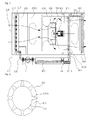
- FIG. 4 is a G-G cross sectional view for an annular water drain in FIG. 1 ;
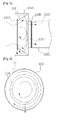
- FIG. 5 is an G-G cross sectional view for a depressurize chamber in FIG. 1 ;
- FIG. 6 is an operational front view for a conical duct in FIG. 5 ;
- FIG. 7 is a layout view for schematically showing a water reservoir in FIG. 1 ;
- a centrifugal wet type air cleaner for purifying contamination from air centrifugally by utilizing the direct rotation speed of a centrifugal impeller comprising: An air cleaner housing having a vaporizer for vaporizing washing water to form a wet air mixture; A reservoir mounted to the housing for supplying the washing water, the reservoir located upstream of the centrifugal impeller; and An annular vortex room located downstream of the centrifugal impeller for generating a centrifugal force on the wet air mixture by utilizing the direct rotation speed, the annular vortex room defined between an inner wall of the body and a gas passage cylinder mounted within the housing; Wherein the air being purified when contamination in the air is collected by the washing water in the wet air mixture, the wet air mixture subsequently flowing through the vortex room so that the centrifugal force separates the contamination and washing water from the
- a cone shaped annular water drain located downstream of the centrifugal impeller for collecting and draining water;
- the main body utilized as an air handling units, a gas dehumidifier, a humidifier, an anion generator, a vacuum cleaner and a car air conditioner, a constant temperature and humidity controller,
- a vaporizer connected with a water tap through a water pipe;
- the vaporizer included a water pump, a centrifugal vaporizer, a nozzle sprayer, and a ultra sonic humidifier, As shown in FIG.
- a centrifugal wet type air cleaner is comprised for purifying contamination from air centrifugally by utilizing the direct rotation speed of a centrifugal impeller, the air cleaner comprising: An air cleaner housing having a vaporizer for vaporizing washing water to form a wet air mixture; A reservoir mounted to the housing for supplying the washing water, the reservoir located upstream of the centrifugal impeller; and An annular vortex room located downstream of the centrifugal impeller for generating a centrifugal force on the wet air mixture by utilizing the direct rotation speed, the annular vortex room defined between an inner wall of the body and a gas passage cylinder mounted within the housing; Wherein the air being purified when contamination in the air is collected by the washing water in the wet air mixture, the wet air mixture subsequently flowing through the vortex room so that the centrifugal force separates the contamination and washing water from the purified air because of the difference between the specific gravities of the air and the washing water;, and a depressuri
- a centrifugal wet type air cleaner is comprised of the body utilizing for the air handling units, gas dehumidifiers, humidifiers, anion generator, vacuum cleaners and car air conditioners, and an auxiliary parts in a dehumidifier of compressed air system, refrigerate air conditioner, constant temperature and humidity controller.
- a centrifugal wet type air cleaner is comprised of a cone shaped annular water drain located downstream of the centrifugal impeller for collecting and draining water.
- a centrifugal wet type air cleaner is comprised of a clean air outlet having a flow path substantially perpendicular to the centrifugal force.
- FIG. 2 is a H-H cross sectional view for schematically showing the vortex-cylinder blades in FIG. 1 and FIG. 3 is an operational side view for air flow in FIG. 2
- a centrifugal wet type air cleaner is comprised of vortex chamber 904 mounted inside of housing 909 and formed with a vortex cylinder 913 supported by multiple vortex cylinder blades 916A.
- a centrifugal wet type air cleaner is comprised of an annular water drain 922 located downstream of the centrifugal impeller 908 inside of a housing 909. Wherein an annular water drain path 922A is formed on an annular water drain 922 with a drain outlet 911.
- a grill or screen usually called pre filter' is provided on the air inlet 905 for preventing large grain in air, and a water sprayer 903 is provided for generating fine mist of washing water. Therefore centrifugal impeller 908 is rotated with the power of electric motor 933 inside of a housing 909 for inducing air stream through an air inlet 905 communicated with a housing 909, and then liquid, especially water is atomized or sprayed by a water sprayer 903 from a liquid tank 901 as indicated by the arrows, thus scrubbing pollution substances in gas is scrubbed with the numerous atomizing liquid droplets as in the flow of fog or mist, wherein the pollution substances of gas are scrubbed efficiently with the viscosity of liquid mist or fine aqua droplets in the three-dimensional cubic vortex flow of fog or mist.
- FIG. 2 is an H-H cross sectional view for schematically showing the vortex-cylinder support in FIG. 1 , a vortex chamber 904 is formed between the inner cylinder 913 and the housing 909 for flowing vortex flow.
- a vortex blade (not shown) may be added for purifying severe pollution gas such as volatile organization compounds.
- FIG. 3 is an operational side view for air flow in FIG. 2 , the air is flowed centrifugally between the supporters 916A on the inner vortex cylinder 913 in the vortex chamber 904, and it is remained as in the state of vortex flow in the axial direction of a motor.
- FIG. 4 is an G-G cross sectional view for an annular water drain in FIG. 1 , the liquid containing pollution substances is collected with gravity effect at an annular water drain 922 and is drained along an annular water path 922A through a drain outlet 911 in a vortex chamber 904 inside of a housing 913. meanwhile the clean gas, especially 'fresh air', is discharged at a clean gas outlet 432 without leaking air through a liquid drain trap 441 as shown in FIG. 1 .
- FIG. 1 is a perspective view for schematically showing a centrifugal wet type air cleaner according to the present invention
- the contamination water is collected at a contamination reservoir 901A, and it is flowing at a fresh reservoir 901A by a water pump 16 through a water filter 14.
- a depressurize chamber is provided for preventing carry-over of water droplets by the difference of pressure between inside and outside of a main body in the present invention.
- FIG. 1 is a perspective view for schematically showing a centrifugal wet type air cleaner according to the present invention
- the washing water is supplied for a sprayer 903 by a water pump 16 through a supplying water pipe 16A.
- water pump 16 is utilized for sprayer 903 atomizing water.
- FIG. 1 is a perspective view for schematically showing a centrifugal wet type air cleaner according to the present invention, it is achieved for air conditioning with a heat exchanger unit 90A.
- a heat exchanger unit 90A is located downstream of the centrifugal impeller 908 at the outlet 932 of a main body 907, thus it is achieved for controlling humidity and temperature in discharging air.
- Central Air Conditioning System without conventional apparatus, such as a compressor, a condenser and chemical coolant, thus it is environmental apparatus for saving energy, reducing CO2 gas and for preventing global warming.
- a depressurize chamber 22C is located at the after body of a housing 909 for preventing carry-over of water at the gas outlet 932 and is formed inside of an annular conical duct 22 mounted inside of a housing 909. Further a depressurize chamber 22C may be added with a depressurize screen 22D to prevent for carry-over water at the gas outlet duct 22E. Wherein a depressurize screen 22D is able to flow air like a filter material. And an annular coffering 22A is formed around in front of a conical duct 22 for draining the contamination water.
- the contamination water is collected efficiently by the centrifugal force and the inertial force in the vortex flow of gas generated with the direct rotation speed of centrifugal impeller 908 and is drained with the structure of an annular conical duct 22.
- the contamination water is downwardly collected along an annular coffering 22A because water is heavier than the gas.
- it is achieved for air washing purifying effect efficiency to prevent carryover accompanied by scattering water droplets to the outside due to the difference of pressure between inside and outside of a main body 907.
- a depressurize chamber 22C to induce higher rotation speed of vortex flow on the speed of a centrifugal impeller.
- a depressurize chamber 22C is connected to gas outlet duct 22E with a duct coupler 22B.
- a depressurize chamber 22C may be naturally formed in side of a gas outlet duct 22E.
- FIG. 6 is an operational front view for a conical duct in FIG. 5 , the contamination water is collected, as indicated by the arrows, around an annular coffering 22A on a conical duct 22 and downwardly flowed a contamination water reservoir 901A through a drain outlet.
- FIG. 7 is an layout view for schematically showing a water reservoir in FIG. 1 , a water cooler is composed for cooling water inside of a water reservoir 901, and a oil-water separator 14C is composed for separating chemical oil from the toxic gas, such as volatile organization compounds.
- the volatile organization compounds such as a thermal gas-phase solvent, toluene, benzene, organic solvents, is converted as a liquid-phase by the cool water, and the contamination liquid is centrifugally separated as the water and oil with an oil water separator 14C.
- the contamination oil is downwardly flowed in an oil water separation reservoir 901B through an oil drain outlet 911A, meanwhile the contamination water is downwardly flowed in a contamination water reservoir 901A. Since a contamination water may be recycled after filtering with a water filter 14A.
- a water carbon filter 14A is utilized with carbon material for purifying volatile organization compounds, such as solvents.
- UV lamp 14B as an sterilizer is installed on a water reservoir 901 for sterilizing completely hospital germs, bacteria in standstill state for an enough time. thus it is supplied for fresh air.
- a sprayer 903 is utilized with humidification devices such as a water pump, rotating atomization devices, nozzle atomization devices, and ultrasonic means.
- a HEPA filter and a carbon filter can be used as a mechanical filter.
- wet type air cleaner utilizing a centrifugal impeller with a liquid sprayer and gas-liquid centrifugal separator for cleaning gases, especially air is achieved for more than 99 percentage air purification efficiency with the aqua viscosity of fine water droplets in the positive 3 dimensional vortex flow, neutralization reaction with harmful gaseous substances, centrifugal separating on the basis of different specific density, especially air to water 1 to 1000, automatic sterilization without chemical addicts.
- the Gas-liquid centrifugal separator may be provided for the auxiliary part of a complex air cleaner and air condition system.
- Optional blank
Landscapes
- Chemical & Material Sciences (AREA)
- Chemical Kinetics & Catalysis (AREA)
- Engineering & Computer Science (AREA)
- Combustion & Propulsion (AREA)
- Mechanical Engineering (AREA)
- General Engineering & Computer Science (AREA)
- Separation Of Particles Using Liquids (AREA)
- Disinfection, Sterilisation Or Deodorisation Of Air (AREA)
- Physical Water Treatments (AREA)
- Cyclones (AREA)
- Water Treatment By Sorption (AREA)
- Air Humidification (AREA)
- Structures Of Non-Positive Displacement Pumps (AREA)
- Drying Of Gases (AREA)
- Separating Particles In Gases By Inertia (AREA)
Abstract
Description
- This invention relates to a wet type air cleaner utilizing a centrifugal impeller for fresh air, thus firstly airborne fine particulate dust, noxious gases and odor particles, pathogens, and the number of cleaning bacteria trapped using the water droplets in the scrubbing room, and secondarily the pollutant water is centrifugally separated from air on the basis of the difference between the specific gravity of gases and liquids (approximately1:1000) with using high-speed rotating centrifugal impeller with a powerful strength of the centrifugal force causes the vortex structure in the base to cleanse the air or gas, since scrubbing the pollution material including dust, harmful gaseous substances, virus and bacteria in air with the positive three dimensional vortex stream of water droplets, mist and fog on the basis of natural water instead of using solid filters with utilizing a depressing room on the outlet of a body.
This invention relates to a wet type air cleaner utilizing a centrifugal impeller for fresh air, thus the separation of pollution substances with scrubbing liquid can be absolutely eliminated from air with utilizing the difference of specific gravity (approximately 1:1000) between air and liquid by the strength of centrifugal force in the vortex generating structure such as centrifugal impeller, since scrubbing the pollution material including dust, harmful gaseous substances, virus and bacteria in air with the positive three dimensional vortex stream of fine water droplets, mist and fog on the basis of natural water instead of using solid filters with utilizing a depression room on the outlet of a body. - In this atmosphere, the air include bacteria, pathogens, sand and toxic gases, smoke, dust, oil, water, tire dust, pollen and a fine dust sizing smaller than 0,1µm, the smell particles are a mixture of pollutants.
- The invention primarily airborne fine particulate dust, noxious gases and odor particles, pathogens, and bacteria by washing water collected in the wet air with lot of water droplets, and secondarily the wet air can be purged with high efficiency on the basis on the difference between the specific gravity of gases and liquids (1:1000), thus the pollution can be purify from the air with centrifugal separation based on the rotation speed of the centrifugal impeller for generating vortex flow and with the positive three dimensional vortex stream of fine water droplets, mist and fog on the basis of natural water instead of using solid filters.
- The disadvantages of the conventional air cleaner are classified with the following type; a Solid Filter: low purification efficiency due to clogging of pollution dust, unsanitary germ culture, occurring in succession of junk pollution material, further a mechanical filter type typically used in solid form, but fully capture fine particulate dust and does not purify, and sometimes breeding out pathogens, or germs, especially in hospital, with periodic replacement of maintenance problems, and it has a problem with a non-woven fabric filter to generate secondary pollutants and environmental pollution, and it may be wasted lot of electric energy consumption with plugging, further it causes global warming.
- More photo catalyst, electrostatic precipitation, plasma air purifying device have poor efficiency with a non-conductive, 1µm or less with a fine-particles, and electrostatic precipitation method or anion air purifier occurs side effects with harmful ozone for human health.
- Conventional dry centrifugal type of air purifier in theory less than 85% of the air purification efficiency, it is impractical purification for the 5µm or less with a fine particulate dust, pollen, cigarette smoke, toxic gases trapping, and it is not suitable for demanding industrial clean rooms by centrifuging simply to remove for the less 0.3µm or less fine particles in the level of 99.9%.
- On the other hand, the conventional wet type air purifiers; it purifies pollutants in the air flow to attract simply the two-dimensional surface area contact by the viscosity of water. Therefore, most pollutants do not contact the surface water film, thus purification efficiency is low as less than 20 percent level for the standard reference of 0.3 µm particles, and discharging excessive moisture emissions to outlets, it yields corrosion problem. further it is unable to remove 0,1µm or less particles including pathogens, microbial pathogens, hazardous gas. thus it is lack of ability to use industrial clean rooms, hospital facilities for the level of 99.9% air-purifying efficiency or the standard reference of 0.3 µm particles.
- conventional humidifying air purifier or anion generating air purifier has good effect, but it has a problem with low air cleaning efficiency due to excessive moisture, since moisture-containing pollutants is accompanied with the exhaust air exit as in low air cleaning efficiency, thus contamination with even more moisture, so the emission has been known more harmful to human health.
- Meanwhile, in the conventional way of indirect vortex flow, centrifugal air handling fans installed on the outside by the airflow supplied by the centrifugal method is indirect. Because the air supply from outside the centrifuge speed is very low, thus it had low air cleaning efficiency by 10% to 20% with discharging lot of the moisture and humidity, it had a low air cleaning efficiency due to excessive moisture occurs.
- This present invention has been improved for centrifugal wet type cleaning air conditioner having a heat transfer, an air duct, a water circulator from a continuation in art of my Patent family from PCT International Publication Number
WO 2006/112590 Al WO 2005/075799 Al publicized on Aug. 18, 2005, WET TYPE PURIFICATION APPARATUS UTILIZING A CENTRIFUGAL IMPELLER and the ROK application laid-open No.10-2005-0099316 WO 2005/075799 was applied on the basis of the ROK application laid-open No.10-2004-0008187 10-2004-0079691 10-2004-0080482 - However, it has a problem with discharging out by carryover the washing water containing pollutants. Since it is occurred the pressure difference between inside and outside of the product. It was found that the flow of air to discharge with the water out of the centrifugal separation cylinder. The water containing the pollutants is discharged to the outside with the pollutants. Thus it has low air purification efficiency. In addition, it has a problem recycling water without filtering pollutants.
- Therefore, in order to improve the problems of the present invention as the same applicant and the inventor of the prior art, it is solved by adding an annular cone-based depressed room functions, a water filter, and a water drainer. Thus it prevents the carry-over of washing water outside.
Further the washing water can recycle and drain efficiently by controlling centrifugal force of inertia and centrifugal force of a centrifugal impeller at the outlet of the centrifugal separation cylinder. Furthermore it is upgraded for air cleaning efficiency by making a high rotation speed of centrifugal impeller with the added devices. - In addition, it is upgraded for air cleaning efficiency from the prior art by adding an annular cone-based depressed room functions, a water filter, and a water drainer to recycle washing water completely. Therefore, it saves lot of electric energy. Thus it may be an environmental apparatus for preventing global warming by reducing CO2.
- The present invention, the conventional problems as described above is intended to improve the air cleaning efficiency for purifying pollutants including dust, bacteria, and dirty gas by separating centrifugally on the basis of specific gravity difference between air and water without a conventional solid filter. Thus it is upgraded for high-performance efficiency by adding an annular cone-based depressed room functions, a water filter, and a water drainer. Thus it prevents the carry-over of washing water outside.
- To achieve these objectives the present invention, water-trapping pollutants in the air, and air and water by the difference between wet air gravity centrifugation to purify the air of a centrifugal type air cleaner in wet type, air intake body to (907) inhalant gas at (905), and the gas inhalant (905) came in to spray into the air cleaning unit number (907) is installed in the humidifying unit (903), and air pollution of water was sprayed As a three-dimensional trapping scrubbing room (902), and wet air attract and direct the fan's rotation generates centrifugal force to the body wet air (907) is installed in the centrifugal impeller (908), and the centrifugal impeller (908) of the is installed to keep the centrifugal force in the downstream wet air cyclone room(904), and was to be divided, and Centrifugal cleaning water to collect and wastewater treatment unit (907) installed in the interior of the ring of the water drainer (922), and water drainer (922) of the formed in the water due to internal pressure differential scattering (CARRY OVER) is installed to prevent water carry-over with a DEPRESSURIZED chamber 22C, with and water drainer (922) for storing washing water from the centrifugal cleaning by making Canteen (901), and clean canteen (901) from the inside of the water to cleanse and recycle water filter is installed (WATER FILTER, 14) that includes a centrifuge of the type wherein wet type air purifier is configured.
- Wet type air cleaner utilizing a centrifugal impeller is to eliminate the disadvantages mentioned above and to provide an advantage appliance with aqua viscosity of fine water droplets in the positive three dimensional vortex flow, neutralization reaction with harmful gaseous substances, centrifugal separating on the basis of different specific density, especially air: water 1:1,000, automatic sterilization without pasteurization chemicals according to this invention.
It is composed of atomizer for generating Fine water droplets (0.3.quadrature.) as in the vortex flow on the basis of positive 3 dimensional scrubbing with aqua viscosity cohesion gas-liquid centrifugal separator for preventing a high humidification problem with utilizing the different specific density (1:1,000, air: water), and liquid circulation pump for reusing liquid for a long time without frequently refilling. Wherein the sort of atomizer comprises aerodynamic venturing tube, ultra sonic vibration, air-water nozzle with blower or compressor. - Wet type air cleaner utilizing a centrifugal impeller with a liquid sprayer and gas-liquid centrifugal separator for cleaning gases, especially air is achieved for more than 99.9% air purification efficiency on the reference of less than 0,1µm with the aqua viscosity of fine water droplets in the vortex flow, neutralization reaction with harmful gaseous substances, centrifugal separating on the basis of different specific density without chemical addicts.
- This apparatus is based on natural water, thus it is advantages of no more succession of junk pollution material such as an abolished solid filter.
As a result, it is applicable for fresh air in hospital facility including a baby room, an aseptic surgery, and a patient room, an automobile cabin, home appliances, office, and a school facility, and an industrial facility for semi conduct manufacturing, chemical process, clean room, aseptic laboratory, and military tools for chemical, biological and radiological (CBR) warfare including a personal soldier, a bunker, a tank et al.
The Gas-liquid centrifugal separator may be provided as an auxiliary part of a complex air cleaner or air condition system. - It is provided for Natural negative ions by water as a waterfall effect. In that way, harmful gas ozone (03) have no side effects occurred, such as electrostatic precipitation.
-
FIG. 1 is a perspective view for schematically showing a centrifugal wet type air cleaner according to the present invention; -
FIG. 2 is an H-H cross sectional view for schematically showing the vortex-cylinder blades inFIG. 1 ; -
FIG. 3 is an operational side view for air flow inFIG. 2 ; -
FIG. 4 is a G-G cross sectional view for an annular water drain inFIG. 1 ; - As shown in
FIG. 5 is an G-G cross sectional view for a depressurize chamber inFIG. 1 ; -
FIG. 6 is an operational front view for a conical duct inFIG. 5 ; -
FIG. 7 is a layout view for schematically showing a water reservoir inFIG. 1 ; - Best Mode for Carrying out the Invention Preferred embodiments of the present invention will be explained hereafter with reference to accompanied embodiments.
As shown inFIG. 1 , A centrifugal wet type air cleaner for purifying contamination from air centrifugally by utilizing the direct rotation speed of a centrifugal impeller, the air cleaner comprising: An air cleaner housing having a vaporizer for vaporizing washing water to form a wet air mixture; A reservoir mounted to the housing for supplying the washing water, the reservoir located upstream of the centrifugal impeller; and An annular vortex room located downstream of the centrifugal impeller for generating a centrifugal force on the wet air mixture by utilizing the direct rotation speed, the annular vortex room defined between an inner wall of the body and a gas passage cylinder mounted within the housing; Wherein the air being purified when contamination in the air is collected by the washing water in the wet air mixture, the wet air mixture subsequently flowing through the vortex room so that the centrifugal force separates the contamination and washing water from the purified air because of the difference between the specific gravities of the air and the washing water;, and a depressurize chamber located downstream of the centrifugal impeller for preventing carry-over of the water, and a water filter mounted inside of the reservoir for recycling refresh washing water;,
As shown inFIG. 4 , further comprising: a cone shaped annular water drain located downstream of the centrifugal impeller for collecting and draining water;,
As shown inFIG. 1 , further comprising: the main body utilized as an air handling units, a gas dehumidifier, a humidifier, an anion generator, a vacuum cleaner and a car air conditioner, a constant temperature and humidity controller,
As shown inFIG. 1 , further comprising: a vaporizer connected with a water tap through a water pipe;,
As shown inFIG. 1 , further comprising: the vaporizer included a water pump, a centrifugal vaporizer, a nozzle sprayer, and a ultra sonic humidifier,
As shown inFIG. 7 , further comprising: the water cooler mounted inside of the reservoir;, As shown inFIG. 7 , further comprising: the oil water separator connected with the reservoir through a water pipe;,
As shown inFIG. 7 , further comprising: the water filter utilized with carbon material;,
As shown inFIG. 7 , further comprising: the sterilizer mounted inside of the reservoir;,
As shown inFIG. 1 , further comprising: the main body manufactured perpendicular to the ground. - As shown in
FIG. 1 , A centrifugal wet type air cleaner is comprised for purifying contamination from air centrifugally by utilizing the direct rotation speed of a centrifugal impeller, the air cleaner comprising: An air cleaner housing having a vaporizer for vaporizing washing water to form a wet air mixture; A reservoir mounted to the housing for supplying the washing water, the reservoir located upstream of the centrifugal impeller; and An annular vortex room located downstream of the centrifugal impeller for generating a centrifugal force on the wet air mixture by utilizing the direct rotation speed, the annular vortex room defined between an inner wall of the body and a gas passage cylinder mounted within the housing; Wherein the air being purified when contamination in the air is collected by the washing water in the wet air mixture, the wet air mixture subsequently flowing through the vortex room so that the centrifugal force separates the contamination and washing water from the purified air because of the difference between the specific gravities of the air and the washing water;, and a depressurize chamber located downstream of the centrifugal impeller for preventing carry-over of the water, and a water filter mounted inside of the reservoir for recycling refresh washing water. - As shown in
FIG. 1 , A centrifugal wet type air cleaner is comprised of the body utilizing for the air handling units, gas dehumidifiers, humidifiers, anion generator, vacuum cleaners and car air conditioners, and an auxiliary parts in a dehumidifier of compressed air system, refrigerate air conditioner, constant temperature and humidity controller. - As shown in
FIG. 1 , A centrifugal wet type air cleaner is comprised of a cone shaped annular water drain located downstream of the centrifugal impeller for collecting and draining water. - As shown in
FIG. 1 , a centrifugal wet type air cleaner is comprised of a clean air outlet having a flow path substantially perpendicular to the centrifugal force. - As shown in
FIG. 2 is a H-H cross sectional view for schematically showing the vortex-cylinder blades inFIG. 1 andFIG. 3 is an operational side view for air flow inFIG. 2 , A centrifugal wet type air cleaner is comprised ofvortex chamber 904 mounted inside ofhousing 909 and formed with avortex cylinder 913 supported by multiplevortex cylinder blades 916A. - As shown in
FIG. 4 is an G-G cross sectional view for an annular water drain inFIG. 1 , A centrifugal wet type air cleaner is comprised of anannular water drain 922 located downstream of thecentrifugal impeller 908 inside of ahousing 909. Wherein an annularwater drain path 922A is formed on anannular water drain 922 with adrain outlet 911. - As described above, according to the present invention is based on the configuration works in conjunction with the accompanying drawings illustrating a more detailed description of them is as follows.
- As shown in
Figure 1 , a grill or screen usually called pre filter' is provided on theair inlet 905 for preventing large grain in air, and awater sprayer 903 is provided for generating fine mist of washing water. Thereforecentrifugal impeller 908 is rotated with the power ofelectric motor 933 inside of ahousing 909 for inducing air stream through anair inlet 905 communicated with ahousing 909, and then liquid, especially water is atomized or sprayed by awater sprayer 903 from aliquid tank 901 as indicated by the arrows, thus scrubbing pollution substances in gas is scrubbed with the numerous atomizing liquid droplets as in the flow of fog or mist, wherein the pollution substances of gas are scrubbed efficiently with the viscosity of liquid mist or fine aqua droplets in the three-dimensional cubic vortex flow of fog or mist. - As shown in
FIG. 2 is an H-H cross sectional view for schematically showing the vortex-cylinder support inFIG. 1 , avortex chamber 904 is formed between theinner cylinder 913 and thehousing 909 for flowing vortex flow. A vortex blade (not shown) may be added for purifying severe pollution gas such as volatile organization compounds. - As shown in
FIG. 3 is an operational side view for air flow inFIG. 2 , the air is flowed centrifugally between thesupporters 916A on theinner vortex cylinder 913 in thevortex chamber 904, and it is remained as in the state of vortex flow in the axial direction of a motor. Thus it is efficiently achieved for separating the contamination water from air for a long time inside of ahousing 909.
As shown inFIG. 4 is an G-G cross sectional view for an annular water drain inFIG. 1 , the liquid containing pollution substances is collected with gravity effect at anannular water drain 922 and is drained along anannular water path 922A through adrain outlet 911 in avortex chamber 904 inside of ahousing 913. meanwhile the clean gas, especially 'fresh air', is discharged at a clean gas outlet 432 without leaking air through a liquid drain trap 441 as shown inFIG. 1 . - Hereafter, as shown in
FIG. 1 is a perspective view for schematically showing a centrifugal wet type air cleaner according to the present invention, the contamination water is collected at acontamination reservoir 901A, and it is flowing at afresh reservoir 901A by awater pump 16 through awater filter 14. - Therefore it is achieved for more than 99% air purification efficiency with the aqua viscosity of water droplets as a three dimensional scrubbing effect in stage 1 and with the centrifugal separation by direct rotation speed of a centrifugal impeller in stage 2, the basis of different specific gravity, especially air: water 1:1,000 approximately. Further a depressurize chamber is provided for preventing carry-over of water droplets by the difference of pressure between inside and outside of a main body in the present invention.
- As shown in
FIG. 1 is a perspective view for schematically showing a centrifugal wet type air cleaner according to the present invention, the washing water is supplied for asprayer 903 by awater pump 16 through a supplyingwater pipe 16A. Whereinwater pump 16 is utilized forsprayer 903 atomizing water. - As shown in
FIG. 1 is a perspective view for schematically showing a centrifugal wet type air cleaner according to the present invention, it is achieved for air conditioning with aheat exchanger unit 90A. Wherein aheat exchanger unit 90A is located downstream of thecentrifugal impeller 908 at the outlet 932 of a main body 907, thus it is achieved for controlling humidity and temperature in discharging air. Further it is utilized for Central Air Conditioning System without conventional apparatus, such as a compressor, a condenser and chemical coolant, thus it is environmental apparatus for saving energy, reducing CO2 gas and for preventing global warming. - As shown in
FIG. 5 is an G-G cross sectional view for a depressurize chamber located downstream of acentrifugal impeller 908 inFIG. 1 , a depressurize chamber 22C is located at the after body of ahousing 909 for preventing carry-over of water at the gas outlet 932 and is formed inside of an annularconical duct 22 mounted inside of ahousing 909. Further a depressurize chamber 22C may be added with adepressurize screen 22D to prevent for carry-over water at thegas outlet duct 22E. Wherein adepressurize screen 22D is able to flow air like a filter material. And anannular coffering 22A is formed around in front of aconical duct 22 for draining the contamination water.
Further the contamination water is collected efficiently by the centrifugal force and the inertial force in the vortex flow of gas generated with the direct rotation speed ofcentrifugal impeller 908 and is drained with the structure of an annularconical duct 22. Thus the contamination water is downwardly collected along anannular coffering 22A because water is heavier than the gas.
As described above, it is achieved for air washing purifying effect efficiency to prevent carryover accompanied by scattering water droplets to the outside due to the difference of pressure between inside and outside of a main body 907.
further it is achieved for better air clean efficiency with a depressurize chamber 22C to induce higher rotation speed of vortex flow on the speed of a centrifugal impeller. Wherein a depressurize chamber 22C is connected togas outlet duct 22E with aduct coupler 22B. Furthermore a depressurize chamber 22C may be naturally formed in side of agas outlet duct 22E. - As shown in
FIG. 6 is an operational front view for a conical duct inFIG. 5 , the contamination water is collected, as indicated by the arrows, around anannular coffering 22A on aconical duct 22 and downwardly flowed acontamination water reservoir 901A through a drain outlet. - As shown in
FIG. 7 is an layout view for schematically showing a water reservoir inFIG. 1 , a water cooler is composed for cooling water inside of awater reservoir 901, and a oil-water separator 14C is composed for separating chemical oil from the toxic gas, such as volatile organization compounds.
As described above, the volatile organization compounds, such as a thermal gas-phase solvent, toluene, benzene, organic solvents, is converted as a liquid-phase by the cool water, and the contamination liquid is centrifugally separated as the water and oil with anoil water separator 14C. Thus the contamination oil is downwardly flowed in an oilwater separation reservoir 901B through anoil drain outlet 911A, meanwhile the contamination water is downwardly flowed in acontamination water reservoir 901A. Since a contamination water may be recycled after filtering with awater filter 14A. - Meanwhile, a
water carbon filter 14A is utilized with carbon material for purifying volatile organization compounds, such as solvents. - Further a
UV lamp 14B as an sterilizer is installed on awater reservoir 901 for sterilizing completely hospital germs, bacteria in standstill state for an enough time. thus it is supplied for fresh air. - Wherein a
sprayer 903 is utilized with humidification devices such as a water pump, rotating atomization devices, nozzle atomization devices, and ultrasonic means. - Depending on the purpose of the present invention uses a pre-filter, a HEPA filter and a carbon filter can be used as a mechanical filter.
- Wet type air cleaner utilizing a centrifugal impeller with a liquid sprayer and gas-liquid centrifugal separator for cleaning gases, especially air is achieved for more than 99 percentage air purification efficiency with the aqua viscosity of fine water droplets in the positive 3 dimensional vortex flow, neutralization reaction with harmful gaseous substances, centrifugal separating on the basis of different specific density, especially air to water 1 to 1000, automatic sterilization without chemical addicts.
As a result, it is applicable for fresh air in hospital facility including baby room, aseptic surgery, and patient room, automobile, home appliances, office, and school, and industrial facility for semi conduct manufacturing, chemical process, clean room, aseptic laboratory, and military tools for chemical, biological and radiological (CBR) warfare including a personal soldier, a bunker, a tank et al.
The Gas-liquid centrifugal separator may be provided for the auxiliary part of a complex air cleaner and air condition system.
Optional blank
Claims (10)
- A centrifugal wet type air cleaner for purifying contamination from air centrifugally by utilizing the direct rotation speed of a centrifugal impeller, the air cleaner comprising: An air cleaner housing having a vaporizer for vaporizing washing water to form a wet air mixture; A reservoir mounted to the housing for supplying the washing water, the reservoir located upstream of the centrifugal impeller; and An annular vortex room located downstream of the centrifugal impeller for generating a centrifugal force on the wet air mixture by utilizing the direct rotation speed, the annular vortex room defined between an inner wall of the body and a gas passage cylinder mounted within the housing; Wherein the air being purified when contamination in the air is collected by the washing water in the wet air mixture, the wet air mixture subsequently flowing through the vortex room so that the centrifugal force separates the contamination and washing water from the purified air because of the difference between the specific gravities of the air and the washing water; and a depressurize chamber located downstream of the centrifugal impeller for preventing carry-over of the water, and a water filter mounted inside of the reservoir for recycling refresh washing water.
- A centrifugal wet type air cleaner as claimed in claim 1, further comprising: a cone shaped annular water drain located downstream of the centrifugal impeller for collecting and draining water.
- A centrifugal wet type air cleaner as claimed in claim 1, further comprising: the main body utilized as an air handling units, a gas dehumidifier, a humidifier, an anion generator, a vacuum cleaner and a car air conditioner, a constant temperature and humidity controller.
- A centrifugal wet type air cleaner as claimed in claim 1, further comprising: the vaporizer connected with a water tap through a water pipe.
- A centrifugal wet type air cleaner as claimed in claim 1, further comprising: the vaporizer included a water pump, a centrifugal vaporizer, a nozzle sprayer, and a ultra sonic humidifier.
- A centrifugal wet type air cleaner as claimed in claim 1, further comprising: the water cooler mounted inside of the reservoir.
- A centrifugal wet type air cleaner as claimed in claim 1, further comprising: the oil water separator connected with the reservoir through a water pipe.
- A centrifugal wet type air cleaner as claimed in claim 1, further comprising: the water filter utilized with carbon material.
- A centrifugal wet type air cleaner as claimed in claim 1, further comprising: the sterilizer mounted inside of the reservoir.
- A centrifugal wet type air cleaner as claimed in claim 1, further comprising; the main body manufactured perpendicular to the ground.
Applications Claiming Priority (2)
| Application Number | Priority Date | Filing Date | Title |
|---|---|---|---|
| KR1020090075461A KR20110017800A (en) | 2009-08-14 | 2009-08-14 | Centrifugal wet type horizontal air conditioner |
| PCT/KR2010/005190 WO2011019170A2 (en) | 2009-08-14 | 2010-08-08 | Centrifugal, wet-type air cleaner |
Publications (2)
| Publication Number | Publication Date |
|---|---|
| EP2466085A2 true EP2466085A2 (en) | 2012-06-20 |
| EP2466085A4 EP2466085A4 (en) | 2013-03-27 |
Family
ID=43586620
Family Applications (1)
| Application Number | Title | Priority Date | Filing Date |
|---|---|---|---|
| EP10808319A Withdrawn EP2466085A4 (en) | 2009-08-14 | 2010-08-08 | Centrifugal, wet-type air cleaner |
Country Status (14)
| Country | Link |
|---|---|
| US (1) | US20130025462A1 (en) |
| EP (1) | EP2466085A4 (en) |
| JP (1) | JP2013501614A (en) |
| KR (1) | KR20110017800A (en) |
| CN (1) | CN102834593A (en) |
| AU (1) | AU2010283139A1 (en) |
| BR (1) | BR112012003195A2 (en) |
| CA (1) | CA2770988A1 (en) |
| IL (1) | IL218053A0 (en) |
| IN (1) | IN2012DN02115A (en) |
| MX (1) | MX2012001894A (en) |
| RU (1) | RU2012108201A (en) |
| WO (1) | WO2011019170A2 (en) |
| ZA (1) | ZA201201848B (en) |
Cited By (4)
| Publication number | Priority date | Publication date | Assignee | Title |
|---|---|---|---|---|
| CN107388444A (en) * | 2017-07-11 | 2017-11-24 | 南昌航空大学 | A kind of New Vortex purification of air refrigerated medium warmer |
| TWI617776B (en) * | 2016-10-14 | 2018-03-11 | Clean air system | |
| TWI814060B (en) * | 2021-08-18 | 2023-09-01 | 奇鼎科技股份有限公司 | Water-washing moisture recovery system |
| IT202200004259A1 (en) | 2022-03-07 | 2023-09-07 | Univ Degli Studi Di Milano Bicocca | Filtration and decontamination device for regenerating air |
Families Citing this family (51)
| Publication number | Priority date | Publication date | Assignee | Title |
|---|---|---|---|---|
| US9061230B2 (en) * | 2012-10-24 | 2015-06-23 | Yaser K. Barakat | System to remove contaminants from air stream |
| CN103223286A (en) * | 2013-04-28 | 2013-07-31 | 沁园集团股份有限公司 | Air purification apparatus with functions of water production and separation membrane water purification |
| CN103405977B (en) * | 2013-08-06 | 2015-01-28 | 浙江海亮能源管理有限公司 | Multi-stage spray treatment device for waste gas of printing and dyeing setting machine |
| US9259675B2 (en) * | 2013-11-11 | 2016-02-16 | Andover Protection Systems, Llc | Centripetal separation system for cleaning particulate-pervaded air or gas |
| DE102013019328B4 (en) * | 2013-11-20 | 2019-02-21 | Mann+Hummel Gmbh | Tank ventilation filter with a constriction in the air inlet area |
| DE102015200851A1 (en) * | 2014-02-10 | 2015-08-13 | MAHLE Behr GmbH & Co. KG | Assembly for an air conditioning system |
| CN104976714A (en) * | 2014-04-08 | 2015-10-14 | 梁嘉麟 | Air purification device with water spraying as main part and semiconductor refrigeration thermal effect as auxiliary part |
| KR101485405B1 (en) * | 2014-05-21 | 2015-01-26 | 노경진 | Air cleaner using water |
| US9682345B2 (en) | 2014-07-08 | 2017-06-20 | Particle Measuring Systems, Inc. | Method of treating a cleanroom enclosure |
| CN104511220B (en) * | 2014-12-01 | 2017-09-05 | 苏州盟通利机电设备有限公司 | The cavity arrangements structure of rinsing type air purifier |
| KR101514195B1 (en) * | 2015-02-17 | 2015-04-23 | 주식회사 에코에너젠 | Energy-Saving Type Dielectric Barrier Discharge Plasma NOx Reduction Equipment |
| CN104776506B (en) * | 2015-04-30 | 2017-11-03 | 青岛鑫中天创新生物医药科技研究所有限公司 | A kind of air water washing cleaning device |
| WO2016190675A1 (en) * | 2015-05-27 | 2016-12-01 | Samsung Electronics Co., Ltd. | Humidifying apparatus |
| CN105251300B (en) * | 2015-10-16 | 2017-12-22 | 盐城工学院 | A kind of tunnel cave waste gas dust-removal device and dust removal method |
| CN105363331A (en) * | 2015-11-12 | 2016-03-02 | 江苏金鹏环境科技集团有限公司 | Air purification system |
| CN105275843A (en) * | 2015-11-20 | 2016-01-27 | 马加良 | Remote control stepless speed regulating ceiling fan with humidifying function |
| CN105363313A (en) * | 2015-12-14 | 2016-03-02 | 海峡医疗器械工程研究中心(常州)有限公司 | Wet-type purification device for fine suspended particles auxiliary purification |
| KR101687609B1 (en) * | 2016-03-17 | 2017-01-02 | 박병천 | Wastewater treatment apparatus |
| WO2017195282A1 (en) * | 2016-05-10 | 2017-11-16 | 株式会社アクシス | Air purifier |
| CN106196223A (en) * | 2016-08-31 | 2016-12-07 | 惠州市富的旺旺实业发展有限公司 | A kind of biological electrostatic oil and smoke cleaner and purification method thereof |
| CN106362507B (en) * | 2016-11-29 | 2019-05-03 | 山东百特淂威节能装备有限公司 | Air cleaning unit and non-negative pressure water-supply device |
| KR101955412B1 (en) * | 2017-04-14 | 2019-03-08 | 고등기술연구원연구조합 | Fine dust collecting apparatus |
| CN106975298A (en) * | 2017-05-12 | 2017-07-25 | 王红燕 | A kind of lift Environmental-protecting dust-removing sprayer unit |
| CN107269348B (en) * | 2017-07-11 | 2019-03-01 | 丁乃祥 | Internal combustion engine exhaust silencer |
| CN108043123A (en) * | 2017-12-15 | 2018-05-18 | 安徽喜尔奇日用品有限公司 | A kind of Household air purifier for being easily changed cleaning |
| CN108201782A (en) * | 2018-01-16 | 2018-06-26 | 王保行 | A kind of boiler flue gas purification technique |
| CN108758892B (en) * | 2018-06-03 | 2020-10-30 | 浙江金果知识产权有限公司 | Air purifying device |
| CN108837642B (en) * | 2018-07-09 | 2021-03-16 | 漳州科晖专用汽车制造有限公司 | High-efficient environmental protection dust collector |
| CN109010895A (en) * | 2018-07-11 | 2018-12-18 | 郑州大学第附属医院 | A kind of severe ward air sterilization device |
| CN109114669B (en) * | 2018-08-13 | 2020-06-26 | 黄鲁生 | Water mist air purifying device |
| US10245546B1 (en) | 2018-08-22 | 2019-04-02 | H & H Inventions & Enterprises, Inc. | Exhaust gas purification method and system |
| KR102178733B1 (en) * | 2018-09-28 | 2020-11-13 | 주식회사 포스코 | Alien substance capturing apparatus and electrical steel sheet manufacturing facility having thereof |
| CN112236205B (en) * | 2018-12-14 | 2022-12-27 | 松下知识产权经营株式会社 | Air purification device and air purification method |
| CN109827258B (en) * | 2019-02-25 | 2020-12-18 | 佛山市耐堡电气有限公司 | Air purifier with multilayer purification performance |
| SE544065C2 (en) | 2019-03-05 | 2021-11-30 | 3Nine Ab | Method and apparatus for cleaning an air flow from particles |
| CN110118400A (en) * | 2019-05-13 | 2019-08-13 | 浙江理工大学 | Multifunctional air clarifying device and method based on cryogenic condensation |
| CN110180303A (en) * | 2019-05-23 | 2019-08-30 | 淄博棠鸣机电科技有限公司 | One kind extending out formula high-temperature waste gas treating apparatus |
| CN110201476A (en) * | 2019-06-26 | 2019-09-06 | 广西南宁天树峰美环保科技有限公司 | A kind of lampblack purifying system with indoor temperature control function |
| CN111359433A (en) * | 2020-04-17 | 2020-07-03 | 漳州市昱琪丰金属结构件有限公司 | Integrative treatment facility of high concentration high temperature waste gas |
| CN111663987A (en) * | 2020-06-05 | 2020-09-15 | 合肥神舟催化净化器股份有限公司 | Automobile exhaust catalytic purification device |
| US11543140B2 (en) * | 2020-06-05 | 2023-01-03 | Christopher Cawley | Combination humidifier / dehumidifier with common water containment and outdoor air intake |
| TWI720922B (en) * | 2020-07-21 | 2021-03-01 | 沅錠科技有限公司 | Impeller type exhaust gas treatment device |
| CN112211696B (en) * | 2020-10-12 | 2021-07-16 | 柳州市通顺汽车部件有限责任公司 | Cooling and water removing device for automobile exhaust pipe |
| CN112295006B (en) * | 2020-11-05 | 2022-05-17 | 广州市合联科技发展有限公司 | Air cleaning and sterilizing device and method |
| CN113063204A (en) * | 2021-05-07 | 2021-07-02 | 郑州世峰节能科技有限公司 | Air purification system of centrifugal washing sterilization air conditioning unit |
| CN113063205A (en) * | 2021-05-07 | 2021-07-02 | 郑州世峰节能科技有限公司 | Air purification device with centrifugal washing sterilization function |
| CN113638892B (en) * | 2021-08-10 | 2022-06-21 | 萨震压缩机(上海)有限公司 | High-speed centrifugal air compressor capable of supercharging through air inlet |
| CN114733297A (en) * | 2022-04-28 | 2022-07-12 | 刘胜利 | Dustproof device for building construction |
| CN116292339B (en) * | 2023-04-12 | 2024-02-06 | 广东鑫风风机有限公司 | Centrifugal fan with self-cleaning function |
| CN117547920B (en) * | 2024-01-09 | 2024-04-02 | 三鑫特材(常州)股份有限公司 | Dust collector of rolling mill export |
| CN118059620B (en) * | 2024-04-25 | 2024-07-05 | 山西浩森洗涤机械制造有限公司 | Gas washer |
Citations (3)
| Publication number | Priority date | Publication date | Assignee | Title |
|---|---|---|---|---|
| US3216182A (en) * | 1964-10-06 | 1965-11-09 | Gen Electric | Axial flow vapor-liquid separator |
| US3960524A (en) * | 1973-12-28 | 1976-06-01 | Cumpston Jr Edward H | Air scrubber |
| US20020139249A1 (en) * | 2001-03-28 | 2002-10-03 | Darren Livingston | Acceleration assisted particle/gas separation system |
Family Cites Families (24)
| Publication number | Priority date | Publication date | Assignee | Title |
|---|---|---|---|---|
| JPS4899077A (en) * | 1972-03-29 | 1973-12-15 | ||
| US3800505A (en) * | 1972-10-11 | 1974-04-02 | Air Pollution Specialties Inc | Method and apparatus for removing oil from effluent gas |
| US3898059A (en) * | 1973-05-09 | 1975-08-05 | Chester L Foster | Method and apparatus for treating polluted air along auto traffic arteries |
| US3913345A (en) * | 1974-04-29 | 1975-10-21 | William H Goettl | Air conditioner |
| US4263099A (en) * | 1979-05-17 | 1981-04-21 | Bethlehem Steel Corporation | Wet quenching of incandescent coke |
| JPS6168113A (en) * | 1984-09-08 | 1986-04-08 | Nippon Oil Eng Kk | Method and apparatus for washing gas |
| US5180405A (en) * | 1992-06-09 | 1993-01-19 | Chi Chang Enterprises Co., Ltd. | Oily smoke purifying apparatus of central processing system type |
| AU2085095A (en) * | 1994-03-31 | 1995-10-23 | Eiichi Sugiura | Washing device and oily water separator and filtration device which are optimal for use with the washing device |
| US6019819A (en) * | 1998-03-17 | 2000-02-01 | Alpha Engineers, Inc. | Apparatus and method for extracting heat from contaminated waste steam |
| US20050035062A1 (en) * | 1999-11-23 | 2005-02-17 | Hiltzik Laurence H. | Coated activated carbon for contaminant removal from a fluid stream |
| US7043934B2 (en) * | 2000-05-01 | 2006-05-16 | University Of Maryland, College Park | Device for collecting water from air |
| US8028536B2 (en) * | 2004-06-24 | 2011-10-04 | H2Oliquidair Of Florida, Llc | Combination dehydrator, dry return air and condensed water generator/dispenser |
| MXPA06008922A (en) * | 2004-02-07 | 2007-03-26 | Tae Soo Kim | Wet type purification apparatus utilizing a centrifugal impeller. |
| KR20040043138A (en) * | 2004-02-07 | 2004-05-22 | 윤장식 | centurifugal type air purification apparatus |
| KR100570100B1 (en) * | 2004-03-31 | 2006-04-12 | 이승현 | Complex air purifier |
| KR20050099316A (en) | 2004-04-09 | 2005-10-13 | 현대모비스 주식회사 | Apparatus for holding an umbrella for automobiles |
| KR100653137B1 (en) * | 2005-10-20 | 2006-12-01 | 윤장식 | Centrifugal wet type air cleaner utilizing a spin vaporizer |
| US20070051245A1 (en) * | 2005-02-03 | 2007-03-08 | Jangshik Yun | Wet type air purification apparatus utilizing a centrifugal impeller |
| WO2006112590A1 (en) | 2005-02-03 | 2006-10-26 | Jangshik Yun | Centrifugal wet type air cleaner utilizing a spin vaporizer and a spiral on the basis of a labyrinth effect |
| US20080000819A1 (en) * | 2006-02-15 | 2008-01-03 | Liquid Separation Technologies And Equipment, Llc | Water decontamination systems |
| EP2015859A4 (en) * | 2006-05-05 | 2010-09-29 | Plascoenergy Ip Holdings Slb | A gas conditioning system |
| KR20060118391A (en) * | 2006-11-05 | 2006-11-23 | 윤장식 | Centrifugal wet type air cleaner |
| KR100918982B1 (en) * | 2007-01-24 | 2009-09-25 | 김수균 | Air cleaner by water filter |
| KR20070053182A (en) * | 2007-04-14 | 2007-05-23 | (주)매직탱크 | Air purification system in the aquarium using the water which does not rot |
-
2009
- 2009-08-14 KR KR1020090075461A patent/KR20110017800A/en not_active Application Discontinuation
-
2010
- 2010-08-08 CA CA2770988A patent/CA2770988A1/en not_active Abandoned
- 2010-08-08 WO PCT/KR2010/005190 patent/WO2011019170A2/en active Application Filing
- 2010-08-08 MX MX2012001894A patent/MX2012001894A/en active IP Right Grant
- 2010-08-08 BR BR112012003195A patent/BR112012003195A2/en not_active IP Right Cessation
- 2010-08-08 CN CN2010800360878A patent/CN102834593A/en active Pending
- 2010-08-08 RU RU2012108201/12A patent/RU2012108201A/en not_active Application Discontinuation
- 2010-08-08 JP JP2012524636A patent/JP2013501614A/en active Pending
- 2010-08-08 EP EP10808319A patent/EP2466085A4/en not_active Withdrawn
- 2010-08-08 US US13/390,109 patent/US20130025462A1/en not_active Abandoned
- 2010-08-08 AU AU2010283139A patent/AU2010283139A1/en not_active Abandoned
-
2012
- 2012-02-12 IL IL218053A patent/IL218053A0/en unknown
- 2012-03-09 IN IN2115DEN2012 patent/IN2012DN02115A/en unknown
- 2012-03-13 ZA ZA2012/01848A patent/ZA201201848B/en unknown
Patent Citations (3)
| Publication number | Priority date | Publication date | Assignee | Title |
|---|---|---|---|---|
| US3216182A (en) * | 1964-10-06 | 1965-11-09 | Gen Electric | Axial flow vapor-liquid separator |
| US3960524A (en) * | 1973-12-28 | 1976-06-01 | Cumpston Jr Edward H | Air scrubber |
| US20020139249A1 (en) * | 2001-03-28 | 2002-10-03 | Darren Livingston | Acceleration assisted particle/gas separation system |
Non-Patent Citations (1)
| Title |
|---|
| See also references of WO2011019170A2 * |
Cited By (4)
| Publication number | Priority date | Publication date | Assignee | Title |
|---|---|---|---|---|
| TWI617776B (en) * | 2016-10-14 | 2018-03-11 | Clean air system | |
| CN107388444A (en) * | 2017-07-11 | 2017-11-24 | 南昌航空大学 | A kind of New Vortex purification of air refrigerated medium warmer |
| TWI814060B (en) * | 2021-08-18 | 2023-09-01 | 奇鼎科技股份有限公司 | Water-washing moisture recovery system |
| IT202200004259A1 (en) | 2022-03-07 | 2023-09-07 | Univ Degli Studi Di Milano Bicocca | Filtration and decontamination device for regenerating air |
Also Published As
| Publication number | Publication date |
|---|---|
| IL218053A0 (en) | 2012-04-30 |
| KR20110017800A (en) | 2011-02-22 |
| US20130025462A1 (en) | 2013-01-31 |
| RU2012108201A (en) | 2013-09-20 |
| MX2012001894A (en) | 2012-09-07 |
| CA2770988A1 (en) | 2011-02-17 |
| IN2012DN02115A (en) | 2015-08-21 |
| BR112012003195A2 (en) | 2019-09-24 |
| ZA201201848B (en) | 2012-11-28 |
| JP2013501614A (en) | 2013-01-17 |
| EP2466085A4 (en) | 2013-03-27 |
| CN102834593A (en) | 2012-12-19 |
| WO2011019170A2 (en) | 2011-02-17 |
| WO2011019170A3 (en) | 2011-07-07 |
| AU2010283139A1 (en) | 2012-03-08 |
Similar Documents
| Publication | Publication Date | Title |
|---|---|---|
| EP2466085A2 (en) | Centrifugal, wet-type air cleaner | |
| KR101223903B1 (en) | Centrifugal wet type air cleaner | |
| US8012248B2 (en) | Centrifugal wet type air cleaner utilizing a spin vaporizer and a spiral on the basis of a labyrinth effect | |
| CN100586532C (en) | Centrifugal wet type air cleaner utilizing a spin vaporizer and a spiral on the basis of a labyrinth effect | |
| RU2372500C2 (en) | Wet-type air cleaner and wet-type device for purifying exhaust gases, which use centrifugal impeller | |
| US9316405B2 (en) | Cyclone type humidifier and wet air purifier combination device using centrifugal force | |
| CN1918369B (en) | Wet type purification apparatus utilizing a centrifugal impeller | |
| WO2008054131A1 (en) | Centrifugal wet type air conditioner utilizing water | |
| US20140182453A1 (en) | Centrifugal wet type cleaner | |
| KR20150052707A (en) | Wet type centrifugal seperation air cleaner | |
| CN104764102A (en) | Indoor air purifying device | |
| KR20070001848A (en) | Centrifugal wet type air cleaner | |
| KR20060102535A (en) | Centrifugal wet type air cleaner | |
| EP1843827A1 (en) | Centrifugal wet type air cleaner utilizing a spin vaporizer and a spiral on the basis of a labyrinth effect | |
| US6905537B1 (en) | Machine and process for filterless removal of particles and organisms from ambient air, carpets and furnishings | |
| KR100716903B1 (en) | Air purification apparatus utilizing a centrifugal impeller | |
| KR20060118391A (en) | Centrifugal wet type air cleaner | |
| JP2017121617A (en) | Large-sized air purifying system for pm2.5 coping plant or the like | |
| KR20060120538A (en) | Centrifugal wet type clean air conditioner | |
| JP2022087453A (en) | Air cleaning humidifier | |
| PL242228B1 (en) | Device for cleaning and conditioning of internal air | |
| KR20200113876A (en) | Water particulate air purifier |
Legal Events
| Date | Code | Title | Description |
|---|---|---|---|
| PUAI | Public reference made under article 153(3) epc to a published international application that has entered the european phase |
Free format text: ORIGINAL CODE: 0009012 |
|
| 17P | Request for examination filed |
Effective date: 20120314 |
|
| AK | Designated contracting states |
Kind code of ref document: A2 Designated state(s): AL AT BE BG CH CY CZ DE DK EE ES FI FR GB GR HR HU IE IS IT LI LT LU LV MC MK MT NL NO PL PT RO SE SI SK SM TR |
|
| AX | Request for extension of the european patent |
Extension state: BA ME RS |
|
| A4 | Supplementary search report drawn up and despatched |
Effective date: 20130221 |
|
| RIC1 | Information provided on ipc code assigned before grant |
Ipc: F01N 3/037 20060101ALI20130215BHEP Ipc: B01D 46/00 20060101ALI20130215BHEP Ipc: F24F 3/16 20060101ALI20130215BHEP Ipc: B01D 45/14 20060101AFI20130215BHEP Ipc: F24F 5/00 20060101ALI20130215BHEP |
|
| STAA | Information on the status of an ep patent application or granted ep patent |
Free format text: STATUS: THE APPLICATION IS DEEMED TO BE WITHDRAWN |
|
| 18D | Application deemed to be withdrawn |
Effective date: 20130924 |