EP2465711A1 - Pneumatic tire and manufacturing method of the same - Google Patents
Pneumatic tire and manufacturing method of the same Download PDFInfo
- Publication number
- EP2465711A1 EP2465711A1 EP11193798A EP11193798A EP2465711A1 EP 2465711 A1 EP2465711 A1 EP 2465711A1 EP 11193798 A EP11193798 A EP 11193798A EP 11193798 A EP11193798 A EP 11193798A EP 2465711 A1 EP2465711 A1 EP 2465711A1
- Authority
- EP
- European Patent Office
- Prior art keywords
- rubber
- conductive
- tire
- tread rubber
- outer skin
- Prior art date
- Legal status (The legal status is an assumption and is not a legal conclusion. Google has not performed a legal analysis and makes no representation as to the accuracy of the status listed.)
- Granted
Links
- 238000004519 manufacturing process Methods 0.000 title claims description 14
- 229920001971 elastomer Polymers 0.000 claims abstract description 231
- 239000005060 rubber Substances 0.000 claims abstract description 231
- 238000004804 winding Methods 0.000 claims description 12
- 230000002093 peripheral effect Effects 0.000 claims description 5
- 239000011248 coating agent Substances 0.000 claims description 2
- 238000000576 coating method Methods 0.000 claims description 2
- 239000010410 layer Substances 0.000 description 18
- 239000011324 bead Substances 0.000 description 11
- VYPSYNLAJGMNEJ-UHFFFAOYSA-N Silicium dioxide Chemical compound O=[Si]=O VYPSYNLAJGMNEJ-UHFFFAOYSA-N 0.000 description 8
- 239000006229 carbon black Substances 0.000 description 6
- 230000003068 static effect Effects 0.000 description 6
- 230000005611 electricity Effects 0.000 description 5
- 230000001603 reducing effect Effects 0.000 description 5
- 238000010276 construction Methods 0.000 description 4
- DOIRQSBPFJWKBE-UHFFFAOYSA-N dibutyl phthalate Chemical compound CCCCOC(=O)C1=CC=CC=C1C(=O)OCCCC DOIRQSBPFJWKBE-UHFFFAOYSA-N 0.000 description 4
- 238000001125 extrusion Methods 0.000 description 4
- 239000000463 material Substances 0.000 description 4
- 239000002184 metal Substances 0.000 description 4
- 230000003014 reinforcing effect Effects 0.000 description 4
- 239000000377 silicon dioxide Substances 0.000 description 4
- 238000007599 discharging Methods 0.000 description 3
- 230000000694 effects Effects 0.000 description 3
- 238000002156 mixing Methods 0.000 description 3
- 239000002994 raw material Substances 0.000 description 3
- IJGRMHOSHXDMSA-UHFFFAOYSA-N Atomic nitrogen Chemical compound N#N IJGRMHOSHXDMSA-UHFFFAOYSA-N 0.000 description 2
- OKTJSMMVPCPJKN-UHFFFAOYSA-N Carbon Chemical compound [C] OKTJSMMVPCPJKN-UHFFFAOYSA-N 0.000 description 2
- 239000005062 Polybutadiene Substances 0.000 description 2
- 229920005549 butyl rubber Polymers 0.000 description 2
- 238000013329 compounding Methods 0.000 description 2
- 230000002708 enhancing effect Effects 0.000 description 2
- 239000000945 filler Substances 0.000 description 2
- 229920003049 isoprene rubber Polymers 0.000 description 2
- 238000000034 method Methods 0.000 description 2
- 229920002857 polybutadiene Polymers 0.000 description 2
- 239000012744 reinforcing agent Substances 0.000 description 2
- 238000005096 rolling process Methods 0.000 description 2
- 239000002356 single layer Substances 0.000 description 2
- 230000008719 thickening Effects 0.000 description 2
- 229920000049 Carbon (fiber) Polymers 0.000 description 1
- 229920001875 Ebonite Polymers 0.000 description 1
- 244000043261 Hevea brasiliensis Species 0.000 description 1
- CBENFWSGALASAD-UHFFFAOYSA-N Ozone Chemical compound [O-][O+]=O CBENFWSGALASAD-UHFFFAOYSA-N 0.000 description 1
- 229910000831 Steel Inorganic materials 0.000 description 1
- 238000010521 absorption reaction Methods 0.000 description 1
- 239000003963 antioxidant agent Substances 0.000 description 1
- 230000003078 antioxidant effect Effects 0.000 description 1
- 230000015572 biosynthetic process Effects 0.000 description 1
- 229910052799 carbon Inorganic materials 0.000 description 1
- 239000004917 carbon fiber Substances 0.000 description 1
- 239000003795 chemical substances by application Substances 0.000 description 1
- 239000000835 fiber Substances 0.000 description 1
- 239000000446 fuel Substances 0.000 description 1
- 229910002804 graphite Inorganic materials 0.000 description 1
- 239000010439 graphite Substances 0.000 description 1
- 229910044991 metal oxide Inorganic materials 0.000 description 1
- 150000004706 metal oxides Chemical class 0.000 description 1
- VNWKTOKETHGBQD-UHFFFAOYSA-N methane Chemical compound C VNWKTOKETHGBQD-UHFFFAOYSA-N 0.000 description 1
- 239000000203 mixture Substances 0.000 description 1
- 238000000465 moulding Methods 0.000 description 1
- 229920003052 natural elastomer Polymers 0.000 description 1
- 229920001194 natural rubber Polymers 0.000 description 1
- 229910052757 nitrogen Inorganic materials 0.000 description 1
- 239000004014 plasticizer Substances 0.000 description 1
- 239000000843 powder Substances 0.000 description 1
- 230000002250 progressing effect Effects 0.000 description 1
- 238000001179 sorption measurement Methods 0.000 description 1
- 239000010959 steel Substances 0.000 description 1
- 229920003048 styrene butadiene rubber Polymers 0.000 description 1
- 239000000126 substance Substances 0.000 description 1
Images


Classifications
-
- B—PERFORMING OPERATIONS; TRANSPORTING
- B60—VEHICLES IN GENERAL
- B60C—VEHICLE TYRES; TYRE INFLATION; TYRE CHANGING; CONNECTING VALVES TO INFLATABLE ELASTIC BODIES IN GENERAL; DEVICES OR ARRANGEMENTS RELATED TO TYRES
- B60C19/00—Tyre parts or constructions not otherwise provided for
- B60C19/08—Electric-charge-dissipating arrangements
- B60C19/082—Electric-charge-dissipating arrangements comprising a conductive tread insert
-
- B—PERFORMING OPERATIONS; TRANSPORTING
- B29—WORKING OF PLASTICS; WORKING OF SUBSTANCES IN A PLASTIC STATE IN GENERAL
- B29D—PRODUCING PARTICULAR ARTICLES FROM PLASTICS OR FROM SUBSTANCES IN A PLASTIC STATE
- B29D30/00—Producing pneumatic or solid tyres or parts thereof
- B29D30/06—Pneumatic tyres or parts thereof (e.g. produced by casting, moulding, compression moulding, injection moulding, centrifugal casting)
- B29D30/52—Unvulcanised treads, e.g. on used tyres; Retreading
- B29D30/58—Applying bands of rubber treads, i.e. applying camel backs
- B29D30/60—Applying bands of rubber treads, i.e. applying camel backs by winding narrow strips
-
- B—PERFORMING OPERATIONS; TRANSPORTING
- B29—WORKING OF PLASTICS; WORKING OF SUBSTANCES IN A PLASTIC STATE IN GENERAL
- B29D—PRODUCING PARTICULAR ARTICLES FROM PLASTICS OR FROM SUBSTANCES IN A PLASTIC STATE
- B29D30/00—Producing pneumatic or solid tyres or parts thereof
- B29D30/06—Pneumatic tyres or parts thereof (e.g. produced by casting, moulding, compression moulding, injection moulding, centrifugal casting)
- B29D30/52—Unvulcanised treads, e.g. on used tyres; Retreading
- B29D2030/526—Unvulcanised treads, e.g. on used tyres; Retreading the tread comprising means for discharging the electrostatic charge, e.g. conductive elements or portions having conductivity higher than the tread rubber
-
- B—PERFORMING OPERATIONS; TRANSPORTING
- B60—VEHICLES IN GENERAL
- B60C—VEHICLE TYRES; TYRE INFLATION; TYRE CHANGING; CONNECTING VALVES TO INFLATABLE ELASTIC BODIES IN GENERAL; DEVICES OR ARRANGEMENTS RELATED TO TYRES
- B60C11/00—Tyre tread bands; Tread patterns; Anti-skid inserts
- B60C11/0041—Tyre tread bands; Tread patterns; Anti-skid inserts comprising different tread rubber layers
- B60C11/005—Tyre tread bands; Tread patterns; Anti-skid inserts comprising different tread rubber layers with cap and base layers
- B60C11/0058—Tyre tread bands; Tread patterns; Anti-skid inserts comprising different tread rubber layers with cap and base layers with different cap rubber layers in the axial direction
-
- B—PERFORMING OPERATIONS; TRANSPORTING
- B60—VEHICLES IN GENERAL
- B60C—VEHICLE TYRES; TYRE INFLATION; TYRE CHANGING; CONNECTING VALVES TO INFLATABLE ELASTIC BODIES IN GENERAL; DEVICES OR ARRANGEMENTS RELATED TO TYRES
- B60C11/00—Tyre tread bands; Tread patterns; Anti-skid inserts
- B60C11/01—Shape of the shoulders between tread and sidewall, e.g. rounded, stepped or cantilevered
- B60C2011/016—Shape of the shoulders between tread and sidewall, e.g. rounded, stepped or cantilevered different rubber for tread wings
Definitions
- the present invention relates to a pneumatic tire which can discharge static electricity generated in a vehicle body and a tire, to a road surface, and a manufacturing method of such a pneumatic tire.
- a pneumatic tire including a tread rubber blended with silica at a high ratio in order to reduce the rolling resistance that largely affects a fuel consumption performance.
- the electric resistance of such a tread rubber is high, and accordingly, static charges generated on a vehicle body or the tire are prevented from being released to the road surface. As a result, problems like radio noises tend to occur.
- a pneumatic tire structured such that a tread rubber constructed by a nonconductive rubber blended with a silica or the like is provided with a conductive portion constructed by a conductive rubber blended with a carbon black or the like, whereby an electric conduction performance can be achieved.
- a surface of a nonconductive tread rubber is provided with a thin conductive portion in which one end is connected to a wing rubber made of a conductive rubber, and another end is terminated at an inner side in a tire width direction of a contact end, thereby forming a conduction route for discharging a static electricity.
- a conductive route for discharging static electricity is formed by embedding a conductive portion which is spirally continuous along a tire circumferential direction in a nonconductive tread rubber.
- the conductive route becomes long in distance, there has been a tendency that an electric resistance is increased.
- the present invention has been made by taking the actual condition and situation mentioned above into consideration, and an object of the present invention is to provide a pneumatic tire which can well secure an electric conduction performance regardless of the progress degree of wear and can reduce the volume of a conductive portion provided in a tread rubber, and a manufacturing method of producing such a pneumatic tire.
- the present invention provides a pneumatic tire comprising a tread rubber formed by a nonconductive rubber, a conductive portion formed by a conductive rubber and reaching a side surface of the tread rubber from a contact surface, and the conductive portion being provided in the tread rubber, wherein the conductive portion comprises an outer skin portion which is formed on a surface of the tread rubber, and extends to an inner side in a tire width direction from the side surface of the tread rubber so as to terminate at a position which goes beyond a contact end, and a projection portion which spirally extends along a tire circumferential direction from a position outside of the contact end in the tire width direction so as to reach a position inside of the contact end in the tire width direction, and protrudes to an inner side in a tire diametrical direction from the outer skin portion so as to terminate without reaching a bottom surface of the tread rubber.
- the outer skin portion is formed on the surface of the tread rubber in the early stage of the wear, it is possible to inhibit the conductive route from becoming longer in comparison with the conductive portion which is continued as the simple spiral shape, and it is possible to well secure the electric conduction performance. Further, in the middle stage of the wear, even if the outer skin portion disappears due to the progress of the wear, the conductive route reaching the side surface of the tread rubber from the contact surface is formed via the projection portion. Accordingly, after all it is possible to well secure the electric conduction performance. In addition, since the outer skin portion and the projection portion are terminated as mentioned above, it is possible to effectively reduce the volume of the conductive portion.
- a terminal end position of the outer skin portion is set within a region which is between 5 % and 30 % of a contact width from the contact end toward the inner side in the tire width direction. Since it is equal to or higher than 5 %, it is possible to secure a frequency at which the outer skin portion comes into contact with the road surface so as to achieve an excellent electric conduction performance. Further, since it is equal to or less than 30 %, it is possible to effectively reduce the volume of the conductive portion without extending the outer skin portion more than necessary.
- a terminal end position of the projection portion is set within a region which is between 15 % and 80 % of a main groove depth from the surface of the tread rubber. Since it is equal to or higher than 15 %, it is possible to prevent the projection portion from disappearing early due to the progress of the wear so as to well maintain the electric conduction performance after the wear. Further, since it is equal to or less than 80 %, it is possible to effectively reduce the volume of the conductive portion without extending the projection portion more than necessary,
- the thickness of the projection portion is made larger than the thickness of the outer skin portion. Therefore, it is possible to prevent a decoupling of the projection portion so as to secure an electric conduction performance after the wear, and to prevent cracks of the projection portion so as to secure a durability performance.
- the present invention provides a manufacturing method of a pneumatic tire, the pneumatic tire comprising a tread rubber formed by a nonconductive rubber, a conductive portion formed by a conductive rubber and reaching a side surface of the tread rubber from a contact surface, and the conductive portion being provided in the tread rubber, wherein a step of forming the tread rubber includes a stage of spirally winding in an overlapping manner a rubber ribbon formed by coating at least a part of an outer peripheral surface of a band-like nonconductive rubber portion by a conductive rubber portion, along a tire circumferential direction, and connecting one end portion of the conductive rubber portion to a body portion of the conductive rubber portion which are adjacent to each other, and wherein a portion which the conductive rubber portion exposes to a surface of the tread rubber is set to an outer skin portion which extends to an inner side in a tire width direction from a side surface of the tread rubber so as to terminate at a position going beyond a contact end, and the remaining portion of the conductive rubber portion is set to a projection
- the manufacturing method of the pneumatic tire of the present invention it is possible to easily and effectively form the conductive portion of the pneumatic tire in accordance with the present invention mentioned above, by spirally winding the rubber ribbon as mentioned above.
- the manufactured pneumatic tire can inhibit the conductive route from becoming longer by the outer skin portion so as to well secure the electric conduction performance in the early stage of the wear, and can well secure the electric conduction performance by the projection portion in the stage that the outer skin portion disappears by the progress of the wear.
- the outer skin portion and the projection portion are terminated as mentioned above, it is possible to effectively reduce the volume of the conductive portion.
- the outer skin portion is terminated within a region which is between 5 % and 30 % of a contact width from the contact end toward the inner side in the tire width direction. Since it is equal to or higher than 5 %, it is possible to secure a frequency at which the outer skin portion comes into contact with the road surface so as to achieve an excellent electric conduction performance. Further, since it is equal to or less than 30 %, it is possible to effectively reduce the volume of the conductive portion without extending the outer skin portion more than necessary.
- the projection portion is terminated within a region which is between 15 % and 80 % of a main groove depth from the surface of the tread rubber. Since it is equal to or higher than 15 %, it is possible to prevent the projection portion from disappearing early due to the progress of the wear so as to well maintain the electric conduction performance after the wear. Further, since it is equal to or less than 80 %, it is possible to effectively reduce the volume of the conductive portion without extending the projection portion more than necessary.
- the thickness of the portion of the conductive rubber portion which is the projection portion is made larger than the thickness of the portion of the conductive rubber portion which is the outer skin portion.
- a pneumatic tire T shown in FIG. 1 includes a pair of bead portions 1, side wall portions 2 extending from the bead portions 1 to outer side in a tire diametrical direction, a tread portion 3 connected to outer ends in a tire diametrical direction of the side wall portions 2.
- the bead portion 1 includes an annular bead 1a composed of a bundle of steel wires or the like sheathed with rubber and a bead filler 1b of hard rubber disposed therein.
- a toroid-shaped carcass layer 7 is arranged between the pair of bead portions 1, and an end portion thereof is fixed via the bead 1a being wound thereon.
- the carcass layer 7 is constructed by at least one (two in the present embodiment) carcass plies, and the carcass ply is formed by covering a cord extending at an angle of approximately 90° with respect to the tire equator C with a topping rubber.
- the carcass layer 7 is provided with an inner liner rubber 5 for maintaining air pressure on the inner periphery thereof.
- the bead portion 1 of the carcass layer 7 is provided with a rim strip rubber 4 on the outer periphery thereof, which abuts on a rim (not shown). Also, the sidewall portion 2 of the carcass layer 7 is provided with a side wall rubber 9 on the outer periphery thereof. According to the embodiment, the rim strip rubber 4 and the side wall rubber 9 are formed of conductive rubber respectively.
- a belt layer 6 constructed by a plurality of (two in the present embodiment) belt plies is arranged on an outer periphery of the carcass layer 7 in the tread portion 3.
- Each of the belt plies is formed by covering a cord extending while being inclined with respect to the tire equator C with a topping rubber, and is laminated in such a manner that the cord intersects inversely to each other between the plies.
- a belt reinforcing layer 8 constructed by covering a cord extending substantially in a tire circumferential direction with a topping rubber is arranged in an outer periphery of the belt layer 6, however, it may be omitted as occasion demands.
- a tread rubber 10 formed by a nonconductive rubber is arranged in the tread portion 3, and the tread rubber 10 is provided with a conductive portion 13 which is formed by a conductive rubber and reaches a side surface of the tread rubber 10 from a contact surface.
- the tread rubber 10 in accordance with the present embodiment is provided with a cap portion 12 which is formed by a nonconductive rubber and constructs the contact surface, and a base portion 11 which is formed by a nonconductive rubber and is joined to an inner side in a tire diametrical direction of the cap portion 12.
- a plurality of main grooves 15 extending along a tire circumferential direction are formed in a surface of the tread rubber 10.
- the conductive rubber makes use of a rubber in which a specific volume resistance is less than 10 8 Ohm ⁇ cm, and is produced, for example, by blending a carbon black serving as a reinforcing agent in a raw material rubber at a high ratio.
- the conductive rubber can be obtained by blending a predetermined amount of known conductivity applying material such as a carbon including a carbon fiber, a graphite and the like, or a metal including a metal powder, a metal oxide, a metal flake, a metal fiber and the like in addition to the carbon black.
- the nonconductive rubber makes use of a rubber in which a specific volume resistance is equal to or more than 10 8 Ohm ⁇ cm, and is produced, for example, by blending a silica serving as the reinforcing agent in the raw material rubber at a high ratio.
- the raw material rubber mentioned above the following substances are exemplified: i.e., natural rubber, styrene-butadiene rubber (SBR), butadiene rubber (BR), isoprene rubber (IR), butyl rubber (IIR) and the like. These materials may be used alone or in combination.
- SBR styrene-butadiene rubber
- BR butadiene rubber
- IR isoprene rubber
- IIR butyl rubber
- the above raw rubber is appropriately blended with a curing agent, a cure accelerator, a plasticizer, an antioxidant and the like.
- the conductive rubber forming the conductive portion 13 has a composition which satisfies such a relationship that a nitrogen adsorption specific surface area N 2 SA (m 2 /g) x compounding amount (mass %) of the carbon black is equal to or more than 1900, preferably equal to or more than 2000, and a dibutyl phthalate oil absorption DBP (ml/100g) x compounding amount (mass %) of the carbon black is equal to or more than 1500, preferably equal to or more than 1700, in the light of enhancing the durability of the conductive portion 13 so as to improve the electric conduction performance.
- N 2 SA is determined in conformity with ASTM D3037-89
- DBP is determined in conformity with ASTM D2414-90.
- the conductive portion 13 has an outer skin portion 13a and a projection portion 13b.
- the outer skin portion 13a is formed on a surface of the tread rubber 10, and extends to an inner side in a tire width direction from a side surface of the tread rubber 10 so as to be terminated at a position which goes beyond a contact end E.
- the outer skin portion 13a is connected to the side wall rubber 9 which is joined to a side surface of the tread rubber 10, and constructs a conductive route in the early stage of a wear. In other words, static electricity generated in a vehicle body and a tire is discharged to a road surface from the rim via the rim strip rubber 4, the side wall rubber 9, and the outer skin portion 13a of the conductive portion 13.
- the projection portion 13b extends spirally along a tire circumferential direction from a position outside of the contact end E in the tire width direction so as to reach a position inside of the contact end E in the tire width direction, and protrudes to an inner side in a tire diametrical direction from the outer skin portion 13a so as to be terminated without reaching the bottom surface of the tread rubber 10.
- the projection portion 13b extending continuously as the spiral shape appears as three beard-like projections in a cross section of a tire meridian circle which is vertical to the tire circumferential direction. At least one beard-like projection mentioned above appears in the outer side in the tire width direction of the contact end E and in the inner side thereof in the tire width direction respectively.
- the leading end of the side wall rubber 9 tends to be grounded in this stage, in comparison with the early stage of the wear, a problem that the conductive route becomes long can be lightened. Since the side wall rubber 9 comes to the easily grounded by the further progress of the wear, in an end stage of the wear, the electric conduction performance can be secured. The side wall rubber 9 comes to a state in which a leading end thereof can be grounded on the road surface, at a time of 15 % wear (a state in which 15 % of the main groove depth D wears).
- the outer skin portion 13a extends in the tire width direction from the side wall rubber 9 so as to reach within the contact surface in the early stage of the wear, the conductive route is inhibited from becoming longer, in comparison with the conductive portion which is continued as the simple spiral shape, and the electric conduction performance can be well secured. Further, in the middle stage of the wear, even if the outer skin portion 13a disappears, it is possible to well secure the electric conduction performance through the conductive route via the projection portion 13b. Therefore, in this tire T, the electric conduction performance can be well secured regardless of the progressing degree of the wear.
- the tread rubber 10 is all formed by the nonconductive rubber except the conductive portion 13, the other conductive rubber is not connected to the terminal end position Pa of the outer skin portion 13a and the terminal end position Pb of the projection portion 13b, and the outer skin portion 13a and the projection portion 13b are terminated as mentioned above, it is possible to effectively reduce the volume of the conductive portion 13. As a result, it is possible to well enhance an improving effect by forming the tread rubber 10 by the nonconductive rubber (in the case of being highly blended with the silica, a reducing effect of a rolling resistance and an improving effect of a braking performance on a wet road surface).
- the conductive portion 13 is provided only in one side in the tire width direction, however, this may also be provided in both sides in the tire width direction. However, in the light of reducing the volume of the conductive portion 13, it is preferable that the conductive portion 13 is provided only in one side in the tire width direction as the present embodiment.
- the terminal end position Pa of the outer skin portion 13a is positioned inside of the contact end E in the tire width direction, that is, is arranged within the contact surface.
- This contact surface indicates a surface of the tread portion which is grounded on the road surface at a time of assembling in a normal rim, vertically putting the tire on the flat road surface in a state in which a normal internal pressure is charged, and applying a normal load, and an outermost position in the tire axial direction comes to the contact end E.
- the normal rim is a rim which is determined per tire by a standard system including a standard on which the tire is based, for example, is a standard rim in JATMA, "Design Rim” in TRA, or "Measuring Rim” in ETRTO.
- the normal internal pressure is a pneumatic pressure determined per tire by a standard system including a standard on which the tire is based, and is a maximum pneumatic pressure in JATMA, a maximum value described in Table "TIRE LOAD LIMITS AT VARIOUS COLD INFLATION PRESSURES" in TRA, or "INFLATION PRESSURE” in ETRTO, however, in the case that the tire is for a passenger car, it is set to 180 kPa.
- the normal load is a load determined per tire by a standard system including a standard on which the tire is based, and is a maximum load capacity in JATMA, a maximum value described in Table mentioned above in TRA, or "LOAD CAPACITY" in ETRTO, however, in the case that the tire is for a passenger car, it is set to 85 % of a corresponding load to 180 kPa.
- the terminal end position Pa of the outer skin portion 13a is located outside of the main groove 15 in the tire width direction, which is positioned in the outermost side in the tire width direction, in the light of reducing the volume of the conductive portion 13. Further, it is preferable that the terminal end position Pa is set within a region a, and this region a is a region which comes to 5 % to 30 % of the contact width CW from the contact end E toward the inner side in the tire width direction.
- the contact width CW is defined as a distance in the tire width direction between the contact ends E and E.
- the conductive portion 13 is interposed in the interface between the tread rubber 10 and the side wall rubber 9, and the conductive portion 13 is securely connected to the side wall rubber 9. It is preferable that a width b of a region in which the conductive portion 13 and the side wall rubber 9 overlap is between 50 % and 100 % with respect to a width BW of the interface between the tread rubber 10 and the side wall rubber 9, and it is preferably between 50 % and 80 % in the light of reducing the volume of the conductive portion 13. If the conductive portion 13 is connected to the side wall rubber 9, the width b may be made approximately zero.
- the conductive portion 13 is provided in such a manner as to be connected to the rim or the rubber which can be conductive from the rim, and constructs a conductive path for discharging static electricity to the road surface.
- the conductive portion 13 may be extended to the side wall rubber 9, the rim strip rubber 4 or an outer wall surface of the rim strip rubber 4 coming into contact with the rim. Further, it is possible to form the topping rubber of the belt layer 6 or the belt reinforcing layer 8 by the nonconductive rubber.
- the terminal end position Pb of the projection portion 13b is set within a range between 15 % and 80 % of the main groove width D from the surface of the tread rubber 10. In other words, it is preferable that a depth c from the surface of the tread rubber 10 to the terminal end position Pb is between 15 % and 80 % of the main groove depth D.
- the number of the projection portion 13b (the number of the beard-like projection) appearing in the cross section of the tire meridian circle is exemplified by 2 to 10.
- a relative position of the projection portion 13b with respect to the contact end E is defined on the basis of a root of the projection portion 13b (a connected position to the outer skin portion 13a).
- the outer skin portion 13a is formed thin, and the thickness t thereof is preferably equal to or less than 1 mm, for reducing the volume of the conductive portion 13, and is more preferably equal to or less than 0.5 mm, Further, in order to prevent a disconnection of the conductive route so as to maintain the electric conduction performance, the thickness t is preferably equal to or more than 0.03 mm, and more preferably equal to or more than 0.05 mm. This is applied in the same manner to a thickness of the projection portion 13b.
- the invention is not limited to this, but there can be employed a tread-on side structure obtained by mounting the end portion of the tread rubber 10 on the end portion of the side wall rubber 9.
- a wing rubber formed by the conductive rubber is joined to the side surface of the tread rubber and the outer skin portion is connected to the wing rubber.
- this tire T As a preferable embodiment in this tire T , as shown in FIG. 7 , there can be listed up a structure in which thickness tb of the projection portion 13b is made larger than the thickness ta of the outer skin portion 13a. Thereby, it is possible to prevent a decoupling of the projection portion 13b so as to secure the electric conduction performance after the wear, and to prevent cracks of the projection portion 13b so as to secure a durability performance. Such decoupling or cracks of the projection portion 13b are caused by processing of forming the tread pattern at the time of cure molding.
- a mold pressed on the surface of the tread rubber 10 is provided with a convex portion for forming the lateral groove, and this convex portion results in compressing the projection portion 13b.
- thickness tb it is effective to set thickness tb larger than thickness ta, and in that case, it is preferable that thickness ta of the outer skin portion 13a is 0.03 mm or more, and it is more preferable that thickness ta is 0.05 mm or more. In addition, it is preferable to set thickness tb of the projection portion 13b to be from 1.5 to 3.0 times as thickness ta.
- the tread rubber 10 is formed by a so-called ribbon winding construction method.
- the ribbon winding construction method is a construction method of spirally winding a rubber ribbon which has a small width and is not cured yet in a tire circumferential direction, and forming a rubber member having a desired cross sectional shape.
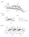
- the forming and the winding of the rubber ribbon can be carried out by using an equipment as exemplified in FIG. 3 .
- This equipment is provided with a rubber ribbon supply apparatus 30 which can form a double-layered rubber ribbon 20 by co-extruding two kinds of rubbers, a rotational support body 31 around which the rubber ribbon 20 supplied from the rubber ribbon supply apparatus 30 is wound, and a control apparatus 32 which carries out an actuation control of the rubber ribbon supply apparatus 30 and the rotational support body 31.
- the rotational support body 31 is structured such that it can rotate in a direction R around an axis 31a and move in an axial direction.
- An extruding machine 33 is provided with a hopper 33a, a screw 33b, a barrel 33c, a drive apparatus 33d of the screw 33b, and a head portion 33e having a gear pump built-in.
- an extruding machine 34 is provided with a hopper 34a, a screw 34b, a barrel 34c, a drive apparatus 34d and a head portion 34e.
- a rubber combining portion 35 additionally provided with a die 36 is provided in leading ends of a pair of extruding machines 33 and 34.
- the respective rubbers are fed out forward while being mixed by the screws 33b and 34b, passed by the head portion 33e and 34e, combined in a predetermined shape at the rubber combining portion 35, and extruded as the double-layered rubber ribbon 20 from a discharge port 36a.
- the formed rubber ribbon 20 is fed out forward by a roll 37, and is wound around the rotational support body 31 while being pressed by a roller 38.
- FIG. 4(A) is a cross sectional view showing the double-layered rubber ribbon 20, and a lower side in FIG. 4 comes to an inner peripheral side which faces to the rotational support body 31 at a time of being wound.
- the rubber ribbon 20 is constructed by a band-like nonconductive rubber portion 21, and a conductive rubber portion 22 which covers at least a part of an outer peripheral surface of the nonconductive rubber portion 21.
- the width 22W of the conductive rubber portion 22 is set, for example, to 75 % to 100 % of a total width 20W of the rubber ribbon 20.
- the cross section of the rubber ribbon 20 is not limited to a triangular shape, but may also be set to other shapes such as a rectangular shape, an oval shape and the like.
- the rubber ribbon made of the nonconductive rubber is spirally wound around an outer peripheral surface of the rotational support body 31 along the tire circumferential direction, thereby forming the base portion 11 as shown in FIG. 5(A) .
- the single-layer rubber ribbon 20' as shown in FIG. 4(B) is spirally wound in an overlapping manner along the tire circumferential direction, thereby forming a position in which the conductive portion 13 of the cap portion 12 is not provided as shown in FIG. 5(B) .
- the double-layered rubber ribbon 20 as shown in FIG. 4(A) is spirally wound in an overlapping manner along the tire circumferential direction, thereby forming a position in which the conductive portion 13 of the cap portion 12 is provided, as shown in FIG. 5(C) .
- one end portion of the conductive rubber portion 22 is connected to a body portion of the adjacent conductive rubber portion 22.
- a portion which the conductive rubber portion 22 exposes to the surface of the tread rubber 10 is formed as the outer skin portion 13a, and the remaining portion of the conductive rubber portion 22 is formed as the projection portion 13b.
- an extrusion forming method is a construction method of extrusion forming an uncured rubber member having a predetermined cross sectional shape and jointing end portions thereof to each other so as to form in an annular shape.
- the outer skin portion 13a At a time of winding the double-layered rubber ribbon 20, it is preferable to terminate the outer skin portion 13a within a region which comes to 5 % to 30 % of the contact width CW from the contact end E toward the inner side in the tire width direction. Further, it is preferable to terminate the projection portion 13b within a range between 15 % and 80 % of the main groove depth D from the surface of the tread rubber 10.
- a green tire is formed by combining the tread rubber 10 with the other tire constructing members such as the carcass layer 7, the side wall rubber 9 and the like, and the pneumatic tire T shown in FIG. 1 can be manufactured by applying a curing treatment to the green tire.
- the rubber ribbon 20 shown in FIG. 8 is used.
- thickness tb of the portion 22b of the conductive rubber portion, which is the projection portion 13b is made larger than thickness ta of the portion 22a of the conductive rubber portion, which is the outer skin portion 13a.
- a mold is pressed on the surface of the tread rubber 10, and a convex portion for forming a lateral groove results in compressing the projection portion 13b.
- a convex portion for forming a lateral groove results in compressing the projection portion 13b.
- thickening the projection portion 13b like this, it is possible to prevent a decoupling of the projection portion 13b to secure an electric conduction performance after the wear, and to prevent cracks of the projection portion 13b to secure a durability performance.
Landscapes
- Engineering & Computer Science (AREA)
- Mechanical Engineering (AREA)
- Tires In General (AREA)
- Tyre Moulding (AREA)
Abstract
Description
- The present invention relates to a pneumatic tire which can discharge static electricity generated in a vehicle body and a tire, to a road surface, and a manufacturing method of such a pneumatic tire.
- Recently, there has been proposed a pneumatic tire including a tread rubber blended with silica at a high ratio in order to reduce the rolling resistance that largely affects a fuel consumption performance. However, compared to a tread rubber blended with carbon black at a high ratio, the electric resistance of such a tread rubber is high, and accordingly, static charges generated on a vehicle body or the tire are prevented from being released to the road surface. As a result, problems like radio noises tend to occur.
- Accordingly, there has been developed a pneumatic tire structured such that a tread rubber constructed by a nonconductive rubber blended with a silica or the like is provided with a conductive portion constructed by a conductive rubber blended with a carbon black or the like, whereby an electric conduction performance can be achieved.
For example, in a pneumatic tire described in the Japanese Unexamined Patent Application PublicationJP-A-2000-190709 - However, in the pneumatic tire as mentioned above, when wear makes progress to such a degree that a surface of the tread rubber disappears by a thickness of the conductive portion, the conductive portion becomes short, a position of a terminal end moves close to a contact end, and the frequency at which the conductive portion comes into contact with a road surface is widely reduced.
Therefore, there has been a tendency that an electric conduction performance is lowered when wear makes progress. On the contrary, there can be considered to employ a strategy of forming a thick conductive portion, however, in the light of enhancing an improving effect by forming the tread rubber by a nonconductive rubber, it is desirable to employ means which can make the volume of the conductive portion as small as possible. - Further, in a pneumatic tire described in the following Japanese Unexamined Patent Application Publication
JP-A-2008-13000
However, in the structure mentioned above, since the conductive route becomes long in distance, there has been a tendency that an electric resistance is increased. In order to well secure the electric conduction performance, it is desirable to employ means which can suppress a long distance of the conductive route at least in an early stage of the wear. - The present invention has been made by taking the actual condition and situation mentioned above into consideration, and an object of the present invention is to provide a pneumatic tire which can well secure an electric conduction performance regardless of the progress degree of wear and can reduce the volume of a conductive portion provided in a tread rubber, and a manufacturing method of producing such a pneumatic tire.
- The object can be achieved by the following invention. That is, the present invention provides a pneumatic tire comprising a tread rubber formed by a nonconductive rubber, a conductive portion formed by a conductive rubber and reaching a side surface of the tread rubber from a contact surface, and the conductive portion being provided in the tread rubber, wherein the conductive portion comprises an outer skin portion which is formed on a surface of the tread rubber, and extends to an inner side in a tire width direction from the side surface of the tread rubber so as to terminate at a position which goes beyond a contact end, and a projection portion which spirally extends along a tire circumferential direction from a position outside of the contact end in the tire width direction so as to reach a position inside of the contact end in the tire width direction, and protrudes to an inner side in a tire diametrical direction from the outer skin portion so as to terminate without reaching a bottom surface of the tread rubber.
- In accordance with the pneumatic tire of the present invention, since the outer skin portion is formed on the surface of the tread rubber in the early stage of the wear, it is possible to inhibit the conductive route from becoming longer in comparison with the conductive portion which is continued as the simple spiral shape, and it is possible to well secure the electric conduction performance.
Further, in the middle stage of the wear, even if the outer skin portion disappears due to the progress of the wear, the conductive route reaching the side surface of the tread rubber from the contact surface is formed via the projection portion.
Accordingly, after all it is possible to well secure the electric conduction performance. In addition, since the outer skin portion and the projection portion are terminated as mentioned above, it is possible to effectively reduce the volume of the conductive portion. - In the pneumatic tire in accordance with the present invention, it is preferable that a terminal end position of the outer skin portion is set within a region which is between 5 % and 30 % of a contact width from the contact end toward the inner side in the tire width direction. Since it is equal to or higher than 5 %, it is possible to secure a frequency at which the outer skin portion comes into contact with the road surface so as to achieve an excellent electric conduction performance. Further, since it is equal to or less than 30 %, it is possible to effectively reduce the volume of the conductive portion without extending the outer skin portion more than necessary.
- In the pneumatic tire in accordance with the present invention, it is preferable that a terminal end position of the projection portion is set within a region which is between 15 % and 80 % of a main groove depth from the surface of the tread rubber. Since it is equal to or higher than 15 %, it is possible to prevent the projection portion from disappearing early due to the progress of the wear so as to well maintain the electric conduction performance after the wear. Further, since it is equal to or less than 80 %, it is possible to effectively reduce the volume of the conductive portion without extending the projection portion more than necessary,
- In the pneumatic tire in accordance with the present invention, it is preferable that the thickness of the projection portion is made larger than the thickness of the outer skin portion. Thereby, it is possible to prevent a decoupling of the projection portion so as to secure an electric conduction performance after the wear, and to prevent cracks of the projection portion so as to secure a durability performance.
- Further, the present invention provides a manufacturing method of a pneumatic tire, the pneumatic tire comprising a tread rubber formed by a nonconductive rubber, a conductive portion formed by a conductive rubber and reaching a side surface of the tread rubber from a contact surface, and the conductive portion being provided in the tread rubber, wherein a step of forming the tread rubber includes a stage of spirally winding in an overlapping manner a rubber ribbon formed by coating at least a part of an outer peripheral surface of a band-like nonconductive rubber portion by a conductive rubber portion, along a tire circumferential direction, and connecting one end portion of the conductive rubber portion to a body portion of the conductive rubber portion which are adjacent to each other, and wherein a portion which the conductive rubber portion exposes to a surface of the tread rubber is set to an outer skin portion which extends to an inner side in a tire width direction from a side surface of the tread rubber so as to terminate at a position going beyond a contact end, and the remaining portion of the conductive rubber portion is set to a projection portion which extends spirally along the tire circumferential direction from a position outside of the contact end in the tire width direction so as to reach a position inside of the contact end in the tire width direction, and protrudes to the inner side in the tire diametrical direction from the outer skin portion so as to terminate without reaching a bottom surface of the tread rubber.
- In accordance with the manufacturing method of the pneumatic tire of the present invention, it is possible to easily and effectively form the conductive portion of the pneumatic tire in accordance with the present invention mentioned above, by spirally winding the rubber ribbon as mentioned above.
The manufactured pneumatic tire can inhibit the conductive route from becoming longer by the outer skin portion so as to well secure the electric conduction performance in the early stage of the wear, and can well secure the electric conduction performance by the projection portion in the stage that the outer skin portion disappears by the progress of the wear. In addition, since the outer skin portion and the projection portion are terminated as mentioned above, it is possible to effectively reduce the volume of the conductive portion. - In the manufacturing method of the pneumatic tire in accordance with the present invention, it is preferable that the outer skin portion is terminated within a region which is between 5 % and 30 % of a contact width from the contact end toward the inner side in the tire width direction.
Since it is equal to or higher than 5 %, it is possible to secure a frequency at which the outer skin portion comes into contact with the road surface so as to achieve an excellent electric conduction performance. Further, since it is equal to or less than 30 %, it is possible to effectively reduce the volume of the conductive portion without extending the outer skin portion more than necessary. - In the manufacturing method of the pneumatic tire in accordance with the present invention, it is preferable that the projection portion is terminated within a region which is between 15 % and 80 % of a main groove depth from the surface of the tread rubber.
Since it is equal to or higher than 15 %, it is possible to prevent the projection portion from disappearing early due to the progress of the wear so as to well maintain the electric conduction performance after the wear. Further, since it is equal to or less than 80 %, it is possible to effectively reduce the volume of the conductive portion without extending the projection portion more than necessary. - In the manufacturing method of the pneumatic tire in accordance with the present invention, it is preferable that the thickness of the portion of the conductive rubber portion which is the projection portion is made larger than the thickness of the portion of the conductive rubber portion which is the outer skin portion.
Thereby, it is possible to prevent a decoupling of the projection portion so as to secure an electric conduction performance after the wear, and to prevent cracks of the projection portion so as to secure a durability performance. -
- FIG. 1
- is a cross sectional view of a tire meridian showing one example of a pneumatic tire according to the present invention;
- FIG. 2
- is an enlarged view showing a substantial part of the tire in
FIG. 1 ; - FIG. 3
- is a view of an outline structure of an equipment for carrying out a winding of a rubber ribbon;
- Figs. 4(A) and 4(B)
- are cross sectional views showing one example of the rubber ribbon which is used for forming a tread rubber;
- Figs. 5(A) to 5(C)
- are cross sectional views schematically showing a forming step of the tread rubber;
- FIG. 6
- is a cross sectional view schematically showing the winding of the rubber ribbon;
- FIG. 7
- is a cross sectional view showing a substantial part of the tread rubber in another embodiment in the present invention;
- FIG. 8(A) and 8(B)
- are cross sectional views showing one example of a rubber ribbon which is used for forming the tread rubber of
FIG.7 ; and - FIG. 9
- is a cross sectional view schematically showing the winding of the rubber ribbon of
FIG. 8 . - An embodiment of the present invention will be explained with reference to the drawings. A pneumatic tire T shown in
FIG. 1 includes a pair ofbead portions 1,side wall portions 2 extending from thebead portions 1 to outer side in a tire diametrical direction, atread portion 3 connected to outer ends in a tire diametrical direction of theside wall portions 2. Thebead portion 1 includes anannular bead 1a composed of a bundle of steel wires or the like sheathed with rubber and abead filler 1b of hard rubber disposed therein. - A toroid-shaped carcass layer 7 is arranged between the pair of
bead portions 1, and an end portion thereof is fixed via thebead 1a being wound thereon. The carcass layer 7 is constructed by at least one (two in the present embodiment) carcass plies, and the carcass ply is formed by covering a cord extending at an angle of approximately 90° with respect to the tire equator C with a topping rubber. The carcass layer 7 is provided with an inner liner rubber 5 for maintaining air pressure on the inner periphery thereof. - The
bead portion 1 of the carcass layer 7 is provided with a rim strip rubber 4 on the outer periphery thereof, which abuts on a rim (not shown). Also, thesidewall portion 2 of the carcass layer 7 is provided with aside wall rubber 9 on the outer periphery thereof. According to the embodiment, the rim strip rubber 4 and theside wall rubber 9 are formed of conductive rubber respectively. - A belt layer 6 constructed by a plurality of (two in the present embodiment) belt plies is arranged on an outer periphery of the carcass layer 7 in the
tread portion 3. Each of the belt plies is formed by covering a cord extending while being inclined with respect to the tire equator C with a topping rubber, and is laminated in such a manner that the cord intersects inversely to each other between the plies. A belt reinforcing layer 8 constructed by covering a cord extending substantially in a tire circumferential direction with a topping rubber is arranged in an outer periphery of the belt layer 6, however, it may be omitted as occasion demands. - A
tread rubber 10 formed by a nonconductive rubber is arranged in thetread portion 3, and thetread rubber 10 is provided with aconductive portion 13 which is formed by a conductive rubber and reaches a side surface of thetread rubber 10 from a contact surface. Thetread rubber 10 in accordance with the present embodiment is provided with acap portion 12 which is formed by a nonconductive rubber and constructs the contact surface, and abase portion 11 which is formed by a nonconductive rubber and is joined to an inner side in a tire diametrical direction of thecap portion 12. A plurality ofmain grooves 15 extending along a tire circumferential direction are formed in a surface of thetread rubber 10. - The conductive rubber makes use of a rubber in which a specific volume resistance is less than 108 Ohm·cm, and is produced, for example, by blending a carbon black serving as a reinforcing agent in a raw material rubber at a high ratio.
The conductive rubber can be obtained by blending a predetermined amount of known conductivity applying material such as a carbon including a carbon fiber, a graphite and the like, or a metal including a metal powder, a metal oxide, a metal flake, a metal fiber and the like in addition to the carbon black.
Further, the nonconductive rubber makes use of a rubber in which a specific volume resistance is equal to or more than 108 Ohm·cm, and is produced, for example, by blending a silica serving as the reinforcing agent in the raw material rubber at a high ratio. - As for the raw material rubber mentioned above, the following substances are exemplified: i.e., natural rubber, styrene-butadiene rubber (SBR), butadiene rubber (BR), isoprene rubber (IR), butyl rubber (IIR) and the like. These materials may be used alone or in combination. The above raw rubber is appropriately blended with a curing agent, a cure accelerator, a plasticizer, an antioxidant and the like.
- It is preferable that the conductive rubber forming the
conductive portion 13 has a composition which satisfies such a relationship that a nitrogen adsorption specific surface area N2SA (m2/g) x compounding amount (mass %) of the carbon black is equal to or more than 1900, preferably equal to or more than 2000, and a dibutyl phthalate oil absorption DBP (ml/100g) x compounding amount (mass %) of the carbon black is equal to or more than 1500, preferably equal to or more than 1700, in the light of enhancing the durability of theconductive portion 13 so as to improve the electric conduction performance. N2SA is determined in conformity with ASTM D3037-89, and DBP is determined in conformity with ASTM D2414-90. - As shown in an enlarged manner in
FIG. 2 , theconductive portion 13 has anouter skin portion 13a and aprojection portion 13b. Theouter skin portion 13a is formed on a surface of thetread rubber 10, and extends to an inner side in a tire width direction from a side surface of thetread rubber 10 so as to be terminated at a position which goes beyond a contact end E.
Theouter skin portion 13a is connected to theside wall rubber 9 which is joined to a side surface of thetread rubber 10, and constructs a conductive route in the early stage of a wear. In other words, static electricity generated in a vehicle body and a tire is discharged to a road surface from the rim via the rim strip rubber 4, theside wall rubber 9, and theouter skin portion 13a of theconductive portion 13. - The
projection portion 13b extends spirally along a tire circumferential direction from a position outside of the contact end E in the tire width direction so as to reach a position inside of the contact end E in the tire width direction, and protrudes to an inner side in a tire diametrical direction from theouter skin portion 13a so as to be terminated without reaching the bottom surface of thetread rubber 10.
In the present embodiment, theprojection portion 13b extending continuously as the spiral shape appears as three beard-like projections in a cross section of a tire meridian circle which is vertical to the tire circumferential direction. At least one beard-like projection mentioned above appears in the outer side in the tire width direction of the contact end E and in the inner side thereof in the tire width direction respectively. - If the wear makes progress to a certain degree from a state shown in
Figs. 1 and2 in which the tire is new, a major part of theouter skin portion 13a disappears, and a terminal end position Pa moves close to the contact end E. In the stage mentioned above, a frequency at which theouter skin portion 13a comes into contact with the road surface is widely reduced, in the case that the load applied to the tire is small, however, in the tire T, it is possible to well secure the electric conduction performance through the conductive route via theprojection portion 13b.
In other words, in the state in which theouter skin portion 13a disappears by the progress of the wear, a conductive route which reaches the side surface of thetread rubber 10 from the contact surface is formed via theprojection portion 13b which appears on the surface of thetread rubber 10. - Since the conductive route by the
projection portion 13b is formed as a spiral shape, however, the leading end of theside wall rubber 9 tends to be grounded in this stage, in comparison with the early stage of the wear, a problem that the conductive route becomes long can be lightened.
Since theside wall rubber 9 comes to the easily grounded by the further progress of the wear, in an end stage of the wear, the electric conduction performance can be secured. Theside wall rubber 9 comes to a state in which a leading end thereof can be grounded on the road surface, at a time of 15 % wear (a state in which 15 % of the main groove depth D wears). - As mentioned above, since the
outer skin portion 13a extends in the tire width direction from theside wall rubber 9 so as to reach within the contact surface in the early stage of the wear, the conductive route is inhibited from becoming longer, in comparison with the conductive portion which is continued as the simple spiral shape, and the electric conduction performance can be well secured.
Further, in the middle stage of the wear, even if theouter skin portion 13a disappears, it is possible to well secure the electric conduction performance through the conductive route via theprojection portion 13b. Therefore, in this tire T, the electric conduction performance can be well secured regardless of the progressing degree of the wear. - Since the
tread rubber 10 is all formed by the nonconductive rubber except theconductive portion 13, the other conductive rubber is not connected to the terminal end position Pa of theouter skin portion 13a and the terminal end position Pb of theprojection portion 13b, and theouter skin portion 13a and theprojection portion 13b are terminated as mentioned above, it is possible to effectively reduce the volume of theconductive portion 13.
As a result, it is possible to well enhance an improving effect by forming thetread rubber 10 by the nonconductive rubber (in the case of being highly blended with the silica, a reducing effect of a rolling resistance and an improving effect of a braking performance on a wet road surface). - In the present embodiment, there is shown an example in which the
conductive portion 13 is provided only in one side in the tire width direction, however, this may also be provided in both sides in the tire width direction. However, in the light of reducing the volume of theconductive portion 13, it is preferable that theconductive portion 13 is provided only in one side in the tire width direction as the present embodiment. - The terminal end position Pa of the
outer skin portion 13a is positioned inside of the contact end E in the tire width direction, that is, is arranged within the contact surface. This contact surface indicates a surface of the tread portion which is grounded on the road surface at a time of assembling in a normal rim, vertically putting the tire on the flat road surface in a state in which a normal internal pressure is charged, and applying a normal load, and an outermost position in the tire axial direction comes to the contact end E.
The normal rim is a rim which is determined per tire by a standard system including a standard on which the tire is based, for example, is a standard rim in JATMA, "Design Rim" in TRA, or "Measuring Rim" in ETRTO. - The normal internal pressure is a pneumatic pressure determined per tire by a standard system including a standard on which the tire is based, and is a maximum pneumatic pressure in JATMA, a maximum value described in Table "TIRE LOAD LIMITS AT VARIOUS COLD INFLATION PRESSURES" in TRA, or "INFLATION PRESSURE" in ETRTO, however, in the case that the tire is for a passenger car, it is set to 180 kPa.
Further, the normal load is a load determined per tire by a standard system including a standard on which the tire is based, and is a maximum load capacity in JATMA, a maximum value described in Table mentioned above in TRA, or "LOAD CAPACITY" in ETRTO, however, in the case that the tire is for a passenger car, it is set to 85 % of a corresponding load to 180 kPa. - It is preferable that the terminal end position Pa of the
outer skin portion 13a is located outside of themain groove 15 in the tire width direction, which is positioned in the outermost side in the tire width direction, in the light of reducing the volume of theconductive portion 13.
Further, it is preferable that the terminal end position Pa is set within a region a, and this region a is a region which comes to 5 % to 30 % of the contact width CW from the contact end E toward the inner side in the tire width direction. The contact width CW is defined as a distance in the tire width direction between the contact ends E and E. - In the present embodiment, the
conductive portion 13 is interposed in the interface between thetread rubber 10 and theside wall rubber 9, and theconductive portion 13 is securely connected to theside wall rubber 9. It is preferable that a width b of a region in which theconductive portion 13 and theside wall rubber 9 overlap is between 50 % and 100 % with respect to a width BW of the interface between thetread rubber 10 and theside wall rubber 9, and it is preferably between 50 % and 80 % in the light of reducing the volume of theconductive portion 13. If theconductive portion 13 is connected to theside wall rubber 9, the width b may be made approximately zero. - The
conductive portion 13 is provided in such a manner as to be connected to the rim or the rubber which can be conductive from the rim, and constructs a conductive path for discharging static electricity to the road surface. In this tire T, it is possible to form any or all of the topping rubber of the carcass ply, the rim strip rubber 4 and theside wall rubber 9 by a nonconductive rubber, and in this case, theconductive portion 13 may be extended to theside wall rubber 9, the rim strip rubber 4 or an outer wall surface of the rim strip rubber 4 coming into contact with the rim. Further, it is possible to form the topping rubber of the belt layer 6 or the belt reinforcing layer 8 by the nonconductive rubber. - It is preferable that the terminal end position Pb of the
projection portion 13b is set within a range between 15 % and 80 % of the main groove width D from the surface of thetread rubber 10. In other words, it is preferable that a depth c from the surface of thetread rubber 10 to the terminal end position Pb is between 15 % and 80 % of the main groove depth D.
Further, the number of theprojection portion 13b (the number of the beard-like projection) appearing in the cross section of the tire meridian circle is exemplified by 2 to 10. A relative position of theprojection portion 13b with respect to the contact end E is defined on the basis of a root of theprojection portion 13b (a connected position to theouter skin portion 13a). - The
outer skin portion 13a is formed thin, and the thickness t thereof is preferably equal to or less than 1 mm, for reducing the volume of theconductive portion 13, and is more preferably equal to or less than 0.5 mm, Further, in order to prevent a disconnection of the conductive route so as to maintain the electric conduction performance, the thickness t is preferably equal to or more than 0.03 mm, and more preferably equal to or more than 0.05 mm. This is applied in the same manner to a thickness of theprojection portion 13b. - In the present embodiment, there is shown the example which employs a side-on tread structure obtained by mounting the end portion of the
side wall rubber 9 on both end portions of thetread rubber 10, however, the invention is not limited to this, but there can be employed a tread-on side structure obtained by mounting the end portion of thetread rubber 10 on the end portion of theside wall rubber 9. In this case, a wing rubber formed by the conductive rubber is joined to the side surface of the tread rubber and the outer skin portion is connected to the wing rubber. - As a preferable embodiment in this tire T, as shown in
FIG. 7 , there can be listed up a structure in which thickness tb of theprojection portion 13b is made larger than the thickness ta of theouter skin portion 13a. Thereby, it is possible to prevent a decoupling of theprojection portion 13b so as to secure the electric conduction performance after the wear, and to prevent cracks of theprojection portion 13b so as to secure a durability performance. Such decoupling or cracks of theprojection portion 13b are caused by processing of forming the tread pattern at the time of cure molding. - That is, in case that a lateral groove extending in the crossing direction with respect to a tire circumferential direction is formed on the
conductive portion 13, a mold pressed on the surface of thetread rubber 10 is provided with a convex portion for forming the lateral groove, and this convex portion results in compressing theprojection portion 13b.
Thereby, if theportion 13b comes to be decoupled, it becomes difficult to secure an electric conduction performance after the wear, and in addition, if theprojection portion 13b is formed thin below the lateral groove, cracks occur due to ozone and the like and the durability performance becomes degraded. - In order to avoid problems like the mentioned above, it is effective to set thickness tb larger than thickness ta, and in that case, it is preferable that thickness ta of the
outer skin portion 13a is 0.03 mm or more, and it is more preferable that thickness ta is 0.05 mm or more. In addition, it is preferable to set thickness tb of theprojection portion 13b to be from 1.5 to 3.0 times as thickness ta. - Next, a description will be given of a method of manufacturing the pneumatic tire T. Since this tire T can be manufactured in the same manner as the conventional tire manufacturing step except the aspect relating to the
tread rubber 10, a description will be given by focusing on a forming step of the tread rubber.
As mentioned below, thetread rubber 10 is formed by a so-called ribbon winding construction method. The ribbon winding construction method is a construction method of spirally winding a rubber ribbon which has a small width and is not cured yet in a tire circumferential direction, and forming a rubber member having a desired cross sectional shape. - The forming and the winding of the rubber ribbon can be carried out by using an equipment as exemplified in
FIG. 3 . This equipment is provided with a rubberribbon supply apparatus 30 which can form a double-layeredrubber ribbon 20 by co-extruding two kinds of rubbers, arotational support body 31 around which therubber ribbon 20 supplied from the rubberribbon supply apparatus 30 is wound, and acontrol apparatus 32 which carries out an actuation control of the rubberribbon supply apparatus 30 and therotational support body 31. Therotational support body 31 is structured such that it can rotate in a direction R around anaxis 31a and move in an axial direction. - An extruding machine 33 is provided with a
hopper 33a, ascrew 33b, abarrel 33c, adrive apparatus 33d of thescrew 33b, and ahead portion 33e having a gear pump built-in. In the same manner, an extrudingmachine 34 is provided with ahopper 34a, ascrew 34b, abarrel 34c, adrive apparatus 34d and ahead portion 34e. Arubber combining portion 35 additionally provided with adie 36 is provided in leading ends of a pair of extrudingmachines 33 and 34. - If the nonconductive rubber corresponding to the rubber material is introduced in the
hopper 33a, and the conductive rubber corresponding to the rubber material is introduced in thehopper 34a, the respective rubbers are fed out forward while being mixed by thescrews head portion rubber combining portion 35, and extruded as the double-layeredrubber ribbon 20 from adischarge port 36a. The formedrubber ribbon 20 is fed out forward by aroll 37, and is wound around therotational support body 31 while being pressed by aroller 38. -
FIG. 4(A) is a cross sectional view showing the double-layeredrubber ribbon 20, and a lower side inFIG. 4 comes to an inner peripheral side which faces to therotational support body 31 at a time of being wound. Therubber ribbon 20 is constructed by a band-likenonconductive rubber portion 21, and aconductive rubber portion 22 which covers at least a part of an outer peripheral surface of thenonconductive rubber portion 21.
Thewidth 22W of theconductive rubber portion 22 is set, for example, to 75 % to 100 % of a total width 20W of therubber ribbon 20. The cross section of therubber ribbon 20 is not limited to a triangular shape, but may also be set to other shapes such as a rectangular shape, an oval shape and the like. - If the extrusion of the conductive rubber is stopped by stopping the rotation of the gear pump within the
head portion 34e, and stopping thescrew 34b if necessary, at a time of extruding therubber ribbon 20, a single-layered rubber ribbon 20' formed only by thenonconductive rubber portion 21 as shown inFIG. 4(B) can be obtained.
The actuation of the gear pumps within thehead portions screws control apparatus 32, and it is possible to freely carry out a switching between a single layer and a double layer of the rubber ribbon. - In the step of forming the
tread rubber 10, the rubber ribbon made of the nonconductive rubber is spirally wound around an outer peripheral surface of therotational support body 31 along the tire circumferential direction, thereby forming thebase portion 11 as shown inFIG. 5(A) .
Next, the single-layer rubber ribbon 20' as shown inFIG. 4(B) is spirally wound in an overlapping manner along the tire circumferential direction, thereby forming a position in which theconductive portion 13 of thecap portion 12 is not provided as shown inFIG. 5(B) . - Subsequently, the double-layered
rubber ribbon 20 as shown inFIG. 4(A) is spirally wound in an overlapping manner along the tire circumferential direction, thereby forming a position in which theconductive portion 13 of thecap portion 12 is provided, as shown inFIG. 5(C) . At this time, as shown inFIG. 6 , one end portion of theconductive rubber portion 22 is connected to a body portion of the adjacentconductive rubber portion 22.
As mentioned above, a portion which theconductive rubber portion 22 exposes to the surface of thetread rubber 10 is formed as theouter skin portion 13a, and the remaining portion of theconductive rubber portion 22 is formed as theprojection portion 13b. - In the structure mentioned above, it is possible to continuously change from a stage in
FIG. 5(B) to a stage inFIG. 5(C) by appropriately switching the rubber ribbon 20' and therubber ribbon 20. Further, the order of them may be reversed. With regard to a formation of thebase portion 11 and a position in which theconductive portion 13 of thecap portion 12 are not provided, an extrusion forming method may be employed.
The extrusion forming method is a construction method of extrusion forming an uncured rubber member having a predetermined cross sectional shape and jointing end portions thereof to each other so as to form in an annular shape. - At a time of winding the double-layered
rubber ribbon 20, it is preferable to terminate theouter skin portion 13a within a region which comes to 5 % to 30 % of the contact width CW from the contact end E toward the inner side in the tire width direction. Further, it is preferable to terminate theprojection portion 13b within a range between 15 % and 80 % of the main groove depth D from the surface of thetread rubber 10. - A description is omitted with respect to
FIG. 5 , however, the belt layer 6 and the belt reinforcing layer 8 are arranged in the inner periphery of thetread rubber 10. A green tire is formed by combining thetread rubber 10 with the other tire constructing members such as the carcass layer 7, theside wall rubber 9 and the like, and the pneumatic tire T shown inFIG. 1 can be manufactured by applying a curing treatment to the green tire. - In case of thickening the
projection portion 13b as shownFIG. 7 , therubber ribbon 20 shown inFIG. 8 is used. In thisrubber ribbon 20, thickness tb of theportion 22b of the conductive rubber portion, which is theprojection portion 13b, is made larger than thickness ta of theportion 22a of the conductive rubber portion, which is theouter skin portion 13a.
By winding this in the same manner ofFIG. 5 and FIG. 6 , theconductive portion 13 is provided with theouter skin portion 13a having a thickness ta and theprojection portion 13b having a thickness tb as shown inFIG. 9 . - At the time of carrying out a curing step of the green tire, a mold is pressed on the surface of the
tread rubber 10, and a convex portion for forming a lateral groove results in compressing theprojection portion 13b. However, by thickening theprojection portion 13b like this, it is possible to prevent a decoupling of theprojection portion 13b to secure an electric conduction performance after the wear, and to prevent cracks of theprojection portion 13b to secure a durability performance. -
- 1 =
- bead portions
- 1a =
- annular bead
- 1b =
- bead filler
- 2 =
- side wall portions
- 3 =
- tread portion
- 4 =
- rim strip rubber
- 5 =
- inner liner rubber
- 6 =
- belt layer
- 7 =
- carcass layer
- 8 =
- belt reinforcing layer
- 9 =
- side wall rubber
- 10 =
- tread rubber
- 11 =
- base portion
- 12 =
- cap portion
- 13 =
- conductive portion
- 13a =
- outer skin portion
- 13b =
- projection portion
- 15 =
- main grooves
- 20 =
- rubber ribbon
- 20W =
- total width of
rubber ribbon 20 - 21 =
- nonconductive rubber portion
- 22 =
- conductive rubber portion
- 22W =
- width of
conductive rubber portion 22 - 30 =
- rubber ribbon supply apparatus
- 31 =
- rotational support body
- 31a =
- axis
- 32 =
- control apparatus
- 33 =
- extruding machine
- 33a =
- hopper
- 33b =
- screw
- 33c =
- barrel
- 33d =
- drive apparatus
- 33e =
- head portion
- 34 =
- extruding machine
- 34a =
- hopper
- 34b =
- screw
- 34c =
- barrel
- 34d =
- drive apparatus
- 34e =
- head portion
- 35 =
- rubber combining portion
- 36 =
- die
- 37 =
- roll
- 38 =
- roller
- T =
- tire
- C =
- equator
- D =
- depth of
main groove 15 - CW =
- contact width
- E =
- contact end
- Pa =
- terminal end position of
outer skin portion 13a - Pb =
- terminal end position of
projection portion 13b
Claims (8)
- A pneumatic tire comprising:- a tread rubber (10) formed by a nonconductive rubber;- a conductive portion (13) formed by a conductive rubber and reaching a side surface of the tread rubber (10) from a contact surface; and- the conductive portion (13) being provided in the tread rubber (10),
wherein the conductive portion (13) comprises:- an outer skin portion (13a) which is formed on a surface of the tread rubber (10), and extends to an inner side in a tire width direction from the side surface of the tread rubber (10) so as to terminate at a position which goes beyond a contact end (E); and- a projection portion (13b) which spirally extends along a tire circumferential direction from a position outside of the contact end (E) in the tire width direction so as to reach a position inside of the contact end (E) in the tire width direction, and protrudes to an inner side in a tire diametrical direction from the outer skin portion (13a) so as to terminate without reaching a bottom surface of the tread rubber (10). - The pneumatic tire according to claim 1,
wherein a terminal end position (Pa) of the outer skin portion (13a) is set within a region which is between 5 % and 30 % of a contact width from the contact end (E) toward the inner side in the tire width direction. - The pneumatic tire according to claim 1 or 2,
wherein a terminal end position (Pb) of the projection portion (13b) is set within a region which is between 15 % and 80 % of a main groove depth (D) from the surface of the tread rubber (10). - The pneumatic tire according to any of claims 1 to 3,
wherein the thickness (tb) of the projection portion (13b) is made larger than the thickness (ta) of the outer skin portion (13a). - A manufacturing method of a pneumatic tire,
the pneumatic tire comprising:- a tread rubber (10) formed by a nonconductive rubber;- a conductive portion (13) formed by a conductive rubber and reaching a side surface of the tread rubber (10) from a contact surface; and- the conductive portion (13) being provided in the tread rubber (10),
wherein a step of forming the tread rubber (10) includes a stage of spirally winding in an overlapping manner a rubber ribbon (20) formed by coating at least a part of an outer peripheral surface of a band-like nonconductive rubber portion (21) by a conductive rubber portion (22), along a tire circumferential direction, and connecting one end portion of the conductive rubber portion (22) to a body portion of the conductive rubber portion (22) which are adjacent to each other, and wherein a portion which the conductive rubber portion (22) exposes to a surface of the tread rubber (10) is set to an outer skin portion (13a) which extends to an inner side in a tire width direction from a side surface of the tread rubber (10) so as to terminate at a position going beyond a contact end (E), and the remaining portion of the conductive rubber portion (22) is set to a projection portion which extends spirally along the tire circumferential direction from a position outside of the contact end (E) in the tire width direction so as to reach a position inside of the contact end (E) in the tire width direction, and protrudes to the inner side in the tire diametrical direction from the outer skin portion (13a) so as to terminate without reaching a bottom surface of the tread rubber (10). - The manufacturing method according to claim 5,
wherein the outer skin portion (13a) is terminated within a region which is between 5 % and 30 % of a contact width from the contact end (E) toward the inner side in the tire width direction. - The manufacturing method according to claim 5 or 6,
wherein the projection portion (13b) is terminated within a region which is between 15 % and 80 % of a main groove depth (D) from the surface of the tread rubber (10). - The manufacturing method according to any of claims 5 to 7,
wherein the thickness (tb) of the portion of the conductive rubber portion (22) which is the projection portion (13b) is made larger than the thickness (ta) of the portion of the conductive rubber portion (22) which is the outer skin portion (13a).
Applications Claiming Priority (2)
| Application Number | Priority Date | Filing Date | Title |
|---|---|---|---|
| JP2010283467 | 2010-12-20 | ||
| JP2011245414A JP5852417B2 (en) | 2010-12-20 | 2011-11-09 | Pneumatic tire and manufacturing method thereof |
Publications (2)
| Publication Number | Publication Date |
|---|---|
| EP2465711A1 true EP2465711A1 (en) | 2012-06-20 |
| EP2465711B1 EP2465711B1 (en) | 2013-11-13 |
Family
ID=45349069
Family Applications (1)
| Application Number | Title | Priority Date | Filing Date |
|---|---|---|---|
| EP11193798.3A Active EP2465711B1 (en) | 2010-12-20 | 2011-12-15 | Pneumatic tire and manufacturing method of the same |
Country Status (4)
| Country | Link |
|---|---|
| US (2) | US8550132B2 (en) |
| EP (1) | EP2465711B1 (en) |
| JP (1) | JP5852417B2 (en) |
| CN (1) | CN102555693B (en) |
Cited By (1)
| Publication number | Priority date | Publication date | Assignee | Title |
|---|---|---|---|---|
| WO2018122754A1 (en) * | 2016-12-29 | 2018-07-05 | Pirelli Tyre S.P.A. | Process for the production of an antistatic tyre for vehicle wheels and antistatic tyre thus obtained |
Families Citing this family (10)
| Publication number | Priority date | Publication date | Assignee | Title |
|---|---|---|---|---|
| JP6046951B2 (en) * | 2012-08-24 | 2016-12-21 | 東洋ゴム工業株式会社 | Pneumatic tire and method for manufacturing pneumatic tire |
| JP6004847B2 (en) * | 2012-09-05 | 2016-10-12 | 東洋ゴム工業株式会社 | Pneumatic tire, method for manufacturing pneumatic tire, and rubber ribbon |
| JP6051072B2 (en) * | 2013-02-22 | 2016-12-21 | 東洋ゴム工業株式会社 | Pneumatic tire |
| JP6117082B2 (en) | 2013-11-21 | 2017-04-19 | 東洋ゴム工業株式会社 | Method and device for applying strip rubber |
| JP6289309B2 (en) * | 2014-08-26 | 2018-03-07 | 東洋ゴム工業株式会社 | Pneumatic tire |
| US11376897B2 (en) | 2016-07-07 | 2022-07-05 | Bridgestone Americas Tire Operations, Llc | Electrical conductive gum strip |
| JP6784604B2 (en) * | 2017-01-10 | 2020-11-11 | Toyo Tire株式会社 | Pneumatic tire manufacturing method and pneumatic tire |
| JP7024477B2 (en) * | 2018-02-13 | 2022-02-24 | 住友ゴム工業株式会社 | Tire manufacturing method and tires |
| JP2020108935A (en) * | 2019-01-07 | 2020-07-16 | Toyo Tire株式会社 | Method for manufacturing tread rubber and pneumatic tire |
| CN113872004B (en) * | 2021-09-07 | 2024-05-10 | 和田工业精密电子(常熟)有限公司 | Metal terminal assembling mechanism of vehicle-mounted connector |
Citations (3)
| Publication number | Priority date | Publication date | Assignee | Title |
|---|---|---|---|---|
| JP2000190709A (en) | 1998-12-25 | 2000-07-11 | Sumitomo Rubber Ind Ltd | Pneumatic tire |
| JP2008013000A (en) | 2006-07-04 | 2008-01-24 | Sumitomo Rubber Ind Ltd | Pneumatic tire and manufacturing method thereof |
| JP2008024096A (en) * | 2006-07-19 | 2008-02-07 | Toyo Tire & Rubber Co Ltd | Pneumatic tire and its production method |
Family Cites Families (7)
| Publication number | Priority date | Publication date | Assignee | Title |
|---|---|---|---|---|
| US6044882A (en) * | 1995-03-07 | 2000-04-04 | The Goodyear Tire & Rubber Company | Tire having silica reinforced rubber tread with outer cap containing carbon black |
| EP0819555B1 (en) * | 1996-07-18 | 2003-06-04 | Bridgestone Corporation | Pneumatic tires |
| JPH11227415A (en) * | 1998-02-12 | 1999-08-24 | Bridgestone Corp | Pneumatic tire and manufacture thereof |
| JP4299811B2 (en) * | 2005-07-01 | 2009-07-22 | 住友ゴム工業株式会社 | Pneumatic tire, method for producing the same, and rubber strip |
| EP1876039B1 (en) | 2006-07-04 | 2012-04-18 | Sumitomo Rubber Industries, Ltd. | Hybrid rubber tape and method for manufacturing pneumatic tire |
| US20080128061A1 (en) * | 2006-12-04 | 2008-06-05 | Aaron Scott Puhala | Pneumatic tire with spiral grooving |
| JP4501119B2 (en) * | 2008-01-08 | 2010-07-14 | 東洋ゴム工業株式会社 | Pneumatic tire and manufacturing method thereof |
-
2011
- 2011-11-09 JP JP2011245414A patent/JP5852417B2/en active Active
- 2011-12-13 US US13/324,106 patent/US8550132B2/en not_active Expired - Fee Related
- 2011-12-15 EP EP11193798.3A patent/EP2465711B1/en active Active
- 2011-12-20 CN CN201110429435.4A patent/CN102555693B/en active Active
-
2013
- 2013-08-27 US US14/011,509 patent/US9579934B2/en active Active
Patent Citations (3)
| Publication number | Priority date | Publication date | Assignee | Title |
|---|---|---|---|---|
| JP2000190709A (en) | 1998-12-25 | 2000-07-11 | Sumitomo Rubber Ind Ltd | Pneumatic tire |
| JP2008013000A (en) | 2006-07-04 | 2008-01-24 | Sumitomo Rubber Ind Ltd | Pneumatic tire and manufacturing method thereof |
| JP2008024096A (en) * | 2006-07-19 | 2008-02-07 | Toyo Tire & Rubber Co Ltd | Pneumatic tire and its production method |
Cited By (1)
| Publication number | Priority date | Publication date | Assignee | Title |
|---|---|---|---|---|
| WO2018122754A1 (en) * | 2016-12-29 | 2018-07-05 | Pirelli Tyre S.P.A. | Process for the production of an antistatic tyre for vehicle wheels and antistatic tyre thus obtained |
Also Published As
| Publication number | Publication date |
|---|---|
| JP2012144241A (en) | 2012-08-02 |
| JP5852417B2 (en) | 2016-02-03 |
| US20130340903A1 (en) | 2013-12-26 |
| EP2465711B1 (en) | 2013-11-13 |
| CN102555693B (en) | 2014-12-10 |
| US8550132B2 (en) | 2013-10-08 |
| US9579934B2 (en) | 2017-02-28 |
| CN102555693A (en) | 2012-07-11 |
| US20120152419A1 (en) | 2012-06-21 |
Similar Documents
| Publication | Publication Date | Title |
|---|---|---|
| EP2465711B1 (en) | Pneumatic tire and manufacturing method of the same | |
| US10086659B2 (en) | Pneumatic tire | |
| US8171966B2 (en) | Pneumatic tire and method for manufacturing the same | |
| US9744814B2 (en) | Pneumatic tire and manufacturing method of pneumatic tire | |
| EP2500188B1 (en) | Pneumatic tire | |
| US9579860B2 (en) | Manufacturing method of pneumatic tire | |
| EP2487051B1 (en) | Pneumatic tire | |
| EP2394826A1 (en) | Pneumatic tire | |
| JP5608587B2 (en) | Pneumatic tire manufacturing method and pneumatic tire | |
| US20080216929A1 (en) | Manufacturing method of pneumatic tire and pneumatic tire | |
| WO2007097104A1 (en) | Pneumatic tire and method of manufacturing pneumatic tire | |
| JP2010222004A (en) | Pneumatic tire and method for manufacturing the same | |
| JP5611861B2 (en) | Pneumatic tire manufacturing method and pneumatic tire | |
| JP5630865B2 (en) | Pneumatic tire and manufacturing method thereof | |
| JP5970179B2 (en) | Pneumatic tire manufacturing method and pneumatic tire | |
| JP5508248B2 (en) | Pneumatic tire and manufacturing method thereof | |
| JP6004847B2 (en) | Pneumatic tire, method for manufacturing pneumatic tire, and rubber ribbon | |
| JP4571664B2 (en) | Pneumatic tire and manufacturing method thereof | |
| JP5508247B2 (en) | Pneumatic tire and manufacturing method thereof |
Legal Events
| Date | Code | Title | Description |
|---|---|---|---|
| PUAI | Public reference made under article 153(3) epc to a published international application that has entered the european phase |
Free format text: ORIGINAL CODE: 0009012 |
|
| AK | Designated contracting states |
Kind code of ref document: A1 Designated state(s): AL AT BE BG CH CY CZ DE DK EE ES FI FR GB GR HR HU IE IS IT LI LT LU LV MC MK MT NL NO PL PT RO RS SE SI SK SM TR |
|
| AX | Request for extension of the european patent |
Extension state: BA ME |
|
| 17P | Request for examination filed |
Effective date: 20120904 |
|
| GRAP | Despatch of communication of intention to grant a patent |
Free format text: ORIGINAL CODE: EPIDOSNIGR1 |
|
| RIC1 | Information provided on ipc code assigned before grant |
Ipc: B60C 19/08 20060101AFI20130416BHEP |
|
| INTG | Intention to grant announced |
Effective date: 20130517 |
|
| GRAS | Grant fee paid |
Free format text: ORIGINAL CODE: EPIDOSNIGR3 |
|
| GRAA | (expected) grant |
Free format text: ORIGINAL CODE: 0009210 |
|
| AK | Designated contracting states |
Kind code of ref document: B1 Designated state(s): AL AT BE BG CH CY CZ DE DK EE ES FI FR GB GR HR HU IE IS IT LI LT LU LV MC MK MT NL NO PL PT RO RS SE SI SK SM TR |
|
| REG | Reference to a national code |
Ref country code: GB Ref legal event code: FG4D |
|
| REG | Reference to a national code |
Ref country code: CH Ref legal event code: EP |
|
| REG | Reference to a national code |
Ref country code: AT Ref legal event code: REF Ref document number: 640410 Country of ref document: AT Kind code of ref document: T Effective date: 20131215 |
|
| REG | Reference to a national code |
Ref country code: IE Ref legal event code: FG4D |
|
| REG | Reference to a national code |
Ref country code: DE Ref legal event code: R096 Ref document number: 602011003699 Country of ref document: DE Effective date: 20140109 |
|
| REG | Reference to a national code |
Ref country code: NL Ref legal event code: VDEP Effective date: 20131113 |
|
| REG | Reference to a national code |
Ref country code: AT Ref legal event code: MK05 Ref document number: 640410 Country of ref document: AT Kind code of ref document: T Effective date: 20131113 |
|
| REG | Reference to a national code |
Ref country code: LT Ref legal event code: MG4D |
|
| PG25 | Lapsed in a contracting state [announced via postgrant information from national office to epo] |
Ref country code: NO Free format text: LAPSE BECAUSE OF FAILURE TO SUBMIT A TRANSLATION OF THE DESCRIPTION OR TO PAY THE FEE WITHIN THE PRESCRIBED TIME-LIMIT Effective date: 20140213 Ref country code: SE Free format text: LAPSE BECAUSE OF FAILURE TO SUBMIT A TRANSLATION OF THE DESCRIPTION OR TO PAY THE FEE WITHIN THE PRESCRIBED TIME-LIMIT Effective date: 20131113 Ref country code: FI Free format text: LAPSE BECAUSE OF FAILURE TO SUBMIT A TRANSLATION OF THE DESCRIPTION OR TO PAY THE FEE WITHIN THE PRESCRIBED TIME-LIMIT Effective date: 20131113 Ref country code: HR Free format text: LAPSE BECAUSE OF FAILURE TO SUBMIT A TRANSLATION OF THE DESCRIPTION OR TO PAY THE FEE WITHIN THE PRESCRIBED TIME-LIMIT Effective date: 20131113 Ref country code: IS Free format text: LAPSE BECAUSE OF FAILURE TO SUBMIT A TRANSLATION OF THE DESCRIPTION OR TO PAY THE FEE WITHIN THE PRESCRIBED TIME-LIMIT Effective date: 20140313 Ref country code: NL Free format text: LAPSE BECAUSE OF FAILURE TO SUBMIT A TRANSLATION OF THE DESCRIPTION OR TO PAY THE FEE WITHIN THE PRESCRIBED TIME-LIMIT Effective date: 20131113 Ref country code: LT Free format text: LAPSE BECAUSE OF FAILURE TO SUBMIT A TRANSLATION OF THE DESCRIPTION OR TO PAY THE FEE WITHIN THE PRESCRIBED TIME-LIMIT Effective date: 20131113 |
|
| PG25 | Lapsed in a contracting state [announced via postgrant information from national office to epo] |
Ref country code: AT Free format text: LAPSE BECAUSE OF FAILURE TO SUBMIT A TRANSLATION OF THE DESCRIPTION OR TO PAY THE FEE WITHIN THE PRESCRIBED TIME-LIMIT Effective date: 20131113 Ref country code: LV Free format text: LAPSE BECAUSE OF FAILURE TO SUBMIT A TRANSLATION OF THE DESCRIPTION OR TO PAY THE FEE WITHIN THE PRESCRIBED TIME-LIMIT Effective date: 20131113 Ref country code: ES Free format text: LAPSE BECAUSE OF FAILURE TO SUBMIT A TRANSLATION OF THE DESCRIPTION OR TO PAY THE FEE WITHIN THE PRESCRIBED TIME-LIMIT Effective date: 20131113 Ref country code: BE Free format text: LAPSE BECAUSE OF FAILURE TO SUBMIT A TRANSLATION OF THE DESCRIPTION OR TO PAY THE FEE WITHIN THE PRESCRIBED TIME-LIMIT Effective date: 20131113 Ref country code: RS Free format text: LAPSE BECAUSE OF FAILURE TO SUBMIT A TRANSLATION OF THE DESCRIPTION OR TO PAY THE FEE WITHIN THE PRESCRIBED TIME-LIMIT Effective date: 20131113 Ref country code: CY Free format text: LAPSE BECAUSE OF FAILURE TO SUBMIT A TRANSLATION OF THE DESCRIPTION OR TO PAY THE FEE WITHIN THE PRESCRIBED TIME-LIMIT Effective date: 20131113 |
|
| PG25 | Lapsed in a contracting state [announced via postgrant information from national office to epo] |
Ref country code: PT Free format text: LAPSE BECAUSE OF FAILURE TO SUBMIT A TRANSLATION OF THE DESCRIPTION OR TO PAY THE FEE WITHIN THE PRESCRIBED TIME-LIMIT Effective date: 20140313 |
|
| PG25 | Lapsed in a contracting state [announced via postgrant information from national office to epo] |
Ref country code: EE Free format text: LAPSE BECAUSE OF FAILURE TO SUBMIT A TRANSLATION OF THE DESCRIPTION OR TO PAY THE FEE WITHIN THE PRESCRIBED TIME-LIMIT Effective date: 20131113 |
|
| REG | Reference to a national code |
Ref country code: DE Ref legal event code: R097 Ref document number: 602011003699 Country of ref document: DE |
|
| PG25 | Lapsed in a contracting state [announced via postgrant information from national office to epo] |
Ref country code: SK Free format text: LAPSE BECAUSE OF FAILURE TO SUBMIT A TRANSLATION OF THE DESCRIPTION OR TO PAY THE FEE WITHIN THE PRESCRIBED TIME-LIMIT Effective date: 20131113 Ref country code: CZ Free format text: LAPSE BECAUSE OF FAILURE TO SUBMIT A TRANSLATION OF THE DESCRIPTION OR TO PAY THE FEE WITHIN THE PRESCRIBED TIME-LIMIT Effective date: 20131113 Ref country code: RO Free format text: LAPSE BECAUSE OF FAILURE TO SUBMIT A TRANSLATION OF THE DESCRIPTION OR TO PAY THE FEE WITHIN THE PRESCRIBED TIME-LIMIT Effective date: 20131113 Ref country code: PL Free format text: LAPSE BECAUSE OF FAILURE TO SUBMIT A TRANSLATION OF THE DESCRIPTION OR TO PAY THE FEE WITHIN THE PRESCRIBED TIME-LIMIT Effective date: 20131113 |
|
| PLBE | No opposition filed within time limit |
Free format text: ORIGINAL CODE: 0009261 |
|
| STAA | Information on the status of an ep patent application or granted ep patent |
Free format text: STATUS: NO OPPOSITION FILED WITHIN TIME LIMIT |
|
| REG | Reference to a national code |
Ref country code: IE Ref legal event code: MM4A |
|
| REG | Reference to a national code |
Ref country code: FR Ref legal event code: ST Effective date: 20140829 |
|
| PG25 | Lapsed in a contracting state [announced via postgrant information from national office to epo] |
Ref country code: DK Free format text: LAPSE BECAUSE OF FAILURE TO SUBMIT A TRANSLATION OF THE DESCRIPTION OR TO PAY THE FEE WITHIN THE PRESCRIBED TIME-LIMIT Effective date: 20131113 |
|
| 26N | No opposition filed |
Effective date: 20140814 |
|
| PG25 | Lapsed in a contracting state [announced via postgrant information from national office to epo] |
Ref country code: IE Free format text: LAPSE BECAUSE OF NON-PAYMENT OF DUE FEES Effective date: 20131215 |
|
| REG | Reference to a national code |
Ref country code: DE Ref legal event code: R097 Ref document number: 602011003699 Country of ref document: DE Effective date: 20140814 |
|
| PG25 | Lapsed in a contracting state [announced via postgrant information from national office to epo] |
Ref country code: FR Free format text: LAPSE BECAUSE OF NON-PAYMENT OF DUE FEES Effective date: 20140113 |
|
| PG25 | Lapsed in a contracting state [announced via postgrant information from national office to epo] |
Ref country code: SI Free format text: LAPSE BECAUSE OF FAILURE TO SUBMIT A TRANSLATION OF THE DESCRIPTION OR TO PAY THE FEE WITHIN THE PRESCRIBED TIME-LIMIT Effective date: 20131113 |
|
| PG25 | Lapsed in a contracting state [announced via postgrant information from national office to epo] |
Ref country code: MC Free format text: LAPSE BECAUSE OF FAILURE TO SUBMIT A TRANSLATION OF THE DESCRIPTION OR TO PAY THE FEE WITHIN THE PRESCRIBED TIME-LIMIT Effective date: 20131113 |
|
| PG25 | Lapsed in a contracting state [announced via postgrant information from national office to epo] |
Ref country code: SM Free format text: LAPSE BECAUSE OF FAILURE TO SUBMIT A TRANSLATION OF THE DESCRIPTION OR TO PAY THE FEE WITHIN THE PRESCRIBED TIME-LIMIT Effective date: 20131113 Ref country code: TR Free format text: LAPSE BECAUSE OF FAILURE TO SUBMIT A TRANSLATION OF THE DESCRIPTION OR TO PAY THE FEE WITHIN THE PRESCRIBED TIME-LIMIT Effective date: 20131113 |
|
| PG25 | Lapsed in a contracting state [announced via postgrant information from national office to epo] |
Ref country code: HU Free format text: LAPSE BECAUSE OF FAILURE TO SUBMIT A TRANSLATION OF THE DESCRIPTION OR TO PAY THE FEE WITHIN THE PRESCRIBED TIME-LIMIT; INVALID AB INITIO Effective date: 20111215 Ref country code: LU Free format text: LAPSE BECAUSE OF NON-PAYMENT OF DUE FEES Effective date: 20131215 Ref country code: BG Free format text: LAPSE BECAUSE OF FAILURE TO SUBMIT A TRANSLATION OF THE DESCRIPTION OR TO PAY THE FEE WITHIN THE PRESCRIBED TIME-LIMIT Effective date: 20131113 Ref country code: MK Free format text: LAPSE BECAUSE OF FAILURE TO SUBMIT A TRANSLATION OF THE DESCRIPTION OR TO PAY THE FEE WITHIN THE PRESCRIBED TIME-LIMIT Effective date: 20131113 |
|
| REG | Reference to a national code |
Ref country code: CH Ref legal event code: PL |
|
| PG25 | Lapsed in a contracting state [announced via postgrant information from national office to epo] |
Ref country code: GR Free format text: LAPSE BECAUSE OF NON-PAYMENT OF DUE FEES Effective date: 20131113 Ref country code: MT Free format text: LAPSE BECAUSE OF FAILURE TO SUBMIT A TRANSLATION OF THE DESCRIPTION OR TO PAY THE FEE WITHIN THE PRESCRIBED TIME-LIMIT Effective date: 20131113 Ref country code: IT Free format text: LAPSE BECAUSE OF FAILURE TO SUBMIT A TRANSLATION OF THE DESCRIPTION OR TO PAY THE FEE WITHIN THE PRESCRIBED TIME-LIMIT Effective date: 20131113 |
|
| PG25 | Lapsed in a contracting state [announced via postgrant information from national office to epo] |
Ref country code: LI Free format text: LAPSE BECAUSE OF NON-PAYMENT OF DUE FEES Effective date: 20141231 Ref country code: CH Free format text: LAPSE BECAUSE OF NON-PAYMENT OF DUE FEES Effective date: 20141231 |
|
| PG25 | Lapsed in a contracting state [announced via postgrant information from national office to epo] |
Ref country code: GR Free format text: LAPSE BECAUSE OF FAILURE TO SUBMIT A TRANSLATION OF THE DESCRIPTION OR TO PAY THE FEE WITHIN THE PRESCRIBED TIME-LIMIT Effective date: 20140214 |
|
| GBPC | Gb: european patent ceased through non-payment of renewal fee |
Effective date: 20151215 |
|
| PG25 | Lapsed in a contracting state [announced via postgrant information from national office to epo] |
Ref country code: GB Free format text: LAPSE BECAUSE OF NON-PAYMENT OF DUE FEES Effective date: 20151215 |
|
| PG25 | Lapsed in a contracting state [announced via postgrant information from national office to epo] |
Ref country code: AL Free format text: LAPSE BECAUSE OF FAILURE TO SUBMIT A TRANSLATION OF THE DESCRIPTION OR TO PAY THE FEE WITHIN THE PRESCRIBED TIME-LIMIT Effective date: 20131113 |
|
| PGFP | Annual fee paid to national office [announced via postgrant information from national office to epo] |
Ref country code: DE Payment date: 20231031 Year of fee payment: 13 |