EP2465651A1 - Device for holding and handling a component and method for producing such a device - Google Patents
Device for holding and handling a component and method for producing such a device Download PDFInfo
- Publication number
- EP2465651A1 EP2465651A1 EP10195030A EP10195030A EP2465651A1 EP 2465651 A1 EP2465651 A1 EP 2465651A1 EP 10195030 A EP10195030 A EP 10195030A EP 10195030 A EP10195030 A EP 10195030A EP 2465651 A1 EP2465651 A1 EP 2465651A1
- Authority
- EP
- European Patent Office
- Prior art keywords
- component
- handling
- handling element
- cable
- movable
- Prior art date
- Legal status (The legal status is an assumption and is not a legal conclusion. Google has not performed a legal analysis and makes no representation as to the accuracy of the status listed.)
- Withdrawn
Links
Images
Classifications
-
- B—PERFORMING OPERATIONS; TRANSPORTING
- B25—HAND TOOLS; PORTABLE POWER-DRIVEN TOOLS; MANIPULATORS
- B25J—MANIPULATORS; CHAMBERS PROVIDED WITH MANIPULATION DEVICES
- B25J15/00—Gripping heads and other end effectors
- B25J15/0052—Gripping heads and other end effectors multiple gripper units or multiple end effectors
Definitions
- the invention relates to a device for receiving and handling a component and a method for producing such a device, and more particularly to a device for receiving and handling a component of an article in its manufacture and a method for producing such a device.
- a gripping tool In the industrial manufacture of an article, such as automobiles, technical equipment, furniture, etc., usually individual components of the object to be manufactured are moved from one place to another, the component pivoted about its axis, and / or for a particular treatment in one
- a gripping tool is currently used in the art that can both support the load of the article and is dimensioned to move the article safely and sufficiently quickly from a home position to a desired other position to hold on to these positions as well.
- Fig. 9 1 shows such a prior art gripping tool 100 having a body 110 with a plurality of gripping arms 120, each having a plurality of gripping fingers 121 at one end thereof.
- the body 110 consists of a plurality of metallic parts 111, which are connected to each other, for example by means of screws, bolts or welded joints. Due to this construction, the gripping tool 100 is very complicated both in dimensioning and in the production and thus expensive. In addition, the gripper tool 100 with a total weight of about 90 kg is relatively heavy.
- Another gripping tool is for example from the DE9104388U1 known.
- gripping tools for the industrial production of objects with gripper arms mentioned in which a gripping or non-gripping of the gripping tool is driven pneumatically, electrically, or by means of vacuum.
- the drive of gripper fingers of a gripper arm by cable (Bowden cable) is known.
- the describes DE 102 34 036 A1 a tubular mast or support which is made substantially of non-metallic composite materials and has a box-like, preferably rectangular, construction.
- the box-like structure has four corner profiles of fiber reinforced plastic (FRP) as corners of the box-like structure. Between each two corner profiles, a plate made of non-metallic composite material is used in each case.
- the composite material has a sandwich construction of two cover plates, which preferably have the same material as the four corner profiles. Between the two cover plates is an intermediate layer of foamed material.
- the interior of the mast is usually an air-filled cavity, which, however, can also be filled with hard foam to stiffen the mast against buckling.
- the object is achieved by a device for receiving and handling a component according to claim 1.
- the device comprises a body of lightweight material and at least one handling element for handling the male and to handling member, wherein the at least one handling element is fixed to the body such that the body and the at least one handling element for supporting the load of the component cooperate.
- the device has at least two handling elements which are fixed to the body so as to cooperate for gripping the component.
- the at least one handling element in each case has a movable part which can be received and handled between an open position in which the handling element can not pick up and handle the component, and a closed position in which the handling element can receive and handle the component. is movable back and forth.
- at least two movable parts of the handling element can cooperate for gripping the component (2a).
- each one movable part of the at least one handling element by means of cable, rod, pneumatic, magnetic and / or electrically between the open and the closed position to be moved back and forth.
- the handling element may have a mark for detecting the position of its movable part.
- the device can also have a drive device mounting device for connection to a drive device for driving the respective one movable part of the at least one
- Comprise handling element between the open and the closed position it is possible for the drive device to be part of the device or to be part of a device which is superordinate to the device. In addition, the device can serve for stationary component mounting.
- the body is a lightweight material block which has at least one cavity or is a solid block.
- the body may have recesses to which the at least one handling element is attached to the body.
- the body is made of rigid foam, balsa wood or hard foam polystyrene.
- the object is also achieved by a method for producing a device for receiving and handling a component according to claim 13.
- the method has the step of fastening a body of lightweight material together and at least one handling element for handling the component to be picked up and handled in such a way that the body and the at least one handling element interact to support the load of the component.
- the method further comprises the steps of: generating at least one cavity in the body; and / or coating the body with a coating to protect the body against environmental influences and / or to increase the rigidity or strength of the body.
- the device described above can be used in the automated handling and in particular the gripping of objects or their components and can thus be used for the manufacture of objects from a plurality of individual components or for their disassembly, etc.
- the device is very user-friendly, since there are advantages in their design, manufacture, installation, commissioning, maintenance / disassembly. That is, the device is significantly easier to design and manufacture and consists of significantly less expensive components than a prior art device.
- the changeover times of a system equipped with the device described in various gripping tasks and thus reduce the downtime of the system.
- the quality of handling and thus of an ultimately manufactured article is improved.
- the device according to the invention also makes effective use of a high potential for savings in terms of time and money compared with the prior art.
- the life cycle assessment of the device according to the invention is significantly improved by the lower use of raw materials, the simplified and environmentally sound disposal of the device, as well as the reduced drive requirement due to the reduction in weight compared to the prior art.
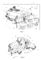
- Fig. 1 schematically shows a plant 1 for the production of at least one article 2, the in Fig. 1 is shown schematically as a motor vehicle on a smaller scale, and consists of several identical or different components 2a, such as the in Fig. 1 shown metal automotive body part.
- the article 2 may for example also be a truck, an audio device, etc., so that the component 2a is one of its individual parts.
- the system 1 has a device 10 for receiving and handling the component 2 a in the production of the article 2 and a drive device 30 for driving the device 10.
- the device 10 comprises a body 11 having recesses 11a, with an in Fig. 1 only indicated coating 11b is provided and a plurality of or a plurality of cavities 12 and surrounding webs 13 has, and the recesses 11a a plurality of handling elements 14 which are connected to the body 11 and at one end of a movable part 15, the between an open position A, the in Fig. 2A is shown, and a closed position B, in Fig. 2B is shown, can be moved back and forth.
- the body 11 has two centering pins 14a, which can engage in not shown centering points of the component 2a, when the component 2a is aligned with the device 10 properly.
- the movable parts 15 do not contact docking parts 16, whereas in the closed position B they contact or touch the docking parts 16.
- the component 2a can be clamped or clamped in the closed position B of the movable parts 15 between the movable part 15 and the docking part 16.
- the movable parts 15 and / or the docking parts 16 may be provided with a coating element, not shown, of foam or rubber, etc. If necessary, the docking part 16 can also be omitted, so that the at least one movable part 15 in its closed position B biases the component 2 a directly to the body 11.
- a component 2a (FIG. Fig. 1 ) are moved and held to transport the component 2a over a certain distance, to pivot in a certain position, etc.
- the movable member 15 is thus on the handling element 14 between at least two positions A, B movable back and forth.
- the device 10 has a drive device mounting device 17, to which the drive device 30 (FIG. Fig. 1 ) of the system 1 for driving the handling elements 14 or their movable parts 15 via at least one of a plurality of line connections 18 can be connected, as in Fig. 1 . Fig. 2A and Fig. 2B shown.
- the line connections 18 are part of a pneumatic or electric drive system, or operate with vacuum or with vacuum force.
- the handling elements 14 and their movable parts 15 act in the in Fig. 1 . Fig. 2A and Fig. 2B shown apparatus 10 preferably as gripping arms with their gripper fingers.
- the body 11 is in Fig. 1 .
- Fig. 2A and Fig. 2B a lightweight block of material in which the cavities 12 are made, for example by drilling or milling, etc., so that webs 13 remain between the cavities 12 and separate the individual cavities 12 from each other.
- the webs 13 are mainly used to stiffen the body 11 against twisting.
- the lightweight material block of the body 11 is preferably made of hard foam, which is marketed under the brand rohacell ® a lightweight material, balsa wood or foam polystyrene, which is also known under the trademark Styrofoam ®, etc .. These materials provide sufficient strength and rigidity to to carry both the weight of the handling elements 14 and the gripped by means of the movable member 15 2a.
- the surface of the body 11 is preferably entirely covered with the coating 11b, which is preferably paintable or sprayable with a brush or spatula, etc., such as a varnish into which the body 11 is also dippable for the purpose of applying the coating 11b is.
- the cover 11b serves to protect the body 11 against environmental influences, such as damage by liquids, gases, shocks, welding spatter, etc., or also to increase the rigidity or strength of the body 11.
- the coating 11b may for example consist of polyurethane / CFRP short fiber. This means that the supporting part of the body 11 is exclusively the foam block. No additional part or enclosure of the body 11 is needed from such additional parts.
- the body 11 may also be provided with a covering of, for example, plastic, which, however, does not have to fulfill a supporting function.
- Fig. 1 are the handling elements 14, their movable parts 15 for supporting the handling elements 14 on the body 11, for example made of metal or plastic, etc. manufactured.
- the material depends on the strength required by the handling elements 14 and their movable parts 15.
- the movable parts 15 may for example also be wholly or partially made of foam, if they have to contact a particularly touch-sensitive component.
- the handling elements 14 and the body 11 are secured together so that at least one handling element 14 is adhered to the body 11.
- the handling elements 14 can be sunk into the body 11 and additionally glued if necessary.
- the handling element 14 may be fastened to the body 11 by means of at least one adapter element, not shown.
- the handling element 14 may be attached to at least one adapter element, for example by means of screws, riveting, welding, soldering, etc., and the at least one adapter element is connected by gluing and / or countersinking with the body 11.
- the handling elements 14 are fixed to the body 11 such that the body 11 and the handling elements 14 cooperate to support the load of the component 2a.
- the load of the component 2a results here from the static or accelerated weight of the component 2a.
- the attachment point between the body 11 and a handling element 14 should thus be able to absorb at least slightly more than the load of this handling element 14 and the load of the component 2 a to be picked up by it.
- either a handling element 14 with its movable part 15 alone can grasp a component 2a by clamping or tensioning the component 2a between the body 11 and the movable part 15.
- at least two handling elements 14 cooperate and together a larger or heavy component 2a, such as a vehicle door, hood, or parts thereof, etc., engage, as in Fig. 1 shown.
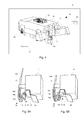
- Fig. 3 shows the device 10 of Fig. 1 in perspective from below.
- further cavities 12a are present in the underside of the body, which are separated from one another by webs 13a and whose cross section is arranged substantially perpendicular to the cross section of the cavities 12.
- the webs 13 and the webs 13a are arranged transversely to each other and are preferably substantially perpendicular to each other.
- the device 100 of the prior art shown which has a total weight of about 90 kg, has the in Fig. 1 to Fig. 3 shown device 10 with the body 11 made of lightweight material only a total weight of about 72 kg. That is, by the body 11 results in the device 10, a weight saving of about 20% over the cited prior art.
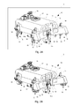
- Fig. 4 1 illustrates a system 3 according to the second embodiment, which also has a device 10 and a drive device 30 and also serves to produce at least one object 2, like the system 1 of the first embodiment.
- the component 2a is in Fig. 4 not shown for simplicity of illustration. Identical and equivalent parts in both embodiments are therefore provided with the same reference numerals and will not be described again here.
- the difference between the first and second embodiments is that the device 10 in the present embodiment, instead of the handling elements 14 with movable parts 15, at least one handling element as a cable pulling element 19 has.
- the cable element 19 may also be referred to as a lightweight tensioner, which may be attached to the body 11, as well as in FIGS. 5A and 5B shown in more detail. That is, the cable pull element 19 has a cable pull element body 19a, a cable pull 19b, preferably provided with a protective sleeve S, which is connected to the drive device mounting device 17 of FIG Fig. 4 is connected, a movable member 19c and a pivot axis 19d, about which the movable member 19c on the cable pulling element body 19a is pivotally or movable.
- the component 2a is provided at possible contact points 2b with the cable pull element 19 with protective bodies, not shown, in order to protect the component 2a from damage.
- the protective bodies are made of foam or rubber, etc., for example. Depending on requirements, the protective body can also be omitted. It is also possible that the protective bodies are attached to the body 11 so as to be disposed between the component 2a and the body 11. *** " The protective bodies can also be arranged as a steel part, for example a steel plate, on the movable part, so that a direct guidance to the component 2a can be transmitted with the movable part 19c via the protective body.
- the protective body can also be made as a bead of, for example, polyurethane.
- the cable pull element body 19a is attached to the body 11 by means of adhesion or countersinking and possibly additional gluing or by means of adapter elements (n), as described in the first exemplary embodiment.
- the movable part 19c is in the form of a clamping jaw and serves to contact the component 2a and to clamp the component 2a to the body 11. More specifically, the movable part 19c is moved between an open position A by means of the cable 19b driven by the drive means 30, in the Fig. 5A is shown, and a closed position B, in Fig. 5B shown is moved back and forth. In Fig. 5A the movable part 19c does not contact the component 2a, the cable 19b being pulled upwards by the drive means 30. In contrast, contacted in Fig.
- the cable 19b is not pulled by the drive means 30 but acts as a push rod. More specifically, the cable 19b of the cable pulling element 19 is pushed back and forth between the open position A and the closed position B as a rod. The cable 19b acts or is therefore a rod. If the cable 19b is designed as a cable pull and not as a rod, the protective cover S is preferably designed such that the cable 19b can not buckle during its movement.
- the protective cover S may be a metal sleeve, for example a wire tube.
- a marking can be provided on the cable pull element 19 which is optically detected, for example, by an optical detection device, not shown, so that the actual state of the cable element 19 can be monitored.
- the bolt 19e vertically reciprocated by the cable 19b in a slot of the cable pulling member body 19a may serve as such a mark.
- the device 10 of this embodiment has no drive means, but only a drive means mounting means 17 to which the central drive means 30 of the system 1 can be connected to the device 10 for all cable pull elements 19.
- the drive device mounting device 17 is shown enlarged.
- the drive device mounting device 17 has a first guide column 17 a and a second guide column 17 b on a mounting plate 17 c, which are arranged lying on the device 10.
- the guide columns 17a and 17b guide a cable carriage 19f.
- the drive device 30 can be connected to the cable pull slide 19f.
- To a docking 19h the plant 1 or one of its robots, not shown, can be attached.
- the drive device drive element of the drive device 30 unlocks the cable traction carriage 19f during coupling.
- Several cables 19b can be actuated by several cable pull elements 19 via these.
- a component 2a with a plurality of movable parts 19c can be clamped to the body 11 at the same time. That is, it is a plurality of cables of the cable pull elements 19 coupled together and actuated on the device 10 by the cable carriage 19f (displacement unit).
- the plurality of cables 19b and the cables 19b may also be operated individually.
- the detection device not shown, can also detect the position of the Seilzugschlittens 19f or markings on the guide columns 17a, 17b, so that here, the actual state of the cable element 19 can be monitored.
- the device 10 of this embodiment thus has no pneumatic or electrical. This means that the one or more cable pull elements 19 is / are remotely controlled.
- the device 100 of the prior art shown which has a total weight of about 90 kg, has the in Fig. 4 to Fig. 6 shown device 10 with the body 11 made of lightweight material and the cable elements 19 instead of the gripping arms 14, gripper fingers 15 and struts 16 only a total weight of about 45 kg. That is, by the body 11 and the aforementioned cable pull elements 19 and displacement of the drive device 30 to the system 1 results in the device 10 of this embodiment, a weight saving of about 50% compared to the cited prior art.
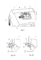
- FIGS. 7A and 7B represent a first variant of the cable element 19 of the second embodiment, which in FIGS. 5A and 5B is shown. More precisely, it is in FIGS. 7A and 7B in each case a cable pull element 20 is shown, which has a cable pull element body 20a, a Bowden cable or cable pull 20b, which is connected to the drive device mounting device 17 of FIG Fig. 4 connectable and surrounded with a protective cover S, a movable member 20c, a pivot axis 20d and a rod 20e has. That is to say, the cable pull 20b has an inflexible pull-push rod (20e) in the end region of its inner wire drawing element.
- the rod 20e is coupled to the cable 20b such that the movable member 20c on the cable member body 20a is pivotable about the pivot axis 20d.
- the movement of the movable part 20c takes place in the cable pull element 20 in the same way as in the cable pull element 19 between an open and a closed position A, B or between a contactless position and a contact position.
- Fig. 7A the movable part 20c does not contact the component 2a, wherein the flexible cable pull 20b does not pull against the rod 20e, ie is not pulled by the drive device 30 or the cable pull slide 19e.
- the rod 20e is thus in the in Fig. 7A shown position pushed down.
- the movable part 20c is in Fig. 7A in the open position A.
- the movable part 20c clamps the component 2a and clamps the component 2a between itself and the body 11, the cable pull 20b being pulled upwards by the drive device 30 or the cable pull slide 19e.
- the movable member 20c is upwardly in through the thrust action of the rod 20e Fig. 7B in the closed position B.
- the cable 20b pushes the rod 20e in Fig. 7A while he's at Fig. 7B the pole 20e pulls.
- the weight saving for the device 10 of about 50% over the cited prior art is given.
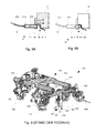
- FIGS. 5A and 5B represent a second variant of the cable element 19 of the second embodiment, which in FIGS. 5A and 5B is shown. More precisely, Fig. 8A shows a cable pull element 21 in a three-dimensional sectional view, whereas Fig. 8B shows the cable pull element 21 in a three-dimensional side view.
- the cable pull element 21 has in each case a cable pull element body 21a, a Bowden cable or cable pull 21b surrounded by a protective sleeve S and connected to the drive device 17 of FIG Fig. 4 is connectable, a movable part 21c in the form of a cylindrical piston and two fixing pins 21d.
- the cable pull element body 21a is fastened to the body 11 of the device 10 by means of the two fastening pins 21d or anchored in the body 11, as shown Fig. 8A seen.
- a bonding of the two fixing pins 21d to the body 11 and / or a gluing of cable pull body 21a and body 11 is possible, if necessary.
- Movement of the movable part 21c also takes place in the cable pull element 21, as in the cable pull element 19, between an open and a closed position A, B, or between a contactless position and a contact position.
- the movable part 21c is pushed back and forth in the cable pull body 21a.
- the cable pull element body 21a has for this purpose a cylindrical sleeve in which the movable part 21c is enclosed and guided.
- the movable part 21c does not contact the component 2a, wherein the cable pull 21b is pulled upwards by the drive device 30 or the cable pull slide 19e, ie is tensioned.
- the movable part 21c is in Fig. 8A in the open position A.
- Fig. 8A in the open position A.
- a mark M On the movable part 21c is a mark M, which is visible when the movable part 21c of the cable pull element 21 is closed in a window F of the cable pull element body 21a, as seen in FIG Fig. 8B seen.
- the mark M with the movable part 21c open the Seilzugelements 21 in the window F of Seilzugelement stressess 21 a not visible, as from Fig. 8A seen.
- the cable pull element 21 or the handling element thus has a marking M, which serves to detect the position of its movable part 21c and can be detected with an optical detection device.
- the weight saving for the device 10 of about 50% over the cited prior art is given.
- the device 10 in the foregoing description is part of a system 1 or 3 and is controlled by this system 1 or 3, that is a robot-guided element, the device 10 can also act only as a stationary component recording.
- the drive device 30 is not part of the system 1 or 3 but is part of the device 10 itself.
- the body 11 may either be cut from a single block of lightweight material or may consist of a plurality of lightweight block or parts secured together, for example by gluing, optionally also by welding, etc.
- these may be two layers of lightweight block material, as shown in FIG Fig. 3 it can be seen that one lightweight block of material layer has the cavities 12 and the lands 13 therebetween, while the other lightweight material block layer has the cavities 12a and the lands 13a therebetween.
- the body 11 is made of foam, it can also be made in a mold, possibly also with cavities 12 or 12a, into which foam is extruded.
- the body 11 is manufactured with the molding tool as an optimized solid body. That is, the solid has no cavities 12 or 12a and is optimized in terms of its outer contour, since it already has the final shape. More specifically, in this case, the external shape of the body 11 need no longer be machined by means of a tool such as a wire.
- the body 11, with its cavities 12, 12a and webs 13, 13a, is a lightweight material block skeleton, which is supported by partial reinforcements, or stringer, For example, from chipboard (s), can be further stabilized.
- the cavities 12, 12a may be the same or different sizes, or long, wide and high.
- the webs 13, 13a may be the same or different sizes, or long, wide and high.
- the body 11 need not have any of the cavities 12, 12a, and thus may also be a solid block without cavities 12, 12a.
- the body 11 may also have only one cavity, which may be a cavity 12 or a cavity 12a.
- the number of cavities 12, 12a is therefore arbitrary.
- the arrangement and dimension of the cavity / cavities 12, 12 a in the body 11 is arbitrary.
- the cavities 12, 12a in addition to the square shape shown in the figures, can also be triangular, rectangular, pentagonal, etc., or round, oval, etc., that is, arbitrarily shaped.
- the cavities 12, 12a can be closed by cover plates in the outer circumferential region, wherein the cover plates can preferably consist of the same material as the body 11 and, for example, can be glued.
- the outer shape of the body 11 is arbitrary and not limited to the representation shown in the figures. That is, the handling elements 14 can be attached and / or attached as needed to depressions 11a or bulges of the body 11, not shown.
- a handling element 14 may also have a plurality of movable parts 15, which together grip a component 2a. That is, in this case, at least two handling members 14 do not necessarily cooperate to grip together a larger component 2a, such as a vehicle door, bonnet, or parts thereof, and so on. But in turn, two handling elements 14 can interact, each having a plurality of movable parts 15, or in which only one handling element 14 has a plurality of movable parts 15, whereas the other has only one movable part 15. In this case, it is also possible for the movable parts 15 of the handling elements 14 to contact the component 2 a, while the body 11 and also the remaining parts of the handling elements 14 do not touch the component 2 a.
- the cable pull elements 19 to 21 of the second embodiment can be selected as needed. That is, on the one hand, a combination of these cable pull elements 19 to 21 on the device 10 is possible. On the other hand, it is also possible to use only one or two of the cable pull elements 19 to 21.
- the device 10, in addition to one or more Seilzugierin 19 to 21 and one or more handling elements 14 with movable part 15 and optionally docking 16 have.
- the docking part 16 may be designed as a holding element and, for example, be a mechanical vacuum holder.
- the device 10 may also comprise any combination of different handling elements 14, 19, 20, 21, depending on what component 2a is to be handled. Consequently, the drive device 30 is to be interpreted.
Abstract
Description
Die Erfindung bezieht sich auf eine Vorrichtung zur Aufnahme und Handhabung eines Bauteils und ein Verfahren zum Herstellen einer solchen Vorrichtung, und insbesondere auf eine Vorrichtung zur Aufnahme und Handhabung eines Bauteils eines Gegenstands bei dessen Fertigung und ein Verfahren zum Herstellen einer solchen Vorrichtung.The invention relates to a device for receiving and handling a component and a method for producing such a device, and more particularly to a device for receiving and handling a component of an article in its manufacture and a method for producing such a device.
Bei der industriellen Fertigung eines Gegenstands, wie beispielsweise Kraftfahrzeugen, technischen Anlagen, Möbeln, usw., werden üblicherweise einzelne Bauteile des zu fertigenden Gegenstands von einem Ort zum anderen bewegt, das Bauteil um seine Achse geschwenkt, und/oder für eine bestimmte Behandlungsweise in einer speziellen Position gehalten, usw. Hierzu wird derzeit im Stand der Technik ein Greifwerkzeug verwendet, das sowohl die Last des Gegenstands tragen kann als auch ausreichend dimensioniert ist, um den Gegenstand sicher und ausreichend schnell von einer Ausgangsposition in eine gewünschte andere Position zu bewegen und ihn an diesen Positionen auch zu halten.In the industrial manufacture of an article, such as automobiles, technical equipment, furniture, etc., usually individual components of the object to be manufactured are moved from one place to another, the component pivoted about its axis, and / or for a particular treatment in one In this regard, a gripping tool is currently used in the art that can both support the load of the article and is dimensioned to move the article safely and sufficiently quickly from a home position to a desired other position to hold on to these positions as well.
Dadurch ist wiederum eine Anlage, in die das Greifwerkzeug 100 integriert ist, für ein große Traglast auszulegen und die benötigte Antriebskraft zum Antrieb eines solchen Greifwerkzeugs 100 ist relativ hoch. Außerdem ist eine Umrüstung der Anlage zwischen verschiedenen Greifwerkzeugen 100, die jeweils für spezielle Greifaufgaben gestaltet sind, vergleichsweise zeitaufwändig, was zu hohen Anlagenstillstandzeiten führt.As a result, in turn, a system in which the
Ein weiteres Greifwerkzeug ist beispielsweise aus der
Ferner beschreibt die
Es ist daher Aufgabe der Erfindung, eine Vorrichtung zur Aufnahme und Handhabung eines Bauteils und ein Verfahren zum Herstellen einer solchen Vorrichtung zur Verfügung zu stellen, welche die zuvor genannten Probleme des Standes der Technik lösen.It is therefore an object of the invention to provide a device for receiving and handling a component and a method for producing such a device, which solve the aforementioned problems of the prior art.
Die Aufgabe wird durch eine Vorrichtung zur Aufnahme und Handhabung eines Bauteils nach Patentanspruch 1 gelöst. Die Vorrichtung umfasst einen Körper aus Leichtbauwerkstoff und mindestens ein Handhabungselement zum Handhaben des aufzunehmenden und zu handhabenden Bauteils, wobei das mindestens eine Handhabungselement derart an dem Körper befestigt ist, dass der Körper und das mindestens eine Handhabungselement zum Tragen der Last des Bauteils zusammenwirken.The object is achieved by a device for receiving and handling a component according to
Vorteilhafte weitere Ausgestaltungen der Vorrichtung sind in den abhängigen Patentansprüchen angegeben.Advantageous further embodiments of the device are specified in the dependent claims.
Vorzugsweise hat die Vorrichtung mindestens zwei Handhabungselemente, die derart an dem Körper befestigt sind, dass sie zum Greifen des Bauteils zusammenwirken.Preferably, the device has at least two handling elements which are fixed to the body so as to cooperate for gripping the component.
Es ist von Vorteil, wenn das mindestens eine Handhabungselement jeweils ein bewegbares Teil aufweist, das zwischen einer geöffneten Stellung, in welcher das Handhabungselement das Bauteil nicht aufnehmen und handhaben kann, und einer geschlossenen Stellung, in welcher das Handhabungselement das Bauteil aufnehmen und handhaben kann, hin und her bewegbar ist. Hierbei können mindestens zwei bewegbare Teile des Handhabungselements zum Greifen des Bauteils (2a) zusammenwirken. Ferner kann das jeweils eine bewegbare Teil des mindestens einen Handhabungselements mittels Seilzug, Stange, pneumatisch, magnetisch und/oder elektrisch zwischen der geöffneten und der geschlossenen Stellung hin und her bewegbar sein.It is advantageous if the at least one handling element in each case has a movable part which can be received and handled between an open position in which the handling element can not pick up and handle the component, and a closed position in which the handling element can receive and handle the component. is movable back and forth. In this case, at least two movable parts of the handling element can cooperate for gripping the component (2a). Furthermore, each one movable part of the at least one handling element by means of cable, rod, pneumatic, magnetic and / or electrically between the open and the closed position to be moved back and forth.
Das Handhabungselement kann eine Markierung zur Erfassung der Stellung seines bewegbaren Teils aufweisen.The handling element may have a mark for detecting the position of its movable part.
Die Vorrichtung kann zudem eine Antriebseinrichtung-Montageeinrichtung zum Anschluss an eine Antriebseinrichtung zum Antrieb des jeweils einen bewegbaren Teils des mindestens einenThe device can also have a drive device mounting device for connection to a drive device for driving the respective one movable part of the at least one
Handhabungselements zwischen der geöffneten und der geschlossenen Stellung umfassen. Hierbei ist es möglich, dass die Antriebseinrichtung Teil der Vorrichtung ist oder Teil einer der Vorrichtung übergeordneten Anlage ist. Zudem kann die Vorrichtung zur stationären Bauteilaufnahme dienen.Comprise handling element between the open and the closed position. In this case, it is possible for the drive device to be part of the device or to be part of a device which is superordinate to the device. In addition, the device can serve for stationary component mounting.
Gemäß einer bevorzugten Möglichkeit ist der Körper ein Leichtbauwerkstoffblock , der mindestens einen Hohlraum aufweist oder ein Vollblock ist.According to a preferred possibility, the body is a lightweight material block which has at least one cavity or is a solid block.
Der Körper kann Vertiefungen aufweisen, an welchen das mindestens eine Handhabungselement an dem Körper befestigt ist.The body may have recesses to which the at least one handling element is attached to the body.
Vorzugsweise ist der Körper aus Hartschaumstoff, Balsaholz oder Hartschaumpolystyrol gefertigt.Preferably, the body is made of rigid foam, balsa wood or hard foam polystyrene.
Die Aufgabe wird zudem durch ein Verfahren zum Herstellen einer Vorrichtung zur Aufnahme und Handhabung eines Bauteils nach Patentanspruch 13 gelöst. Das Verfahren hat den Schritt: aneinander Befestigen eines Körpers aus Leichtbauwerkstoff und mindestens eines Handhabungselements zum Handhaben des aufzunehmenden und zu handhabenden Bauteils derart, dass der Körper und das mindestens eine Handhabungselement zum Tragen der Last des Bauteils zusammenwirken.The object is also achieved by a method for producing a device for receiving and handling a component according to
Vorzugsweise hat das Verfahren zudem die Schritte: Erzeugen mindestens eines Hohlraums in dem Körper; und/oder Überziehen des Körpers mit einem Überzug zum Schutz des Körpers gegen Umwelteinflüsse und/oder zur Erhöhung der Steifigkeit oder Festigkeit des Körpers.Preferably, the method further comprises the steps of: generating at least one cavity in the body; and / or coating the body with a coating to protect the body against environmental influences and / or to increase the rigidity or strength of the body.
Die zuvor beschriebene Vorrichtung kann bei dem automatisierten Handhaben und insbesondere dem Greifen von Gegenständen oder ihrer Bauteile zum Einsatz kommen und kann somit zur Fertigung von Gegenständen aus mehreren einzelnen Bauteilen oder auch zu deren Demontage usw. Verwendung finden. Die Vorrichtung ist dabei sehr anwenderfreundlich, da sich Vorteile bei ihrer Konstruktion, Fertigung, Montage, Inbetriebnahme, Wartung / Instandhaltung und Demontage ergeben. Das heißt, die Vorrichtung ist deutlich einfacher zu entwickeln und herzustellen und besteht aus erheblich kostengünstigeren Komponenten als eine Vorrichtung des Standes der Technik.The device described above can be used in the automated handling and in particular the gripping of objects or their components and can thus be used for the manufacture of objects from a plurality of individual components or for their disassembly, etc. The device is very user-friendly, since there are advantages in their design, manufacture, installation, commissioning, maintenance / disassembly. That is, the device is significantly easier to design and manufacture and consists of significantly less expensive components than a prior art device.
Zudem vermindern sich die Umrüstzeiten einer mit der beschriebenen Vorrichtung ausgestatteten Anlage bei verschiedenen Greifaufgaben und somit die Stillstandszeiten der Anlage. Außerdem ist die Qualität der Handhabung und somit eines letztendlich hergestellten Gegenstands verbessert. Auch dadurch ist also mit der erfindungsgemäßen Vorrichtung hohes Einsparpotential in Bezug auf Zeit und Geld im Vergleich zum bisherigen Stand der Technik wirkungsvoll genutzt.In addition, the changeover times of a system equipped with the device described in various gripping tasks and thus reduce the downtime of the system. In addition, the quality of handling and thus of an ultimately manufactured article is improved. As a result, the device according to the invention also makes effective use of a high potential for savings in terms of time and money compared with the prior art.
Darüber hinaus ist die Ökobilanz der erfindungsgemäßen Vorrichtung durch den geringeren Einsatz von Grundstoffen, die vereinfachte und umweltverträgliche Entsorgung der Vorrichtung, sowie den durch die Verminderung des Gewichts bedingten geringeren Antriebsbedarf gegenüber dem Stand der Technik deutlich verbessert.In addition, the life cycle assessment of the device according to the invention is significantly improved by the lower use of raw materials, the simplified and environmentally sound disposal of the device, as well as the reduced drive requirement due to the reduction in weight compared to the prior art.
Nachfolgend ist die Erfindung unter Bezugnahme auf die beiliegende Zeichnung und anhand von Ausführungsbeispielen näher beschrieben. Es zeigen:
-
Fig. 1 eine dreidimensionale Ansicht einer Vorrichtung gemäß einem ersten Ausführungsbeispiel der vorliegenden Erfindung; -
Fig. 2A und Fig. 2B jeweils eine geöffnete und geschlossene Stellung eines bewegbaren Teils eines Handhabungselements der inFig. 1 gezeigten Vorrichtung; -
Fig. 3 eine dreidimensionale Untersicht unter die inFig. 1 ,Fig. 2A und Fig. 2B gezeigte Vorrichtung; -
Fig. 4 eine dreidimensionale Ansicht einer Vorrichtung gemäß einem zweiten Ausführungsbeispiel der vorliegenden Erfindung; -
Fig. 5A und Fig. 5B jeweils eine geöffnete und geschlossene Stellung eines bewegbaren Teils eines Handhabungselements der inFig. 4 gezeigten Vorrichtung; -
Fig. 6 eine dreidimensionale Detailansicht der inFig. 4 gezeigten Vorrichtung; -
Fig. 7A und Fig. 7B jeweils die geöffnete und geschlossene Stellung eines bewegbaren Teils eines weiteren Handhabungselements der inFig. 4 gezeigten Vorrichtung; -
Fig. 8A und Fig. 8B jeweils die geöffnete und geschlossene Stellung eines bewegbaren Teils noch eines weiteren Handhabungselements der inFig. 4 gezeigten Vorrichtung; und -
Fig. 9 eine dreidimensionale Ansicht einer Vorrichtung gemäß dem Stand der Technik.
-
Fig. 1 a three-dimensional view of a device according to a first embodiment the present invention; -
Fig. 2A and Fig. 2B each an open and closed position of a movable part of a handling element of inFig. 1 shown device; -
Fig. 3 a three-dimensional soffit under the inFig. 1 .Fig. 2A and Fig. 2B shown device; -
Fig. 4 a three-dimensional view of an apparatus according to a second embodiment of the present invention; -
FIGS. 5A and 5B each an open and closed position of a movable part of a handling element of inFig. 4 shown device; -
Fig. 6 a three-dimensional detail view of inFig. 4 shown device; -
FIGS. 7A and 7B in each case the opened and closed position of a movable part of a further handling element of the inFig. 4 shown device; -
8A and 8B in each case the opened and closed position of a movable part of yet another handling element of the inFig. 4 shown device; and -
Fig. 9 a three-dimensional view of a device according to the prior art.
In den Figuren sind gleiche Teile, die in einer Figur mehrfach vorkommen, aus Gründen der Übersichtlichkeit der Darstellung nicht alle mit Bezugszeichen gekennzeichnet.In the figures, the same parts that occur multiple times in a figure, not all marked with reference numerals for reasons of clarity of representation.
Die Vorrichtung 10 umfasst einen Körper 11, der Vertiefungen 11a aufweist, mit einem in
Mit den bewegbaren Teilen 15 kann ein Bauteil 2a (
Der Körper 11 ist in
Der Leichtbauwerkstoffblock des Körpers 11 besteht bevorzugt aus Hartschaumstoff, einem Leichtbauwerkstoff, der beispielsweise unter der Marke Rohacell® vertrieben wird, Balsaholz, oder Hartschaumpolystyrol, das auch unter der Marke Styropor® bekannt ist, usw.. Diese Werkstoffe bieten ausreichend Festigkeit und Steifigkeit, um sowohl die Gewichtskraft der Handhabungselemente 14 als auch des mittels des bewegbaren Teils 15 gegriffenen Bauteils 2a zu tragen. Die Oberfläche des Körpers 11 ist vorzugsweise ganz mit dem Überzug 11b überzogen, der vorzugsweise ein mit einem Pinsel oder Spachtel usw. streichbarer oder ein sprühbarer Stoff ist, wie beispielsweise ein Lack, in den der Körper 11 zum Zwecke des Anbringens des Überzugs 11b auch tauchbar ist. Der Überzug 11b dient zum Schutz des Körpers 11 gegen Umwelteinflüsse, wie beispielsweise Beschädigungen durch Flüssigkeiten, Gase, Stöße, Schweißspritzer usw. oder auch zur Erhöhung der Steifigkeit oder Festigkeit des Körpers 11. Der Überzug 11b kann beispielsweise aus Polyurethan / CFK-Kurzfaser bestehen. Das bedeutet, das tragende Teil des Körpers 11 ist ausschließlich der Schaumstoffblock. Es wird kein zusätzliches Teil oder etwa eine Umhüllung des Körpers 11 aus solchen zusätzlichen Teilen benötigt. Zum Erreichen einer Schutzwirkung für den Körper 11 wie der Überzug 11b kann der Körper 11 jedoch auch mit einer Umhüllung aus beispielsweise Kunststoff versehen sein, die jedoch keine tragende Funktion erfüllen muss.The lightweight material block of the
In
Die Handhabungselemente 14 und der Körper 11 sind so aneinander befestigt, dass mindestens ein Handhabungselement 14 an den Körper 11 geklebt ist. Alternativ können die Handhabungselemente 14 in den Körper 11 versenkt und bei Bedarf noch zusätzlich verklebt sein. Gemäß einer weiteren Alternative können die Handhabungselement 14 mittels mindestens einem nicht dargestellten Adapterelement an dem Körper 11 befestigt sein. Hierbei kann das Handhabungselement 14 an mindestens einem Adapterelement befestigt sein, beispielsweise mittels Schrauben, Vernieten,Schweißen, Löten usw., und das mindestens eine Adapterelement ist durch Verkleben und/oder Versenken mit dem Körper 11 verbunden. Bei jeder dieser Befestigungsarten sind die Handhabungselemente 14 derart an dem Körper 11 befestigt, dass der Körper 11 und die Handhabungselemente 14 zum Tragen der Last des Bauteils 2a zusammenwirken. Die Last des Bauteils 2a ergibt sich hierbei aus der statischen bzw. beschleunigten Gewichtskraft des Bauteils 2a. Die Befestigungsstelle zwischen Körper 11 und einem Handhabungselement 14 sollte somit mindestens etwas mehr als die Last dieses Handhabungselements 14 und die von diesem aufzunehmende Last des Bauteils 2a aufnehmen können.The
Bei der Vorrichtung 10 kann entweder ein Handhabungselement 14 mit seinem bewegbaren Teil 15 allein ein Bauteil 2a greifen, indem es das Bauteil 2a zwischen Körper 11 und bewegbares Teil 15 klemmt bzw. spannt. Es ist aber auch möglich, dass bei der Vorrichtung 10 mindestens zwei Handhabungselemente 14 zusammenwirken und zusammen ein größeres oder schweres Bauteil 2a, beispielsweise eine Fahrzeugtür, Motorhaube, oder Teile davon, usw., greifen, wie in
Im Vergleich zu der in
Der Unterschied zwischen dem ersten und zweiten Ausführungsbeispiel besteht darin, dass die Vorrichtung 10 in dem vorliegenden Ausführungsbeispiel, anstelle der Handhabungselemente 14 mit bewegbaren Teilen 15, mindestens ein Handhabungselement als Seilzugelement 19 aufweist. Das Seilzugelement 19 kann auch als Leichtbauspanner bezeichnet werden, der an dem Körper 11 befestigt sein kann, wie auch in
Der Seilzugelementkörper 19a ist an dem Körper 11 mittels Klebung oder Versenkung und evtl. zusätzliches Kleben oder mittels Adapterelemente(n) befestigt, wie bei dem ersten Ausfügrungsbeispiel beschrieben. Das bewegbare Teil 19c hat die Form einer Spannbacke und dient zum Kontaktieren des Bauteils 2a und zum Spannen des Bauteils 2a an den Körper 11. Genauer gesagt, das bewegbare Teil 19c wird mittels des durch die Antriebseinrichtung 30 angetriebenen Seilzugs 19b zwischen einer geöffneten Stellung A, die in
Zur Bestimmung des Zustands des Seilzugelements 19, genauer gesagt, ob sich das bewegbare Element in der geöffneten Stellung A oder der geschlossenen Stellung B befindet, kann an dem Seilzugelement 19 eine Markierung vorgesehen sein, die mit einer nicht dargestellten optischen Erfassungseinrichtung beispielsweise optisch erfasst wird, so dass der tatsächliche Zustand des Seilzugelements 19 überwacht werden kann. Beispielsweise kann der Bolzen 19e, der durch den Seilzug 19b in einem Langloch des Seilzugelementkörpers 19a vertikal hin und hergeschoben wird, als eine solche Markierung dienen.To determine the state of the
Aufgrund der erwähnten Konstruktion hat die Vorrichtung 10 dieses Ausführungsbeispiels keine Antriebseinrichtung, sondern nur eine Antriebseinrichtung-Montageeinrichtung 17, an welcher die zentrale Antriebseinrichtung 30 der Anlage 1 für alle Seilzugelemente 19 an die Vorrichtung 10 angeschlossen werden kann. In
In
Die Vorrichtung 10 dieses Ausführungsbeispiels hat also keine Pneumatik oder Elektrik. Das bedeutet, dass das eine oder die mehreren Seilzugelemente 19 ferngesteuert ist/sind.The
Bei der Vorrichtung 10 dieses Ausführungsbeispiels können also auch mindestens zwei Seilzugelemente 19, also Handhabungselemente, zusammenwirken und zusammen ein größeres Bauteil 2a, beispielsweise eine Fahrzeugtür, Motorhaube, oder Teile davon usw., greifen.In the
Im Vergleich zu der in
In
Auch bei der ersten Variante des zweiten Ausführungsbeispiels ist die Gewichtsersparnis für die Vorrichtung 10 von ca. 50 % gegenüber dem genannten Stand der Technik gegeben.Also in the first variant of the second embodiment, the weight saving for the
Eine Bewegung des bewegbaren Teils 21c erfolgt auch bei dem Seilzugelement 21, wie bei dem Seilzugelement 19, zwischen einer geöffneten und einer geschlossenen Stellung A, B, bzw. zwischen einer kontaktlosen Stellung und einer Kontaktstellung. Hierzu wird das bewegbare Teil 21c in dem Seilzugelementkörper 21a hin und her geschoben. Der Seilzugelementkörper 21a weist hierzu eine zylindrische Hülse auf, in der das bewegbare Teil 21c umschlossen ist und geführt wird. In
An dem bewegbaren Teil 21c befindet sich eine Markierung M, die bei geschlossenem bewegbaren Teil 21c des Seilzugelements 21 in einem Fenster F des Seilzugelementkörpers 21a sichtbar ist, wie aus
Auch bei der zweiten Variante des zweiten Ausführungsbeispiels ist die Gewichtsersparnis für die Vorrichtung 10 von ca. 50 % gegenüber dem genannten Stand der Technik gegeben.Also in the second variant of the second embodiment, the weight saving for the
Alle zuvor beschriebenen Ausgestaltungen der Vorrichtung 10 und des Verfahrens können einzeln oder in allen möglichen Kombinationen Verwendung finden. Hierbei sind insbesondere folgende Modifikationen denkbar.All of the above-described embodiments of the
Auch wenn die Vorrichtung 10 bei der vorangehenden Beschreibung Teil einer Anlage 1 oder 3 ist und von dieser Anlage 1 oder 3 gesteuert wird, also ein robotergeführtes Element ist, kann die Vorrichtung 10 auch nur als stationäre Bauteilaufnahme fungieren. In diesem Fall ist die Antriebseinrichtung 30 nicht Teil der Anlage 1 oder 3 sondern ist Teil der Vorrichtung 10 selbst.Even if the
Der Körper 11 kann entweder aus einem einzigen Leichtbauwerkstoffblock geschnitten werden oder aus mehreren Leichtbauwerkstoffblockschichten oder -teilen bestehen, die aneinander befestigt sind, beispielsweise durch Kleben, gegebenenfalls auch durch Verschweißen usw. Beispielsweise können dies zwei Leichtbauwerkstoffblockschichten sein, bei denen, wie in
Der Körper 11 stellt mit seinen Hohlräumen 12, 12a und Stegen 13, 13a ein Leichtbauwerkstoffblock-Gerippe dar, das durch partielle Verstärkungen, bzw. Stringer, beispielsweise auch aus Spanplatte(n), weiter stabilisiert werden kann. Die Hohlräume 12, 12a können gleich oder auch verschieden groß, bzw. lang, breit und hoch, sein. Zudem können die Stege 13, 13a gleich oder auch verschieden groß, bzw. lang, breit und hoch, sein. Der Körper 11 muss jedoch keinen der Hohlräume 12, 12a aufweisen und kann somit auch ein Vollblock ohne Hohlräume 12, 12a sein. Ferner kann der Körper 11 auch nur einen Hohlraum aufweisen, wobei dies ein Hohlraum 12 oder ein Hohlraum 12a sein kann. Die Anzahl der Hohlräume 12, 12a ist also beliebig wählbar. Darüber hinaus ist die Anordnung und Abmessung des/der Hohlraums/Hohlräume 12, 12a in dem Körper 11 frei wählbar. Die Hohlräume 12, 12a können neben der in den Figuren abgebildeten quadratischen Form auch dreieckig, rechteckig, fünfeckig usw., oder rund, oval usw., also beliebig geformt sein. Je größer die Anzahl der in dem Körper 11 vorhandenen Hohlräume 12, 12a ist und/oder je größer die Hohlräume 12, 12a sind, desto mehr Gewicht kann bei dem Körper 11 eingespart werden. Die Hohlräume 12, 12a können durch Abdeckplatten im außenseitigen Umfangsbereich verschlossen werden, wobei die Abdeckplatten vorzugsweise aus dem gleichen Material wie der Körper 11 bestehen können und beispielsweise aufgeklebt werden können.The
Die äußere Gestalt des Körper 11 ist beliebig und nicht auf die in den Figuren gezeigte Darstellung beschränkt. Das heißt, die Handhabungselemente 14 können je nach Bedarf an Vertiefungen 11a oder nicht dargestellten Ausbuchtungen des Körpers 11 angesetzt und/oder befestigt sein.The outer shape of the
Bei der Vorrichtung 10 kann ein Handhabungselement 14 auch mehrere bewegbare Teile 15 aufweisen, die zusammen ein Bauteil 2a greifen. Das heißt, in diesem Fall wirken nicht unbedingt mindestens zwei Handhabungselemente 14 zusammen, um zusammen ein größeres Bauteil 2a, beispielsweise eine Fahrzeugtür, Motorhaube, oder Teile davon, usw., zu greifen. Es können aber wiederum auch zwei Handhabungselemente 14 zusammenwirken, die jeweils mehrere bewegbare Teile 15 aufweisen, oder bei denen nur ein Handhabungselement 14 mehrere bewegbare Teile 15 aufweist, wohingegen das andere nur ein bewegbares Teil 15 hat. Hierbei ist es auch möglich, dass die bewegbaren Teile 15 der Handhabungselemente 14 das Bauteil 2a jeweils kontaktieren, während der Körper 11 und auch die übrigen Teile der Handhabungselemente 14 das Bauteil 2a nicht berühren.In the
Die Seilzugelemente 19 bis 21 des zweiten Ausführungsbeispiels können je nach Bedarf gewählt werden. Das heißt, es ist zum Einen eine Kombination dieser Seilzugelemente 19 bis 21 an der Vorrichtung 10 möglich. Zum Anderen ist es auch möglich, nur eines oder zwei der Seilzugelemente 19 bis 21 zu verwenden. Darüber hinaus kann die Vorrichtung 10 neben einem oder mehreren Seilzugelementen 19 bis 21 auch ein oder mehrere Handhabungselemente 14 mit bewegbarem Teil 15 und gegebenenfalls Andockteil 16 aufweisen. Das Andockteil 16 kann als Halteelement ausgeführt sein und beispielsweise ein mechanischer Vakuumhalter sein.The cable pull
Zudem ist für die Handhabungselemente 14, 19, 20, 21 beispielsweise eine Kombination aus Seilzug und Pneumatik denkbar, das heißt ein Pneumatikspanner mit Seilzug.In addition, for the
Die Vorrichtung 10 kann außerdem eine beliebige Kombination von verschiedenen Handhabungselementen 14, 19, 20, 21 aufweisen, je nachdem was für ein Bauteil 2a zu handhaben ist. Demzufolge ist auch die Antriebseinrichtung 30 auszulegen.The
Claims (15)
einem Körper (11) aus Leichtbauwerkstoff, und
mindestens einem Handhabungselement (14; 19, 20, 21) zum Handhaben des aufzunehmenden und zu handhabenden Bauteils (2a),
wobei das mindestens eine Handhabungselement (14; 19, 20, 21) derart an dem Körper (11) befestigt ist, dass der Körper (11) und das mindestens eine Handhabungselement (14) zum Tragen der Last des Bauteils (2a) zusammenwirken.Device (10) for receiving and handling a component (2a) of an object (2), with
a body (11) made of lightweight material, and
at least one handling element (14; 19, 20, 21) for handling the component (2a) to be picked up and handled,
wherein the at least one handling element (14; 19, 20, 21) is fixed to the body (11) such that the body (11) and the at least one handling element (14) cooperate to support the load of the component (2a).
aneinander Befestigen eines Körpers (11) aus Leichtbauwerkstoff und mindestens eines Handhabungselements (14; 19, 20, 21) zum Handhaben des aufzunehmenden und zu handhabenden Bauteils (2a) derart, dass der Körper (11) und das mindestens eine Handhabungselement (14; 19, 20, 21) zum Tragen der Last des Bauteils (2a) zusammenwirken.Method for producing a device (10) for receiving and handling a component (2a), comprising the step
fastening a body (11) made of lightweight material and at least one handling element (14, 19, 20, 21) for handling the component (2a) to be picked up and handled such that the body (11) and the at least one handling element (14, 19 , 20, 21) for supporting the load of the component (2a).
Erzeugen mindestens eines Hohlraums (12, 12a) in dem Körper (11).The method of claim 13, further comprising the step
Generating at least one cavity (12, 12a) in the body (11).
Überziehen des Körpers (11) mit einem Überzug (11a) zum Schutz des Körpers (11) gegen Umwelteinflüsse und/oder zur Erhöhung der Steifigkeit oder Festigkeit des Körpers (11).The method of claim 13 or 14, further comprising the step
Coating the body (11) with a coating (11a) to protect the body (11) against environmental influences and / or to increase the rigidity or strength of the body (11).
Priority Applications (1)
| Application Number | Priority Date | Filing Date | Title |
|---|---|---|---|
| EP10195030A EP2465651A1 (en) | 2010-12-14 | 2010-12-14 | Device for holding and handling a component and method for producing such a device |
Applications Claiming Priority (1)
| Application Number | Priority Date | Filing Date | Title |
|---|---|---|---|
| EP10195030A EP2465651A1 (en) | 2010-12-14 | 2010-12-14 | Device for holding and handling a component and method for producing such a device |
Publications (1)
| Publication Number | Publication Date |
|---|---|
| EP2465651A1 true EP2465651A1 (en) | 2012-06-20 |
Family
ID=43836622
Family Applications (1)
| Application Number | Title | Priority Date | Filing Date |
|---|---|---|---|
| EP10195030A Withdrawn EP2465651A1 (en) | 2010-12-14 | 2010-12-14 | Device for holding and handling a component and method for producing such a device |
Country Status (1)
| Country | Link |
|---|---|
| EP (1) | EP2465651A1 (en) |
Cited By (2)
| Publication number | Priority date | Publication date | Assignee | Title |
|---|---|---|---|---|
| EP2810749A1 (en) | 2013-06-07 | 2014-12-10 | FFT Produktionssysteme GmbH & Co. KG | Device for use in handling a load and method for producing such a device |
| DE202015103185U1 (en) | 2015-06-17 | 2015-07-15 | Edag Production Solutions Gmbh & Co. Kg | Device for single or double-sided gripping of components for combining component treatments |
Citations (6)
| Publication number | Priority date | Publication date | Assignee | Title |
|---|---|---|---|---|
| DE9104388U1 (en) | 1991-04-10 | 1991-07-18 | Sommer Automatic Gmbh, 7530 Pforzheim, De | |
| US5641190A (en) * | 1993-01-12 | 1997-06-24 | Christensen; Ib Bergmann | Power-operated gripping device with two jaws |
| DE10234036A1 (en) | 2002-07-26 | 2004-02-05 | Schoen & Sandt Maschinenbau Gmbh | Support for automatic rising-shelf unit for small parts used in e.g. automobile industry, comprises non-metallic composites with fiber-reinforced plastic corner profiles |
| DE202006005143U1 (en) * | 2006-03-29 | 2006-08-10 | Grip Gmbh Handhabungstechnik | High load capacity gripper system combines two operating principles and has optimal force guidance between components of gripper system; manner of operation of parallel gripper is combined with that of pincers gripper |
| FR2916997A1 (en) * | 2007-06-11 | 2008-12-12 | Finuchem Technologies De Souda | Gripping device for motor vehicle, has central hollow beam receiving distal arms terminated by gripping unit and including profiled internal partitions for increasing resistance to deformation of central hollow beam |
| DE202009008994U1 (en) * | 2009-06-29 | 2010-11-18 | Kuka Systems Gmbh | scaffold construction |
-
2010
- 2010-12-14 EP EP10195030A patent/EP2465651A1/en not_active Withdrawn
Patent Citations (6)
| Publication number | Priority date | Publication date | Assignee | Title |
|---|---|---|---|---|
| DE9104388U1 (en) | 1991-04-10 | 1991-07-18 | Sommer Automatic Gmbh, 7530 Pforzheim, De | |
| US5641190A (en) * | 1993-01-12 | 1997-06-24 | Christensen; Ib Bergmann | Power-operated gripping device with two jaws |
| DE10234036A1 (en) | 2002-07-26 | 2004-02-05 | Schoen & Sandt Maschinenbau Gmbh | Support for automatic rising-shelf unit for small parts used in e.g. automobile industry, comprises non-metallic composites with fiber-reinforced plastic corner profiles |
| DE202006005143U1 (en) * | 2006-03-29 | 2006-08-10 | Grip Gmbh Handhabungstechnik | High load capacity gripper system combines two operating principles and has optimal force guidance between components of gripper system; manner of operation of parallel gripper is combined with that of pincers gripper |
| FR2916997A1 (en) * | 2007-06-11 | 2008-12-12 | Finuchem Technologies De Souda | Gripping device for motor vehicle, has central hollow beam receiving distal arms terminated by gripping unit and including profiled internal partitions for increasing resistance to deformation of central hollow beam |
| DE202009008994U1 (en) * | 2009-06-29 | 2010-11-18 | Kuka Systems Gmbh | scaffold construction |
Cited By (10)
| Publication number | Priority date | Publication date | Assignee | Title |
|---|---|---|---|---|
| EP2810749A1 (en) | 2013-06-07 | 2014-12-10 | FFT Produktionssysteme GmbH & Co. KG | Device for use in handling a load and method for producing such a device |
| WO2014195340A1 (en) | 2013-06-07 | 2014-12-11 | Fft Produktionssyteme Gmbh & Co. Kg | Device for use in the handling of a load and method for producing such a device |
| CN105492171A (en) * | 2013-06-07 | 2016-04-13 | Fft产业系统有限公司 | Device for use in the handling of a load and method for producing such a device |
| JP2016520442A (en) * | 2013-06-07 | 2016-07-14 | エフエフティー プロダクションズシステム ゲーエムベーハー ウント コー.カーゲーFft Produktionssysteme Gmbh & Co.Kg | HEAVY HANDLING DEVICE AND METHOD FOR PRODUCING SUCH DEVICE |
| CN105492171B (en) * | 2013-06-07 | 2018-11-02 | Fft产业系统有限公司 | The production method of device and this device for manipulating load |
| US10173327B2 (en) | 2013-06-07 | 2019-01-08 | Fft Produktionssysteme Gmbh & Co. Kg | Device for use in the handling of a load and method for producing such a device |
| AT520371A5 (en) * | 2013-06-07 | 2019-03-15 | Fft Produktionssysteme Gmbh & Co Kg | Device for use in handling a load and method for producing such a device |
| AT520371B1 (en) * | 2013-06-07 | 2019-06-15 | Fft Produktionssysteme Gmbh & Co Kg | Device for use in handling a load and method for producing such a device |
| DE202015103185U1 (en) | 2015-06-17 | 2015-07-15 | Edag Production Solutions Gmbh & Co. Kg | Device for single or double-sided gripping of components for combining component treatments |
| EP3106269A1 (en) | 2015-06-17 | 2016-12-21 | EDAG Production Solutions GmbH & Co. KG | Device and method for the single or double-sided gripping of components for combination of component treatments |
Similar Documents
| Publication | Publication Date | Title |
|---|---|---|
| EP2810749B1 (en) | Device for use in handling a load and method for producing such a device | |
| EP3325394B1 (en) | Automated mounting device for performing installation operations in a lift shaft of a lift assembly | |
| EP3277457B1 (en) | Welding assembly for permanent joining of a first tubular component with a second component | |
| EP2435310B1 (en) | Transport device for use when mounting interior component modules in an aircraft | |
| DE102012003690A1 (en) | Mobile robot | |
| DE102016114863A1 (en) | Component mounting system and method of composing a component | |
| DE102014111747B4 (en) | Processing device for the assembly of aircraft | |
| DE202015104273U1 (en) | processing station | |
| EP2243954A2 (en) | Manipulator for fitting rotor blades of a wind power system | |
| EP2999616B1 (en) | Axle support of a vehicle | |
| DE102016210089A1 (en) | Method for joining skin sections of a circumferentially closed trunk | |
| DE102015106543A1 (en) | Processing plant for aircraft structural components | |
| DE102020110337A1 (en) | MAINTENANCE DEVICE OF THE ROBOT AND MAINTENANCE METHOD OF THE ROBOT | |
| EP2465651A1 (en) | Device for holding and handling a component and method for producing such a device | |
| DE102010017022A1 (en) | Method for producing a hollow profile | |
| DE102012009393B4 (en) | Mounting arrangement for installing a charging socket in a vehicle body and installation method | |
| DE102011014911A1 (en) | Method for automatic assembling of attachment member for e.g. roof luggage support, of motor car, involves arranging position of attachment member such that threaded portions are arranged at appropriate through-holes of car body region | |
| DE102014004441A1 (en) | Method for mounting a first component to a second component of a motor vehicle | |
| DE102012020971A1 (en) | Processing device for processing movable workpiece e.g. passenger car, in end-off-line-area of production line, has sensor for detecting movement of workpiece, where values for controlling supporting device are provided based on movement | |
| EP3106269A1 (en) | Device and method for the single or double-sided gripping of components for combination of component treatments | |
| EP2529879A1 (en) | Guide device for a motion unit of a machine tool and machine tool with such a guide device | |
| DE102010004423B4 (en) | Folding method and folding device, in particular for a body component | |
| DE102015212790A1 (en) | Apparatus and method for conveying workpieces | |
| DE102012222384A1 (en) | Gripper for engaging vehicle seat, has gripping elements that are configured for engagement with seat rails, and are designed and set up on seating surface of vehicle seat | |
| DE102019124347A1 (en) | Device for mounting at least one vehicle component group comprising at least two vehicle components on a vehicle raw structure |
Legal Events
| Date | Code | Title | Description |
|---|---|---|---|
| PUAI | Public reference made under article 153(3) epc to a published international application that has entered the european phase |
Free format text: ORIGINAL CODE: 0009012 |
|
| AK | Designated contracting states |
Kind code of ref document: A1 Designated state(s): AL AT BE BG CH CY CZ DE DK EE ES FI FR GB GR HR HU IE IS IT LI LT LU LV MC MK MT NL NO PL PT RO RS SE SI SK SM TR |
|
| AX | Request for extension of the european patent |
Extension state: BA ME |
|
| STAA | Information on the status of an ep patent application or granted ep patent |
Free format text: STATUS: THE APPLICATION IS DEEMED TO BE WITHDRAWN |
|
| 18D | Application deemed to be withdrawn |
Effective date: 20121221 |