EP2465645B1 - Mehrzweck-Werkzeug, das zum leichten Zugang auf individuelle Werkzeugelemente konfiguriert ist - Google Patents
Mehrzweck-Werkzeug, das zum leichten Zugang auf individuelle Werkzeugelemente konfiguriert ist Download PDFInfo
- Publication number
- EP2465645B1 EP2465645B1 EP11193883.3A EP11193883A EP2465645B1 EP 2465645 B1 EP2465645 B1 EP 2465645B1 EP 11193883 A EP11193883 A EP 11193883A EP 2465645 B1 EP2465645 B1 EP 2465645B1
- Authority
- EP
- European Patent Office
- Prior art keywords
- tool
- handle
- handles
- jaws
- members
- Prior art date
- Legal status (The legal status is an assumption and is not a legal conclusion. Google has not performed a legal analysis and makes no representation as to the accuracy of the status listed.)
- Active
Links
Images


Classifications
-
- B—PERFORMING OPERATIONS; TRANSPORTING
- B25—HAND TOOLS; PORTABLE POWER-DRIVEN TOOLS; MANIPULATORS
- B25F—COMBINATION OR MULTI-PURPOSE TOOLS NOT OTHERWISE PROVIDED FOR; DETAILS OR COMPONENTS OF PORTABLE POWER-DRIVEN TOOLS NOT PARTICULARLY RELATED TO THE OPERATIONS PERFORMED AND NOT OTHERWISE PROVIDED FOR
- B25F1/00—Combination or multi-purpose hand tools
- B25F1/003—Combination or multi-purpose hand tools of pliers'-, scissors'- or wrench-type with at least one movable jaw
-
- B—PERFORMING OPERATIONS; TRANSPORTING
- B25—HAND TOOLS; PORTABLE POWER-DRIVEN TOOLS; MANIPULATORS
- B25B—TOOLS OR BENCH DEVICES NOT OTHERWISE PROVIDED FOR, FOR FASTENING, CONNECTING, DISENGAGING, OR HOLDING
- B25B7/00—Pliers; Other hand-held gripping tools with jaws on pivoted limbs; Details applicable generally to pivoted-limb hand tools
- B25B7/22—Pliers provided with auxiliary tool elements, e.g. cutting edges, nail extractors
-
- B—PERFORMING OPERATIONS; TRANSPORTING
- B25—HAND TOOLS; PORTABLE POWER-DRIVEN TOOLS; MANIPULATORS
- B25F—COMBINATION OR MULTI-PURPOSE TOOLS NOT OTHERWISE PROVIDED FOR; DETAILS OR COMPONENTS OF PORTABLE POWER-DRIVEN TOOLS NOT PARTICULARLY RELATED TO THE OPERATIONS PERFORMED AND NOT OTHERWISE PROVIDED FOR
- B25F1/00—Combination or multi-purpose hand tools
- B25F1/02—Combination or multi-purpose hand tools with interchangeable or adjustable tool elements
- B25F1/04—Combination or multi-purpose hand tools with interchangeable or adjustable tool elements wherein the elements are brought into working positions by a pivoting or sliding movement
Definitions
- Embodiments of the present invention relate generally to tools and, more particularly, to a tool, such as a multipurpose tool, configured to facilitate access to individual tool members and a tool, such as a multipurpose tool, that includes a structurally secure guard for one or more of the tool members.
- Multipurpose tools are widely popular for their utility in a substantial number of different applications. As its name suggests, a multipurpose tool includes a number of tool members carried by common frame. A multipurpose tool may include different combinations of tool members depending upon its intended application. For example, multipurpose tools that are designed for a more universal or generic application can include pliers, a wire cutter, a bit driver, one or more knife blades, a saw blade, a bottle opener or the like. Other multipurpose tools are designed to service more specific applications or niche markets and correspondingly include tool members that are useful for the intended application. For example, multipurpose tools may be specifically designed for automobile repairs, hunting, fishing or other outdoor applications, gardening, and the like.
- multipurpose tools One reason for the popularity of multipurpose tools is the capability provided by a multipurpose tool to provide a wide range of functionality with a single tool, thereby reducing the need to carry a number of different tools to perform those same functions.
- a single multipurpose tool may be carried instead of a pair of pliers, one or more screwdrivers, a knife and a bottle opener. As such, the burden upon a user is reduced since the user need only carry a single multipurpose tool.
- multipurpose tools are frequently carried by users in the field, it is desirable for the multipurpose tools to be relatively small and lightweight while remaining rugged so as to resist damage.
- some multipurpose tools have been designed to be foldable.
- foldable multipurpose tools are designed to move between a closed position and an open position.
- the closed position is more compact with the multipurpose tool frequently being carried in the closed position.
- the open position is generally less compact than the closed position, the open position generally allows the deployment of one or more of the tool members that are stowed and relatively inaccessible when the multipurpose tool is in the closed position.
- a multipurpose tool may include pliers or scissors having a pair of jaws connected to respective handles.
- the pliers or scissors In the open position, the pliers or scissors are deployed and capable of being actuated by movement of the handles toward and away from one another.
- the handles In the closed position, the handles may be folded about the pliers or scissors such that the pliers or scissors are no longer functional.
- the multipurpose tool In the closed position, however, the multipurpose tool is more compact with the form factor generally defined by the proximal relationship of the handles.
- the pliers or scissors may be spring-actuated to assume an open position in the absence of any forces applied by a user who moves the handles toward one another and, in turn, move the pliers or scissors to a closed position. Over time and with repeated movement between the open and closed positions, the spring that biases the pliers or scissors toward an open position may disadvantageously become worn such that the bias force provided by the spring is reduced or break.
- a multipurpose tool may include handles designed such that one or more tool members are disposed within the handles when not in use. By being stored within the handles, the form factor of the multipurpose tool may be relatively small in comparison to the number of tool members carried by the multipurpose tool. As such, the multipurpose tool may have substantial utility and versatility, albeit in a relatively small tool.
- a user may engage the tool member and may unfold the tool member such that the tool member is operational.
- a number of tool members may be folded into the handles and since the visibility of the tool members within the handle is relatively limited, it may be difficult to identify a particular tool member relative to the other tool. Because of the limited space available within the handles, it may also be difficult to engage a particular one of the tool members in an effort to unfold or open the tool member.
- Multipurpose tools having a plurality of handles moveable between a closed position and an open position, and a plurality of tool members carried by one of the handles, are disclosed in US 2009/090225 , US 2007/209121 and US 6 389 626 .
- a hand tool having multiple blades independently rotatable about a common axle within a handle of the tool is disclosed in US 2004/255389 .
- US 2007/209121 A1 shows the preamble of claims 1 and 13.
- US 2004/255389 A1 shows the preamble of claim 6.
- a tool such as a multipurpose tool, is provided that is configured to provide improved access to individual tool members.
- the tool of one embodiment may facilitate the identification and selection of a respective tool member and the subsequent unfolding of the tool member.
- a tool may be provided that has a more structurally secure guard for one or more of the tool members.
- a multipurpose tool has a plurality of handles configured for relative movement between a closed position and an open position.
- the plurality of handles include a first handle defining a longitudinal axis between opposite ends of the first handle and having opposed sidewalls and a floor extending between the opposed sidewalls.
- the multipurpose tool of this embodiment also includes a plurality of tool members carried by at least a first handle and foldable into the first handle such that the tool members are configured for movement through a first open side of the first handle, opposite the floor, between a stowed position and an open position.
- the plurality of tool members are disposed alongside one another in a stowed position so as to define a composite tool profile.
- the floor of the first handle includes a web extending between the opposed sidewalls and at least partially defines an opening having a shape that corresponds to the composite tool profile
- the floor includes a first portion of the floor that extends between the opposed sidewalls on a first end of the plurality of tool members, the first portion including an edge facing the opening that is nonlinear and that defines at least one longitudinally extending notch configured to expose a respective tool member through the opening defined by the floor
- another handle component is disposed within the first handle and extends between the opposed sidewalls, the other handle component being disposed on a second end of the plurality of tool members, longitudinally opposite the first end, so as to cooperate with the first portion of the floor to define the opening having the shape that corresponds to the composite tool profile between the first portion of the floor and the other handle component, and wherein the plurality of tool members are accessible through the opening but are limited to being unfolded to the open position through the first open side of the first handle, opposite the floor.
- the opening may be sized, for example, to have a width in a direction between the sidewalls perpendicular to the longitudinal axis that is at least as wide as the tool members.
- a user may begin to unfold a tool member by initially pushing the tool member through the opening until the tool member extends beyond the handle and may be grasped by the user and more fully unfolded.
- a multipurpose tool of one embodiment may include first and second jaws rotatably connected to the first and second handles, respectively, and a spring positioned between the first and second jaws and configured to bias the jaws into an open position.
- the spring may be positioned so as to be visible and accessible in an instance in which the first and second handle are in the open position.
- the multipurpose tool of another embodiment includes first and second jaws rotatably connected to the first and second handles, respectively, with the first and second jaws each including respective eccentric cam members.
- the multipurpose tool may also include first and second springs carried by the first and second handles, respectively, that ride upon the eccentric cam members of the first and second jaws, respectively.
- the eccentric cam members of the first and second jaws may each have a first portion that the first and second springs ride upon as the first and second handles transition from the closed position to the open position and a second portion having at least one of a different shape or a different size than the first portion with the first and second springs riding upon the second portion as the first and second handles reach the open position.
- a multipurpose tool in accordance with another embodiment, includes a plurality of handles configured for relative movement between a closed position and an open position.
- the plurality of handles include a first handle defining a longitudinally extending axis.
- the multipurpose tool also includes a plurality of tool members carried by at least a first handle and foldable into the first handle.
- Each tool member of this embodiment includes a designation representative of the respective tool member such that the designation moves with the respective tool member as the respective tool member is unfolded relative to the first handle.
- the designations of the tool members are differently positioned along the longitudinally extending axis.
- At least one of the tool members may define a notch aligned along the longitudinally extending axis with the designation of an adjacent tool member such that the designation of the adjacent tool member is visible through the notch.
- the first handle may include a pair of opposed sidewalls that define a channel into which the plurality of tool members are foldable.
- a sidewall of the first handle may define a window aligned along the longitudinally extending axis with the designation of at least one of the tool members.
- the plurality of handles may include a second handle
- the multipurpose tool may further include first and second jaws rotatably connected to the first and second handles, respectively, and a spring positioned between the first and second jaws and configured to bias the jaws into an open position.
- the spring is positioned so as to be visible and accessible in an instance in which the first and second handle are in the open position.
- the multipurpose tool may further comprise first and second jaws rotatably connected to the first and second handles, respectively.
- the first and second jaws may each include respective eccentric cam members.
- the multipurpose tool may also include first and second springs carried by the first and second handles, respectively, that ride upon the eccentric cam members of the first and second jaws, respectively.
- the eccentric cam members of the first and second jaws may each have a first portion that the first and second springs ride upon as the first and second handles transition from the closed position to the open position and a second portion having at least one of a different shape or a different size than the first portion with the first and second springs riding upon the second portion as the first and second handles reach the open position.
- a tool in yet another embodiment, includes a first handle having first and second sidewalls and a channel defined therebetween, at least one first tool member (disposed within the channel in a closed position and configured to be rotatably advanced about a first pivot point through an open side of the first handle to an open position, a second tool member attached to an exterior surface of the first sidewall of the first handle and foldable relative thereto between a closed position and an open position, and a guard attached to the first handle.
- the guard of this embodiment includes an upstanding portion and a laterally extending portion with the second tool member disposed between the first sidewall of the first handle and the guard in an instance in which the second tool member is in the closed position wherein the second tool member is configured to be rotatably advanced from the closed position about a second pivot point through an open side of the guard to the open positon, wherein the open sides of the first handle and the guard through which the at least one first tool member and the second tool member, respectively, are rotatably advanced open in opposite directions and wherein the first and second pivot points about which at least one first tool member and the second tool member, respectively, are rotatably advanced are defined proximate opposite ends of the first handle.
- a distal edge of the laterally extending portion of the guard of this embodiment extends at least to an inner surface of the first sidewall of the first handle proximate the channel. In one embodiment, the distal edge of the laterally extending portion of the guard is aligned with the inner surface of the first sidewall of the first handle proximate the channel. As a result, the guard may be more securely affixed to the handle.
- the tool of one embodiment is a multipurpose tool that also includes a second handle configured for relative movement with the first handle between a closed position and an open position, first and second jaws rotatably connected to the first and second handles, respectively, and a spring positioned between the first and second jaws and configured to bias the jaws into an open position.
- the spring may be positioned so as to be visible and accessible in an instance in which the first and second handle are in the open position.
- the tool of another embodiment is a multipurpose tool that also includes a second handle configured for relative movement with the first handle between a closed position and an open position, and first and second jaws rotatably connected to the first and second handles, respectively, with the first and second jaws including respective eccentric cam members.
- the multipurpose tool of this embodiment also includes first and second springs carried by the first and second handles, respectively, that ride upon the eccentric cam members of the first and second jaws, respectively.
- the eccentric cam members of the first and second jaws may each have a first portion that the first and second springs ride upon as the first and second handles transition from the closed position to the open position and a second portion having at least one of a different shape or a different size than the first portion with the first and second springs riding upon the second portion as the first and second handles reach the open position.
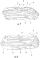
- FIG. 1-8 a tool, such as a multipurpose tool 10, according to one embodiment of the present invention is depicted. While the tool will be described in the context of a multipurpose tool, other types of tools may readily employ embodiments of the present invention including knives and other tools that are not considered multipurpose tools. For purposes of illustration, but not of limitation, a multipurpose tool employing an embodiment of the present invention will now be described.
- the multipurpose tool 10 includes a plurality of handles 12 configured for movement relative to one another, as well a plurality of tool members carried by at least one of the handles.
- the multipurpose tool includes a pair of generally elongate handles that extend between opposed ends.
- the handles can be moved toward and away from one another, such as in order to actuate a tool member as described below.
- the multipurpose tool 10 may be configured such that the handles 12 are adapted for relative movement between an open position as shown in Figures 1-4 and a closed position as shown in Figures 5-8 and discussed hereinafter.
- the multipurpose tool has a compact form factor in the closed position so as to facilitate transport and storage of the multipurpose tool. While the multipurpose tool is more expansive in the open position, one or more of the tool members of the multipurpose tool are accessible and capable of being utilized in the open position, even though those same tool member(s) are stowed and generally inaccessible in the closed position.
- Each handle 12 includes a pair of opposed sidewalls 12a and a floor 12b having a web interconnecting the opposed sidewalls such that a cavity is defined within the handle to receive and store a plurality of tool members.
- a multipurpose tool 10 of one embodiment may include first and second handles 12 that are connected to the opposed jaws 14 of a tool member 16 having pivotable jaws, such as the pliers of the illustrated embodiment. In the open configuration, the handles may be moved toward one another in order to close the jaws of the pliers and away from one another in order to open the jaws of the pliers.
- the jaws of the pliers are configured to contact one another once the jaws are in a fully opened position in order to prevent further opening of the jaws. Even though the jaws cannot be opened any further, the handles can be pivoted relative to the respective jaws in order to transition from the open position as shown in Figures 1-4 to the closed position as shown in Figures 5-8 .
- each handle 12 may transition from the closed position shown in Figures 5-8 to the open position shown in Figures 1-4 by pulling the handles away from one another and rotating the handles about the opposed jaws 14.
- the tool 10 may be configured to provide tactile feedback to a user indicating that the tool has been unfolded from a closed position to a fully open position.
- the jaws of this embodiment may include or otherwise be connected to and move in concert with a cam member 18.
- each handle may include a spring 20, such as a cantilever spring, disposed within the handle, such as by extending internally along the floor 12b of the handle.
- Figure 9 depicts the spring in each of three positions as the handle is rotated relative to the jaw from first and second transitional positions moving from a closed position to an open position to a third open position with the spring being shown in solid lines and the handle being shown in one of the positions in dashed lines.
- the spring has a distal end 22 that is biased into operable contact with the cam member.
- the cam member 18 may be eccentric. Indeed, the first portion 18a of the cam member that the distal end 22 of the spring 20 contacts and rides upon during the transition from a closed position to an open position may have a semicircular shape with a constant radius. Once the handles 12 are fully opened, however, the distal end of the spring moves into contact with a second portion 18b of the cam member that has a different size and/or shape.
- the second portion of the cam member with which the distal end of the spring is in contact once the handles are fully opened may have a smaller radius and/or may have a different shape and/or size, such as by being linear or otherwise defining a smaller profile, than the remainder of the cam member.
- the eccentric cam member 18 may also create a differential in the force, such as an increase in the force, required to fold the handles 12 as the distal end 22 of the spring 20 transitions from the second portion 18b of the cam member to the larger semicircular first portion 18a of the cam member.
- a differential in the force such as an increase in the force, required to fold the handles 12 as the distal end 22 of the spring 20 transitions from the second portion 18b of the cam member to the larger semicircular first portion 18a of the cam member.
- the increase in force required to fold the handles may decrease the likelihood that a user may inadvertently fold or close up the handles.
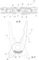
- the jaws 14 may be biased, such as to an open position.
- a spring 30, such as a coil spring, may extend between base portions of the jaws, thereby biasing the jaws to be open in the absence of additional forces, as shown, for example, in Figures 10 and 11 .
- the jaws may be configured to define a pocket extending therebetween and externally accessible without having to disassemble the tool 10. As such, if the spring breaks or otherwise suffers degradation in its performance the spring may be removed, such as by compressing the spring with tweezers, a screwdriver, a knife blade or the like. Another spring, that is, a replacement spring, may than be installed.
- each jaw 14 may define a protrusion upon which a respective end of the spring may be seated.
- the spring may be maintained in position between the handles 12 until a user affirmatively removes the spring.
- the multipurpose tool 10 can include a variety of tool members.
- the multipurpose tool can include a tool member 16 having pivotable jaws 14, such as the pliers described above.
- the tool member having pivotable jaws can also include wire cutters and/or wire strippers, or scissors, if desired.
- the multipurpose tool of the embodiment depicted in Figures 1-8 includes a knife blade 32 and a saw 34 carried by the handles 12.
- the knife blade and the saw may be rotatably connected to the respective handles.
- the mulitipurpose tool may also include guards 36 operably connected to the handles with each guard defining a pocket with respect to a sidewall 12a of the respective handle within which the knife blade or saw may be stowed.
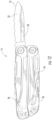
- the knife blade (as well as the saw) can be unfolded to a deployed position as shown in Figure 12 , particularly in instances in which the multipurpose tool is in the closed configuration.
- the knife blade can define an opening 50, typically opposite the cutting edge 52, that a user can grasp in order to rotate the knife blade outwardly away from the handle 12.
- the guard 36 that is attached or otherwise integral to the frame of the respective handle covers the cutting edge of the knife blade while the knife blade is in a folded position.
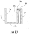
- the guard may be configured to have an L-shape in cross-section with an upstanding portion 54 of the guard extending alongside the folded knife blade 32 in a generally parallel orientation relative to the sidewalls 12a of the handle 12.
- the guard of this embodiment may also include a laterally extending portion 56 that extends generally perpendicular to the sidewalls of the handle.
- the distal edge 56a of the laterally extending portion may overlap the sidewall and, in one embodiment, may extend laterally inward from the upstanding portion to at least the inner edge of the sidewall, that is, the edge of the sidewall proximate the channel as shown, for example, in Figure 13 , which illustrates the guard and the handle in isolation.
- the distal edge of the laterally extending portion of the blade guard may be aligned with the inner edge of the sidewall of the handle.
- the multipurpose tool 10 can also include additional tool members 38, such as a screwdriver, bit driver, bottle opener, can opener, saw, razor, gut hook or the like, that are folded into the channel defined by a handle 12.
- additional tool members 38 such as a screwdriver, bit driver, bottle opener, can opener, saw, razor, gut hook or the like, that are folded into the channel defined by a handle 12.
- these tool members may include a nail nick to facilitate a user's interaction with and engagement of a tool member, the nail nicks may become worn or otherwise filled with residue over time such that the usefulness of the nail nick is reduced.
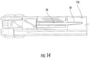
- the handle may define an opening 40 through which tool members are visible.
- the floor 12b of the handle may include a web that extends between the opposed sidewalls 12a.
- the web may, in turn, define an opening through which tool members foldable within the respective handle are accessible, as shown in Figures 3, 4 , 7 and 8 . While the opening defined by the web may be differently sized and shaped, the opening may have the same general shape and the same or a slightly larger size than the tool members foldable into the handle. In this regard, the tool members may be disposed alongside one another in a stowed position within the handle so as to define a composite tool profile. As shown in Figure 14 , for example, the web of the floor of the handle may define an opening having a shape that corresponds to the composite tool profile.
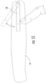
- a user may insert a finger into the opening 40 and push or otherwise force a selected tool member outwardly from the handle 12, as shown in Figure 15 . While a user may not be able to fully unfold the tool member by force applied through the opening defined by the web of the floor 12b, the tool member may be advanced beyond the handle by a sufficient amount that a user may then grasp or otherwise engage the tool member so as to fully unfold the tool member.
- each tool member may include an icon or other designation 42 that identifies the respective tool member.
- the tool member may include the icon or other designation at various different positions, but the tool members of one embodiment include the icon or other designations along the spline of the respective tool member.
- the icon or other designation may be applied in various manners, the icon or other designation may be molded, etched or otherwise formed into the tool member, such as along the spline of the tool.
- the icons or other designations 42 carried by tool members may be staggered in a lengthwise direction as defined by the longitudinally extending axis of the handle.
- tool members that lie next to other tool members may define a notch 44 aligned axially, that is, along the longitudinal axis of the handle, with the position of the icon or other designation of the adjacent tool member, as shown in Figure 16 .
- icons or other designations of tool members may be visible through the notch(es) even when the tool is one of a plurality of tools that lie side-by-side.
- the handle may also define a window 46 aligned with an icons or other designations to permit the icons or other designations to be readily viewed. By considering the icon or designation, a user may have increased confidence that the correct tool member will be selected.
Landscapes
- Engineering & Computer Science (AREA)
- Mechanical Engineering (AREA)
- Scissors And Nippers (AREA)
- Knives (AREA)
Claims (18)
- Mehrzweckwerkzeug (10), Folgendes umfassend:
eine Vielzahl von Griffen (12), die für eine relative Bewegung zwischen einer geschlossenen Position und einer offenen Position konfiguriert ist, wobei die Vielzahl von Griffen einen ersten Griff umfasst, der eine Längsachse zwischen gegenüberliegenden Enden des ersten Griffs definiert und Folgendes umfasst:gegenüberliegende Seitenwände (12a) und einen Boden (12b), der sich zwischen den gegenüberliegenden Seitenwänden erstreckt;eine Vielzahl von Werkzeugelementen (38), die von mindestens einem ersten Griff getragen werden und in den ersten Griff klappbar sind, so dass die Werkzeugelemente für eine Bewegung durch eine erste offene Seite des ersten Griffs, die dem Boden gegenüberliegt, zwischen einer verstauten Position und einer offenen Position konfiguriert sind, wobei die Vielzahl von Werkzeugelementen in einer verstauten Position nebeneinander angeordnet sind, um ein zusammengesetztes Werkzeugprofil zu definieren,dadurch gekennzeichnet, dass der Boden des ersten Griffs einen Steg aufweist, der sich zwischen den gegenüberliegenden Seitenwänden erstreckt und eine Öffnung (40) mit einer Form definiert, die dem zusammengesetzten Werkzeugprofil entspricht, wobei die durch den Steg definierte Öffnung die gleiche allgemeine Form und die gleiche Größe wie die Vielzahl von Werkzeugelementen aufweist, die in den ersten Griff klappbar sind, und wobei die Vielzahl von Werkzeugelementen durch die Öffnung zugänglich ist. - Mehrzweckwerkzeug (10) nach Anspruch 1, ferner umfassend:eine erste und eine zweite Klemmbacke (14), die drehbar mit dem ersten bzw. zweiten Griff (12) verbunden sind; undeine Feder (30), die zwischen der ersten und der zweiten Klemmbacke angeordnet und so konfiguriert ist, dass sie die Klemmbacken in eine offene Position spannen,wobei die Feder so angeordnet ist, dass sie in einem Fall sichtbar und zugänglich ist, wenn sich der erste und der zweite Griff in der offenen Position befinden.
- Mehrzweckwerkzeug (10) nach einem der Ansprüche 1 oder 2, ferner umfassend:eine erste und eine zweite Klemmbacke (14), die drehbar mit dem ersten bzw. zweiten Griff (12) verbunden sind, wobei die erste und die zweite Backe jeweils exzentrische Nockenelemente (18) aufweisen; undeine erste und zweite Feder (20), die von den ersten bzw. zweiten Griffen getragen werden und auf den exzentrischen Nockenelementen der ersten bzw. zweiten Klemmbacken aufliegen.
- Mehrzweckwerkzeug nach Anspruch 3, wobei die exzentrischen Nockenelemente (18) der ersten und der zweiten Klemmbacke (12) jeweils einen ersten Abschnitt (18a) aufweisen, auf dem die erste und die zweite Feder (20) aufliegen, wenn der erste und der zweite Griff von der geschlossenen Stellung in die geöffnete Stellung übergehen, und einen zweiten Abschnitt (18b), der mindestens eine andere Form oder eine andere Größe als der erste Abschnitt aufweist, wobei die erste und die zweite Feder auf dem zweiten Abschnitt aufliegen, wenn der erste und der zweite Griff die geöffnete Stellung erreichen.
- Mehrzweckwerkzeug (10) nach einem der Ansprüche 1 bis 4, wobei jedes Werkzeugelement (38) eine Bezeichnung (42) aufweist, die für das jeweilige Werkzeugelement repräsentativ ist, und wobei die Bezeichnungen der Werkzeugelemente entlang einer sich in Längsrichtung erstreckenden Achse des ersten Griffs (12) unterschiedlich angeordnet sind.
- Mehrzweckwerkzeug (10), umfassend:eine Vielzahl von Griffen (12), die für eine relative Bewegung zwischen einer geschlossenen Position und einer offenen Position konfiguriert sind, wobei die Vielzahl von Griffen einen ersten Griff umfasst, der eine sich in Längsrichtung erstreckende Achse definiert; undeine Vielzahl von Werkzeugelementen (38), die von mindestens einem ersten Griff getragen werden und in den ersten Griff klappbar sind, dadurch gekennzeichnet, dassjedes Werkzeugelement eine Bezeichnung (42) aufweist, die für das jeweilige Werkzeugelement repräsentativ ist, wobei die Bezeichnung in das Werkzeugelement eingegossen, geätzt oder geformt ist, wobei die Bezeichnungen der Werkzeugelemente entlang der sich in Längsrichtung erstreckenden Achse unterschiedlich angeordnet sind.
- Mehrzweckwerkzeug (10) nach Anspruch 6, wobei mindestens eines der Werkzeugelemente (12) eine Kerbe (44) definiert, die entlang der Längsachse mit der Bezeichnung eines benachbarten Werkzeugteils (38) ausgerichtet ist, so dass die Bezeichnung (42) des benachbarten Werkzeugelements (38) durch die Kerbe (44) sichtbar ist.
- Mehrzweckwerkzeug (10) nach Anspruch 6 oder Anspruch 7, wobei der erste Griff (12) ein Paar gegenüberliegender Seitenwände (12a) umfasst, die einen Kanal definieren, in den die Vielzahl der Werkzeugelemente (38) klappbar sind, und wobei eine Seitenwand des ersten Griffs ein Fenster (46) definiert, das entlang der sich in Längsrichtung erstreckenden Achse mit der Bezeichnung von mindestens einem der Werkzeugelemente ausgerichtet ist.
- Mehrzweckwerkzeug nach einem der Ansprüche 6 bis 8, wobei die Vielzahl der Griffe (12) ferner einen zweiten Griff umfasst, und wobei das Mehrzweckwerkzeug ferner umfasst:eine erste und eine zweite Klemmbacke (14), die drehbar mit dem ersten bzw. dem zweiten Griff verbunden sind; undeine Feder (30), die zwischen der ersten und der zweiten Klemmbacke positioniert und so konfiguriert ist, dass sie die Klemmbacken in eine offene Position vorspannt,wobei die Feder so positioniert ist, dass sie in einem Fall sichtbar und zugänglich ist, in dem sich der erste und der zweite Griff in der offenen Position befinden.
- Mehrzweckwerkzeug (10) nach einem der Ansprüche 6 bis 9, wobei die Vielzahl der Griffe (12) ferner einen zweiten Griff umfasst, und wobei das Mehrzweckwerkzeug ferner umfasst:eine erste und eine zweite Klemmbacke (14), die drehbar mit dem ersten bzw. dem zweiten Griff verbunden sind, wobei die erste und die zweite Klemmbacke jeweils exzentrische Nockenelemente (18) umfassen; undeine erste und zweite Feder (20), die von dem ersten bzw. zweiten Griff getragen werden und auf den exzentrischen Nockenelementen der ersten bzw. zweiten Klemmbacken aufliegen.
- Mehrzweckwerkzeug (10) nach Anspruch 10, wobei die exzentrischen Nockenelemente (18) der ersten und der zweiten Klemmbacke (14) jeweils einen ersten Abschnitt (18a) aufweisen, auf dem die erste und die zweite Feder (20) aufliegen, wenn der erste und der zweite Griff (12) von der geschlossenen Stellung in die geöffnete Stellung übergehen, und einen zweiten Abschnitt (18b), der mindestens eine andere Form oder eine andere Größe als der erste Abschnitt aufweist, wobei die erste und zweite Feder auf dem zweiten Abschnitt aufliegen, wenn der erste und der zweite Griff die offene Stellung erreichen.
- Mehrzweckwerkzeug (10) nach einem der Ansprüche 6 bis 11, wobei die Vielzahl der Werkzeugelemente (38) in einer verstauten Position nebeneinander angeordnet sind, um ein zusammengesetztes Werkzeugprofil zu definieren, wobei der erste Griff (12) gegenüberliegende Seitenwände (12a) und einen Boden (12b) aufweist, der sich zwischen den gegenüberliegenden Seitenwänden erstreckt, und wobei der Boden des ersten Griffs einen Steg aufweist, der sich zwischen den gegenüberliegenden Seitenwänden erstreckt, und eine Öffnung (40) mit einer Form definiert, die dem zusammengesetzten Werkzeugprofil entspricht.
- Werkzeug (10), umfassend:einen ersten Griff (12) mit einer ersten und einer zweiten Seitenwand (12a) und einem dazwischen definierten Kanal;ein Werkzeugelement (34, 34), das an einer Außenfläche der ersten Seitenwand des ersten Griffs befestigt ist und relativ dazu zwischen einer geschlossenen und einer offenen Position klappbar ist;eine Schutzvorrichtung (36), die funktionsfähig mit dem ersten Griff verbunden ist, wobei die Schutzvorrichtung einen aufrechten Abschnitt (54) und einen sich seitlich erstreckenden Abschnitt (56) umfasst, wobei das Werkzeugelement zwischen der ersten Seitenwand des ersten Griffs und der Schutzvorrichtung in einem Fall angeordnet ist, in dem sich das Werkzeugelement in der geschlossenen Position befindet, dadurch gekennzeichnet, dasssich eine distale Kante (56a) des sich seitlich erstreckenden Abschnitts der Schutzvorrichtung mindestens bis zu einer Innenfläche der ersten Seitenwand des ersten Griffs in der Nähe des Kanals erstreckt und mit dieser ausgerichtet ist.
- Werkzeug (10) nach Anspruch 13, wobei die Schutzvorrichtung (36) einschließlich des aufrechten Teils (54) und des sich seitlich erstreckenden Teils (56) im Querschnitt eine L-Form aufweist.
- Werkzeug (10) nach Anspruch 13 oder Anspruch 14, wobei das Werkzeug ein Mehrzweckwerkzeug umfasst, ferner Folgendes umfassend:einen zweiten Griff (12), der für eine Relativbewegung mit dem ersten Griff zwischen einer geschlossenen Position und einer offenen Position konfiguriert ist;eine erste und eine zweite Klemmbacke (14), die drehbar mit dem ersten bzw. zweiten Griff verbunden sind; undeine Feder (30), die zwischen der ersten und der zweiten Klemmbacke positioniert und konfiguriert ist, um die Klemmbacken in eine offene Position vorzuspannen.
- Werkzeug (10) nach Anspruch 15, wobei die Feder (30) so angeordnet ist, dass sie in einem Fall, in dem sich der erste und der zweite Griff (12) in der offenen Position befinden, sichtbar und zugänglich ist.
- Werkzeug (10) nach einem der Ansprüche 13 bis 16, wobei das Werkzeug ein Mehrzweckwerkzeug umfasst, ferner umfassend:einen zweiten Griff (12), der für eine Relativbewegung mit dem ersten Griff zwischen einer geschlossenen Position und einer offenen Position konfiguriert ist;eine erste und eine zweite Klemmbacke (14), die drehbar mit dem ersten bzw. zweiten Griff verbunden sind, wobei die erste und die zweite Klemmbacke jeweilige exzentrische Nockenelemente (18) umfassen; undeine erste und eine zweite Feder (20), die von dem ersten bzw. zweiten Griff getragen werden und auf den exzentrischen Nockenelementen der ersten bzw. zweiten Klammbacke aufliegen.
- Werkzeug (10) nach Anspruch 17, wobei die exzentrischen Nockenelemente (18) der ersten und der zweiten Klemmbacke (14) jeweils einen ersten Abschnitt (18a) aufweisen, auf dem die erste und die zweite Feder (20) aufliegen, wenn der erste und der zweite Griff (12) von der geschlossenen Stellung in die geöffnete Stellung übergehen, und einen zweiten Abschnitt (18b), der mindestens eine andere Form oder eine andere Größe als der erste Abschnitt aufweist, wobei die erste und die zweite Feder auf dem zweiten Abschnitt aufliegen, wenn der erste und der zweite Griff die offene Position erreichen.
Applications Claiming Priority (1)
| Application Number | Priority Date | Filing Date | Title |
|---|---|---|---|
| US12/972,251 US9095970B2 (en) | 2010-12-17 | 2010-12-17 | Multipurpose tool configured to facilitate access to individual tool members |
Publications (4)
| Publication Number | Publication Date |
|---|---|
| EP2465645A2 EP2465645A2 (de) | 2012-06-20 |
| EP2465645A3 EP2465645A3 (de) | 2017-07-19 |
| EP2465645C0 EP2465645C0 (de) | 2024-08-28 |
| EP2465645B1 true EP2465645B1 (de) | 2024-08-28 |
Family
ID=45350696
Family Applications (1)
| Application Number | Title | Priority Date | Filing Date |
|---|---|---|---|
| EP11193883.3A Active EP2465645B1 (de) | 2010-12-17 | 2011-12-15 | Mehrzweck-Werkzeug, das zum leichten Zugang auf individuelle Werkzeugelemente konfiguriert ist |
Country Status (4)
| Country | Link |
|---|---|
| US (2) | US9095970B2 (de) |
| EP (1) | EP2465645B1 (de) |
| AU (1) | AU2011253766B2 (de) |
| ZA (1) | ZA201109272B (de) |
Families Citing this family (16)
| Publication number | Priority date | Publication date | Assignee | Title |
|---|---|---|---|---|
| US9701004B2 (en) | 2011-10-25 | 2017-07-11 | Fiskars Brands, Inc. | Multi-purpose tool having removable handle for use as a hand tool |
| US8857299B2 (en) * | 2012-01-14 | 2014-10-14 | Leatherman Tool Group, Inc. | Hand tool |
| USD716128S1 (en) * | 2012-12-28 | 2014-10-28 | Fiskars Brands, Inc. | Multi-tool |
| CN203210339U (zh) * | 2013-03-07 | 2013-09-25 | 林洁清 | 一种剪和工具钳组合工具 |
| CN103552007B (zh) * | 2013-11-13 | 2015-12-09 | 上海齐迈五金有限公司 | 一种双头钳子 |
| USD719432S1 (en) * | 2013-11-15 | 2014-12-16 | Lincoln Global, Inc. | Welding multi-tool |
| US9440346B2 (en) | 2014-01-06 | 2016-09-13 | Leatherman Tool Group, Inc. | Tool having a tool member configured for subsequent installation |
| US9751201B2 (en) * | 2014-11-13 | 2017-09-05 | The Patent Store Llc | Landscape lighting pocket tool |
| US11292105B2 (en) | 2016-06-01 | 2022-04-05 | Leatherman Tool Group, Inc. | Multipurpose tool having accessible tool members |
| USD850882S1 (en) * | 2017-07-20 | 2019-06-11 | Noobo Manufacture Co., Ltd. | Multi-function tool |
| US10857653B2 (en) | 2017-08-24 | 2020-12-08 | Scott B. Merrill | Systems and methods for selectively securing a cylindrical body |
| US10926396B2 (en) | 2018-06-19 | 2021-02-23 | Leatherman Tool Group, Inc. | Tool having one or more rotatable tool members |
| USD994457S1 (en) * | 2021-03-15 | 2023-08-08 | Miaoli Feng | Multifunctional tool |
| USD1007266S1 (en) * | 2021-03-28 | 2023-12-12 | Yingxiang Fu | Multi-functional plier |
| USD1007989S1 (en) * | 2021-05-12 | 2023-12-19 | Yangdong Haoxiang Industry And Trade Co., Ltd. | Multifunctional plier |
| USD1041286S1 (en) * | 2024-05-12 | 2024-09-10 | Xiaofeng FU | Multifunctional folding plier |
Family Cites Families (19)
| Publication number | Priority date | Publication date | Assignee | Title |
|---|---|---|---|---|
| JPS62501749A (ja) * | 1985-01-01 | 1987-07-16 | ウェンゲル・ソシエテ・アノニム | モジュ−ル式ポケットナイフ |
| US5745997A (en) * | 1995-11-29 | 1998-05-05 | Leatherman Tool Group, Inc. | Multi-purpose tool including folding scissors |
| US5765247A (en) * | 1996-01-11 | 1998-06-16 | Buck Knives, Inc. | Hand tool with multiple locking blades controlled by a single locking mechanism and release |
| US5697114A (en) | 1996-02-29 | 1997-12-16 | Bear Mgc Cutlery Co., Inc. | Folding multi-tool |
| US6098225A (en) | 1996-02-29 | 2000-08-08 | Bear Mgc Cutlery Co., Inc. | Folding hand shears |
| US6006385A (en) * | 1996-10-31 | 1999-12-28 | Kai U.S.A. Ltd. | Multi-tool |
| US6625832B2 (en) * | 1996-12-20 | 2003-09-30 | Alterra Holdings Corporation | Multi-function tool with cartridge |
| US6014787A (en) | 1997-10-30 | 2000-01-18 | Leatherman Tool Group, Inc. | Multipurpose folding tool with easily accessible outer blades |
| US6226822B1 (en) | 1999-10-25 | 2001-05-08 | Jin-Fu Chen | Tool structure |
| US6694558B2 (en) * | 2000-06-15 | 2004-02-24 | Great Neck Saw Manufacturers, Inc. | Foldable hand tool |
| US6389626B1 (en) * | 2000-10-24 | 2002-05-21 | Kun Chih Hung | Tool structure |
| US6622328B2 (en) * | 2000-10-31 | 2003-09-23 | Leatherman Tool Group, Inc. | Folding multipurpose pocket tool with floating springs |
| TW554807U (en) * | 2000-12-18 | 2003-09-21 | Shu-Te Wu | Compound tool set |
| US6564678B1 (en) * | 2002-01-29 | 2003-05-20 | Lo-Pin Wang | Combination of tool kits |
| US7353736B2 (en) * | 2005-07-27 | 2008-04-08 | Leatherman Tool Group, Inc. | Enhanced multi-function hand tool |
| US7946201B2 (en) * | 2007-03-28 | 2011-05-24 | Sog Specialty Knives & Tools, Llc | Discrete multitool locking method and apparatus |
| US7712399B2 (en) * | 2007-10-05 | 2010-05-11 | Leatherman Tool Group, Inc. | Tool and associated bit driver |
| WO2011121396A1 (en) * | 2010-04-01 | 2011-10-06 | Crank Brothers, Inc. | Multiple tool |
| US8857299B2 (en) * | 2012-01-14 | 2014-10-14 | Leatherman Tool Group, Inc. | Hand tool |
-
2010
- 2010-12-17 US US12/972,251 patent/US9095970B2/en active Active
-
2011
- 2011-12-01 AU AU2011253766A patent/AU2011253766B2/en active Active
- 2011-12-15 ZA ZA2011/09272A patent/ZA201109272B/en unknown
- 2011-12-15 EP EP11193883.3A patent/EP2465645B1/de active Active
-
2015
- 2015-08-03 US US14/816,695 patent/US10086506B2/en active Active
Also Published As
| Publication number | Publication date |
|---|---|
| EP2465645C0 (de) | 2024-08-28 |
| US10086506B2 (en) | 2018-10-02 |
| AU2011253766A1 (en) | 2012-07-05 |
| EP2465645A3 (de) | 2017-07-19 |
| US20150336258A1 (en) | 2015-11-26 |
| EP2465645A2 (de) | 2012-06-20 |
| US9095970B2 (en) | 2015-08-04 |
| AU2011253766B2 (en) | 2015-04-23 |
| US20120151681A1 (en) | 2012-06-21 |
| ZA201109272B (en) | 2012-08-29 |
Similar Documents
| Publication | Publication Date | Title |
|---|---|---|
| EP2465645B1 (de) | Mehrzweck-Werkzeug, das zum leichten Zugang auf individuelle Werkzeugelemente konfiguriert ist | |
| AU2021202402B2 (en) | Multipurpose tool having accessible tool members | |
| AU2012247033B2 (en) | Hand Tool | |
| EP2324962B1 (de) | Werkzeug mit integriertem Karabiner | |
| CN107427996A (zh) | 多功能工具 | |
| EP3623110B1 (de) | Werkzeug mit einem oder mehreren drehbaren werkzeugelementen | |
| EP2898995B1 (de) | Werkzeug mit einem Werkzeugelement zum nachträglichen Einbau | |
| EP3544771B1 (de) | Isoliertes multiwerkzeug | |
| AU2018203316B2 (en) | Multipurpose tool | |
| HK40024428A (en) | Multipurpose tool having accessible tool members | |
| HK40024428B (en) | Multipurpose tool having accessible tool members | |
| HK1250502B (en) | Multipurpose tool having accessible tool members | |
| HK1240890B (en) | Multipurpose tool | |
| HK1240890A1 (en) | Multipurpose tool |
Legal Events
| Date | Code | Title | Description |
|---|---|---|---|
| PUAI | Public reference made under article 153(3) epc to a published international application that has entered the european phase |
Free format text: ORIGINAL CODE: 0009012 |
|
| AK | Designated contracting states |
Kind code of ref document: A2 Designated state(s): AL AT BE BG CH CY CZ DE DK EE ES FI FR GB GR HR HU IE IS IT LI LT LU LV MC MK MT NL NO PL PT RO RS SE SI SK SM TR |
|
| AX | Request for extension of the european patent |
Extension state: BA ME |
|
| PUAL | Search report despatched |
Free format text: ORIGINAL CODE: 0009013 |
|
| AK | Designated contracting states |
Kind code of ref document: A3 Designated state(s): AL AT BE BG CH CY CZ DE DK EE ES FI FR GB GR HR HU IE IS IT LI LT LU LV MC MK MT NL NO PL PT RO RS SE SI SK SM TR |
|
| AX | Request for extension of the european patent |
Extension state: BA ME |
|
| RIC1 | Information provided on ipc code assigned before grant |
Ipc: B25F 1/00 20060101AFI20170613BHEP Ipc: B25F 1/04 20060101ALI20170613BHEP |
|
| STAA | Information on the status of an ep patent application or granted ep patent |
Free format text: STATUS: REQUEST FOR EXAMINATION WAS MADE |
|
| 17P | Request for examination filed |
Effective date: 20180119 |
|
| RBV | Designated contracting states (corrected) |
Designated state(s): AL AT BE BG CH CY CZ DE DK EE ES FI FR GB GR HR HU IE IS IT LI LT LU LV MC MK MT NL NO PL PT RO RS SE SI SK SM TR |
|
| STAA | Information on the status of an ep patent application or granted ep patent |
Free format text: STATUS: EXAMINATION IS IN PROGRESS |
|
| 17Q | First examination report despatched |
Effective date: 20190912 |
|
| GRAP | Despatch of communication of intention to grant a patent |
Free format text: ORIGINAL CODE: EPIDOSNIGR1 |
|
| STAA | Information on the status of an ep patent application or granted ep patent |
Free format text: STATUS: GRANT OF PATENT IS INTENDED |
|
| INTG | Intention to grant announced |
Effective date: 20240319 |
|
| GRAS | Grant fee paid |
Free format text: ORIGINAL CODE: EPIDOSNIGR3 |
|
| GRAA | (expected) grant |
Free format text: ORIGINAL CODE: 0009210 |
|
| STAA | Information on the status of an ep patent application or granted ep patent |
Free format text: STATUS: THE PATENT HAS BEEN GRANTED |
|
| AK | Designated contracting states |
Kind code of ref document: B1 Designated state(s): AL AT BE BG CH CY CZ DE DK EE ES FI FR GB GR HR HU IE IS IT LI LT LU LV MC MK MT NL NO PL PT RO RS SE SI SK SM TR |
|
| REG | Reference to a national code |
Ref country code: GB Ref legal event code: FG4D |
|
| REG | Reference to a national code |
Ref country code: CH Ref legal event code: EP |
|
| REG | Reference to a national code |
Ref country code: DE Ref legal event code: R096 Ref document number: 602011074949 Country of ref document: DE |
|
| REG | Reference to a national code |
Ref country code: IE Ref legal event code: FG4D |
|
| U01 | Request for unitary effect filed |
Effective date: 20240927 |
|
| U07 | Unitary effect registered |
Designated state(s): AT BE BG DE DK EE FI FR IT LT LU LV MT NL PT RO SE SI Effective date: 20241016 |
|
| PG25 | Lapsed in a contracting state [announced via postgrant information from national office to epo] |
Ref country code: NO Free format text: LAPSE BECAUSE OF FAILURE TO SUBMIT A TRANSLATION OF THE DESCRIPTION OR TO PAY THE FEE WITHIN THE PRESCRIBED TIME-LIMIT Effective date: 20241128 |
|
| PG25 | Lapsed in a contracting state [announced via postgrant information from national office to epo] |
Ref country code: GR Free format text: LAPSE BECAUSE OF FAILURE TO SUBMIT A TRANSLATION OF THE DESCRIPTION OR TO PAY THE FEE WITHIN THE PRESCRIBED TIME-LIMIT Effective date: 20241129 Ref country code: PL Free format text: LAPSE BECAUSE OF FAILURE TO SUBMIT A TRANSLATION OF THE DESCRIPTION OR TO PAY THE FEE WITHIN THE PRESCRIBED TIME-LIMIT Effective date: 20240828 |
|
| U20 | Renewal fee for the european patent with unitary effect paid |
Year of fee payment: 14 Effective date: 20241216 |
|
| PG25 | Lapsed in a contracting state [announced via postgrant information from national office to epo] |
Ref country code: IS Free format text: LAPSE BECAUSE OF FAILURE TO SUBMIT A TRANSLATION OF THE DESCRIPTION OR TO PAY THE FEE WITHIN THE PRESCRIBED TIME-LIMIT Effective date: 20241228 |
|
| PG25 | Lapsed in a contracting state [announced via postgrant information from national office to epo] |
Ref country code: HR Free format text: LAPSE BECAUSE OF FAILURE TO SUBMIT A TRANSLATION OF THE DESCRIPTION OR TO PAY THE FEE WITHIN THE PRESCRIBED TIME-LIMIT Effective date: 20240828 |
|
| PG25 | Lapsed in a contracting state [announced via postgrant information from national office to epo] |
Ref country code: ES Free format text: LAPSE BECAUSE OF FAILURE TO SUBMIT A TRANSLATION OF THE DESCRIPTION OR TO PAY THE FEE WITHIN THE PRESCRIBED TIME-LIMIT Effective date: 20240828 Ref country code: RS Free format text: LAPSE BECAUSE OF FAILURE TO SUBMIT A TRANSLATION OF THE DESCRIPTION OR TO PAY THE FEE WITHIN THE PRESCRIBED TIME-LIMIT Effective date: 20241128 |
|
| PG25 | Lapsed in a contracting state [announced via postgrant information from national office to epo] |
Ref country code: RS Free format text: LAPSE BECAUSE OF FAILURE TO SUBMIT A TRANSLATION OF THE DESCRIPTION OR TO PAY THE FEE WITHIN THE PRESCRIBED TIME-LIMIT Effective date: 20241128 Ref country code: PL Free format text: LAPSE BECAUSE OF FAILURE TO SUBMIT A TRANSLATION OF THE DESCRIPTION OR TO PAY THE FEE WITHIN THE PRESCRIBED TIME-LIMIT Effective date: 20240828 Ref country code: NO Free format text: LAPSE BECAUSE OF FAILURE TO SUBMIT A TRANSLATION OF THE DESCRIPTION OR TO PAY THE FEE WITHIN THE PRESCRIBED TIME-LIMIT Effective date: 20241128 Ref country code: IS Free format text: LAPSE BECAUSE OF FAILURE TO SUBMIT A TRANSLATION OF THE DESCRIPTION OR TO PAY THE FEE WITHIN THE PRESCRIBED TIME-LIMIT Effective date: 20241228 Ref country code: HR Free format text: LAPSE BECAUSE OF FAILURE TO SUBMIT A TRANSLATION OF THE DESCRIPTION OR TO PAY THE FEE WITHIN THE PRESCRIBED TIME-LIMIT Effective date: 20240828 Ref country code: GR Free format text: LAPSE BECAUSE OF FAILURE TO SUBMIT A TRANSLATION OF THE DESCRIPTION OR TO PAY THE FEE WITHIN THE PRESCRIBED TIME-LIMIT Effective date: 20241129 Ref country code: ES Free format text: LAPSE BECAUSE OF FAILURE TO SUBMIT A TRANSLATION OF THE DESCRIPTION OR TO PAY THE FEE WITHIN THE PRESCRIBED TIME-LIMIT Effective date: 20240828 |
|
| PG25 | Lapsed in a contracting state [announced via postgrant information from national office to epo] |
Ref country code: SM Free format text: LAPSE BECAUSE OF FAILURE TO SUBMIT A TRANSLATION OF THE DESCRIPTION OR TO PAY THE FEE WITHIN THE PRESCRIBED TIME-LIMIT Effective date: 20240828 |
|
| PG25 | Lapsed in a contracting state [announced via postgrant information from national office to epo] |
Ref country code: CZ Free format text: LAPSE BECAUSE OF FAILURE TO SUBMIT A TRANSLATION OF THE DESCRIPTION OR TO PAY THE FEE WITHIN THE PRESCRIBED TIME-LIMIT Effective date: 20240828 |
|
| PG25 | Lapsed in a contracting state [announced via postgrant information from national office to epo] |
Ref country code: SK Free format text: LAPSE BECAUSE OF FAILURE TO SUBMIT A TRANSLATION OF THE DESCRIPTION OR TO PAY THE FEE WITHIN THE PRESCRIBED TIME-LIMIT Effective date: 20240828 |
|
| PLBE | No opposition filed within time limit |
Free format text: ORIGINAL CODE: 0009261 |
|
| STAA | Information on the status of an ep patent application or granted ep patent |
Free format text: STATUS: NO OPPOSITION FILED WITHIN TIME LIMIT |
|
| PG25 | Lapsed in a contracting state [announced via postgrant information from national office to epo] |
Ref country code: MC Free format text: LAPSE BECAUSE OF FAILURE TO SUBMIT A TRANSLATION OF THE DESCRIPTION OR TO PAY THE FEE WITHIN THE PRESCRIBED TIME-LIMIT Effective date: 20240828 |
|
| REG | Reference to a national code |
Ref country code: CH Ref legal event code: PL |
|
| 26N | No opposition filed |
Effective date: 20250530 |
|
| PG25 | Lapsed in a contracting state [announced via postgrant information from national office to epo] |
Ref country code: CH Free format text: LAPSE BECAUSE OF NON-PAYMENT OF DUE FEES Effective date: 20241231 |
|
| PG25 | Lapsed in a contracting state [announced via postgrant information from national office to epo] |
Ref country code: IE Free format text: LAPSE BECAUSE OF NON-PAYMENT OF DUE FEES Effective date: 20241215 |
|
| PGFP | Annual fee paid to national office [announced via postgrant information from national office to epo] |
Ref country code: GB Payment date: 20251229 Year of fee payment: 15 |
|
| U20 | Renewal fee for the european patent with unitary effect paid |
Year of fee payment: 15 Effective date: 20251229 |