EP2465601B1 - Electrodialytic separation of gas - Google Patents
Electrodialytic separation of gas Download PDFInfo
- Publication number
- EP2465601B1 EP2465601B1 EP11193856.9A EP11193856A EP2465601B1 EP 2465601 B1 EP2465601 B1 EP 2465601B1 EP 11193856 A EP11193856 A EP 11193856A EP 2465601 B1 EP2465601 B1 EP 2465601B1
- Authority
- EP
- European Patent Office
- Prior art keywords
- solution
- pressure
- electrodialysis
- gas
- stack
- Prior art date
- Legal status (The legal status is an assumption and is not a legal conclusion. Google has not performed a legal analysis and makes no representation as to the accuracy of the status listed.)
- Active
Links
- 238000000926 separation method Methods 0.000 title description 13
- 239000000243 solution Substances 0.000 claims description 287
- 238000000909 electrodialysis Methods 0.000 claims description 200
- 239000007789 gas Substances 0.000 claims description 142
- 239000012528 membrane Substances 0.000 claims description 61
- BWHMMNNQKKPAPP-UHFFFAOYSA-L potassium carbonate Chemical compound [K+].[K+].[O-]C([O-])=O BWHMMNNQKKPAPP-UHFFFAOYSA-L 0.000 claims description 51
- 238000000034 method Methods 0.000 claims description 40
- 230000008569 process Effects 0.000 claims description 36
- 239000011736 potassium bicarbonate Substances 0.000 claims description 33
- 229910000028 potassium bicarbonate Inorganic materials 0.000 claims description 33
- TYJJADVDDVDEDZ-UHFFFAOYSA-M potassium hydrogencarbonate Chemical compound [K+].OC([O-])=O TYJJADVDDVDEDZ-UHFFFAOYSA-M 0.000 claims description 33
- 229910000027 potassium carbonate Inorganic materials 0.000 claims description 25
- BVKZGUZCCUSVTD-UHFFFAOYSA-M Bicarbonate Chemical compound OC([O-])=O BVKZGUZCCUSVTD-UHFFFAOYSA-M 0.000 claims description 21
- 239000003929 acidic solution Substances 0.000 claims description 13
- 239000003637 basic solution Substances 0.000 claims description 11
- BVKZGUZCCUSVTD-UHFFFAOYSA-L Carbonate Chemical compound [O-]C([O-])=O BVKZGUZCCUSVTD-UHFFFAOYSA-L 0.000 claims description 10
- UIIMBOGNXHQVGW-UHFFFAOYSA-M Sodium bicarbonate Chemical compound [Na+].OC([O-])=O UIIMBOGNXHQVGW-UHFFFAOYSA-M 0.000 claims description 10
- NBIIXXVUZAFLBC-UHFFFAOYSA-N Phosphoric acid Chemical compound OP(O)(O)=O NBIIXXVUZAFLBC-UHFFFAOYSA-N 0.000 claims description 9
- CDBYLPFSWZWCQE-UHFFFAOYSA-L Sodium Carbonate Chemical compound [Na+].[Na+].[O-]C([O-])=O CDBYLPFSWZWCQE-UHFFFAOYSA-L 0.000 claims description 8
- XLYOFNOQVPJJNP-UHFFFAOYSA-M hydroxide Chemical compound [OH-] XLYOFNOQVPJJNP-UHFFFAOYSA-M 0.000 claims description 7
- 230000003014 reinforcing effect Effects 0.000 claims description 7
- 239000012266 salt solution Substances 0.000 claims description 6
- 150000001768 cations Chemical class 0.000 claims description 5
- 229910000030 sodium bicarbonate Inorganic materials 0.000 claims description 5
- 229910000029 sodium carbonate Inorganic materials 0.000 claims description 4
- HZAXFHJVJLSVMW-UHFFFAOYSA-N 2-Aminoethan-1-ol Chemical compound NCCO HZAXFHJVJLSVMW-UHFFFAOYSA-N 0.000 claims description 3
- 230000001172 regenerating effect Effects 0.000 claims description 3
- NBIIXXVUZAFLBC-UHFFFAOYSA-L Phosphate ion(2-) Chemical compound OP([O-])([O-])=O NBIIXXVUZAFLBC-UHFFFAOYSA-L 0.000 claims 1
- 229910000147 aluminium phosphate Inorganic materials 0.000 claims 1
- NBIIXXVUZAFLBC-UHFFFAOYSA-M dihydrogenphosphate Chemical compound OP(O)([O-])=O NBIIXXVUZAFLBC-UHFFFAOYSA-M 0.000 claims 1
- CURLTUGMZLYLDI-UHFFFAOYSA-N Carbon dioxide Chemical compound O=C=O CURLTUGMZLYLDI-UHFFFAOYSA-N 0.000 description 152
- 239000001569 carbon dioxide Substances 0.000 description 150
- 229910002092 carbon dioxide Inorganic materials 0.000 description 150
- KWYUFKZDYYNOTN-UHFFFAOYSA-M Potassium hydroxide Chemical compound [OH-].[K+] KWYUFKZDYYNOTN-UHFFFAOYSA-M 0.000 description 61
- 239000002253 acid Substances 0.000 description 47
- 239000002585 base Substances 0.000 description 40
- 239000003014 ion exchange membrane Substances 0.000 description 31
- 239000007788 liquid Substances 0.000 description 21
- 230000009467 reduction Effects 0.000 description 16
- 238000002474 experimental method Methods 0.000 description 12
- 230000007423 decrease Effects 0.000 description 11
- XLYOFNOQVPJJNP-UHFFFAOYSA-N water Substances O XLYOFNOQVPJJNP-UHFFFAOYSA-N 0.000 description 10
- HEMHJVSKTPXQMS-UHFFFAOYSA-M Sodium hydroxide Chemical compound [OH-].[Na+] HEMHJVSKTPXQMS-UHFFFAOYSA-M 0.000 description 9
- 150000002500 ions Chemical class 0.000 description 9
- 238000011069 regeneration method Methods 0.000 description 9
- 230000032258 transport Effects 0.000 description 9
- 238000005265 energy consumption Methods 0.000 description 8
- 239000000446 fuel Substances 0.000 description 8
- 230000008859 change Effects 0.000 description 7
- 239000012530 fluid Substances 0.000 description 7
- 230000008929 regeneration Effects 0.000 description 6
- 239000007836 KH2PO4 Substances 0.000 description 5
- -1 SO2 or NH3 Chemical compound 0.000 description 5
- 230000002378 acidificating effect Effects 0.000 description 5
- 239000003011 anion exchange membrane Substances 0.000 description 5
- 230000037427 ion transport Effects 0.000 description 5
- 229910000402 monopotassium phosphate Inorganic materials 0.000 description 5
- GNSKLFRGEWLPPA-UHFFFAOYSA-M potassium dihydrogen phosphate Chemical compound [K+].OP(O)([O-])=O GNSKLFRGEWLPPA-UHFFFAOYSA-M 0.000 description 5
- 239000000126 substance Substances 0.000 description 5
- QGZKDVFQNNGYKY-UHFFFAOYSA-N Ammonia Chemical compound N QGZKDVFQNNGYKY-UHFFFAOYSA-N 0.000 description 4
- 150000001450 anions Chemical class 0.000 description 4
- 239000007864 aqueous solution Substances 0.000 description 4
- 230000006399 behavior Effects 0.000 description 4
- 238000005341 cation exchange Methods 0.000 description 4
- 238000006243 chemical reaction Methods 0.000 description 4
- 229910001414 potassium ion Inorganic materials 0.000 description 4
- 230000010349 pulsation Effects 0.000 description 4
- 230000001629 suppression Effects 0.000 description 4
- QGZKDVFQNNGYKY-UHFFFAOYSA-O Ammonium Chemical compound [NH4+] QGZKDVFQNNGYKY-UHFFFAOYSA-O 0.000 description 3
- OKKJLVBELUTLKV-UHFFFAOYSA-N Methanol Chemical compound OC OKKJLVBELUTLKV-UHFFFAOYSA-N 0.000 description 3
- LSNNMFCWUKXFEE-UHFFFAOYSA-N Sulfurous acid Chemical compound OS(O)=O LSNNMFCWUKXFEE-UHFFFAOYSA-N 0.000 description 3
- 238000005349 anion exchange Methods 0.000 description 3
- 238000010494 dissociation reaction Methods 0.000 description 3
- 230000005593 dissociations Effects 0.000 description 3
- 230000000694 effects Effects 0.000 description 3
- 238000005516 engineering process Methods 0.000 description 3
- 238000011010 flushing procedure Methods 0.000 description 3
- 229930195733 hydrocarbon Natural products 0.000 description 3
- 150000002430 hydrocarbons Chemical class 0.000 description 3
- QAOWNCQODCNURD-UHFFFAOYSA-M hydrogensulfate Chemical compound OS([O-])(=O)=O QAOWNCQODCNURD-UHFFFAOYSA-M 0.000 description 3
- 238000001802 infusion Methods 0.000 description 3
- 238000005259 measurement Methods 0.000 description 3
- 239000000203 mixture Substances 0.000 description 3
- 230000009919 sequestration Effects 0.000 description 3
- 239000004215 Carbon black (E152) Substances 0.000 description 2
- UGFAIRIUMAVXCW-UHFFFAOYSA-N Carbon monoxide Chemical compound [O+]#[C-] UGFAIRIUMAVXCW-UHFFFAOYSA-N 0.000 description 2
- 230000002730 additional effect Effects 0.000 description 2
- BVKZGUZCCUSVTD-UHFFFAOYSA-N carbonic acid Chemical compound OC(O)=O BVKZGUZCCUSVTD-UHFFFAOYSA-N 0.000 description 2
- 239000004568 cement Substances 0.000 description 2
- 238000013461 design Methods 0.000 description 2
- 238000006073 displacement reaction Methods 0.000 description 2
- 239000003792 electrolyte Substances 0.000 description 2
- 239000003546 flue gas Substances 0.000 description 2
- 238000004519 manufacturing process Methods 0.000 description 2
- 239000000463 material Substances 0.000 description 2
- 238000002156 mixing Methods 0.000 description 2
- 238000010587 phase diagram Methods 0.000 description 2
- 235000015497 potassium bicarbonate Nutrition 0.000 description 2
- 238000010926 purge Methods 0.000 description 2
- 235000017557 sodium bicarbonate Nutrition 0.000 description 2
- 239000002904 solvent Substances 0.000 description 2
- 238000012546 transfer Methods 0.000 description 2
- OKTJSMMVPCPJKN-UHFFFAOYSA-N Carbon Chemical compound [C] OKTJSMMVPCPJKN-UHFFFAOYSA-N 0.000 description 1
- UFHFLCQGNIYNRP-UHFFFAOYSA-N Hydrogen Chemical compound [H][H] UFHFLCQGNIYNRP-UHFFFAOYSA-N 0.000 description 1
- YZCKVEUIGOORGS-UHFFFAOYSA-N Hydrogen atom Chemical compound [H] YZCKVEUIGOORGS-UHFFFAOYSA-N 0.000 description 1
- 150000007513 acids Chemical class 0.000 description 1
- 238000013459 approach Methods 0.000 description 1
- QVGXLLKOCUKJST-UHFFFAOYSA-N atomic oxygen Chemical compound [O] QVGXLLKOCUKJST-UHFFFAOYSA-N 0.000 description 1
- 230000008901 benefit Effects 0.000 description 1
- 230000015572 biosynthetic process Effects 0.000 description 1
- 229910052799 carbon Inorganic materials 0.000 description 1
- 239000003054 catalyst Substances 0.000 description 1
- 238000004891 communication Methods 0.000 description 1
- 239000000470 constituent Substances 0.000 description 1
- 238000013480 data collection Methods 0.000 description 1
- 230000003247 decreasing effect Effects 0.000 description 1
- 230000002939 deleterious effect Effects 0.000 description 1
- 230000001066 destructive effect Effects 0.000 description 1
- 230000005684 electric field Effects 0.000 description 1
- 238000010438 heat treatment Methods 0.000 description 1
- 239000001257 hydrogen Substances 0.000 description 1
- 229910052739 hydrogen Inorganic materials 0.000 description 1
- 238000010348 incorporation Methods 0.000 description 1
- 238000005342 ion exchange Methods 0.000 description 1
- 230000013011 mating Effects 0.000 description 1
- 238000012986 modification Methods 0.000 description 1
- 230000004048 modification Effects 0.000 description 1
- 230000007935 neutral effect Effects 0.000 description 1
- 230000010355 oscillation Effects 0.000 description 1
- 239000001301 oxygen Substances 0.000 description 1
- 229910052760 oxygen Inorganic materials 0.000 description 1
- 239000004033 plastic Substances 0.000 description 1
- 229920003023 plastic Polymers 0.000 description 1
- 238000011084 recovery Methods 0.000 description 1
- 230000000630 rising effect Effects 0.000 description 1
- 150000003839 salts Chemical class 0.000 description 1
- 238000005201 scrubbing Methods 0.000 description 1
- 125000006850 spacer group Chemical group 0.000 description 1
- 229910001220 stainless steel Inorganic materials 0.000 description 1
- 239000010935 stainless steel Substances 0.000 description 1
- 238000003786 synthesis reaction Methods 0.000 description 1
- 238000013022 venting Methods 0.000 description 1
Images


Classifications
-
- B—PERFORMING OPERATIONS; TRANSPORTING
- B01—PHYSICAL OR CHEMICAL PROCESSES OR APPARATUS IN GENERAL
- B01D—SEPARATION
- B01D61/00—Processes of separation using semi-permeable membranes, e.g. dialysis, osmosis or ultrafiltration; Apparatus, accessories or auxiliary operations specially adapted therefor
- B01D61/42—Electrodialysis; Electro-osmosis ; Electro-ultrafiltration; Membrane capacitive deionization
- B01D61/422—Electrodialysis
-
- B—PERFORMING OPERATIONS; TRANSPORTING
- B01—PHYSICAL OR CHEMICAL PROCESSES OR APPARATUS IN GENERAL
- B01D—SEPARATION
- B01D61/00—Processes of separation using semi-permeable membranes, e.g. dialysis, osmosis or ultrafiltration; Apparatus, accessories or auxiliary operations specially adapted therefor
- B01D61/42—Electrodialysis; Electro-osmosis ; Electro-ultrafiltration; Membrane capacitive deionization
- B01D61/44—Ion-selective electrodialysis
- B01D61/445—Ion-selective electrodialysis with bipolar membranes; Water splitting
-
- C—CHEMISTRY; METALLURGY
- C01—INORGANIC CHEMISTRY
- C01B—NON-METALLIC ELEMENTS; COMPOUNDS THEREOF; METALLOIDS OR COMPOUNDS THEREOF NOT COVERED BY SUBCLASS C01C
- C01B17/00—Sulfur; Compounds thereof
- C01B17/48—Sulfur dioxide; Sulfurous acid
- C01B17/50—Preparation of sulfur dioxide
- C01B17/501—Preparation of sulfur dioxide by reduction of sulfur compounds
-
- C—CHEMISTRY; METALLURGY
- C01—INORGANIC CHEMISTRY
- C01B—NON-METALLIC ELEMENTS; COMPOUNDS THEREOF; METALLOIDS OR COMPOUNDS THEREOF NOT COVERED BY SUBCLASS C01C
- C01B32/00—Carbon; Compounds thereof
- C01B32/05—Preparation or purification of carbon not covered by groups C01B32/15, C01B32/20, C01B32/25, C01B32/30
-
- C—CHEMISTRY; METALLURGY
- C01—INORGANIC CHEMISTRY
- C01C—AMMONIA; CYANOGEN; COMPOUNDS THEREOF
- C01C1/00—Ammonia; Compounds thereof
- C01C1/02—Preparation, purification or separation of ammonia
-
- B—PERFORMING OPERATIONS; TRANSPORTING
- B01—PHYSICAL OR CHEMICAL PROCESSES OR APPARATUS IN GENERAL
- B01D—SEPARATION
- B01D2257/00—Components to be removed
- B01D2257/50—Carbon oxides
- B01D2257/504—Carbon dioxide
-
- B—PERFORMING OPERATIONS; TRANSPORTING
- B01—PHYSICAL OR CHEMICAL PROCESSES OR APPARATUS IN GENERAL
- B01D—SEPARATION
- B01D2313/00—Details relating to membrane modules or apparatus
- B01D2313/24—Specific pressurizing or depressurizing means
-
- B—PERFORMING OPERATIONS; TRANSPORTING
- B01—PHYSICAL OR CHEMICAL PROCESSES OR APPARATUS IN GENERAL
- B01D—SEPARATION
- B01D53/00—Separation of gases or vapours; Recovering vapours of volatile solvents from gases; Chemical or biological purification of waste gases, e.g. engine exhaust gases, smoke, fumes, flue gases, aerosols
- B01D53/14—Separation of gases or vapours; Recovering vapours of volatile solvents from gases; Chemical or biological purification of waste gases, e.g. engine exhaust gases, smoke, fumes, flue gases, aerosols by absorption
- B01D53/1425—Regeneration of liquid absorbents
-
- B—PERFORMING OPERATIONS; TRANSPORTING
- B01—PHYSICAL OR CHEMICAL PROCESSES OR APPARATUS IN GENERAL
- B01D—SEPARATION
- B01D53/00—Separation of gases or vapours; Recovering vapours of volatile solvents from gases; Chemical or biological purification of waste gases, e.g. engine exhaust gases, smoke, fumes, flue gases, aerosols
- B01D53/14—Separation of gases or vapours; Recovering vapours of volatile solvents from gases; Chemical or biological purification of waste gases, e.g. engine exhaust gases, smoke, fumes, flue gases, aerosols by absorption
- B01D53/1456—Removing acid components
- B01D53/1475—Removing carbon dioxide
-
- Y—GENERAL TAGGING OF NEW TECHNOLOGICAL DEVELOPMENTS; GENERAL TAGGING OF CROSS-SECTIONAL TECHNOLOGIES SPANNING OVER SEVERAL SECTIONS OF THE IPC; TECHNICAL SUBJECTS COVERED BY FORMER USPC CROSS-REFERENCE ART COLLECTIONS [XRACs] AND DIGESTS
- Y02—TECHNOLOGIES OR APPLICATIONS FOR MITIGATION OR ADAPTATION AGAINST CLIMATE CHANGE
- Y02P—CLIMATE CHANGE MITIGATION TECHNOLOGIES IN THE PRODUCTION OR PROCESSING OF GOODS
- Y02P20/00—Technologies relating to chemical industry
- Y02P20/151—Reduction of greenhouse gas [GHG] emissions, e.g. CO2
-
- Y—GENERAL TAGGING OF NEW TECHNOLOGICAL DEVELOPMENTS; GENERAL TAGGING OF CROSS-SECTIONAL TECHNOLOGIES SPANNING OVER SEVERAL SECTIONS OF THE IPC; TECHNICAL SUBJECTS COVERED BY FORMER USPC CROSS-REFERENCE ART COLLECTIONS [XRACs] AND DIGESTS
- Y02—TECHNOLOGIES OR APPLICATIONS FOR MITIGATION OR ADAPTATION AGAINST CLIMATE CHANGE
- Y02P—CLIMATE CHANGE MITIGATION TECHNOLOGIES IN THE PRODUCTION OR PROCESSING OF GOODS
- Y02P20/00—Technologies relating to chemical industry
- Y02P20/50—Improvements relating to the production of bulk chemicals
- Y02P20/54—Improvements relating to the production of bulk chemicals using solvents, e.g. supercritical solvents or ionic liquids
Definitions
- the concentration of atmospheric carbon dioxide (CO 2 ) continues to rise, as shown by, for example, IPCC, Climate Change 2007: Synthesis Report. Contribution of Working Groups I, II and III to the Fourth Assessment Report of the Intergovernmental Panel on Climate Change, 2007 [Core Writing Team, Pachauri, R.K and Reisinger, A. (eds.)], IPCC, Geneva, Switzerland, 104 pp . It is becoming increasingly imperative to invent efficient and cost-effective technologies for controlling the atmospheric CO 2 concentration.
- the concentration of atmospheric carbon dioxide (CO 2 ) is rising at the rate of approximately 2 parts per million per year (ppm/yr). The challenge of reducing the concentration of atmospheric CO 2 represents an opportunity to invent new, cost-effective technologies to solve this problem.
- Techniques for removing CO 2 from streams of mixed gases typically involve a two-step process of capture and regeneration.
- a stream of pure CO 2 gas is regenerated from this CO 2 -rich aqueous post-capture solution.
- pre-capture solutions exist, with different solutions being preferred depending on the concentration of CO 2 in the mixed gas source.
- aqueous hydroxide pre-capture solutions such as potassium hydroxide (KOH) or sodium hydroxide (NaOH), aqueous carbonate pre-capture solutions such as potassium carbonate (K 2 CO 3 ) or sodium carbonate (Na 2 CO 3 ), or aqueous bicarbonate pre-capture solutions such as potassium bicarbonate (KHCO 3 ) or sodium bicarbonate (NaHCO 3 ) are likely candidates for CO 2 pre-capture solutions.
- KOH potassium hydroxide
- NaOH sodium hydroxide
- aqueous carbonate pre-capture solutions such as potassium carbonate (K 2 CO 3 ) or sodium carbonate (Na 2 CO 3 )
- aqueous bicarbonate pre-capture solutions such as potassium bicarbonate (KHCO 3 ) or sodium bicarbonate (NaHCO 3 ) are likely candidates for CO 2 pre-capture solutions.
- pre-capture solutions are known, for example, monoethanolamine (MEA), which is used in gas stream scrubbing applications to remove, for example, CO 2 from flue gas.
- MEA monoethanolamine
- the capture of CO 2 gas into these pre-capture solutions converts the original hydroxide/carbonate/bicarbonate pre-capture solutions into a more acidic post-capture solution consisting of a mixture of hydroxide (KOH or NaOH), carbonate (K 2 CO 3 or Na 2 CO 3 ), and/or potassium bicarbonate (KHCO 3 ) or sodium bicarbonate (NaHCO 3 ) post-capture solutions, as examples.
- KOH or NaOH hydroxide
- carbonate K 2 CO 3 or Na 2 CO 3
- KHCO 3 potassium bicarbonate
- NaHCO 3 sodium bicarbonate
- the CO 2 gas is captured from the mixed-gas stream into the pre-capture solutions in the ionic forms CO 3 (2-) and/or HCO 3 - to form the post-capture solutions, pure CO 2 gas is typically regenerated from the solution.
- the overall effect of this process of capture and regeneration is the separation and concentration of CO 2 gas from a pre-separation mixed-gas stream with a relatively low mole fraction of CO 2 gas into a post-separation gas stream that possesses a higher mole fraction of CO 2 gas than the pre-separation stream.
- the mole fraction of CO 2 in the post-separation stream may be unity, that is, the post-separation stream may be a pure stream of CO 2 gas.
- the post-separation gas can then be, for example, geologically sequestered, or incorporated into useful products such as concrete, as shown by Calera, Green Cement for a Blue Planet, http://www.calera.com/index.php/technology/technology_vision/ (last visited Sept. 9, 2010 ); plastics, as shown by G.A. Olah et al., Beyond Oil and Gas: The Methanol Economy, Wiley-VCH (2006 ); or liquid hydrocarbon fuels, as shown by F.S. Zeman & D.W. Keith, Carbon Neutral Hydrocarbons, Phil. Trans. R. Soc.
- Bipolar membrane electrodialysis can be used to convert aqueous salt solution into acids and bases without the addition of other chemicals.
- a component of BPMED devices is ion exchange membranes used to separate ionic species in solution when an electrical field is applied across the membranes. Performing BPMED on certain solutions may create gas bubbles adjacent to the membrane surface that can block ion transport and reduce the effective membrane surface area, causing increased cell resistance and localized "hot spots" of very high current density that lead to shortened membrane lifetimes.
- commonly used input and output solutions are selected so that they do not evolve significant quantities of gas inside the membrane stack at ambient pressure, which excludes an entire class of gas-evolving solutions from electrodialytic treatment.
- Example embodiments address these and other disadvantages of the conventional art.
- EP2163294A1 discloses a system and method for recovery of CO 2 by utilizing a process for producing gas with an electrodialysis apparatus.
- bipolar membrane electrodialysis (BPMED) apparatuses include an electrodialysis stack made up of at least one electrodialysis cell.
- the electrodialysis cell includes at least one bipolar membrane (BPM) such that, when an electrical potential is applied across the cell, the dissociation of water into hydrogen (H + ) and hydroxide (OH - ) ions occurs.
- BPM bipolar membrane
- a BPM is formed from a cation-exchange layer laminated together with an anion-exchange layer, as well as a junction layer between the cation and anion layers. Water diffuses into the junction layer, reaching the usual equilibrium with H + and OH - ions according to its dissociation constant.
- a BPM is oriented such that the anion-exchange layer faces the anode (positive electrode) end of the BPMED apparatus and the cation-exchange layer faces the cathode (negative electrode) end of the apparatus. This orientation allows the OH - ions to be transported across the anion-exchange layer and the H + anions to be transported across the cation-exchange layer when an electrical potential is applied across the membrane stack.
- the constituent cations and anions of an input salt solution are separated under the applied electrical potential via ion exchange membranes-either anion exchange membranes (AEMs), cation exchange membranes (CEMs), or some combination of the two.
- AEMs anion exchange membranes
- CEMs cation exchange membranes
- the OH - (H + ) ions "produced" by the BPM then combine with the cations (anions) separated from the input salt solution to produce basic (acidic) output solutions containing the parent acid and base of the input salt.
- a diluted salt solution may also be produced as output in addition to the acid and base output solutions.
- a BPMED membrane stack can have either a two-compartment or a three-compartment configuration.
- adjacent membranes may alternate between BPM and AEM to form a membrane stack of the form BPM, AEM, BPM, AEM, etc.; or adjacent membranes may alternate between BPM and CEM to form a membrane stack of the form BPM, CEM, BPM, CEM, etc.
- adjacent membranes may cycle from BPM to AEM to CEM, forming a membrane stack of the form BPM, AEM, CEM, BPM, AEM, CEM, etc.
- Electrodialysis without bipolar membranes is also possible, and consists of a two-compartment configuration formed by an alternating series of AEM and CEM to form a membrane stack of the form AEM, CEM, AEM, CEM, AEM, etc.
- gas bubbles inside commercially available BPMED systems result in gas bubbles adjacent to the membrane surface that can block ion transport in this region and reduce the effective membrane surface area, resulting in increased resistance and localized "hot spots" of very high current density that lead to shortened membrane lifetimes.
- commonly used input and output solutions are selected so that they do not evolve significant quantities of gas inside the membrane stack at ambient pressure. This excludes an entire class of gas-evolving solutions from electrodialytic treatment.
- these challenges are overcome by operating an electrodialysis apparatus at high pressure, i.e., above ambient pressure.
- the operating pressure is sufficiently high, given other process conditions, that a gas that would typically evolve out of solution into the membrane stack at ambient pressure instead remains dissolved in solution, preventing gas bubble evolution inside the membrane stack itself.
- the pressure of the solution containing the dissolved gas can be reduced downstream of the membrane stack so that the dissolved gas evolves out of solution and can be collected for other uses, if desired.
- the pressure to which the solution is reduced can be any pressure less than the operating pressure of the membrane stack. In this way, the gas can be evolved at pressures greater than ambient pressure, and can also be evolved at pressures less than ambient pressure, if desired.
- Electrodialysis apparatuses may allow, for example, for energy-efficient, high-rate concentration of CO 2 in a compact, reliable unit from the aqueous carbonate/bicarbonate capture solutions to pure or nearly pure CO 2 gas suitable, for example, to sequester, to incorporate into useful products, or to react with other inputs to synthesize liquid hydrocarbon fuels.
- gas, liquid, supercritical fluid, or some combination thereof is generated using embodiments of the process described herein depends on 1) the temperature and pressure at which the electrodialysis is performed, and 2) the input solution composition.
- either CO 2 gas, CO 2 liquid, or supercritical CO 2 may be generated, depending on the temperature and pressure used.
- CO 2 gas, CO 2 liquid, or supercritical CO 2 may be generated, depending on the temperature and pressure used.
- the operating pressure and temperature fall on the gas portion of the CO 2 phase diagram, for example at a pressure of approximately 10 atm and a temperature of approximately 20°C
- CO 2 is generated in the output solution as a gas.
- the operating pressure and temperature used fall within the liquid portion of the CO 2 phase diagram, for example approximately 100 atm and 20°C, CO 2 liquid is generated.
- a gas is absorbed into aqueous solution at some pressure p low
- High-pressure electrodialysis is then performed on the solution, and then the same gas is regenerated at a pressure p high with p high > p low .
- the embodiments may be used as novel gas pressurization devices capable of replacing inefficient mechanical compressors.
- pressurization is accomplished more efficiently than with standard processes.
- this allows direct generation of CO 2 at the pressures required for certain uses of the regenerated CO 2 , such as sequestration and reaction to a liquid fuel, for example. This may also be a benefit for other gases that could be directly regenerated at the elevated pressure required for a subsequent reaction step.
- SO 2 gas can be produced when aqueous sulfite or bisulfate solutions are input into the system and made more acidic via operation of the system
- NH 3 gas can be produced when aqueous ammonium solutions are input into the system and made more basic via operation of the system.
- Processes to generate gas using high-pressure electrodialysis disclosed here reduce the energy consumption of electrodialysis of gas-evolving solutions, especially at the high current densities typically desired for real-world application.
- Embodiment processes also reduce the voltage across the electrodialysis membrane stack for electrodialysis of gas-evolving solutions, especially at the high current densities typically desired for real-world application.
- Electrodialytic generation of CO 2 has the potential to be less destructive to and more compatible with the homogenous catalysts for CO 2 capture than thermal/chemical regeneration methods. It also has the potential to be less capital intensive and space-consuming than thermal/chemical regeneration methods, and to be more easily scaled down for mobile applications, such as military fuel generation, than thermal/chemical regeneration methods.
- FIG. 1 is a schematic of an embodiment of a high-pressure electrodialysis system.
- the system includes an apparatus for conducting two-compartment electrodialysis consisting of three different loops: one for a first solution loop, one for a second solution loop, and one for an electrode solution loop.
- the system includes an apparatus for conducting three-compartment elctrodialysis includes consisting of four different loops: one for a first solution, one for a second solution, one for a third solution, and one for an electrode solution loop.
- FIG. 1 depicts a system with three loops such that an apparatus for conducting two-compartment BPMED or electrodialysis without bipolar membranes can be incorporated in the system, it will be appreciated that the system can be adapted to instead incorporate a three-compartment BPMED apparatus by incorporating an additional loop for a third solution.
- the first solution is a basic solution and the second solution is an acidic solution.
- the first solution is an acidic solution and the second solution is a basic solution.
- An electrode solution may be, for example, an electrolyte.
- the third solution may be, for example, a salt solution that is diluted upon passing through the operating electrodialysis unit.
- Each loop can be operated in either bypass or stack mode. When a loop operates in bypass mode, the solutions bypass the electrodialysis membrane stack of the high-pressure electrodialysis apparatus 110.
- Each loop includes one or more tanks (for example, first solution tank 100), a pump (for example, first solution pump 104), a pulsation dampener (for example, first solution pulsation dampener 107), one or more temperature and pH meters (for example, meter 116), one or more temperature and conductivity meters (for example, meter 117), one or more pressure and flow meters (for example, meters 123 and 123), valves to change the operation mode between bypass mode and stack mode (for example, valves 112 and 120), and a valve to adjust the pressure of the electrodialysis apparatus 110 (for example, valve 121).
- tanks for example, first solution tank 100
- a pump for example, first solution pump 104
- a pulsation dampener for example, first solution pulsation dampener 107
- temperature and pH meters
- the high-pressure electrodialysis system also includes a high-pressure electrodialysis apparatus 110.
- FIG. 2 shows an exploded view of a high-pressure electrodialysis apparatus for use in a high-pressure electrodialysis system according to an embodiment.
- the high-pressure electrodialysis apparatus includes an anode (held at a positive electrical potential relative to the cathode) end 201 and a cathode (held at a negative electrical potential relative to the anode) end 202.
- the apparatus includes a housing that includes axial support members 203 and reinforcing members 204. When the apparatus is assembled, the axial support members 203 are mated together to form a cell chamber in which an electrodialysis membrane stack 205 is received.
- the reinforcing members 204 are configured to apply a compressive force in the axial direction when they are coupled together, for example, by a bolted connection, such that the axial support members 203 are mated and the electrodialysis apparatus can operate at pressures above ambient pressure, ambient pressure being defined as the pressure naturally occurring in the environment surrounding the apparatus. At an elevation of sea-level, the ambient pressure is typically around 1 atm, or 101.325 kPa.
- the high-pressure electrodialysis apparatus can operate at pressures up to and including 20 atm. In an embodiment, the high-pressure electrodialysis apparatus can operate at pressures above 20 atm.
- the axial support member 203 at the anode end 201 includes at least one pressurization port 216.
- the pressurization port 216 allows the pressure between the interior of the electrodialysis membrane stack 205 and the cell chamber formed by the mating of axial support members 203 to equalize by diverting a portion of the electrode solution into the region of the cell chamber outside the electrodialysis stack 205.
- the electrodialysis stack 205 includes one or more electrodialysis cells 206.
- the electrodialysis stack 205 may include one or more cells 206 configured to carry out electrodialysis without bipolar membranes, or one or more cells configured to carry out BPMED.
- Cells configured to carry out BPMED may be either two-compartment or three-compartment cells.
- the electrodialysis cell 206 in FIG. 2 includes two cell gaskets 207 arranged in alternating order with first and second ion exchange membranes 208 and 209.
- the cell 206 could carry out electrodialysis without bipolar membranes if, for example, first ion exchange membrane 208 was an AEM and second ion exchange membrane 209 was a CEM.
- first ion exchange membrane 208 was a BPM
- second ion exchange membrane 209 was an AEM or a CEM. It will be recognized that other configurations of membrane types may be possible, depending on input solutions used and the desired output solution.
- the electrodialysis stack 205 may also include end gaskets 211 at one or both ends of the stack, end ion exchange membranes 210 at one or both ends of the stack, and an additional cell gasket 212 interposed between the nth electrodialysis cell 206 and the end ion exchange membrane 210 at the cathode end 202 of the membrane stack 205. It will be recognized that whether end ion exchange membranes 210 and an additional cell gasket 212 are needed, and what types of ion exchange membranes 210 are appropriate, depends on the input solutions used and the desired output solution.
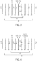
- FIG. 3 shows a schematic of electrodialysis membrane stack operation used to generate CO 2 gas in a high-pressure electrodialysis apparatus that contains one two-compartment BPMED cell.
- CO 2 generation is depicted, it will be understood that other gases may be generated using the illustrated stack configuration and process, depending on the inputs into the system.
- the electrodialysis cell 302 is composed of two cell gaskets 303 and 305, and two ion exchange membranes 304 and 306 arranged in alternating order in the axial direction with the cell gaskets 303 and 305.
- the electrodialysis stack 301 also includes two end ion exchange membranes 307 and 308; the electrodialysis cell 302 is interposed between the two end ion exchange membranes 307 and 308.
- the electrodialysis stack also includes an additional cell gasket 309 interposed between the second ion exchange membrane 306 of the electrodialysis cell 302 and the second end ion exchange membrane 308.
- the electrodialysis stack 301 also includes two end gaskets 310 and 311; the first end gasket 310 is interposed between the anode end electrode 312 of the apparatus and the first end ion exchange membrane 307, and the second end gasket 311 is interposed between the cathode end electrode 313 of the apparatus and the second end ion exchange membrane 308.
- the first ion exchange membrane 304 is a BPM
- the second ion exchange membrane 306 is an AEM
- the end ion exchange membranes 307 and 308 are CEMs.
- a basic solution (pH > 7) is generated between the first CEM 307 and the BPM 304
- an acidic solution (pH ⁇ 7) is generated between the BPM 304 and the AEM 306.
- gas may evolve out of the acidic solution between the BPM 304 and the AEM 306, or the gas may remain dissolved in the acidic solution.
- the input aqueous solutions are an electrode solution of KOH flowing between the anode 312 and the end CEM 307 in the solution compartment defined by gasket 310 and also flowing between the cathode 313 and the end CEM 308 in the solution compartment defined by gasket 311; a base solution of KHCO 3 and K 2 CO 3 flowing between the end CEM 307 and BPM 304 in the solution compartment defined by gasket 303 and also flowing between the AEM 306 and the end CEM 308 in the solution compartment defined by gasket 309; and an acid solution of KH 2 PO 4 and H 3 PO 4 flowing between the BPM 304 and the AEM 306 in the solution compartment defined by gasket 305.
- K + ions are transferred across end CEM 307 from the electrode solution in the compartment defined by gasket 310; OH - and H + ions are dissociated across the BPM 304; and HCO 3 - and CO 3 2- are transferred across AEM 306 from the basic solution in the compartment defined by gasket 309.
- the K + ions combine with the dissociated OH - ions to generate KOH between the first CEM 307 and the BPM 304; the H+ ions combine with HCO 3 - and CO 3 2- ions to form H 2 CO 3 and dissolved CO 2 in the solution compartment defined by gasket 305 between the BPM 304 and the AEM 306.
- the electrodialysis stack 205 includes more than one two-compartment cell. In an embodiment, the electrodialysis stack includes, for example, seven two-compartment cells.
- the electrodialysis apparatus can be adapted to receive any other number of cells.
- the cell is not configured to perform BPMED, but rather performs electrodialysis without bipolar membranes.
- the first ion exchange membrane 304 may be an AEM
- the second ion exchange membrane 306 may be a CEM.
- the electrodialysis stack includes one or more three-compartment cells instead.
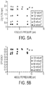
- FIG. 4 shows a schematic of electrodialysis stack operation to generate CO 2 gas in a high-pressure BPMED apparatus that contains one three-compartment cell. Although CO 2 generation is depicted, it will be understood that other gases may be generated using the illustrated stack configuration and process, depending on the inputs into the system.
- the electrodialysis cell 402 is composed of three cell gaskets 403, 405, 407, and three ion exchange membranes 404, 406, 408 arranged in alternating order in the axial direction with the cell gaskets 403, 405, 407.
- the electrodialysis stack 401 also includes two end gaskets 411 and 412; the first end gasket 411 is interposed between the anode end electrode 413 of the apparatus and the end ion exchange membrane 409, and the second end gasket 412 is interposed between the cathode end electrode 414 of the apparatus and the electrodialysis cell 402.
- the electrodialysis stack 401 also includes one end ion exchange membrane 409 interposed between the electrodialysis cell 402 and the end gasket 411.
- the first ion exchange membrane 404 is a BPM
- the second ion exchange membrane 406 is an AEM
- the third ion exchange membrane 408 is a CEM
- the end ion exchange membranes 409 is a CEM.
- a basic solution is generated between the end ion exchange membrane 409 and the BPM 404
- an acidic solution and CO 2 gas are generated between the BPM 404 and the AEM 406
- a desalted input solution is generated between the AEM 406 and the CEM 408.
- the input solutions may include an electrode solution of KOH in compartments defined by gaskets 411 and 412, a basic solution of KHCO 3 and K 2 CO 3 in compartments defined by gaskets 403 and 407, and an acidic solution of KH 2 PO 4 and H 3 PO 4 in the compartment defined by gasket 405.
- K + ions are transferred across end CEM 409 from the electrode solution in the compartment defined by end gasket 411 and across CEM 408 into the electrode solution in the compartment defined by end gasket 412; OH - and H + ions are dissociated across the BPM 404; and HCO 3 - and CO 3 2- are transferred across AEM 406 from the basic solution in the compartment defined by gasket 407.
- the K + ions combine with the dissociated OH - ions to generate KOH between the end ion exchange membrane 409 and the BPM 404; the H + ions combine with HCO 3 - and CO 3 2- ions to form H 2 CO 3 and dissolved CO 2 in the solution compartment defined by gasket 405 between the BPM 404 and the AEM 406; and a diluted KHCO 3 and K 2 CO 3 solution, less concentrated than the input solution, is generated between the AEM 406 and the CEM 408.
- the electrodialysis stack 401 includes more than one three-compartment cell 402. In an embodiment, the electrodialysis stack 401 includes, for example, seven three-compartment cells 402. The electrodialysis apparatus can be adapted to receive any other number of cells.
- the high-pressure electrodialysis apparatus also includes ports, which allow the solutions to flow into and out of the apparatus.
- the ports may be bossed ports formed in the axial support members 203 that slide through bossed port holes formed in the reinforcing members 204; flange adapters 213 may then be fitted over each bossed port and attached to the reinforcing members 204.
- each end 201 and 202 of the housing includes four ports total: one first solution port, one second solution port, and two electrode solution ports.
- the first and second solution ports may be inlet ports at the anode end 201, allowing solutions to flow into the apparatus; the corresponding first and second solution ports at the cathode end 202 would be outlet ports, allowing solutions to flow out of the apparatus.
- the flow of the apparatus can be reversed if desired such that the ports at the anode end 201 are outlet ports and those at the cathode end 202 are inlet ports.
- the flow can be such that there is an input port for one solution and an output port for the other solution at anode end 201, and an output port for the solution whose input port is at the anode end and an input port for the solution whose output port is at the anode end, at the cathode end 202.
- Each end of the apparatus has both an electrode solution inlet port and an electrode solution outlet port.
- each end 201 and 202 of the housing includes six ports total: one first solution port, one second solution port, one third solution port, and two electrode solution ports. The flows through these ports may be the same as those described above for a two-compartment or non-BPMED cell stack.
- the high-pressure electrodialysis apparatus also includes two electrodes 214, one at either end of the electrodialysis stack 205, and two electrode grates 215, each interposed between one of the electrodes 214 and the electrodialysis stack 205.
- the electrodialysis apparatus also includes two stress reduction cylinders 217, one attached to each reinforcing member 204.
- the electrodialysis apparatus shown in FIG. 2 is incorporated into the high-pressure electrodialysis system shown in FIG. 1 as the electrodialysis apparatus 110.
- the electrodialysis apparatus 110 includes a BPMED electrodialysis stack
- the electrodialysis system of FIG. 1 can be used, for example, to regenerate CO 2 gas from aqueous carbonate and bicarbonate solutions.
- gas may evolve out of solution inside the electrodialysis apparatus, or the gas may remain dissolved in the solution until the solution is no longer inside the electrodialysis apparatus.
- tanks 100-103 of the high-pressure electrodialysis system are designed to withstand pressures up to approximately 20 atm with a safety factor of about 3.
- the tanks 100-103 can be pressurized to any pressure between ambient pressure and the absolute pressure of the electrodialysis stack. When the tanks are so pressurized, gas evolves out of solution at a pressure above ambient pressure, i.e., at a pressure substantially the same as the pressure of the tanks 100-103.
- the covers of the tanks 100-103 have three threaded holes of a diameter of 1 ⁇ 4 inch for optional pipe connections and a fill cap of a diameter of 1 1/8 inch to fill the tanks 100-103.
- the first and second solution tanks 100 and 101 each have both an inlet coming from the bypass or the electrodialysis apparatus 110 and an outlet going to the first solution pump 104 or second solution pump 105 respectively. Both tanks 100 and 101 have a feed-through where the pH and the conductivity meters 116 and 117 are introduced into the solution.
- the cover of the second solution tank 101 is equipped with a vent and a 1/8 inch pipe for gas infusion.
- the first solution tank 100 has two windows to observe the evolution of gas bubbles from the solution.
- the tank cover may be equipped with a pressure sensor to know the pressure of the tank.
- the tank may also be equipped with two vents: one that leads the gas to a valve and a flow meter in order to regulate and measure the flow of gas evolving from the solution, and one to empty the headspace and flush the tank with gas.
- the first and second solution tanks 100 and 101 both have meters for measuring, showing, and recording certain information about the tank conditions.
- the first solution tank 100 may include a temperature and pH information and recording to computer (TXIR) meter 116 that measures, shows, and records the temperature and pH of the first solution.
- the first solution tank 100 may also include a TXIR meter 117 that measures, shows, and records the temperature and conductivity of the first solution.
- the second solution tank 101 may also have a TXIR meter 116 and TXIR meter 117 that perform the same functions for the second solution.
- the second solution tank 101 may also have a means for infusing gas into the second solution in order to regenerate the gas while operating through the electrodialysis stack.
- the second solution tank 101 may be a base solution tank that has a CO 2 gas bottle connected to it by, for example, a 1/8 inch pipe.
- the infusion of gas into the first solution tank 101 can be turned on or off using valve 118.
- the first solution loop also includes a valve 119 to drain the first solution loop and a valve 120 to change the operation from the bypass to the electrodialysis stack mode.
- the second solution loop also includes valves 119 and 120 that perform the same functions with respect to the second solution loop.
- the first solution loop also includes a valve 121 to change the pressure in the electrodialysis system and a valve 122 for taking samples.
- the second solution loop also includes valves 121 and 122 that perform the same functions with respect to the second solution loop.
- the pressure and the flow of the first solution loop are measured and recorded by pressure information and recording to computer (PIR) meter 123 and flow information and recording to computer (FIR) meter 124, respectively.
- the second solution loop also includes PIR meter 123 and FIR meter 124 that perform the same functions with respect to the second solution loop.
- the electrode solution loop has two tanks 102-103.
- Each tank 102-103 has an inlet coming from the bypass or the electrodialysis apparatus 110 and an outlet going to the electrode solution pump 106.
- the electrode solution tank 102 is for the electrode solution coming from the anode end 201 of the electrodialysis apparatus 110 (see FIG. 2 ) from where oxygen will evolve.
- the electrode solution tank 103 is for the fluid coming from the cathode end 202 of the electrodialysis apparatus 110 (see FIG. 2 ) from where hydrogen will evolve.
- each tank 102-103 is equipped with a pipe connection that has a 1 ⁇ 4 inch barb fitting to vent the tanks from the evolving gases. The vent of tank 103 may be connected to the building exhaust to avoid high H 2 concentrations in the atmosphere.
- the electrode solution loop also has a valve 111 to drain the electrode solution loop. It may also include two valves 112 to change the operation from the bypass to the electrodialysis stack mode. It may also include two valves 113 that can be varied in order to change the pressure in the electrodialysis system. In an embodiment, the pressure and flow of the electrode solution loop are measured and recorded by PIR meter 114 and FIR meter 115, respectively.
- each port of the electrodialysis apparatus 110 (see FIG. 2 ) is equipped with check valves 128 to avoid the flow of any solution into the electrodialysis apparatus 110 while the system operates in the bypass mode.
- Each loop has a pulsation dampener 107 to damp the pressure oscillation caused by the operation of the positive displacement pumps 104.
- the electrodialysis system includes valve 131, a three-way valve connected to a house vacuum.
- valve 131 can be alternately opened and closed with valve 118, which is connected to a cylinder of whatever gas the system is being used to generate, for example, CO 2 . Doing so purges the headspace of first solution tank 100 of air so that the headspace contains nothing but whatever gas the system is being used to generate, for example, CO 2 . Purging the headspace in this manner ensures that all the gas that flows through FIR meter 130 is pure, or as close to pure as possible, which ensures accurate measurements of the gas flow by FIR meter 130.
- the electrodialysis system includes motors 125, one motor for each of the first, second, and electrode solution loops. It also includes Hz/RPM controllers 126, one each for the first, second, and electrode solution loops. It also includes pressure relief valves 127, one each for the first, second, and electrode solution loops. It also includes valve 132, a two-way valve that allows the operator of the system to connect or block the flow from the vacuum or gas cylinder; which is blocked depends on the settings of valve 131 and valve 118. It also includes valve 133, a needle valve for controlling the gas flow through FIR meter 130. The electrodialysis system also includes a drain 129 to receive any solution drained from tanks 100-103 via their respective valves 111 and 119.
- each measuring position of the system is read and recorded every five seconds by computer software. These values can be saved and recalled when desired.
- Table 1 summarizes the measuring positions of one embodiment of a system and their functions. Other measurement positions not shown on the schematic are those that measure the voltage and current going through the membrane stack.
- Table 1 Measuring Positions and their Functions Measuring Position Function Input/Output FIR meters 115, 124 Measure, show, and record the flow of the loop Input PIR meters 114, 123 Measure, show, and record the pressure of the loop Input TXIR meters 116, 117 Measure, show, and record the temperature and either the pH or the conductivity of the base or acid solution
- Input FIR meter 130 Measures, shows, and records the flow of the gas evolving from the acid tank Input VFD meters 126 Record and control the frequency or RPM of the motor. Builds a control loop with the FIR to control the flow of the loop.
- the electrodialysis system of FIG. 1 can be constructed with the following: positive displacement pumps (model M03SASGSSEMA pump from HydraCell); variable frequency motor drives (model VS1SP61-1B VFD from Baldor); motors (model IDNM3583 from Baldor); pulsation dampeners (model 110-065 from HydraCell); pressure relief valves (model RV2MF-6N-A-S316 from Hy-Lok); flowmeters (model FTB4805 from Omega); pressure sensors (model PX219 from Omega); pH meters (model OrionStar from ThermoScientific); conductivity meters (model OrionStar from ThermoScientific); power supply (model XHR40-25 from Xantrex); gas flow meter (model FMA1605A from Omega); data acquisition module model USB-1616HS-4 from Measurement Computing); RS485 communication card (model PCI4S422DB94PR from StarTech); USB to RS232 multiport convertor (model USB-8COM from VSCOM);
- gas can be produced at any pressure between ambient pressure and the absolute pressure of the electrodialysis stack from any gas-evolving solution.
- An embodiment of a high-pressure electrodialysis system was tested to determine process conditions for generating CO 2 gas from carbonate and bicarbonate solutions. Therefore, the following figures and their accompanying discussion will refer to a process according to one embodiment for generating CO 2 gas. However, it will be appreciated that embodiments of the high-pressure electrodialysis system, process, and preferred conditions described herein can be used to generate other gases besides CO 2 , depending on what solutions are used.
- SO 2 gas can be produced when aqueous sulfite or bisulfate solutions are input into the system and made more acidic via operation of the system; and NH 3 gas can be produced when aqueous ammonium solutions are input into the system and made more basic via operation of the system.
- the ion transport that occurs in the electrodialysis stack is best understood by describing a process for evolving CO 2 gas using a high-pressure electrodialysis system. All experiments performed to determine process conditions were operated in steady-state mode, i.e., where the pH of the acid and base solutions is kept constant, resulting in steady-state behavior for measured quantities such as the rate of CO 2 gas evolution from the acid compartment, voltage, and energy consumption. In an experiment, a solution of 0.3M KH 2 PO 4 and 15 mL of H 3 PO 4 in 2.5L of DI water was loaded into the acid tank.
- a solution of KHCO 3 , K 2 CO 3 , and KOH in 2.5L of DI water was loaded into the base tank; various concentrations of each of these solutes were used for different experimental runs.
- a solution of 2M KOH in 2.5L of DI water was loaded into the electrode solution tank.
- Other concentrations of solutions may be used.
- a concentration of base solution of 0.05 M to 2 M may be used; a concentration of acid solution of 0.05 M to 2 M may be used; and a concentration of electrode solution of 0.1 M to 2 M may be used.
- any concentration for the base, acid, and electrode solutions may be used, including concentrations that are below or above these ranges.
- the pumps of the electrodialysis system were turned on to allow volumetric flow rate velocities of approximately 300L/hr and 140L/hr in the electrode solution and acid/base tanks, respectively.
- Other flow rate velocities may be used.
- the electrode solution may have a flow rate velocity between 200L/hr and 600L/hr; the acid and base solutions may have flow rate velocities between 60L/hr and 300L/hr.
- any flow rate velocities for the base, acid, and electrode solutions may be used, including flow rate velocities that are below or above these ranges.
- the acid and base solutions are each flowed from their respective tanks and into the high-pressure electrodialysis apparatus, through the electrodialysis stack, and then returned to their respective tanks to be pumped again through the electrodialysis apparatus.
- the electrode solution is pumped from one electrode solution tank and into the high-pressure electrodialysis apparatus at both the cathode and anode ends, flowed across the electrodes at each end, and then flowed back out of the apparatus at both ends and into a second electrode solution tank.
- electroneutrality is preserved.
- the solutions may be allowed to flow for approximately 5-10 minutes until the pH and conductivity values stabilize after mixing with any water left behind in the setup from flushing the electrodialysis apparatus after any previous run.
- the high-pressure electrodialysis apparatus is then pressurized to the desired stack pressure via the adjustment of, for example, needle valves.
- the stack pressure is any pressure greater than ambient pressure. In an embodiment, the stack pressure is 200 atm or less.
- additional H 3 PO 4 may then be added to the acid tank until the acid pH is approximately 2.5. In this way, active pH control of the electrodialysis system is possible.
- the electrodialysis stack is pressurized at this point, in an embodiment all the tanks remain at ambient pressure.
- the electrodialysis stack is pressurized to some pressure p stack , and the tanks are pressurized to some pressure less than p stack and greater than ambient pressure p tank .
- the power supply is then connected to the electrodes of the high-pressure electrodialysis apparatus and the desired current value is set.
- a voltage ceiling is also set.
- control software is used to set the desired current value and voltage ceiling; the power supply finds the required voltage less than or equal to the ceiling voltage that allows the desired current to be achieved. All experiments are run at a constant current.
- the voltage is selected such that a certain current density (mA/cm 2 ) is achieved.
- the current density is between 10 and 150 mA/cm 2 .
- the current density may be 150 mA/cm 2 or greater.
- the current density may be 10 mA/cm 2 or lower.
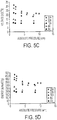
- FIG. 6A-6D shows measured values of CO 2 rate density (slpm/m 2 ) (FIG. 6A), efficiency (FIG. 6B), voltage (Volts) (FIG. 6C), and energy (kJ/molCO 2 ) (FIG. 6D) for KHCO 3 at a pressure of 1 atm, i.e., approximately ambient pressure, for a commercial electrodialysis apparatus from Ameridia, and for a high-pressure electrodialysis apparatus, for example, the embodiment shown in FIG. 2 .
- Efficiency (FIG. 6B) is defined as the number of gas molecules measured per electron charge of current transported; the ideal value is 1 for the case of KHCO 3 where the CO 2 is transported via the singly charged HCO 3 - ion.
- FIG. 6A-6D All results in FIG. 6A-6D are plotted versus current density (mA/cm 2 ) rather than total current to aid in the comparison since the area per membrane is 200 cm 2 for the commercial Ameridia unit, but is approximately 179.74 cm 2 in one embodiment of a high-pressure electrodialysis apparatus.
- Experimental conditions were identical for the two experimental runs: the BPMs, AEMs, and CEMs used were Neosepta BP-1E, Neosepta AHA, Neosepta C66-10F, respectively; acid conductivity was approximately 22 mS/cm and base conductivity was approximately 46 mS/cm; acid pH was approximately 2.6 and base pH was approximately 8.6.
- a two compartment BPMED configuration see FIG.
- FIG. 6B shows that the efficiency of the commercial unit is slightly higher than the high-pressure apparatus, possibly due to the different flow patterns and spacer materials in the two apparatuses. This results in slightly lower CO 2 rate generation density for a given current density in the high-pressure apparatus, as shown in FIG. 6A.
- FIG. 6C shows that for a given current density, the voltage of the high-pressure apparatus is lower than the voltage of the commercial unit. This may be due to the different flow patterns, or may be due to the fact that the membranes used in the high-pressure apparatus were new while those used in the commercial unit had been used for previous experiments.
- the lower voltage and lower efficiency for the high-pressure apparatus combine to yield an energy consumption for a given current density, shown in FIG. 6D, that is approximately identical to the energy consumption of the commercial unit when the high-pressure apparatus is operated at ambient pressure.
- Tables 2-6 show measured values of CO 2 flow (slpm) (Table 2), efficiency (Table 3), voltage (Volts) (Table 4), fractional voltage reduction (Table 5), and energy (kJ/molCO 2 ) (Table 6) for experiments run to characterize the performance of a high-pressure electrodialysis apparatus, such as the embodiment shown in FIG. 2 , at absolute pressures from 1.5 atm to 10 atm.
- Table 2 shows the measured rates at which CO 2 gas evolves from the acid tank after depressurization to 1 atm from absolute pressures of 1.5 atm, 5 atm, and 10 atm at increasing current densities.
- the CO 2 flow increases linearly with increasing current density, with the flow at a given current density being a factor of two higher for KHCO 3 than K 2 CO 3 .
- Table 2 Rate of CO 2 Gas Evolution.
- Table 3 shows the efficiency for absolute pressures of 1.5 atm, 5 atm, and 10 atm at increasing current densities.
- the efficiency is defined as the ratio of molecules of gas evolved per electron charge of current.
- the maximum possible efficiency for KHCO 3 is 1.0, and for K 2 CO 3 is 0.5.
- No data for base solutions of KOH was collected because the CO 2 flow is zero when KOH is used as the base solution.
- Table 3 shows that the efficiency does not depend on pressure. Further, as the current density is increased, the efficiency reaches an asymptotic value of about 0.45 for K 2 CO 3 and 0.85 for KHCO 3 .
- Table 3 Efficiency.
- Table 4 shows the measured voltage for absolute pressures of 1.5 atm, 5 atm, and 10 atm at increasing current densities. Table 4 shows that 1) for a given current density and base solution, the total voltage across the electrodialysis stack decreases with increasing absolute pressure; and 2) the magnitude of this decrease is larger for base solutions of K 2 CO 3 and KHCO 3 than it is for KOH.
- Table 5 shows the fractional voltage reduction at pressure p relative to the voltage measured at 1.5 atm, determined by the formula (V 1.5atm -V p )/V 1.5atm .
- Table 5 shows that 1) while the fractional reduction for K 2 CO 3 and KHCO 3 is about 20% and 15% respectively at high current densities, the reduction for KOH is at most 5%; and 2) the fractional voltage reduction increases with increasing current density. Both of these observations can be explained by the fact that the effect of increasing the absolute pressure of the electrodialysis system is to decrease the amount of CO 2 gas that evolves out of solution inside the electrodialysis stack.
- Table 4 Voltage.
- the CO 2 instead comes out of solution when the acid solution is depressurized to approximately 1 atm or to some pressure between the ambient pressure and the pressure of the electrodialysis apparatus, and in the acid tank that is physically separated from the electrodialysis stack.
- the fractional reduction is greater for KHCO 3 than for K 2 CO 3 at a given current density because the CO 2 transport rate for KHCO 3 is higher than that for K 2 CO 3 at a given current density.
- the reduction for KHCO 3 and K 2 CO 3 is much larger than for KOH because no CO 2 evolution occurs for KOH; the small reduction observed for KOH is likely due to increased chemical activity at the electrodes due to the increased absolute pressure.
- FIG. 9A-9D shows measured values of CO 2 flow (slpm) (FIG. 9A), efficiency (FIG. 9B), voltage (Volts) (FIG. 9C), and energy (kJ/molCO 2 ) (FIG. 9D) for experiments characterizing the performance of a high-pressure electrodialysis apparatus, such as the embodiment shown in FIG. 2 , at currents of 4A, 8A, 16A, 22A, and 25A. Each experimental run was performed at a constant current density, with the pressure being increased until the asymptotic value of voltage was reached. Although 25A was the highest current allowed by the embodiment experimental setup, it will be appreciated that higher currents may be possible with other embodiments.
- the membrane area for each membrane in this experiment was approximately 180 cm 2 , meaning that 25A corresponds to a current density of 139 mA/cm 2 .
- the following conditions were used: the BPMs, AEMs, and CEMs used were Neosepta BP-1E, Neosepta AHA, and Neosepta C66-10F, respectively; base solutions of KHCO 3 were 0.5 M with pH of approximately 8.6; all electrode solutions were 2M KOH; all acid solutions were 0.3 M KH 2 PO 4 and 30 mL of H 3 PO 4 per 5 L of DI water with pH of approximately 2.6.
- the volumetric flow rates through the high-pressure electrodialysis unit were 2.33 lpm for the acid and base solutions and 6.9 lpm for the electrode solution.
- the experiments investigated base solutions of 0.5M KHCO 3 at pressures from 1.5 atm to 10.2 atm.
- FIG. 10A shows a plot of the measured rate at which CO 2 gas evolves from the acid tank after depressurization to 1 atm versus absolute pressure (atm).
- FIG. 10B shows a plot of the efficiency versus absolute pressure for the same data points. The efficiency is defined as the ratio of molecules of gas evolved per electron charge of current.
- FIG. 10A shows that the CO 2 flow is greater at all pressures as the current density increases, an approximately linear increase.
- FIG. 10B shows that a slightly higher than linear increase in CO 2 flow at high current densities results from a slightly increasing efficiency with increasing current density.
- FIG. 10C shows a plot of the measured voltage versus absolute pressure for five different values of total current: 4A, 8A, 16A, 22A, and 25A.
- FIG. 10C shows that 1) for a given current density and base solution, the total voltage across the electrodialysis stack decreases with increasing absolute pressure; 2) the magnitude of this decrease is larger for higher current densities; and 3) for a fixed current density, the voltage asymptotically approaches a minimum voltage with increasing pressure.
- the asymptotic behavior of the voltage with increasing pressure is because for each CO 2 transport rate, i.e., for each current density at some efficiency, there is a pressure where all the transported CO 2 will remain in solution; increasing the pressure above this point should have no additional effect.
- FIG. 10C also shows that for a given current density, and therefore a given rate of CO 2 transport, increasing the pressure reduces the total voltage across the stack via reduction of the resistance by reducing the volume of gas bubbles that come out of solution inside the membrane stack itself.
- the CO 2 instead comes out of solution when the acid solution is depressurized to 1 atm in the acid tank that is physically separated from the membrane stack.
- the reduction increases for increasing current density because the CO 2 transport rate increases with current density.
- the reduction reaches an asymptotic limit as the pressure is increased because above some pressure, all the CO 2 remains dissolved in solution.
- FIG. 10D shows a plot of the energy per molCO 2 versus pressure for five values of current density.
- the membrane area of the membranes in an apparatus is approximately 180 cm 2 , so a current of 25A corresponds to a current density of approximately 140 mA/cm 2 .
- FIG. 10D shows that increased pressure reduces the voltage required for a fixed rate of CO 2 generation.
- the required energy per mol of CO 2 is reduced as the pressure is increased due to the suppression of gas bubble evolution inside the electrodialysis stack.
- the energy required at 10.2 atm, or 333 kJ/molCO 2 is about 30% less than the energy required at 1.5 atm, or 471 kJ/molCO 2 .
- increasing pressure results in a larger and larger fractional reduction of the energy consumption compared to operation at 1 atm.
- a high-pressure electrodialysis system allows for energy-efficient, high-rate concentration of gas, for example, CO 2 , in a compact, reliable unit.
- gas for example, CO 2
- a high-pressure electrodialysis system includes active pH control (pH base - pH acid ⁇ 7) for energy efficient CO 2 separation, and high current densities ( ⁇ 100mA/cm 2 ) in a gas-evolving system enabled by the high-pressure operation.
- active pH control pH base - pH acid ⁇ 7
- high current densities ⁇ 100mA/cm 2
- a high-pressure electrodialysis system allows for the energy consumed per mol of CO 2 generated for a given flow rate to be minimized. For example, if a certain volumetric flow rate of CO 2 is desired, the energy consumed per mol of CO 2 regenerated can be minimized by 1) using a base solution where all the CO 2 is contained in the form of bicarbonate (HCO 3 - ) ions, for example, KHCO 3 ; 2) using a base solution where the concentration of HCO 3 - ions is 0.5M; 3) operating at an electrodialysis stack pressure of at least 10 atm absolute pressure; and 4) setting the current density applied across the membrane stack to match the desired CO 2 volumetric flow rate.
- HCO 3 - bicarbonate
- a high-pressure electrodialysis system also allows for the voltage to be minimized given a fixed current density. For example, for a fixed current density and other fixed parameters such as solution concentrations and flow rates, the voltage can be minimized by operating at a sufficiently large electrodialysis stack pressure. For a given set of parameters, as the absolute pressure of the electrodialysis stack is increased above 1 atm, the voltage decreases, until at some threshold voltage any additional pressure increases no longer affect the voltage. The value of this threshold voltage will depend on the values of the other process conditions, and is directly related to the volumetric rate of CO 2 gas regeneration.
- the CO 2 regeneration is performed by a gas/liquid separation of the CO 2 from the solvent.
- the CO 2 regeneration is performed by high-pressure electrodialysis followed by a liquid/liquid or liquid/supercritical fluid separation of the CO 2 from the solvent.
- solutions that evolve gases other than CO 2 may be used.
- SO 2 gas can be produced when aqueous sulfite or bisulfate solutions are input into the system and made more acidic via operation of the system; and NH 3 gas can be produced when aqueous ammonium solutions are input into the system and made more basic via operation of the system.
- a gas is absorbed into an aqueous solution at some pressure p low .
- High-pressure electrodialysis is then performed on the solution, and then the same gas is regenerated at a pressure p high with p high > p low .
- the embodiments may be used as a novel gas pressurization process capable of replacing inefficient mechanical compressors.
- the first and second solutions are held at an approximately constant pH.
- the present invention relates to a process for producing a gas using an electrodialysis apparatus comprising: flowing at least a first solution and a second solution into the electrodialysis apparatus, wherein the first solution is a basic solution and the second solution is an acidic solution or wherein the first solution is an acidic solution and the second solution is a basic solution, wherein the electrodialysis apparatus comprises an anode end (201) and a cathode end (202), a housing which comprises axial support members (203), and reinforcing members (204) which are configured to apply a compressive force in the axial direction when they are coupled together, wherein the axial support members (203) are mated together to form a cell chamber in which an eletrodialysis membrane stack (205) is received; flowing an electrode solution into the electrodialysis apparatus; pressurizing the electrodialysis apparatus at a stack pressure; applying a voltage to an electrodialysis stack of the electrodialysis apparatus such that the product is a dissolved gas is generated in the
Description
- The concentration of atmospheric carbon dioxide (CO2) continues to rise, as shown by, for example, IPCC, Climate Change 2007: Synthesis Report. Contribution of Working Groups I, II and III to the Fourth Assessment Report of the Intergovernmental Panel on Climate Change, 2007 [Core Writing Team, Pachauri, R.K and Reisinger, A. (eds.)], IPCC, Geneva, Switzerland, 104 pp. It is becoming increasingly imperative to invent efficient and cost-effective technologies for controlling the atmospheric CO2 concentration. The concentration of atmospheric carbon dioxide (CO2) is rising at the rate of approximately 2 parts per million per year (ppm/yr). The challenge of reducing the concentration of atmospheric CO2 represents an opportunity to invent new, cost-effective technologies to solve this problem.
- Techniques for removing CO2 from streams of mixed gases, such as removing the CO2 from power-plant flue-gas emissions or removing CO2 from the atmosphere, typically involve a two-step process of capture and regeneration. First, the gas is contacted with an aqueous "pre-capture solution" that reacts with the CO2 gas in the mixed-gas stream, "capturing" the CO2 into what is then referred to as a "post-capture solution." Next, a stream of pure CO2 gas is regenerated from this CO2-rich aqueous post-capture solution. Various pre-capture solutions exist, with different solutions being preferred depending on the concentration of CO2 in the mixed gas source. For mixed gas streams with low concentrations of CO2-such as the atmosphere with a CO2 concentration of 386 ppm as of 2009 as shown by Dr. Pieter Tans, NOAA/ESRL (www.esrl.noaa.gov/gmd/ccgg/trends)-aqueous hydroxide pre-capture solutions such as potassium hydroxide (KOH) or sodium hydroxide (NaOH), aqueous carbonate pre-capture solutions such as potassium carbonate (K2CO3) or sodium carbonate (Na2CO3), or aqueous bicarbonate pre-capture solutions such as potassium bicarbonate (KHCO3) or sodium bicarbonate (NaHCO3) are likely candidates for CO2 pre-capture solutions. Other pre-capture solutions are known, for example, monoethanolamine (MEA), which is used in gas stream scrubbing applications to remove, for example, CO2 from flue gas. The capture of CO2 gas into these pre-capture solutions converts the original hydroxide/carbonate/bicarbonate pre-capture solutions into a more acidic post-capture solution consisting of a mixture of hydroxide (KOH or NaOH), carbonate (K2CO3 or Na2CO3), and/or potassium bicarbonate (KHCO3) or sodium bicarbonate (NaHCO3) post-capture solutions, as examples.
- Once the CO2 gas is captured from the mixed-gas stream into the pre-capture solutions in the ionic forms CO3 (2-) and/or HCO3 - to form the post-capture solutions, pure CO2 gas is typically regenerated from the solution. The overall effect of this process of capture and regeneration is the separation and concentration of CO2 gas from a pre-separation mixed-gas stream with a relatively low mole fraction of CO2 gas into a post-separation gas stream that possesses a higher mole fraction of CO2 gas than the pre-separation stream. Under the right conditions, the mole fraction of CO2 in the post-separation stream may be unity, that is, the post-separation stream may be a pure stream of CO2 gas. After capture and regeneration, the post-separation gas can then be, for example, geologically sequestered, or incorporated into useful products such as concrete, as shown by Calera, Green Cement for a Blue Planet, http://www.calera.com/index.php/technology/technology_vision/ (last visited Sept. 9, 2010); plastics, as shown by G.A. Olah et al., Beyond Oil and Gas: The Methanol Economy, Wiley-VCH (2006); or liquid hydrocarbon fuels, as shown by F.S. Zeman & D.W. Keith, Carbon Neutral Hydrocarbons, Phil. Trans. R. Soc. A, 366, 3901-3918 (2008), and PARC, Renewable Liquid Fuels, http://www.parc.com/work/focus-area/renewable-liquid-fuels/ (last visited Sept. 9, 2010). Many of the possible uses of the regenerated CO2, such as sequestration or reaction to liquid fuels, for example, require the pressurization of the CO2 to pressures greater than 1 atm.
- Bipolar membrane electrodialysis (BPMED) can be used to convert aqueous salt solution into acids and bases without the addition of other chemicals. A component of BPMED devices is ion exchange membranes used to separate ionic species in solution when an electrical field is applied across the membranes. Performing BPMED on certain solutions may create gas bubbles adjacent to the membrane surface that can block ion transport and reduce the effective membrane surface area, causing increased cell resistance and localized "hot spots" of very high current density that lead to shortened membrane lifetimes. As a result, commonly used input and output solutions are selected so that they do not evolve significant quantities of gas inside the membrane stack at ambient pressure, which excludes an entire class of gas-evolving solutions from electrodialytic treatment. Example embodiments address these and other disadvantages of the conventional art.
-
EP2163294A1 discloses a system and method for recovery of CO2 by utilizing a process for producing gas with an electrodialysis apparatus. -
-
FIG. 1 is a schematic of an embodiment of a high-pressure electrodialysis system. -
FIG. 2 is an exploded view of an embodiment of a high-pressure electrodialysis apparatus for use in a high-pressure electrodialysis system. -
FIG. 3 is a schematic of electrodialysis membrane stack operation for generating CO2 gas according to an embodiment. -
FIG. 4 is a schematic of electrodialysis membrane stack operation for generating CO2 gas according to an embodiment. -
FIG. 5 is an example demonstration of steady-state data collection methodology. - FIG. 6 is a comparison of experimental results for 0.5 M KHCO3 flowed through an embodiment of a high-pressure electrodialysis apparatus operating at 1 atm and a commercial system operating at 1 atm.
- FIG. 7 is a comparison of experimental results for 0.5 M K2CO3 flowed through an embodiment of a high-pressure electrodialysis apparatus operating at 1 atm and 5 atm.
- FIG. 8 shows the percent decrease in the measured total voltage of an embodiment of a high-pressure electrodialysis system operating at 5 atm compared to the voltage of an embodiment of a high-pressure electrodialysis system operating at 1 atm, plotted as a function of CO2 rate density, when 0.5 M K2CO3 is flowed through the system.
- FIG. 9 shows measured values of experiments designed to characterize the performance of an embodiment of a high-pressure electrodialysis apparatus at currents of 4A, 8A, 16A, 22A, and 25A for a 0.5 M KHCO3 solution.
- Currently available bipolar membrane electrodialysis (BPMED) apparatuses include an electrodialysis stack made up of at least one electrodialysis cell. The electrodialysis cell includes at least one bipolar membrane (BPM) such that, when an electrical potential is applied across the cell, the dissociation of water into hydrogen (H+) and hydroxide (OH-) ions occurs.
- A BPM is formed from a cation-exchange layer laminated together with an anion-exchange layer, as well as a junction layer between the cation and anion layers. Water diffuses into the junction layer, reaching the usual equilibrium with H+ and OH- ions according to its dissociation constant. Typically, a BPM is oriented such that the anion-exchange layer faces the anode (positive electrode) end of the BPMED apparatus and the cation-exchange layer faces the cathode (negative electrode) end of the apparatus. This orientation allows the OH- ions to be transported across the anion-exchange layer and the H+ anions to be transported across the cation-exchange layer when an electrical potential is applied across the membrane stack. Simultaneously, the constituent cations and anions of an input salt solution are separated under the applied electrical potential via ion exchange membranes-either anion exchange membranes (AEMs), cation exchange membranes (CEMs), or some combination of the two. The OH- (H+) ions "produced" by the BPM then combine with the cations (anions) separated from the input salt solution to produce basic (acidic) output solutions containing the parent acid and base of the input salt. Depending on the membrane configuration, a diluted salt solution may also be produced as output in addition to the acid and base output solutions.
- A BPMED membrane stack can have either a two-compartment or a three-compartment configuration. In a two-compartment configuration, adjacent membranes may alternate between BPM and AEM to form a membrane stack of the form BPM, AEM, BPM, AEM, etc.; or adjacent membranes may alternate between BPM and CEM to form a membrane stack of the form BPM, CEM, BPM, CEM, etc. In a three-compartment cell, adjacent membranes may cycle from BPM to AEM to CEM, forming a membrane stack of the form BPM, AEM, CEM, BPM, AEM, CEM, etc. Electrodialysis without bipolar membranes is also possible, and consists of a two-compartment configuration formed by an alternating series of AEM and CEM to form a membrane stack of the form AEM, CEM, AEM, CEM, AEM, etc.
- As mentioned above, gas bubbles inside commercially available BPMED systems result in gas bubbles adjacent to the membrane surface that can block ion transport in this region and reduce the effective membrane surface area, resulting in increased resistance and localized "hot spots" of very high current density that lead to shortened membrane lifetimes. As a result, commonly used input and output solutions are selected so that they do not evolve significant quantities of gas inside the membrane stack at ambient pressure. This excludes an entire class of gas-evolving solutions from electrodialytic treatment.
- In an embodiment, these challenges are overcome by operating an electrodialysis apparatus at high pressure, i.e., above ambient pressure. In an embodiment, the operating pressure is sufficiently high, given other process conditions, that a gas that would typically evolve out of solution into the membrane stack at ambient pressure instead remains dissolved in solution, preventing gas bubble evolution inside the membrane stack itself. In an embodiment, the pressure of the solution containing the dissolved gas can be reduced downstream of the membrane stack so that the dissolved gas evolves out of solution and can be collected for other uses, if desired. In an embodiment, the pressure to which the solution is reduced can be any pressure less than the operating pressure of the membrane stack. In this way, the gas can be evolved at pressures greater than ambient pressure, and can also be evolved at pressures less than ambient pressure, if desired. Electrodialysis apparatuses according to certain embodiments may allow, for example, for energy-efficient, high-rate concentration of CO2 in a compact, reliable unit from the aqueous carbonate/bicarbonate capture solutions to pure or nearly pure CO2 gas suitable, for example, to sequester, to incorporate into useful products, or to react with other inputs to synthesize liquid hydrocarbon fuels.
- It will be understood that whether gas, liquid, supercritical fluid, or some combination thereof is generated using embodiments of the process described herein depends on 1) the temperature and pressure at which the electrodialysis is performed, and 2) the input solution composition. For example, when input solutions containing CO2 are used, either CO2 gas, CO2 liquid, or supercritical CO2 may be generated, depending on the temperature and pressure used. When the operating pressure and temperature fall on the gas portion of the CO2 phase diagram, for example at a pressure of approximately 10 atm and a temperature of approximately 20°C, CO2 is generated in the output solution as a gas. When the operating pressure and temperature used fall within the liquid portion of the CO2 phase diagram, for example approximately 100 atm and 20°C, CO2 liquid is generated. When the operating pressure and temperature are high enough to pass the critical point of CO2, for example approximately 75 atm and 35°C, supercritical CO2 fluid is generated. In any of these cases, the CO2 gas, liquid, or supercritical fluid can be regenerated from the output solution by known methods, such as gas/liquid, liquid/liquid or liquid/supercritical fluid separation. It will be understood that other gas, liquid, or supercritical fluid products besides CO2, such as SO2 or NH3, can be generated using high-pressure electrodialysis, depending on the input solution used. The temperature of the electrodialysis process may be controlled by, for example, direct heating of the input solutions.
- In some embodiments, a gas is absorbed into aqueous solution at some pressure plow High-pressure electrodialysis is then performed on the solution, and then the same gas is regenerated at a pressure phigh with phigh > plow. In this way, the embodiments may be used as novel gas pressurization devices capable of replacing inefficient mechanical compressors.
- By pressurizing the solutions (electrode, first, second, and any third solutions) in the stack and then performing ion transport into a solution from which gas evolves, pressurization is accomplished more efficiently than with standard processes. In the case of CO2, this allows direct generation of CO2 at the pressures required for certain uses of the regenerated CO2, such as sequestration and reaction to a liquid fuel, for example. This may also be a benefit for other gases that could be directly regenerated at the elevated pressure required for a subsequent reaction step. For example, SO2 gas can be produced when aqueous sulfite or bisulfate solutions are input into the system and made more acidic via operation of the system, and NH3 gas can be produced when aqueous ammonium solutions are input into the system and made more basic via operation of the system.
- Processes to generate gas using high-pressure electrodialysis disclosed here reduce the energy consumption of electrodialysis of gas-evolving solutions, especially at the high current densities typically desired for real-world application. Embodiment processes also reduce the voltage across the electrodialysis membrane stack for electrodialysis of gas-evolving solutions, especially at the high current densities typically desired for real-world application.
- Electrodialytic generation of CO2 has the potential to be less destructive to and more compatible with the homogenous catalysts for CO2 capture than thermal/chemical regeneration methods. It also has the potential to be less capital intensive and space-consuming than thermal/chemical regeneration methods, and to be more easily scaled down for mobile applications, such as military fuel generation, than thermal/chemical regeneration methods.
-
FIG. 1 is a schematic of an embodiment of a high-pressure electrodialysis system. The system includes an apparatus for conducting two-compartment electrodialysis consisting of three different loops: one for a first solution loop, one for a second solution loop, and one for an electrode solution loop. In another embodiment, the system includes an apparatus for conducting three-compartment elctrodialysis includes consisting of four different loops: one for a first solution, one for a second solution, one for a third solution, and one for an electrode solution loop. AlthoughFIG. 1 depicts a system with three loops such that an apparatus for conducting two-compartment BPMED or electrodialysis without bipolar membranes can be incorporated in the system, it will be appreciated that the system can be adapted to instead incorporate a three-compartment BPMED apparatus by incorporating an additional loop for a third solution. - In an embodiment, the first solution is a basic solution and the second solution is an acidic solution. In an embodiment, the first solution is an acidic solution and the second solution is a basic solution. An electrode solution may be, for example, an electrolyte. In an embodiment incorporating four loops, the third solution may be, for example, a salt solution that is diluted upon passing through the operating electrodialysis unit.
- Each loop can be operated in either bypass or stack mode. When a loop operates in bypass mode, the solutions bypass the electrodialysis membrane stack of the high-
pressure electrodialysis apparatus 110. Each loop includes one or more tanks (for example, first solution tank 100), a pump (for example, first solution pump 104), a pulsation dampener (for example, first solution pulsation dampener 107), one or more temperature and pH meters (for example, meter 116), one or more temperature and conductivity meters (for example, meter 117), one or more pressure and flow meters (for example,meters 123 and 123), valves to change the operation mode between bypass mode and stack mode (for example,valves 112 and 120), and a valve to adjust the pressure of the electrodialysis apparatus 110 (for example, valve 121). - In an embodiment, the high-pressure electrodialysis system also includes a high-
pressure electrodialysis apparatus 110. -
FIG. 2 shows an exploded view of a high-pressure electrodialysis apparatus for use in a high-pressure electrodialysis system according to an embodiment. The high-pressure electrodialysis apparatus includes an anode (held at a positive electrical potential relative to the cathode)end 201 and a cathode (held at a negative electrical potential relative to the anode)end 202. The apparatus includes a housing that includesaxial support members 203 and reinforcingmembers 204. When the apparatus is assembled, theaxial support members 203 are mated together to form a cell chamber in which anelectrodialysis membrane stack 205 is received. The reinforcingmembers 204 are configured to apply a compressive force in the axial direction when they are coupled together, for example, by a bolted connection, such that theaxial support members 203 are mated and the electrodialysis apparatus can operate at pressures above ambient pressure, ambient pressure being defined as the pressure naturally occurring in the environment surrounding the apparatus. At an elevation of sea-level, the ambient pressure is typically around 1 atm, or 101.325 kPa. For example, in an embodiment, the high-pressure electrodialysis apparatus can operate at pressures up to and including 20 atm. In an embodiment, the high-pressure electrodialysis apparatus can operate at pressures above 20 atm. In an embodiment, theaxial support member 203 at theanode end 201 includes at least onepressurization port 216. Thepressurization port 216 allows the pressure between the interior of theelectrodialysis membrane stack 205 and the cell chamber formed by the mating ofaxial support members 203 to equalize by diverting a portion of the electrode solution into the region of the cell chamber outside theelectrodialysis stack 205. - The
electrodialysis stack 205 includes one ormore electrodialysis cells 206. Theelectrodialysis stack 205 may include one ormore cells 206 configured to carry out electrodialysis without bipolar membranes, or one or more cells configured to carry out BPMED. Cells configured to carry out BPMED may be either two-compartment or three-compartment cells. For example, theelectrodialysis cell 206 inFIG. 2 includes twocell gaskets 207 arranged in alternating order with first and secondion exchange membranes cell 206 could carry out electrodialysis without bipolar membranes if, for example, firstion exchange membrane 208 was an AEM and secondion exchange membrane 209 was a CEM. Alternatively, the cell could carry out BPMED if, for example, firstion exchange membrane 208 was a BPM, and secondion exchange membrane 209 was an AEM or a CEM. It will be recognized that other configurations of membrane types may be possible, depending on input solutions used and the desired output solution. - The
electrodialysis stack 205 may also includeend gaskets 211 at one or both ends of the stack, endion exchange membranes 210 at one or both ends of the stack, and anadditional cell gasket 212 interposed between thenth electrodialysis cell 206 and the endion exchange membrane 210 at thecathode end 202 of themembrane stack 205. It will be recognized that whether endion exchange membranes 210 and anadditional cell gasket 212 are needed, and what types ofion exchange membranes 210 are appropriate, depends on the input solutions used and the desired output solution. -
FIG. 3 shows a schematic of electrodialysis membrane stack operation used to generate CO2 gas in a high-pressure electrodialysis apparatus that contains one two-compartment BPMED cell. Although CO2 generation is depicted, it will be understood that other gases may be generated using the illustrated stack configuration and process, depending on the inputs into the system. - Turning to
FIG. 3 , in anelectrodialysis stack 301 that includes one two-compartment BPMED cell 302, theelectrodialysis cell 302 is composed of twocell gaskets ion exchange membranes cell gaskets electrodialysis stack 301 also includes two endion exchange membranes electrodialysis cell 302 is interposed between the two endion exchange membranes additional cell gasket 309 interposed between the secondion exchange membrane 306 of theelectrodialysis cell 302 and the second endion exchange membrane 308. Theelectrodialysis stack 301 also includes twoend gaskets first end gasket 310 is interposed between theanode end electrode 312 of the apparatus and the first endion exchange membrane 307, and thesecond end gasket 311 is interposed between thecathode end electrode 313 of the apparatus and the second endion exchange membrane 308. - In an embodiment where the electrodialysis stack is configured to perform two-compartment BPMED, the first
ion exchange membrane 304 is a BPM, the secondion exchange membrane 306 is an AEM, and the endion exchange membranes first CEM 307 and theBPM 304, and an acidic solution (pH < 7) is generated between theBPM 304 and theAEM 306. Depending on system parameters, such as the concentration of dissolved species, pH, and absolute pressure, gas may evolve out of the acidic solution between theBPM 304 and theAEM 306, or the gas may remain dissolved in the acidic solution. For example, when CO2 gas is dissolved in the acidic solution, for a given concentration of dissolved CO2 and a given pH of the acidic solution, if the pressure is sufficiently high all the CO2 gas will remain dissolved in solution. As an example, the input aqueous solutions are an electrode solution of KOH flowing between theanode 312 and theend CEM 307 in the solution compartment defined bygasket 310 and also flowing between thecathode 313 and theend CEM 308 in the solution compartment defined bygasket 311; a base solution of KHCO3 and K2CO3 flowing between theend CEM 307 andBPM 304 in the solution compartment defined bygasket 303 and also flowing between theAEM 306 and theend CEM 308 in the solution compartment defined bygasket 309; and an acid solution of KH2PO4 and H3PO4 flowing between theBPM 304 and theAEM 306 in the solution compartment defined bygasket 305. Under such conditions, K+ ions are transferred acrossend CEM 307 from the electrode solution in the compartment defined bygasket 310; OH- and H+ ions are dissociated across theBPM 304; and HCO3 - and CO3 2- are transferred acrossAEM 306 from the basic solution in the compartment defined bygasket 309. The K+ ions combine with the dissociated OH- ions to generate KOH between thefirst CEM 307 and theBPM 304; the H+ ions combine with HCO3 - and CO3 2- ions to form H2CO3 and dissolved CO2 in the solution compartment defined bygasket 305 between theBPM 304 and theAEM 306. - In an embodiment, the
electrodialysis stack 205 includes more than one two-compartment cell. In an embodiment, the electrodialysis stack includes, for example, seven two-compartment cells. The electrodialysis apparatus can be adapted to receive any other number of cells. In another embodiment, the cell is not configured to perform BPMED, but rather performs electrodialysis without bipolar membranes. For example, the firstion exchange membrane 304 may be an AEM, and the secondion exchange membrane 306 may be a CEM. - In an embodiment, the electrodialysis stack includes one or more three-compartment cells instead.
FIG. 4 shows a schematic of electrodialysis stack operation to generate CO2 gas in a high-pressure BPMED apparatus that contains one three-compartment cell. Although CO2 generation is depicted, it will be understood that other gases may be generated using the illustrated stack configuration and process, depending on the inputs into the system. - Turning to
FIG. 4 , in an embodiment of anelectrodialysis stack 401 that includes one three-compartment electrodialysis cell 402, theelectrodialysis cell 402 is composed of threecell gaskets ion exchange membranes cell gaskets electrodialysis stack 401 also includes twoend gaskets first end gasket 411 is interposed between theanode end electrode 413 of the apparatus and the endion exchange membrane 409, and thesecond end gasket 412 is interposed between thecathode end electrode 414 of the apparatus and theelectrodialysis cell 402. Theelectrodialysis stack 401 also includes one endion exchange membrane 409 interposed between theelectrodialysis cell 402 and theend gasket 411. - In such an embodiment, the first
ion exchange membrane 404 is a BPM, the secondion exchange membrane 406 is an AEM, the thirdion exchange membrane 408 is a CEM, and the endion exchange membranes 409 is a CEM. A basic solution is generated between the endion exchange membrane 409 and theBPM 404, an acidic solution and CO2 gas are generated between theBPM 404 and theAEM 406, and a desalted input solution is generated between theAEM 406 and theCEM 408. For example, the input solutions may include an electrode solution of KOH in compartments defined bygaskets gaskets gasket 405. Under such conditions, K+ ions are transferred acrossend CEM 409 from the electrode solution in the compartment defined byend gasket 411 and acrossCEM 408 into the electrode solution in the compartment defined byend gasket 412; OH- and H+ ions are dissociated across theBPM 404; and HCO3 - and CO3 2- are transferred acrossAEM 406 from the basic solution in the compartment defined bygasket 407. The K+ ions combine with the dissociated OH- ions to generate KOH between the endion exchange membrane 409 and theBPM 404; the H+ ions combine with HCO3 - and CO3 2- ions to form H2CO3 and dissolved CO2 in the solution compartment defined bygasket 405 between theBPM 404 and theAEM 406; and a diluted KHCO3 and K2CO3 solution, less concentrated than the input solution, is generated between theAEM 406 and theCEM 408. - In an embodiment, the
electrodialysis stack 401 includes more than one three-compartment cell 402. In an embodiment, theelectrodialysis stack 401 includes, for example, seven three-compartment cells 402. The electrodialysis apparatus can be adapted to receive any other number of cells. - Turning back to
FIG. 2 , the high-pressure electrodialysis apparatus also includes ports, which allow the solutions to flow into and out of the apparatus. The ports may be bossed ports formed in theaxial support members 203 that slide through bossed port holes formed in the reinforcingmembers 204;flange adapters 213 may then be fitted over each bossed port and attached to the reinforcingmembers 204. In an embodiment where theelectrodialysis stack 205 includes one or more non-BPMED or two-compartment BPMED cell, eachend anode end 201, allowing solutions to flow into the apparatus; the corresponding first and second solution ports at thecathode end 202 would be outlet ports, allowing solutions to flow out of the apparatus. The flow of the apparatus can be reversed if desired such that the ports at theanode end 201 are outlet ports and those at thecathode end 202 are inlet ports. In addition, the flow can be such that there is an input port for one solution and an output port for the other solution atanode end 201, and an output port for the solution whose input port is at the anode end and an input port for the solution whose output port is at the anode end, at thecathode end 202. Each end of the apparatus has both an electrode solution inlet port and an electrode solution outlet port. In an embodiment where theelectrodialysis stack 205 includes one or more three-compartment BPMED cells, eachend - The high-pressure electrodialysis apparatus also includes two
electrodes 214, one at either end of theelectrodialysis stack 205, and two electrode grates 215, each interposed between one of theelectrodes 214 and theelectrodialysis stack 205. In an embodiment, the electrodialysis apparatus also includes twostress reduction cylinders 217, one attached to each reinforcingmember 204. - In an embodiment, the electrodialysis apparatus shown in
FIG. 2 is incorporated into the high-pressure electrodialysis system shown inFIG. 1 as theelectrodialysis apparatus 110. When theelectrodialysis apparatus 110 includes a BPMED electrodialysis stack, the electrodialysis system ofFIG. 1 can be used, for example, to regenerate CO2 gas from aqueous carbonate and bicarbonate solutions. Depending on system parameters, such as the concentration of dissolved species, pH, and absolute pressure, gas may evolve out of solution inside the electrodialysis apparatus, or the gas may remain dissolved in the solution until the solution is no longer inside the electrodialysis apparatus. For example, for a given concentration of dissolved CO2 and a given pH of the solution, if the pressure is sufficiently high, all the CO2 gas will remain dissolved in solution. The pressure can then be decreased when the solution is no longer inside the electrodialysis apparatus, resulting in the evolution of CO2 gas out of solution. This prevents the evolution of gas inside the apparatus, thereby avoiding the deleterious effects of gas evolution inside the apparatus such as increased voltage and energy consumption, and localized "hot spots" of high current density that can lead to membrane damage and/or reduced membrane lifetimes. - Turning back to
FIG. 1 , in an embodiment, tanks 100-103 of the high-pressure electrodialysis system are designed to withstand pressures up to approximately 20 atm with a safety factor of about 3. The tanks 100-103 can be pressurized to any pressure between ambient pressure and the absolute pressure of the electrodialysis stack. When the tanks are so pressurized, gas evolves out of solution at a pressure above ambient pressure, i.e., at a pressure substantially the same as the pressure of the tanks 100-103. In an embodiment, the covers of the tanks 100-103 have three threaded holes of a diameter of ¼ inch for optional pipe connections and a fill cap of a diameter of 1 1/8 inch to fill the tanks 100-103. - In an embodiment, the first and
second solution tanks 100 and 101 each have both an inlet coming from the bypass or theelectrodialysis apparatus 110 and an outlet going to thefirst solution pump 104 orsecond solution pump 105 respectively. Bothtanks 100 and 101 have a feed-through where the pH and theconductivity meters second solution tank 101 is equipped with a vent and a 1/8 inch pipe for gas infusion. In an embodiment, the first solution tank 100 has two windows to observe the evolution of gas bubbles from the solution. In an embodiment where the tank is pressurized, the tank cover may be equipped with a pressure sensor to know the pressure of the tank. The tank may also be equipped with two vents: one that leads the gas to a valve and a flow meter in order to regulate and measure the flow of gas evolving from the solution, and one to empty the headspace and flush the tank with gas. - In an embodiment, the first and
second solution tanks 100 and 101 both have meters for measuring, showing, and recording certain information about the tank conditions. For example, the first solution tank 100 may include a temperature and pH information and recording to computer (TXIR)meter 116 that measures, shows, and records the temperature and pH of the first solution. The first solution tank 100 may also include aTXIR meter 117 that measures, shows, and records the temperature and conductivity of the first solution. Thesecond solution tank 101 may also have aTXIR meter 116 andTXIR meter 117 that perform the same functions for the second solution. - In an embodiment, the
second solution tank 101 may also have a means for infusing gas into the second solution in order to regenerate the gas while operating through the electrodialysis stack. For example, in an embodiment electrodialysis system that is used to generate CO2 gas, thesecond solution tank 101 may be a base solution tank that has a CO2 gas bottle connected to it by, for example, a 1/8 inch pipe. The infusion of gas into thefirst solution tank 101 can be turned on or off usingvalve 118. - In an embodiment, the first solution loop also includes a
valve 119 to drain the first solution loop and avalve 120 to change the operation from the bypass to the electrodialysis stack mode. The second solution loop also includesvalves valve 121 to change the pressure in the electrodialysis system and avalve 122 for taking samples. The second solution loop also includesvalves meter 123 and flow information and recording to computer (FIR)meter 124, respectively. The second solution loop also includesPIR meter 123 andFIR meter 124 that perform the same functions with respect to the second solution loop. - In an embodiment, the electrode solution loop has two tanks 102-103. Each tank 102-103 has an inlet coming from the bypass or the
electrodialysis apparatus 110 and an outlet going to theelectrode solution pump 106. Theelectrode solution tank 102 is for the electrode solution coming from theanode end 201 of the electrodialysis apparatus 110 (seeFIG. 2 ) from where oxygen will evolve. Theelectrode solution tank 103 is for the fluid coming from thecathode end 202 of the electrodialysis apparatus 110 (seeFIG. 2 ) from where hydrogen will evolve. In an embodiment, each tank 102-103 is equipped with a pipe connection that has a ¼ inch barb fitting to vent the tanks from the evolving gases. The vent oftank 103 may be connected to the building exhaust to avoid high H2 concentrations in the atmosphere. - In an embodiment, the electrode solution loop also has a
valve 111 to drain the electrode solution loop. It may also include twovalves 112 to change the operation from the bypass to the electrodialysis stack mode. It may also include twovalves 113 that can be varied in order to change the pressure in the electrodialysis system. In an embodiment, the pressure and flow of the electrode solution loop are measured and recorded byPIR meter 114 andFIR meter 115, respectively. - In an embodiment, each port of the electrodialysis apparatus 110 (see
FIG. 2 ) is equipped withcheck valves 128 to avoid the flow of any solution into theelectrodialysis apparatus 110 while the system operates in the bypass mode. Each loop has apulsation dampener 107 to damp the pressure oscillation caused by the operation of the positive displacement pumps 104. - In an embodiment, the electrodialysis system includes
valve 131, a three-way valve connected to a house vacuum. Before the electrodialysis system is used,valve 131 can be alternately opened and closed withvalve 118, which is connected to a cylinder of whatever gas the system is being used to generate, for example, CO2. Doing so purges the headspace of first solution tank 100 of air so that the headspace contains nothing but whatever gas the system is being used to generate, for example, CO2. Purging the headspace in this manner ensures that all the gas that flows throughFIR meter 130 is pure, or as close to pure as possible, which ensures accurate measurements of the gas flow byFIR meter 130. - In an embodiment, the electrodialysis system includes
motors 125, one motor for each of the first, second, and electrode solution loops. It also includes Hz/RPM controllers 126, one each for the first, second, and electrode solution loops. It also includespressure relief valves 127, one each for the first, second, and electrode solution loops. It also includesvalve 132, a two-way valve that allows the operator of the system to connect or block the flow from the vacuum or gas cylinder; which is blocked depends on the settings ofvalve 131 andvalve 118. It also includesvalve 133, a needle valve for controlling the gas flow throughFIR meter 130. The electrodialysis system also includes adrain 129 to receive any solution drained from tanks 100-103 via theirrespective valves - In an embodiment, the values of each measuring position of the system are read and recorded every five seconds by computer software. These values can be saved and recalled when desired. Table 1 summarizes the measuring positions of one embodiment of a system and their functions. Other measurement positions not shown on the schematic are those that measure the voltage and current going through the membrane stack.
Table 1: Measuring Positions and their Functions Measuring Position Function Input/ Output FIR meters 115, 124 Measure, show, and record the flow of the loop Input PIR meters 114, 123 Measure, show, and record the pressure of the loop Input TXIR meters 116, 117 Measure, show, and record the temperature and either the pH or the conductivity of the base or acid solution Input FIR meter 130 Measures, shows, and records the flow of the gas evolving from the acid tank Input VFD meters 126 Record and control the frequency or RPM of the motor. Builds a control loop with the FIR to control the flow of the loop. Output - In an embodiment, the electrodialysis system of
FIG. 1 can be constructed with the following: positive displacement pumps (model M03SASGSSEMA pump from HydraCell); variable frequency motor drives (model VS1SP61-1B VFD from Baldor); motors (model IDNM3583 from Baldor); pulsation dampeners (model 110-065 from HydraCell); pressure relief valves (model RV2MF-6N-A-S316 from Hy-Lok); flowmeters (model FTB4805 from Omega); pressure sensors (model PX219 from Omega); pH meters (model OrionStar from ThermoScientific); conductivity meters (model OrionStar from ThermoScientific); power supply (model XHR40-25 from Xantrex); gas flow meter (model FMA1605A from Omega); data acquisition module model USB-1616HS-4 from Measurement Computing); RS485 communication card (model PCI4S422DB94PR from StarTech); USB to RS232 multiport convertor (model USB-8COM from VSCOM); stainless steel rack and secondary containment (in house design and outside fabrication); numerous 316SS valves, fittings, hoses, tubing (from McMaster-Carr); acid, base, and electrolyte tanks (in house design and fabrication); high-pressure electrodialysis apparatus; H2 sensor for safety; vent system for exhaust gases; gas tank and regulator for headspace flushing and base gas infusion; and de-ionized (DI) water line for system flushing. - By using an electrodialysis system (see
FIG. 1 ) that incorporates a high-pressure electrodialysis apparatus (seeFIG. 2 ), gas can be produced at any pressure between ambient pressure and the absolute pressure of the electrodialysis stack from any gas-evolving solution. An embodiment of a high-pressure electrodialysis system was tested to determine process conditions for generating CO2 gas from carbonate and bicarbonate solutions. Therefore, the following figures and their accompanying discussion will refer to a process according to one embodiment for generating CO2 gas. However, it will be appreciated that embodiments of the high-pressure electrodialysis system, process, and preferred conditions described herein can be used to generate other gases besides CO2, depending on what solutions are used. For example, SO2 gas can be produced when aqueous sulfite or bisulfate solutions are input into the system and made more acidic via operation of the system; and NH3 gas can be produced when aqueous ammonium solutions are input into the system and made more basic via operation of the system. - The ion transport that occurs in the electrodialysis stack is best understood by describing a process for evolving CO2 gas using a high-pressure electrodialysis system. All experiments performed to determine process conditions were operated in steady-state mode, i.e., where the pH of the acid and base solutions is kept constant, resulting in steady-state behavior for measured quantities such as the rate of CO2 gas evolution from the acid compartment, voltage, and energy consumption. In an experiment, a solution of 0.3M KH2PO4 and 15 mL of H3PO4 in 2.5L of DI water was loaded into the acid tank. A solution of KHCO3, K2CO3, and KOH in 2.5L of DI water was loaded into the base tank; various concentrations of each of these solutes were used for different experimental runs. A solution of 2M KOH in 2.5L of DI water was loaded into the electrode solution tank. Other concentrations of solutions may be used. For example, a concentration of base solution of 0.05 M to 2 M may be used; a concentration of acid solution of 0.05 M to 2 M may be used; and a concentration of electrode solution of 0.1 M to 2 M may be used. However, any concentration for the base, acid, and electrode solutions may be used, including concentrations that are below or above these ranges.
- The pumps of the electrodialysis system (see
FIG. 1 ) were turned on to allow volumetric flow rate velocities of approximately 300L/hr and 140L/hr in the electrode solution and acid/base tanks, respectively. Other flow rate velocities may be used. For example, the electrode solution may have a flow rate velocity between 200L/hr and 600L/hr; the acid and base solutions may have flow rate velocities between 60L/hr and 300L/hr. However, any flow rate velocities for the base, acid, and electrode solutions may be used, including flow rate velocities that are below or above these ranges. - The acid and base solutions are each flowed from their respective tanks and into the high-pressure electrodialysis apparatus, through the electrodialysis stack, and then returned to their respective tanks to be pumped again through the electrodialysis apparatus. The electrode solution is pumped from one electrode solution tank and into the high-pressure electrodialysis apparatus at both the cathode and anode ends, flowed across the electrodes at each end, and then flowed back out of the apparatus at both ends and into a second electrode solution tank. By combining the electrode solution output from both ends of the apparatus into the same electrode solution tank, electroneutrality is preserved. By venting the tanks prior to recombining the solutions, the mixing of H2 and O2 gases is avoided.
- The solutions may be allowed to flow for approximately 5-10 minutes until the pH and conductivity values stabilize after mixing with any water left behind in the setup from flushing the electrodialysis apparatus after any previous run. The high-pressure electrodialysis apparatus is then pressurized to the desired stack pressure via the adjustment of, for example, needle valves. In an embodiment, the stack pressure is any pressure greater than ambient pressure. In an embodiment, the stack pressure is 200 atm or less. As the process of pressurization sometimes causes the acid pH to increase slightly, additional H3PO4 may then be added to the acid tank until the acid pH is approximately 2.5. In this way, active pH control of the electrodialysis system is possible. Although the electrodialysis stack is pressurized at this point, in an embodiment all the tanks remain at ambient pressure. In a separate embodiment, the electrodialysis stack is pressurized to some pressure pstack, and the tanks are pressurized to some pressure less than pstack and greater than ambient pressure ptank.
- The power supply is then connected to the electrodes of the high-pressure electrodialysis apparatus and the desired current value is set. A voltage ceiling is also set. In an embodiment, control software is used to set the desired current value and voltage ceiling; the power supply finds the required voltage less than or equal to the ceiling voltage that allows the desired current to be achieved. All experiments are run at a constant current. In an embodiment, the voltage is selected such that a certain current density (mA/cm2) is achieved. In an embodiment, the current density is between 10 and 150 mA/cm2. In an embodiment, the current density may be 150 mA/cm2 or greater. In an embodiment, the current density may be 10 mA/cm2 or lower.
- Once the current starts to flow across the electrodialysis stack, ion transport begins and CO2 gas starts to flow from the acid compartment. As HCO3 - and CO3 2- ions are transported into the acid compartment and CO2 gas is generated-which may remain in solution or evolve out of solution, depending on the pressure (see
FIGS. 3-4 )-the pH of the acid compartment generally remains constant at about 2.5. However, after approximately five hours of continuous operation, the pH of the acid solution may begin to rise; if so, additional H3PO4 may be added to the acid solution to keep the pH in the range of approximately 2.5 to 2.8. As HCO3 - and CO3 2- ions are transported out of the base solution and replaced with OH- ions from the dissociation of water in the BPMs, the pH of the base solution increases. To keep the base solution pH constant at its starting value for a given experiment, pure CO2 gas may be bubbled directly into the base solution from a pressurized tank of CO2 gas. In this way, the acid and base solution pH values are kept constant during the experiment for a long enough period of time to allow steady-state behavior to be achieved. In an embodiment, an experimental run may continue until the pH, CO2 rate, and energy consumption per mol of CO2 are all observed to be constant for at least ten minutes. - In the case of electrodialysis of aqueous solutions of carbonate, such as K2CO3, and bicarbonate, such as KHCO3, where CO2 is generated, increasing the pressure in the electrodialysis apparatus will decrease the voltage and energy consumption for a given rate of CO2 generation due to the suppression of membrane-area-reducing bubbles in the electrodialysis membrane stack. The following figures demonstrate this principle.
- FIG. 6A-6D shows measured values of CO2 rate density (slpm/m2) (FIG. 6A), efficiency (FIG. 6B), voltage (Volts) (FIG. 6C), and energy (kJ/molCO2) (FIG. 6D) for KHCO3 at a pressure of 1 atm, i.e., approximately ambient pressure, for a commercial electrodialysis apparatus from Ameridia, and for a high-pressure electrodialysis apparatus, for example, the embodiment shown in
FIG. 2 . Efficiency (FIG. 6B) is defined as the number of gas molecules measured per electron charge of current transported; the ideal value is 1 for the case of KHCO3 where the CO2 is transported via the singly charged HCO3 - ion. All results in FIG. 6A-6D are plotted versus current density (mA/cm2) rather than total current to aid in the comparison since the area per membrane is 200 cm2 for the commercial Ameridia unit, but is approximately 179.74 cm2 in one embodiment of a high-pressure electrodialysis apparatus. Experimental conditions were identical for the two experimental runs: the BPMs, AEMs, and CEMs used were Neosepta BP-1E, Neosepta AHA, Neosepta C66-10F, respectively; acid conductivity was approximately 22 mS/cm and base conductivity was approximately 46 mS/cm; acid pH was approximately 2.6 and base pH was approximately 8.6. In both cases, a two compartment BPMED configuration (seeFIG. 3 ) was employed using an electrodialysis membrane stack that had a total of seven cells. As FIG. 6A-6D shows, the results for the two systems operating at 1 atm are largely identical, indicating the high-pressure electrodialysis apparatus works as expected. - There are some differences between the commercial unit and the high-pressure electrodialysis apparatus. For a given current density, FIG. 6B shows that the efficiency of the commercial unit is slightly higher than the high-pressure apparatus, possibly due to the different flow patterns and spacer materials in the two apparatuses. This results in slightly lower CO2 rate generation density for a given current density in the high-pressure apparatus, as shown in FIG. 6A. FIG. 6C shows that for a given current density, the voltage of the high-pressure apparatus is lower than the voltage of the commercial unit. This may be due to the different flow patterns, or may be due to the fact that the membranes used in the high-pressure apparatus were new while those used in the commercial unit had been used for previous experiments. The lower voltage and lower efficiency for the high-pressure apparatus combine to yield an energy consumption for a given current density, shown in FIG. 6D, that is approximately identical to the energy consumption of the commercial unit when the high-pressure apparatus is operated at ambient pressure.
- A similar comparison of CO2 rate density (slpm/m2), efficiency, voltage (Volts), and energy (kJ/molCO2) for K2CO3 at a pressure of 1 atm for a commercial electrodialysis apparatus from Ameridia and a high-pressure electrodialysis apparatus, such as the embodiment shown in
FIG. 2 , was also performed (not shown). The relative behaviors of CO2 rate density, efficiency, voltage, and energy for the commercial unit and the high-pressure electrodialysis apparatus were approximately the same as those seen in FIG. 6 for KHCO3. - When a high-pressure electrodialysis system, such as the embodiment shown in
FIG. 2 , is used to evolve CO2 gas from aqueous carbonate/bicarbonate solutions, several performance characteristics are seen: 1) CO2 flow increases with increased current density; 2) voltage decreases with increased pressure for a given current density and base solution; 3) the magnitude of the voltage decrease is increased with increased current density; and 4) the required energy per mol of CO2 decreases with increased pressure for a set current density and CO2 transport rate. These performance characteristics occur because of suppression of gas bubble evolution in the electrodialysis stack as a result of performing high-pressure electrodialysis. These characteristics will be understood better by turning to the following tables and figures. - Tables 2-6 show measured values of CO2 flow (slpm) (Table 2), efficiency (Table 3), voltage (Volts) (Table 4), fractional voltage reduction (Table 5), and energy (kJ/molCO2) (Table 6) for experiments run to characterize the performance of a high-pressure electrodialysis apparatus, such as the embodiment shown in
FIG. 2 , at absolute pressures from 1.5 atm to 10 atm. These experiments were all performed under the following conditions: the BPMs, AEMs, and CEMs used were Neosepta BP-1E, Neosepta AHA, Neosepta C66-10F, respectively; base solutions of KHCO3 were 0.5 M with pH of approximately 8.6; base solutions of K2CO3 were 0.5 M with pH of approximately 11.6; base solutions of KOH were 0.5 M with pH of approximately 13.6; all electrode solutions were 2 M KOH; all acid solutions were 0.3 M KH2PO4 and 30 mL of H3PO4 per 5 L of DI water with pH of approximately 2.6. The volumetric flow rate velocities through the embodiment seven-cell high-pressure electrodialysis unit (seeFIG. 2 ) were 2.33 lpm for the acid and base solutions and 6.9 lpm for the electrode solution. - The following base solution/pressure combinations were investigated: 0.5 M KHCO3 at 1.5 atm, 5 atm, and 10 atm; 0.5 M K2CO3 at 1.5 atm and 5 atm; and 0.5M KOH at 1.5 atm, 5 atm, and 10 atm.
- Table 2 shows the measured rates at which CO2 gas evolves from the acid tank after depressurization to 1 atm from absolute pressures of 1.5 atm, 5 atm, and 10 atm at increasing current densities. The CO2 flow increases linearly with increasing current density, with the flow at a given current density being a factor of two higher for KHCO3 than K2CO3.
Table 2: Rate of CO2 Gas Evolution. CO2 Flow (slpm) Current Density (mA/cm2) 5.6 11.1 22.3 44.5 66.8 89.0 111.3 KHCO3 1.5 atm 0.05 0.12 0.32 0.69 1.08 1.40 5 atm 0.04 0.11 0.31 0.69 1.07 1.42 10 atm 0.04 0.12 0.35 0.73 1.11 1.42 K2CO3 1.5 atm 0.02 0.08 0.18 0.38 0.58 0.77 0.97 5 atm 0.01 0.07 0.17 0.36 0.54 0.77 0.92 - Table 3 shows the efficiency for absolute pressures of 1.5 atm, 5 atm, and 10 atm at increasing current densities. The efficiency is defined as the ratio of molecules of gas evolved per electron charge of current. Under this definition, the maximum possible efficiency for KHCO3 is 1.0, and for K2CO3 is 0.5. No data for base solutions of KOH was collected because the CO2 flow is zero when KOH is used as the base solution. Table 3 shows that the efficiency does not depend on pressure. Further, as the current density is increased, the efficiency reaches an asymptotic value of about 0.45 for K2CO3 and 0.85 for KHCO3.
Table 3: Efficiency. Efficiency Current Density (mA/cm2) 5.6 11.1 22.3 44.5 66.8 89.0 111.3 KHCO3 1.5 atm 0.46 0.58 0.77 0.82 0.86 0.84 5 atm 0.40 0.54 0.75 0.82 0.85 0.85 10 atm 0.39 0.58 0.83 0.87 0.88 0.85 K2CO3 1.5 atm 0.24 0.38 0.43 0.45 0.46 0.46 0.46 5 atm 0.08 0.32 0.40 0.43 0.43 0.46 0.44 - Table 4 shows the measured voltage for absolute pressures of 1.5 atm, 5 atm, and 10 atm at increasing current densities. Table 4 shows that 1) for a given current density and base solution, the total voltage across the electrodialysis stack decreases with increasing absolute pressure; and 2) the magnitude of this decrease is larger for base solutions of K2CO3 and KHCO3 than it is for KOH. Table 5 shows the fractional voltage reduction at pressure p relative to the voltage measured at 1.5 atm, determined by the formula (V1.5atm-Vp)/V1.5atm. Table 5 shows that 1) while the fractional reduction for K2CO3 and KHCO3 is about 20% and 15% respectively at high current densities, the reduction for KOH is at most 5%; and 2) the fractional voltage reduction increases with increasing current density. Both of these observations can be explained by the fact that the effect of increasing the absolute pressure of the electrodialysis system is to decrease the amount of CO2 gas that evolves out of solution inside the electrodialysis stack.
Table 4: Voltage. Voltage (Volts) Current Density (mA/cm2) 5.6 11.1 22.3 44.5 66.8 89.0 111.3 KHCO3 1.5 atm 7.27 8.86 11.43 15.60 20.50 23.28 5 atm 7.17 8.46 10.24 13.46 16.72 19.39 10 atm 7.11 8.34 10.27 13.29 15.52 19.24 K2CO3 1.5 atm 7.20 8.24 10.25 13.17 17.31 19.11 21.50 5 atm 7.07 8.00 9.47 11.89 14.36 16.81 18.90 KOH 1.5 atm 7.19 7.99 9.65 11.60 15.04 15.97 17.47 5 atm 7.08 7.89 9.62 11.28 13.73 15.24 16.95 10 atm 7.19 7.95 9.12 11.28 13.40 15.28 16.53 Table 5: Fractional Voltage Reduction. Fractional Voltage Reduction Current Density (mA/cm2) 5.6 11.1 22.3 44.5 66.8 89.0 111.3 KHCO 35 atm 0.01 0.04 0.10 0.14 0.18 0.17 10 atm 0.02 0.06 0.10 0.15 0.24 0.17 K2CO3 5 atm 0.02 0.03 0.08 0.10 0.17 0.12 0.12 KOH 5 atm 0.02 0.01 0.00 0.03 0.09 0.05 0.03 10 atm 0.00 0.00 0.05 0.03 0.11 0.04 0.05 - For a fixed current density and efficiency, a certain quantity of CO2 will be transported across the membrane and into the acid solution in the form of HCO3 - and CO3 (2-) ions. The pH of the acid solution determines the ratio of the concentrations of CO3 (2-), HCO3 -, and CO2 gas dissolved in solution, while the partial pressure of CO2 gas in equilibrium with the acid solution determines the absolute value of the concentration of CO2 dissolved in solution. The gas in equilibrium with the acid solution inside the electrodialysis system is pure CO2 in steady state, so the partial pressure of CO2 in equilibrium with the acid solution is the absolute pressure of the acid compartment. Given that at a fixed current density a fixed amount of CO2 is transported into the acid solution, as the pressure is increased for a fixed current density, an increasing fraction of the CO2 transported across the AEM into the acid solution will remain dissolved in solution as dissolved CO2, HCO3 -, and CO3 (2-), with the concentration ratios of these species determined by the acid solution pH. For each CO2 transport rate, i.e., for each current density at some efficiency, there exists a pressure where all the transported CO2 will remain in solution; increasing the pressure above this point should have no additional effect.
- It is known that gas evolution inside the electrodialysis stack itself results in gas bubbles trapped on the membrane surface. This reduces the effective surface area of the membrane, resulting in increased current density and resistance and localized regions of very high current density, or "current crowding," that can result in membrane damage. In an embodiment high-pressure electrodialysis system, for a given current density and therefore a given rate of CO2 transport, increasing the pressure reduces the total voltage across the stack via reduction of the resistance by reducing the volume of gas bubbles that comes out of solution inside the electrodialysis stack itself. The CO2 instead comes out of solution when the acid solution is depressurized to approximately 1 atm or to some pressure between the ambient pressure and the pressure of the electrodialysis apparatus, and in the acid tank that is physically separated from the electrodialysis stack. The fractional reduction is greater for KHCO3 than for K2CO3 at a given current density because the CO2 transport rate for KHCO3 is higher than that for K2CO3 at a given current density. Similarly, the reduction for KHCO3 and K2CO3 is much larger than for KOH because no CO2 evolution occurs for KOH; the small reduction observed for KOH is likely due to increased chemical activity at the electrodes due to the increased absolute pressure.
- Finally, the fact that increased pressure reduces the voltage required for a fixed rate of CO2 generation results in the data shown in Table 6, which shows the energy per mol CO2 1.5 atm, 5 atm, and 10 atm at increasing current densities. At a fixed current density and CO2 transport rate, the required energy per mol of CO2 is reduced with increasing pressure due to the suppression of gas bubble evolution inside the electrodialysis stack.
Table 6: Energy. Energy (kJ/molCO2) Current Density (mA/cm2) 5.6 11.1 22.3 44.5 66.8 89.0 111.3 KHCO3 1.5 atm 223.15 211.22 205.75 261.72 329.20 383.71 5 atm 247.89 215.32 189.20 225.35 271.89 315.50 10 atm 250.65 196.76 170.81 211.17 243.89 311.54 K2CO3 1.5 atm 422.69 302.33 326.78 402.11 514.01 571.58 639.72 5 atm 1406.77 350.38 327.24 383.46 458.94 508.75 592.61 - FIG. 9A-9D shows measured values of CO2 flow (slpm) (FIG. 9A), efficiency (FIG. 9B), voltage (Volts) (FIG. 9C), and energy (kJ/molCO2) (FIG. 9D) for experiments characterizing the performance of a high-pressure electrodialysis apparatus, such as the embodiment shown in
FIG. 2 , at currents of 4A, 8A, 16A, 22A, and 25A. Each experimental run was performed at a constant current density, with the pressure being increased until the asymptotic value of voltage was reached. Although 25A was the highest current allowed by the embodiment experimental setup, it will be appreciated that higher currents may be possible with other embodiments. The membrane area for each membrane in this experiment was approximately 180 cm2, meaning that 25A corresponds to a current density of 139 mA/cm2. The following conditions were used: the BPMs, AEMs, and CEMs used were Neosepta BP-1E, Neosepta AHA, and Neosepta C66-10F, respectively; base solutions of KHCO3 were 0.5 M with pH of approximately 8.6; all electrode solutions were 2M KOH; all acid solutions were 0.3 M KH2PO4 and 30 mL of H3PO4 per 5 L of DI water with pH of approximately 2.6. The volumetric flow rates through the high-pressure electrodialysis unit were 2.33 lpm for the acid and base solutions and 6.9 lpm for the electrode solution. The experiments investigated base solutions of 0.5M KHCO3 at pressures from 1.5 atm to 10.2 atm. - FIG. 10A shows a plot of the measured rate at which CO2 gas evolves from the acid tank after depressurization to 1 atm versus absolute pressure (atm). FIG. 10B shows a plot of the efficiency versus absolute pressure for the same data points. The efficiency is defined as the ratio of molecules of gas evolved per electron charge of current. FIG. 10A shows that the CO2 flow is greater at all pressures as the current density increases, an approximately linear increase. FIG. 10B shows that a slightly higher than linear increase in CO2 flow at high current densities results from a slightly increasing efficiency with increasing current density.
- FIG. 10C shows a plot of the measured voltage versus absolute pressure for five different values of total current: 4A, 8A, 16A, 22A, and 25A. FIG. 10C shows that 1) for a given current density and base solution, the total voltage across the electrodialysis stack decreases with increasing absolute pressure; 2) the magnitude of this decrease is larger for higher current densities; and 3) for a fixed current density, the voltage asymptotically approaches a minimum voltage with increasing pressure. The asymptotic behavior of the voltage with increasing pressure is because for each CO2 transport rate, i.e., for each current density at some efficiency, there is a pressure where all the transported CO2 will remain in solution; increasing the pressure above this point should have no additional effect.
- FIG. 10C also shows that for a given current density, and therefore a given rate of CO2 transport, increasing the pressure reduces the total voltage across the stack via reduction of the resistance by reducing the volume of gas bubbles that come out of solution inside the membrane stack itself. The CO2 instead comes out of solution when the acid solution is depressurized to 1 atm in the acid tank that is physically separated from the membrane stack. The reduction increases for increasing current density because the CO2 transport rate increases with current density. The reduction reaches an asymptotic limit as the pressure is increased because above some pressure, all the CO2 remains dissolved in solution.
- FIG. 10D shows a plot of the energy per molCO2 versus pressure for five values of current density. In an embodiment, the membrane area of the membranes in an apparatus is approximately 180 cm2, so a current of 25A corresponds to a current density of approximately 140 mA/cm2. FIG. 10D shows that increased pressure reduces the voltage required for a fixed rate of CO2 generation. At a fixed current density and CO2 transport rate, the required energy per mol of CO2 is reduced as the pressure is increased due to the suppression of gas bubble evolution inside the electrodialysis stack. For 25A, the energy required at 10.2 atm, or 333 kJ/molCO2, is about 30% less than the energy required at 1.5 atm, or 471 kJ/molCO2. Thus, as the current density and therefore the CO2 generation rate is increased, increasing pressure results in a larger and larger fractional reduction of the energy consumption compared to operation at 1 atm.
- A high-pressure electrodialysis system allows for energy-efficient, high-rate concentration of gas, for example, CO2, in a compact, reliable unit. In the case of CO2, this can be done, for example, by performing high-pressure BPMED on aqueous carbonate/bicarbonate capture solutions using a high-pressure BPMED system, such as the embodiment shown in
FIG. 2 . This allows for the evolution of pure CO2 from the capture solutions at pressures greater than or equal to ambient pressure and less than the pressure of the electrodialysis apparatus; such CO2 is suitable, for example, for reaction to liquid fuel, sequestration, or incorporation into other materials like cement. Further, in an embodiment, a high-pressure electrodialysis system includes active pH control (pHbase - pHacid ≤ 7) for energy efficient CO2 separation, and high current densities (≥ 100mA/cm2) in a gas-evolving system enabled by the high-pressure operation. This combination of high-pressure operation with pH control and high current densities allows energy efficient, high-rate CO2 separation in a compact, reliable unit. - In an embodiment, a high-pressure electrodialysis system allows for the energy consumed per mol of CO2 generated for a given flow rate to be minimized. For example, if a certain volumetric flow rate of CO2 is desired, the energy consumed per mol of CO2 regenerated can be minimized by 1) using a base solution where all the CO2 is contained in the form of bicarbonate (HCO3 -) ions, for example, KHCO3; 2) using a base solution where the concentration of HCO3 - ions is 0.5M; 3) operating at an electrodialysis stack pressure of at least 10 atm absolute pressure; and 4) setting the current density applied across the membrane stack to match the desired CO2 volumetric flow rate.
- In an embodiment, a high-pressure electrodialysis system also allows for the voltage to be minimized given a fixed current density. For example, for a fixed current density and other fixed parameters such as solution concentrations and flow rates, the voltage can be minimized by operating at a sufficiently large electrodialysis stack pressure. For a given set of parameters, as the absolute pressure of the electrodialysis stack is increased above 1 atm, the voltage decreases, until at some threshold voltage any additional pressure increases no longer affect the voltage. The value of this threshold voltage will depend on the values of the other process conditions, and is directly related to the volumetric rate of CO2 gas regeneration.
- In an embodiment, where the operating pressure and temperature result in gaseous CO2 dissolved in solution after the electrodialytic ion transfer, the CO2 regeneration is performed by a gas/liquid separation of the CO2 from the solvent. In the case where the operating pressure and temperature result in a solution/liquid CO2 or solution/supercritical CO2 mixture after the electrodialytic ion transfer, the CO2 regeneration is performed by high-pressure electrodialysis followed by a liquid/liquid or liquid/supercritical fluid separation of the CO2 from the solvent.
- In an embodiment, solutions that evolve gases other than CO2 may be used. For example, SO2 gas can be produced when aqueous sulfite or bisulfate solutions are input into the system and made more acidic via operation of the system; and NH3 gas can be produced when aqueous ammonium solutions are input into the system and made more basic via operation of the system.
- In some embodiments, a gas is absorbed into an aqueous solution at some pressure plow. High-pressure electrodialysis is then performed on the solution, and then the same gas is regenerated at a pressure phigh with phigh > plow. In this way, the embodiments may be used as a novel gas pressurization process capable of replacing inefficient mechanical compressors.
- It will be appreciated that variants of the above-disclosed and other features and functions, or alternatives thereof, may be combined into many other different systems or applications. Various presently unforeseen or unanticipated alternatives, modifications, variations, or improvements therein may be subsequently made by those skilled in the art which are also intended to be encompassed by the following claims.
- In an embodiment, the first and second solutions are held at an approximately constant pH.
- The present invention relates to a process for producing a gas using an electrodialysis apparatus comprising: flowing at least a first solution and a second solution into the electrodialysis apparatus, wherein the first solution is a basic solution and the second solution is an acidic solution or wherein the first solution is an acidic solution and the second solution is a basic solution, wherein the electrodialysis apparatus comprises an anode end (201) and a cathode end (202), a housing which comprises axial support members (203), and reinforcing members (204) which are configured to apply a compressive force in the axial direction when they are coupled together, wherein the axial support members (203) are mated together to form a cell chamber in which an eletrodialysis membrane stack (205) is received; flowing an electrode solution into the electrodialysis apparatus; pressurizing the electrodialysis apparatus at a stack pressure; applying a voltage to an electrodialysis stack of the electrodialysis apparatus such that the product is a dissolved gas is generated in the second solution; flowing the second solution out of the electrodialysis apparatus; regenerating the gas out of the second solution; and collecting the gas; wherein the stack pressure is 1 to 200 atm.
Claims (15)
- A process for producing a gas using an electrodialysis apparatus comprising:flowing at least a first solution and a second solution into the electrodialysis apparatus, wherein the first solution is a basic solution and the second solution is an acidic solution or wherein the first solution is an acidic solution and the second solution is a basic solution, wherein the electrodialysis apparatus comprises an anode end (201) and a cathode end (202), a housing which comprises axial support members (203), and reinforcing members (204) which are configured to apply a compressive force in the axial direction when they are coupled together, wherein the axial support members (203) are mated together to form a cell chamber in which an eletrodialysis membrane stack (205) is received;flowing an electrode solution into the electrodialysis apparatus;pressurizing the electrodialysis apparatus at a stack pressure;applying a voltage to an electrodialysis stack of the electrodialysis apparatus such that a dissolved gas is generated in the second solution;flowing the second solution out of the electrodialysis apparatus;regenerating the gas out of the second solution; andcollecting the gas;wherein the stack pressure is 0.1 to 20.3 MPa (1 to 200 atm).
- The process of claim 1, wherein the stack pressure is 0.1 to 2.0 MPa (1 to 20 atm).
- The process of claim 2, wherein the regenerating is achieved by depressurizing the second solution to a solution pressure that is less than the stack pressure such that a portion of the dissolved gas evolves out of the second solution.
- The process of claim 3, wherein the solution pressure is greater than an ambient pressure such that the dissolved gas evolves out of the second solution at a gas pressure that is less than the stack pressure and greater than the ambient pressure.
- The process of any preceding claim, wherein the first solution comprises any one of a phosphoric acid, a hydrogen phosphate, and a dihydrogen phosphate.
- The process of any preceding claim, wherein the second solution comprises any one of a carbonate, a bicarbonate, a hydroxide, and a monoethanolamine, preferably any one of a KHCO3, a K2CO3, a NaHCO3, and a Na2CO3.
- The process of any preceding claim, wherein the electrode solution comprises a hydroxide, preferably wherein the hydroxide comprises the same cation as a cation of the at least first and second solutions.
- The process of any preceding claim, further comprising flowing a third solution into the electrodialysis apparatus, preferably wherein the third solution comprises a salt solution.
- The process of any preceding claim, wherein the gas comprises any one of a CO2, a SO2, and an NH3.
- The process of claim 5, wherein the first solution has a concentration of 0.05 M to 2 M.
- The process of claim 6, wherein the second solution has a concentration of 0.05 M to 2 M.
- The process of claim 7, wherein the electrode solution has a concentration of 0.1 M to 2 M.
- The process of any preceding claim, wherein the at least first and second solutions are flowed into the electrodialysis apparatus at a flow velocity of 60 to 300 liters per hour, and the electrode solution is flowed into the electrodialysis apparatus at a flow velocity of 200 to 600 liters per hour.
- The process of any preceding claim, wherein the voltage is selected such that a current density is 10 to 150 mA/cm2.
- The process of any preceding claim, wherein the gas comprises CO2, the stack pressure is approximately 1 MPa (10 atm) and the electrodialysis apparatus is operated at a temperature of approximately 20°C.
Applications Claiming Priority (1)
| Application Number | Priority Date | Filing Date | Title |
|---|---|---|---|
| US12/969,485 US8778156B2 (en) | 2010-12-15 | 2010-12-15 | Electrodialytic separation of gas from aqueous carbonate and bicarbonate solutions |
Publications (2)
| Publication Number | Publication Date |
|---|---|
| EP2465601A1 EP2465601A1 (en) | 2012-06-20 |
| EP2465601B1 true EP2465601B1 (en) | 2018-10-24 |
Family
ID=45445790
Family Applications (1)
| Application Number | Title | Priority Date | Filing Date |
|---|---|---|---|
| EP11193856.9A Active EP2465601B1 (en) | 2010-12-15 | 2011-12-15 | Electrodialytic separation of gas |
Country Status (3)
| Country | Link |
|---|---|
| US (1) | US8778156B2 (en) |
| EP (1) | EP2465601B1 (en) |
| JP (1) | JP5848964B2 (en) |
Families Citing this family (14)
| Publication number | Priority date | Publication date | Assignee | Title |
|---|---|---|---|---|
| US9586181B2 (en) | 2011-07-06 | 2017-03-07 | Palo Alto Research Center Incorporated | Electrodialytic separation of CO2 gas from seawater |
| KR20140108468A (en) | 2013-02-28 | 2014-09-11 | 삼성전자주식회사 | Refrigerator Having Apparatus For Producing Carbonated Water |
| GB2519125A (en) * | 2013-10-10 | 2015-04-15 | Oceansaver As | Water treatment |
| US10732435B2 (en) | 2015-03-03 | 2020-08-04 | Verily Life Sciences Llc | Smart contact device |
| US9937471B1 (en) | 2015-03-20 | 2018-04-10 | X Development Llc | Recycle loop for reduced scaling in bipolar membrane electrodialysis |
| US9914644B1 (en) | 2015-06-11 | 2018-03-13 | X Development Llc | Energy efficient method for stripping CO2 from seawater |
| US9914683B2 (en) | 2016-05-26 | 2018-03-13 | X Development Llc | Fuel synthesis from an aqueous solution |
| US9862643B2 (en) | 2016-05-26 | 2018-01-09 | X Development Llc | Building materials from an aqueous solution |
| US9915136B2 (en) | 2016-05-26 | 2018-03-13 | X Development Llc | Hydrocarbon extraction through carbon dioxide production and injection into a hydrocarbon well |
| US9873650B2 (en) | 2016-05-26 | 2018-01-23 | X Development Llc | Method for efficient CO2 degasification |
| KR101998560B1 (en) * | 2016-09-30 | 2019-09-27 | 삼성전자주식회사 | Refrigerator Having Apparatus For Producing Carbonated Water |
| US11712502B2 (en) | 2017-09-17 | 2023-08-01 | Steven Paul KELLER | Systems, devices, and methods for extracorporeal removal of carbon dioxide |
| WO2021144042A1 (en) | 2020-01-15 | 2021-07-22 | Shell Internationale Research Maatschappij B.V. | Water treatment process |
| US11629067B1 (en) | 2021-12-14 | 2023-04-18 | Ebb Carbon, Inc. | Ocean alkalinity system and method for capturing atmospheric carbon dioxide |
Family Cites Families (23)
| Publication number | Priority date | Publication date | Assignee | Title |
|---|---|---|---|---|
| US3878086A (en) | 1972-05-01 | 1975-04-15 | Process Research Inc | Electrodialysis stack and spacer for use therein |
| GB1462483A (en) | 1974-01-25 | 1977-01-26 | Asahi Glass Co Ltd | Electrodialysis apparatus |
| US4107015A (en) * | 1977-07-18 | 1978-08-15 | Allied Chemical Corporation | Method for removal of SO2 from gases |
| DE3219869C2 (en) * | 1982-05-27 | 1986-10-23 | Gkss - Forschungszentrum Geesthacht Gmbh, 2054 Geesthacht | Membrane stack unit for multi-chamber electrodialysis processes |
| US4536269A (en) * | 1983-05-02 | 1985-08-20 | Allied Corporation | Multichamber two-compartment electrodialytic water splitter and method of using same for acidification of aqueous soluble salts |
| US4636289A (en) | 1983-05-02 | 1987-01-13 | Allied Corporation | Solution mining of sodium minerals with acids generated by electrodialytic water splitting |
| US4584077A (en) | 1984-08-13 | 1986-04-22 | Allied Corporation | Process for recovering sodium carbonate from trona and other mixtures of sodium carbonate and sodium bicarbonate |
| US4592817A (en) | 1984-12-03 | 1986-06-03 | Allied Corporation | Electrodialytic water splitting process for gaseous products |
| JP4778664B2 (en) | 2000-08-11 | 2011-09-21 | ジーイー・アイオニクス・インコーポレイテッド | Apparatus and method for electrodialysis |
| US20030155243A1 (en) * | 2002-02-21 | 2003-08-21 | Eet Corporation | Multi-path split cell spacer and electrodialysis stack design |
| US7947239B2 (en) | 2004-05-04 | 2011-05-24 | The Trustees Of Columbia University In The City Of New York | Carbon dioxide capture and mitigation of carbon dioxide emissions |
| WO2006036396A2 (en) * | 2004-08-20 | 2006-04-06 | Global Research Technologies, Llc | Removal of carbon dioxide from air |
| US20060051274A1 (en) | 2004-08-23 | 2006-03-09 | Wright Allen B | Removal of carbon dioxide from air |
| WO2007018558A2 (en) | 2005-07-20 | 2007-02-15 | The Trustees Of Columbia University In The City Of New York | Electrochemical recovery of carbon dioxide from alkaline solvents |
| KR20080082597A (en) | 2005-07-28 | 2008-09-11 | 글로벌 리서치 테크놀로지스, 엘엘씨 | Removal of carbon dioxide from air |
| CA2639953A1 (en) | 2006-01-23 | 2007-08-23 | Lawrence Livermore National Security, Llc | Process and system for removing carbon dioxide from combustion gas and other mixtures |
| JP4990533B2 (en) * | 2006-02-02 | 2012-08-01 | 独立行政法人日本原子力研究開発機構 | Electrodialyzer used in hydrogen production equipment |
| CN104826450B (en) | 2006-10-02 | 2021-08-27 | 碳汇公司 | Extraction of CO from air2Method and apparatus |
| US8900435B2 (en) | 2007-12-19 | 2014-12-02 | Palo Alto Research Center Incorporated | Separating gas using ion exchange |
| US7938891B2 (en) | 2008-03-17 | 2011-05-10 | Palo Alto Research Center Incorporated | Using ionic liquids |
| US7938892B2 (en) | 2008-06-10 | 2011-05-10 | Palo Alto Research Center Incorporated | Producing articles that include ionic liquids |
| US7938890B2 (en) | 2008-07-08 | 2011-05-10 | Palo Alto Research Center Incorporated | Separating gas using immobilized buffers |
| US8535502B2 (en) | 2008-09-08 | 2013-09-17 | Palo Alto Research Center Incorporated | System and method for recovery of CO2 by aqueous carbonate flue gas capture and high efficiency bipolar membrane electrodialysis |
-
2010
- 2010-12-15 US US12/969,485 patent/US8778156B2/en active Active
-
2011
- 2011-12-07 JP JP2011268376A patent/JP5848964B2/en active Active
- 2011-12-15 EP EP11193856.9A patent/EP2465601B1/en active Active
Non-Patent Citations (1)
| Title |
|---|
| None * |
Also Published As
| Publication number | Publication date |
|---|---|
| US8778156B2 (en) | 2014-07-15 |
| JP2012125761A (en) | 2012-07-05 |
| EP2465601A1 (en) | 2012-06-20 |
| US20120152744A1 (en) | 2012-06-21 |
| JP5848964B2 (en) | 2016-01-27 |
Similar Documents
| Publication | Publication Date | Title |
|---|---|---|
| EP2465601B1 (en) | Electrodialytic separation of gas | |
| Eisaman et al. | CO 2 extraction from seawater using bipolar membrane electrodialysis | |
| Eisaman et al. | CO2 desorption using high-pressure bipolar membrane electrodialysis | |
| Eisaman et al. | CO 2 separation using bipolar membrane electrodialysis | |
| EP2543427B1 (en) | Electrodialytic separation of CO2 gas from seawater | |
| US8784632B2 (en) | High-pressure electrodialysis device | |
| US11904270B2 (en) | Regeneration system for carbon-rich amine solutions and method for using the same | |
| Sabatino et al. | Evaluation of a direct air capture process combining wet scrubbing and bipolar membrane electrodialysis | |
| Muroyama et al. | CO2 separation and transport via electrochemical methods | |
| EP2163294B1 (en) | System and method for recovery of co2 by aqueous carbonate flue gas capture and high efficiency bipolar membrane electrodialysis | |
| Lu et al. | Effects of activators on mass-transfer enhancement in a hollow fiber contactor using activated alkanolamine solutions | |
| KR101541994B1 (en) | Apparatus and process for carbon dioxide capture related to generate electricity | |
| EP3524337B1 (en) | Electrolyzer and electrolytical process for the recovery of co2 from air and hydrogen generation | |
| KR20150105042A (en) | Carbon dioxide capture apparatus and process for using self-generating power means | |
| Jiang et al. | Mathematical modelling and experimental investigation of CO2 absorber recovery using an electro-acidification method | |
| Eisaman et al. | Energy-efficient electrochemical CO2 capture from the atmosphere | |
| KR20230173677A (en) | Electrochemically enhanced processing for next-generation carbon dioxide capture | |
| Kang et al. | Development of carbon dioxide separation process using continuous hollow-fiber membrane contactor and water-splitting electrodialysis | |
| Kwabi et al. | pH Swing Cycle for CO2 Capture Electrochemically Driven through Proton-Coupled Electron Transfer 2 | |
| EP4238630A1 (en) | Electrolytic regeneration of co2 rich alkaline absorbent for co2 recovery | |
| Rinberg et al. | Experimental Demonstration of Alkalinity Concentration Swing for Direct Air Capture of CO2 | |
| Kalkus et al. | Harvesting electrical power during carbon capture using various amine solvents | |
| Eisaman et al. | Electrodialytic separation of CO 2 gas from seawater | |
| Mohammadpour et al. | Electrolytic Regeneration of Spent Caustic Soda from CO2 Capture Systems | |
| Bernhardt | Probing the Role of Amines in Aqueous Electrochemical Reduction of Captured-state CO₂ |
Legal Events
| Date | Code | Title | Description |
|---|---|---|---|
| PUAI | Public reference made under article 153(3) epc to a published international application that has entered the european phase |
Free format text: ORIGINAL CODE: 0009012 |
|
| AK | Designated contracting states |
Kind code of ref document: A1 Designated state(s): AL AT BE BG CH CY CZ DE DK EE ES FI FR GB GR HR HU IE IS IT LI LT LU LV MC MK MT NL NO PL PT RO RS SE SI SK SM TR |
|
| AX | Request for extension of the european patent |
Extension state: BA ME |
|
| 17P | Request for examination filed |
Effective date: 20121220 |
|
| 17Q | First examination report despatched |
Effective date: 20150513 |
|
| GRAP | Despatch of communication of intention to grant a patent |
Free format text: ORIGINAL CODE: EPIDOSNIGR1 |
|
| RIC1 | Information provided on ipc code assigned before grant |
Ipc: C01C 1/02 20060101ALI20180411BHEP Ipc: B01D 53/50 20060101ALI20180411BHEP Ipc: B01D 53/14 20060101ALI20180411BHEP Ipc: B01D 53/96 20060101ALI20180411BHEP Ipc: C01B 17/50 20060101ALI20180411BHEP Ipc: B01D 61/44 20060101AFI20180411BHEP Ipc: B01D 53/62 20060101ALI20180411BHEP Ipc: C01B 32/05 20170101ALI20180411BHEP Ipc: B01D 61/42 20060101ALI20180411BHEP |
|
| INTG | Intention to grant announced |
Effective date: 20180516 |
|
| GRAS | Grant fee paid |
Free format text: ORIGINAL CODE: EPIDOSNIGR3 |
|
| GRAA | (expected) grant |
Free format text: ORIGINAL CODE: 0009210 |
|
| AK | Designated contracting states |
Kind code of ref document: B1 Designated state(s): AL AT BE BG CH CY CZ DE DK EE ES FI FR GB GR HR HU IE IS IT LI LT LU LV MC MK MT NL NO PL PT RO RS SE SI SK SM TR |
|
| REG | Reference to a national code |
Ref country code: GB Ref legal event code: FG4D |
|
| REG | Reference to a national code |
Ref country code: CH Ref legal event code: EP |
|
| REG | Reference to a national code |
Ref country code: IE Ref legal event code: FG4D |
|
| REG | Reference to a national code |
Ref country code: DE Ref legal event code: R096 Ref document number: 602011053157 Country of ref document: DE Ref country code: AT Ref legal event code: REF Ref document number: 1056032 Country of ref document: AT Kind code of ref document: T Effective date: 20181115 |
|
| REG | Reference to a national code |
Ref country code: NL Ref legal event code: MP Effective date: 20181024 |
|
| REG | Reference to a national code |
Ref country code: LT Ref legal event code: MG4D |
|
| REG | Reference to a national code |
Ref country code: AT Ref legal event code: MK05 Ref document number: 1056032 Country of ref document: AT Kind code of ref document: T Effective date: 20181024 |
|
| PG25 | Lapsed in a contracting state [announced via postgrant information from national office to epo] |
Ref country code: NL Free format text: LAPSE BECAUSE OF FAILURE TO SUBMIT A TRANSLATION OF THE DESCRIPTION OR TO PAY THE FEE WITHIN THE PRESCRIBED TIME-LIMIT Effective date: 20181024 |
|
| PG25 | Lapsed in a contracting state [announced via postgrant information from national office to epo] |
Ref country code: FI Free format text: LAPSE BECAUSE OF FAILURE TO SUBMIT A TRANSLATION OF THE DESCRIPTION OR TO PAY THE FEE WITHIN THE PRESCRIBED TIME-LIMIT Effective date: 20181024 Ref country code: IS Free format text: LAPSE BECAUSE OF FAILURE TO SUBMIT A TRANSLATION OF THE DESCRIPTION OR TO PAY THE FEE WITHIN THE PRESCRIBED TIME-LIMIT Effective date: 20190224 Ref country code: BG Free format text: LAPSE BECAUSE OF FAILURE TO SUBMIT A TRANSLATION OF THE DESCRIPTION OR TO PAY THE FEE WITHIN THE PRESCRIBED TIME-LIMIT Effective date: 20190124 Ref country code: ES Free format text: LAPSE BECAUSE OF FAILURE TO SUBMIT A TRANSLATION OF THE DESCRIPTION OR TO PAY THE FEE WITHIN THE PRESCRIBED TIME-LIMIT Effective date: 20181024 Ref country code: LV Free format text: LAPSE BECAUSE OF FAILURE TO SUBMIT A TRANSLATION OF THE DESCRIPTION OR TO PAY THE FEE WITHIN THE PRESCRIBED TIME-LIMIT Effective date: 20181024 Ref country code: HR Free format text: LAPSE BECAUSE OF FAILURE TO SUBMIT A TRANSLATION OF THE DESCRIPTION OR TO PAY THE FEE WITHIN THE PRESCRIBED TIME-LIMIT Effective date: 20181024 Ref country code: AT Free format text: LAPSE BECAUSE OF FAILURE TO SUBMIT A TRANSLATION OF THE DESCRIPTION OR TO PAY THE FEE WITHIN THE PRESCRIBED TIME-LIMIT Effective date: 20181024 Ref country code: PL Free format text: LAPSE BECAUSE OF FAILURE TO SUBMIT A TRANSLATION OF THE DESCRIPTION OR TO PAY THE FEE WITHIN THE PRESCRIBED TIME-LIMIT Effective date: 20181024 Ref country code: LT Free format text: LAPSE BECAUSE OF FAILURE TO SUBMIT A TRANSLATION OF THE DESCRIPTION OR TO PAY THE FEE WITHIN THE PRESCRIBED TIME-LIMIT Effective date: 20181024 Ref country code: NO Free format text: LAPSE BECAUSE OF FAILURE TO SUBMIT A TRANSLATION OF THE DESCRIPTION OR TO PAY THE FEE WITHIN THE PRESCRIBED TIME-LIMIT Effective date: 20190124 |
|
| PG25 | Lapsed in a contracting state [announced via postgrant information from national office to epo] |
Ref country code: PT Free format text: LAPSE BECAUSE OF FAILURE TO SUBMIT A TRANSLATION OF THE DESCRIPTION OR TO PAY THE FEE WITHIN THE PRESCRIBED TIME-LIMIT Effective date: 20190224 Ref country code: GR Free format text: LAPSE BECAUSE OF FAILURE TO SUBMIT A TRANSLATION OF THE DESCRIPTION OR TO PAY THE FEE WITHIN THE PRESCRIBED TIME-LIMIT Effective date: 20190125 Ref country code: RS Free format text: LAPSE BECAUSE OF FAILURE TO SUBMIT A TRANSLATION OF THE DESCRIPTION OR TO PAY THE FEE WITHIN THE PRESCRIBED TIME-LIMIT Effective date: 20181024 Ref country code: AL Free format text: LAPSE BECAUSE OF FAILURE TO SUBMIT A TRANSLATION OF THE DESCRIPTION OR TO PAY THE FEE WITHIN THE PRESCRIBED TIME-LIMIT Effective date: 20181024 Ref country code: SE Free format text: LAPSE BECAUSE OF FAILURE TO SUBMIT A TRANSLATION OF THE DESCRIPTION OR TO PAY THE FEE WITHIN THE PRESCRIBED TIME-LIMIT Effective date: 20181024 |
|
| REG | Reference to a national code |
Ref country code: DE Ref legal event code: R097 Ref document number: 602011053157 Country of ref document: DE |
|
| PG25 | Lapsed in a contracting state [announced via postgrant information from national office to epo] |
Ref country code: IT Free format text: LAPSE BECAUSE OF FAILURE TO SUBMIT A TRANSLATION OF THE DESCRIPTION OR TO PAY THE FEE WITHIN THE PRESCRIBED TIME-LIMIT Effective date: 20181024 Ref country code: CZ Free format text: LAPSE BECAUSE OF FAILURE TO SUBMIT A TRANSLATION OF THE DESCRIPTION OR TO PAY THE FEE WITHIN THE PRESCRIBED TIME-LIMIT Effective date: 20181024 Ref country code: DK Free format text: LAPSE BECAUSE OF FAILURE TO SUBMIT A TRANSLATION OF THE DESCRIPTION OR TO PAY THE FEE WITHIN THE PRESCRIBED TIME-LIMIT Effective date: 20181024 |
|
| REG | Reference to a national code |
Ref country code: CH Ref legal event code: PL |
|
| PG25 | Lapsed in a contracting state [announced via postgrant information from national office to epo] |
Ref country code: MC Free format text: LAPSE BECAUSE OF FAILURE TO SUBMIT A TRANSLATION OF THE DESCRIPTION OR TO PAY THE FEE WITHIN THE PRESCRIBED TIME-LIMIT Effective date: 20181024 Ref country code: EE Free format text: LAPSE BECAUSE OF FAILURE TO SUBMIT A TRANSLATION OF THE DESCRIPTION OR TO PAY THE FEE WITHIN THE PRESCRIBED TIME-LIMIT Effective date: 20181024 Ref country code: SM Free format text: LAPSE BECAUSE OF FAILURE TO SUBMIT A TRANSLATION OF THE DESCRIPTION OR TO PAY THE FEE WITHIN THE PRESCRIBED TIME-LIMIT Effective date: 20181024 Ref country code: RO Free format text: LAPSE BECAUSE OF FAILURE TO SUBMIT A TRANSLATION OF THE DESCRIPTION OR TO PAY THE FEE WITHIN THE PRESCRIBED TIME-LIMIT Effective date: 20181024 Ref country code: SK Free format text: LAPSE BECAUSE OF FAILURE TO SUBMIT A TRANSLATION OF THE DESCRIPTION OR TO PAY THE FEE WITHIN THE PRESCRIBED TIME-LIMIT Effective date: 20181024 Ref country code: LU Free format text: LAPSE BECAUSE OF NON-PAYMENT OF DUE FEES Effective date: 20181215 |
|
| PLBE | No opposition filed within time limit |
Free format text: ORIGINAL CODE: 0009261 |
|
| STAA | Information on the status of an ep patent application or granted ep patent |
Free format text: STATUS: NO OPPOSITION FILED WITHIN TIME LIMIT |
|
| REG | Reference to a national code |
Ref country code: IE Ref legal event code: MM4A |
|
| 26N | No opposition filed |
Effective date: 20190725 |
|
| REG | Reference to a national code |
Ref country code: BE Ref legal event code: MM Effective date: 20181231 |
|
| PG25 | Lapsed in a contracting state [announced via postgrant information from national office to epo] |
Ref country code: IE Free format text: LAPSE BECAUSE OF NON-PAYMENT OF DUE FEES Effective date: 20181215 Ref country code: SI Free format text: LAPSE BECAUSE OF FAILURE TO SUBMIT A TRANSLATION OF THE DESCRIPTION OR TO PAY THE FEE WITHIN THE PRESCRIBED TIME-LIMIT Effective date: 20181024 |
|
| PG25 | Lapsed in a contracting state [announced via postgrant information from national office to epo] |
Ref country code: BE Free format text: LAPSE BECAUSE OF NON-PAYMENT OF DUE FEES Effective date: 20181231 |
|
| PG25 | Lapsed in a contracting state [announced via postgrant information from national office to epo] |
Ref country code: LI Free format text: LAPSE BECAUSE OF NON-PAYMENT OF DUE FEES Effective date: 20181231 Ref country code: CH Free format text: LAPSE BECAUSE OF NON-PAYMENT OF DUE FEES Effective date: 20181231 |
|
| PG25 | Lapsed in a contracting state [announced via postgrant information from national office to epo] |
Ref country code: MT Free format text: LAPSE BECAUSE OF NON-PAYMENT OF DUE FEES Effective date: 20181215 |
|
| PG25 | Lapsed in a contracting state [announced via postgrant information from national office to epo] |
Ref country code: TR Free format text: LAPSE BECAUSE OF FAILURE TO SUBMIT A TRANSLATION OF THE DESCRIPTION OR TO PAY THE FEE WITHIN THE PRESCRIBED TIME-LIMIT Effective date: 20181024 |
|
| PG25 | Lapsed in a contracting state [announced via postgrant information from national office to epo] |
Ref country code: HU Free format text: LAPSE BECAUSE OF FAILURE TO SUBMIT A TRANSLATION OF THE DESCRIPTION OR TO PAY THE FEE WITHIN THE PRESCRIBED TIME-LIMIT; INVALID AB INITIO Effective date: 20111215 Ref country code: CY Free format text: LAPSE BECAUSE OF FAILURE TO SUBMIT A TRANSLATION OF THE DESCRIPTION OR TO PAY THE FEE WITHIN THE PRESCRIBED TIME-LIMIT Effective date: 20181024 Ref country code: MK Free format text: LAPSE BECAUSE OF NON-PAYMENT OF DUE FEES Effective date: 20181024 |
|
| PGFP | Annual fee paid to national office [announced via postgrant information from national office to epo] |
Ref country code: DE Payment date: 20221122 Year of fee payment: 12 |
|
| PGFP | Annual fee paid to national office [announced via postgrant information from national office to epo] |
Ref country code: GB Payment date: 20231121 Year of fee payment: 13 |
|
| PGFP | Annual fee paid to national office [announced via postgrant information from national office to epo] |
Ref country code: FR Payment date: 20231122 Year of fee payment: 13 |