EP2465400A2 - Cleaning cloth with encapsulated formulation, steam mop and method - Google Patents
Cleaning cloth with encapsulated formulation, steam mop and method Download PDFInfo
- Publication number
- EP2465400A2 EP2465400A2 EP11193386A EP11193386A EP2465400A2 EP 2465400 A2 EP2465400 A2 EP 2465400A2 EP 11193386 A EP11193386 A EP 11193386A EP 11193386 A EP11193386 A EP 11193386A EP 2465400 A2 EP2465400 A2 EP 2465400A2
- Authority
- EP
- European Patent Office
- Prior art keywords
- cleaning
- cleaning cloth
- steam
- encapsulated
- wafer
- Prior art date
- Legal status (The legal status is an assumption and is not a legal conclusion. Google has not performed a legal analysis and makes no representation as to the accuracy of the status listed.)
- Granted
Links
Images


Classifications
-
- A—HUMAN NECESSITIES
- A47—FURNITURE; DOMESTIC ARTICLES OR APPLIANCES; COFFEE MILLS; SPICE MILLS; SUCTION CLEANERS IN GENERAL
- A47L—DOMESTIC WASHING OR CLEANING; SUCTION CLEANERS IN GENERAL
- A47L13/00—Implements for cleaning floors, carpets, furniture, walls, or wall coverings
- A47L13/10—Scrubbing; Scouring; Cleaning; Polishing
- A47L13/16—Cloths; Pads; Sponges
- A47L13/17—Cloths; Pads; Sponges containing cleaning agents
-
- A—HUMAN NECESSITIES
- A47—FURNITURE; DOMESTIC ARTICLES OR APPLIANCES; COFFEE MILLS; SPICE MILLS; SUCTION CLEANERS IN GENERAL
- A47L—DOMESTIC WASHING OR CLEANING; SUCTION CLEANERS IN GENERAL
- A47L13/00—Implements for cleaning floors, carpets, furniture, walls, or wall coverings
- A47L13/10—Scrubbing; Scouring; Cleaning; Polishing
- A47L13/20—Mops
- A47L13/22—Mops with liquid-feeding devices
- A47L13/225—Steam mops
-
- A—HUMAN NECESSITIES
- A61—MEDICAL OR VETERINARY SCIENCE; HYGIENE
- A61L—METHODS OR APPARATUS FOR STERILISING MATERIALS OR OBJECTS IN GENERAL; DISINFECTION, STERILISATION OR DEODORISATION OF AIR; CHEMICAL ASPECTS OF BANDAGES, DRESSINGS, ABSORBENT PADS OR SURGICAL ARTICLES; MATERIALS FOR BANDAGES, DRESSINGS, ABSORBENT PADS OR SURGICAL ARTICLES
- A61L9/00—Disinfection, sterilisation or deodorisation of air
- A61L9/015—Disinfection, sterilisation or deodorisation of air using gaseous or vaporous substances, e.g. ozone
- A61L9/02—Disinfection, sterilisation or deodorisation of air using gaseous or vaporous substances, e.g. ozone using substances evaporated in the air by heating or combustion
- A61L9/03—Apparatus therefor
-
- C—CHEMISTRY; METALLURGY
- C11—ANIMAL OR VEGETABLE OILS, FATS, FATTY SUBSTANCES OR WAXES; FATTY ACIDS THEREFROM; DETERGENTS; CANDLES
- C11D—DETERGENT COMPOSITIONS; USE OF SINGLE SUBSTANCES AS DETERGENTS; SOAP OR SOAP-MAKING; RESIN SOAPS; RECOVERY OF GLYCEROL
- C11D17/00—Detergent materials or soaps characterised by their shape or physical properties
- C11D17/0039—Coated compositions or coated components in the compositions, (micro)capsules
-
- C—CHEMISTRY; METALLURGY
- C11—ANIMAL OR VEGETABLE OILS, FATS, FATTY SUBSTANCES OR WAXES; FATTY ACIDS THEREFROM; DETERGENTS; CANDLES
- C11D—DETERGENT COMPOSITIONS; USE OF SINGLE SUBSTANCES AS DETERGENTS; SOAP OR SOAP-MAKING; RESIN SOAPS; RECOVERY OF GLYCEROL
- C11D17/00—Detergent materials or soaps characterised by their shape or physical properties
- C11D17/04—Detergent materials or soaps characterised by their shape or physical properties combined with or containing other objects
- C11D17/049—Cleaning or scouring pads; Wipes
-
- A—HUMAN NECESSITIES
- A61—MEDICAL OR VETERINARY SCIENCE; HYGIENE
- A61L—METHODS OR APPARATUS FOR STERILISING MATERIALS OR OBJECTS IN GENERAL; DISINFECTION, STERILISATION OR DEODORISATION OF AIR; CHEMICAL ASPECTS OF BANDAGES, DRESSINGS, ABSORBENT PADS OR SURGICAL ARTICLES; MATERIALS FOR BANDAGES, DRESSINGS, ABSORBENT PADS OR SURGICAL ARTICLES
- A61L2/00—Disinfection or sterilisation of materials or objects, in general; Accessories therefor
- A61L2/16—Disinfection or sterilisation of materials or objects, in general; Accessories therefor using chemical substances
- A61L2/18—Liquid substances
Definitions
- Steam mops are well known devices for cleaning bare floor surfaces, such as tile, linoleum, vinyl, laminate, and hardwood floors.
- Typical steam mops have a reservoir for storing water that is fluidly connected to a selectively engageable pump or valve.
- the pump or valve outlet is fluidly connected to a steam boiler with a heating element to heat the water.
- the steam boiler generates steam, which is directed towards the cleaning surface through a nozzle or manifold mounted in the foot.
- Steam is typically applied to the backside of a mop pad or cloth attached to the foot. Steam vapor eventually saturates the entire pad as the moisture wicks outwardly from the point of steam application. The damp pad is wiped across the surface to be cleaned to remove dirt, dust, and debris present on the cleaning surface.
- a bare floor cleaner has heretofore been sold in the United States by BISSELL Homecare, Inc. under the mark Steam MopTM.
- the Steam MopTM bare floor cleaner comprises a base assembly and an upright handle pivotally mounted to the base assembly.
- the base assembly includes a base housing with a fluid distributor for distributing fluid to the surface to be cleaned and a mop pad that is affixed beneath the base housing and positioned for contacting the surface to be cleaned.
- the upright handle includes a handle housing, a water tank mounted to the handle housing and adapted to hold a quantity of water, a fluid distribution system between the water tank and the base housing fluid distributor for distributing fluid from the water tank to the mop pad for applying the steam to the surface to be cleaned, and a heating element within the fluid distribution system for heating the water from the water tank to steam.
- the mop pad eventually becomes saturated with liquid and soiled with embedded dirt, dust, and debris.
- the soiled mop pad can be laundered and re-used.
- a mop pad can generally be used for one or two steam mopping sessions prior to being laundered.
- a cleaning cloth for use with a steam mop has at least one fabric layer that is configured to be attached to a steam mop and an encapsulated cleaning composition associated with the fabric layer and configured to be released by exposure to steam delivered to the cleaning cloth.
- the steam mop may have a housing mounting the cleaning cloth for cleaning the surface to be cleaned and a steam delivery system for delivering steam to the cleaning cloth.
- the at least one fabric layer comprises two fabric layers that form a pocket and the encapsulated cleaning composition is positioned in the pocket.
- the at least one fabric layer can further comprises a cover for closing an opening to the pocket.
- the at least one fabric layer can comprises a lower fabric layer and an upper fabric layer, and the encapsulated cleaning composition can be positioned between the upper and lower fabric layers.
- the lower fabric layer can be textured to increase friction with the surface to be cleaned.
- the upper fabric layer can be joined with the lower fabric layer at one edge to form a flap that is separable from the lower layer.
- the flap and lower fabric can include a hook and loop fastener combination between two.
- the encapsulated cleaning composition is embedded within or attached to the at least one fabric layer.
- the encapsulated cleaning composition can include a cleaning composition embedded within a water-soluble polymer film, which is mounted to the at least one fabric layer.
- the film can be mounted by one of thermal bonding, ultrasonic bonding, adhesive bonding, including hot melt adhesive and dissolvable adhesive, and laminating.
- the encapsulated cleaning composition can comprise a disinfecting or sanitizing agent having anti-bacterial, anti-viral, miticidal, germicidal, anti-fungal or anti-microbial properties.
- the disinfecting or sanitizing agent can comprise an EPA-exempted natural disinfectant.
- the disinfecting or sanitizing agent can comprise one of: quaternary ammonium compounds (quats), such as Dialkyl quats, Dialkyl blend quats, single-chain quats and dual chain quats, hydrogen peroxide or hydrogen peroxide derivatives, or colloidal particles with disinfecting or sanitizing properties, including silver and/or copper.
- quats quaternary ammonium compounds
- the encapsulated cleaning composition can comprise at least one of a fragrance, an odor-eliminating agent, and an odor control agent.
- the encapsulated cleaning composition can comprise at least one floor care component, including floor polish, polymer protectant, anti-streaking components, or vinegar.
- the encapsulated cleaning composition is bonded, affixed or in register with the at least one fabric layer.
- the encapsulated cleaning composition can be embodied in at least one of a film, a wafer, a pouch, a sachet, and a granulated composition.
- the wafer can be a fragrance-infused thermoplastic sheet and the fragrance can be volatilized into the cleaning cloth and surrounding atmosphere when the at least one fabric layer is exposed to steam.
- the wafer can comprise multiple perforations to pass steam through the cleaning composition.
- the wafer can be a porous plastic sheet and the cleaning composition can be released from the perforations into the cleaning cloth and surrounding atmosphere when the wafer is exposed to steam.
- the encapsulated composition comprises a gel contained within a heat- and/or moisture-soluble barrier.
- the barrier comprises one of vinyl alcohol-vinyl acetate copolymer, polyvinyl alcohol polymer, and octenylsuccinates-starch polymer.
- the encapsulated cleaning composition is released only upon reaching a temperature of at least about 80°C.
- a steam mop comprises a housing for movement along a surface to be cleaned, a cleaning cloth as described above is coupled with the housing for cleaning the surface to be cleaned, and a steam delivery system for delivering steam to the cleaning cloth.
- the housing comprises a foot assembly for movement along a surface to be cleaned and a handle assembly mounted to the foot assembly.
- the cleaning cloth can be mounted to the foot assembly.
- a method for cleaning a surface comprises applying to the surface a cleaning cloth with a cleaning composition encapsulated within a heat-activated barrier and delivering steam to the cleaning cloth to release the cleaning composition onto the surface.
- the invention relates to a cleaning cloth that can be removably mounted to an otherwise conventional steam mop as illustrated in Figure 1 .
- a steam mop 10 described herein can share many features of a traditional steam mop, which will not be described in detail except as necessary for a complete understanding of the invention.
- suitable steam mops which may be used with the embodiments of the invention described herein include the Steam MopTM, sold in the United States by BISSELL Homecare, Inc. and International Application No. PCT/US10/45167, filed August 11, 2010 , titled “Upright Steam Mop with Auxiliary Hand Tool” and U.S. Application No. 12/778,615, filed May 12, 2010 , titled “Upright Steam Mop Sweeper", both of which are assigned to BISSELL Homecare Inc. and which are herein incorporated by reference in their entirety.
- the steam mop 10 can comprise an upright handle assembly 12 and a base or foot 14 pivotally mounted to the handle assembly 12.
- the handle assembly 12 can pivot from an upright or vertical position, where the handle assembly 12 is substantially vertical relative to a surface to be cleaned, to a lowered position, whereby the handle assembly 12 is rotated in a rearward direction relative to the foot 14 to an acute angled relative to the surface to be cleaned.
- the steam mop 10 is adapted to glide across the floor or other hard surface on the foot 14.
- the handle assembly 12 comprises an upper handle assembly 16 and a lower handle assembly 18.
- the upper handle assembly 16 comprises a hollow handle tube 20 having a grip assembly 22 fixedly attached to a first end of the handle tube 20 and the lower handle assembly 18 fixedly attached to a second end of the handle tube 20 via screws or other suitable commonly known fasteners.
- the grip assembly 22 has an arcuate grip portion; however, it is within the scope of the invention to utilize other grips commonly found on other machines, such as closed-loop grips having circular or triangular shapes.
- the lower handle assembly 18 and/or the foot 14 can further include a fluid distribution system 30.
- the fluid distribution system 30 can be primarily located within the lower handle assembly 18, although it is also within the scope of the invention for all or a portion of the fluid distribution system 30 to be located within the foot 14.
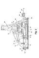
- FIG 2 is a cross-sectional view through line 2-2 of Figure 1 , showing additional details of the foot 14.
- the foot 14 can include a cleaning head 24 having a pivot joint 26 which couples the cleaning head 24 according to the invention to the lower handle assembly 18.
- the pivot joint 26 can be a universal joint with permits the foot 14 to swivel about multiple axes relative to the lower handle assembly 18.
- a cleaning cloth 28 through which steam and/or a cleaning fluid is dispensed onto a surface to be cleaned is coupled to a bottom of the cleaning head 24.
- the foot 14 can further comprise an agitator, such as a rotatably mounted brush, or an oscillating or otherwise movable cleaning cloth 28 for agitating and loosening foreign matter, such as dirt, dust and the like.
- the foot 14 can also include a sweeper assembly provided by a rotatably mounted brush and dirt collection bin for collecting dirt and dust.
- the cleaning cloth 28 can be removably coupled with the cleaning head 24 according to any known method. As illustrated, the cleaning cloth 28 is secured to the cleaning head 24 with a drawstring assembly 38 that tightens the cleaning cloth 28 around the cleaning head 24. In another example, the cleaning cloth 28 can be removably coupled with the cleaning head 24 using hook and loop fasteners, an example of which includes VELCRO®. In another example, one or more elastic straps can be used to secure the cleaning cloth 28 to the cleaning head 24. In yet another example, resilient cloth engagement and retention members having a plurality of outwardly radiating slits as is commonly known in the art can be used.
- a steam conduit 54 extends through the cleaning head 24 and couples at one end with a nozzle 52.
- the steam conduit 54 can include a first conduit portion 32 that extend through the pivot joint 26 and a second conduit portion 34, which may be in the form of a hose or flexible tubing that couples the first conduit portion to the nozzle 52.
- the nozzle 52 is positioned to direct steam or other cleaning fluid toward a steam manifold 36 that distributes the steam or other cleaning fluid over the cleaning cloth 28.
- FIG 3 illustrates a schematic of the fluid distribution system 30 which can be used with the steam mop 10 of Figure 1 for selectively generating and dispensing steam to a surface to be cleaned.
- the fluid distribution system 30 includes a fluid supply tank 40 for receiving and storing a cleaning fluid.
- the fluid supply tank 40 can be coupled with a pump 42 by a first fluid conduit 44.
- the pump 42 can be fluidly coupled with a heating element 48 for heating the fluid from the fluid supply tank 40 to generate steam through a second fluid conduit 50.
- the heating element 48 can comprise an elongated boiler having an inlet at one end that is fluidly coupled with the pump 42 and an outlet at an opposite end which is fluidly coupled with the nozzle 52 through the steam conduit 54.
- the fluid distribution system 30 is controlled by a microswitch 56, which is electrically connected to the pump 42.
- the steam mop 10 can also include a trigger 58 ( Figure 1 ) projecting outwardly from the grip assembly 22 for selective actuation by a user. Actuation of the trigger 58 actuates the microswitch 56 of the fluid distribution system 30 for selectively generating and dispensing steam.
- the microswitch 56 can also be electrically connected to the heating element 48 such that power is also supplied to the heating element 48.
- a separate actuator 60 shown in phantom line in Figure 3 , can be provided for activating the heating element 48.
- power can be supplied to the heating element continuously when the steam mop 10 is connected to a power source.
- Depressing the trigger 58 actuates the microswitch 56 and energizes the pump 42 to dispense fluid from the fluid tank 40 to the heating element 48 through the first and second fluid conduits 44 and 50 for selectively generating steam.
- the steam is delivered from the heating element 48 to the nozzle 52 through the steam conduit 54.
- the nozzle 52 can be mounted within the cleaning head 24 and configured to dispense steam onto the cleaning cloth 28.
- the fluid supply tank 40 can be configured to hold a predetermined amount of liquid.
- the liquid is water or electrolyzed water.
- An optional filter module (not shown) can be detachably connected to the fluid supply tank 40 for removing impurities within the cleaning fluid.
- the fluid supply tank 40 can be provided with a selectively closable opening through which a user can fill the fluid supply tank 40 with the desired liquid.
- FIG 4 illustrates one embodiment of the cleaning cloth 28 according to the invention.
- the cleaning cloth 28 includes the drawstring assembly 38, a bottom cloth 62, an edge cloth 64 attached to the bottom cloth 62.
- the drawstring assembly 38 includes a drawstring cord 66 and a cord lock 68 that attaches to the drawstring cord 66 to tighten the drawstring cord 66.
- the edge cloth 64 includes a channel 70 through which the drawstring cord 66 extends.
- the cleaning cloth 28 can be configured to be disposable after one or more uses, or can be washable for reuse.
- the bottom cloth 62 can be multi-layered, with at least one lower layer 72 and at least one upper layer 74.
- the layers 72, 74 can be made from a woven material, such as cotton, or a non-woven material, such as microfiber.
- At least the lower layer 72 can be textured to provide increased friction between the cleaning cloth 28 and the surface to be cleaned and loosen foreign matter, such as dirt, dust and the like. While the lower and upper layers 72, 74 may each be described herein as a single layer, each may instead include multiple layers of material attached together.
- the cleaning cloth 28 can also be provided with a cleaning component 76.
- the cleaning component 76 can include a disinfecting or sanitizing agent.
- the term "disinfecting or sanitizing agent” is used to refer to any organic or synthetic chemical or chemical composition having anti-bacterial, anti-viral, miticidal, germicidal, anti-fungal and anti-microbial properties.
- the cleaning component 76 can further or alternatively include a fragrance, an odor-eliminating agent, odor control agents (i.e.
- the cleaning cloth 28 can also include one or more floor care components, which may or may not be part of the cleaning component 76 to impart additional treatments to enhance the appearance and protection of the flooring surface, such as floor polish (i.e. Mop & Glo®), polymer protectant, anti-streaking components and vinegar, for example.
- floor polish i.e. Mop & Glo®
- the cleaning component 76 can be embedded within the bottom cloth 62, such as between the lower and upper layers 72, 74. Alternatively, the cleaning component can be affixed to the top surface of the bottom cloth 62 with dissolvable adhesive such as PVA tape, for example.
- the cleaning component 76 can be provided in different physical forms, such as in a singular form like a strip or wafer, a granulated form, a dissolvable or rupturable film sachet, or a gel contained within a heat- and/or moisture-soluble capsule. As illustrated in figure 4 , the cleaning component 76 is provided in strip form.
- the strip can be provided with one or more perforations or holes 82, which may increase the penetration of steam through the cleaning cloth 28 and/or increase the amount of surface area of the cleaning component 76 that is exposed to the steam.
- At least a portion of the upper layer 74 can form a cover 78 for a pocket that receives the cleaning component 76.
- the cover 78 can be provided with means that allow a user to easily open the cover 78, such hook and loop fasteners 80, an example of which includes VELCRO®. This would permit the user to replenish the cleaning component 76 as necessary. While shown as a flap being separable from the lower layer 72 on at least three sides, it is also possible for the cover 78 to only be separable from the lower layer 72 on one side, thereby permitting a user to slide the cleaning component 76 into the pocket between the lower and upper layers 72, 74.
- the cover 78 can be sealed around the cleaning component 76 to one of the layers 72, 74 after manufacture, for example when the cleaning cloth 28 is disposable cleaning.
- the cover 78 can be sealed using any suitable method, non-limited examples of which include stitching or adhesion.
- the cleaning component 76 can be embedded within or affixed to the bottom cloth 62 using any suitable method, a non-limiting example of which includes embedding the disinfecting or sanitizing formulation in water-soluble polymer film, which is then applied one or more layers 72, 74 of the bottom cloth 62.
- the film can be applied by various methods known in the art, such as, but not limited to, thermal bonding, ultrasonic bonding, adhesive bonding (including hot melt adhesive), and laminating.
- the encapsulated disinfecting or sanitizing formulation can be loosely placed between layers of the cleaning cloth 28. In this case, the layer(s) between the disinfecting or sanitizing formulation and the surface to be cleaned can be made from a moisture penetrative material.
- the cleaning component 76 can be inserted into the pocket between the lower and upper layers 72, 74, and the cover 78 thereafter closed over the cleaning component 76.
- the cleaning component 76 can be sprinkled onto the lower layer 72 or injected between the layers 72, 74.
- the cleaning component 76 can include an encapsulated formulation.
- the formulation can be encapsulated within an encapsulation barrier or capsule.
- the encapsulation barrier can be selected to rupture dissolve in the presence of moisture and/or heat.
- suitable encapsulation barriers include, but are not limited to, vinyl alcohol-vinyl acetate copolymer, polyvinyl alcohol polymer, and octenylsuccinates-starch polymer.
- the encapsulation barrier can comprise a polyvinyl alcohol (PVA) polymer film that is adapted to dissolve when exposed to moisture at or above a certain elevated threshold temperature, for example, 80°C or higher, such as the temperature required to generate steam. If the threshold temperature is not reached, the film barrier remains intact.
- PVA polyvinyl alcohol
- the encapsulated formulation can comprise one or more disinfecting or sanitizing agents. Encapsulation of the disinfecting or sanitizing formulation can prevent degradation of the disinfecting or sanitizing formulation and/or preserve the efficacy of the disinfecting or sanitizing formulation until the time of use. Encapsulation of the disinfecting or sanitizing formulation can also prevent premature reactions with other components embedded within the cleaning cloth 28. Exposure to moisture and/or heat will rupture or dissolve the encapsulation barrier, thereby releasing the disinfecting or sanitizing agents.
- Non-limiting examples of suitable disinfecting or sanitizing agents include quaternary ammonium compounds, also known as quats, such as Dialkyl quats, Dialkyl blend quats, single-chain quats and dual chain quats, hydrogen peroxide or hydrogen peroxide derivatives, or colloidal particles with disinfecting or sanitizing properties, like silver and/or copper.
- quats such as Dialkyl quats, Dialkyl blend quats, single-chain quats and dual chain quats, hydrogen peroxide or hydrogen peroxide derivatives, or colloidal particles with disinfecting or sanitizing properties, like silver and/or copper.
- the disinfecting or sanitizing formulation can be encapsulated according to any known method.
- One method of encapsulation includes adding lower molecular weight, waxy maize octenylsuccinates to starch polymer by esterifaction of starch hydroxyl groups with octenylsuccinic anhydride.
- Another method includes using polyvinyl alcohol to encapsulate the disinfecting or sanitizing formulation. This may be useful in the case of a strip- or wafer-form cleaning component 76.
- the encapsulated disinfecting or sanitizing formulation embedded in the cleaning cloth 28 can be one that has already been registered and approved by the U.S. Environmental Protection Agency (EPA). Examples of suitable EPA registered formulations are listed in the following table: Chemical Composition (Ingredient and Wt%) Trade Name Company EPA Number Alkyl dimethyl benzyl ammonium chloride (C 12- 18 ) 25% BTC® 2125M Stepan Company, Northfield, Illinois 1839-46 Alkyl Alkyl dimethyl benzyl ammonium chloride (C 12-14 ) 25% Inert ingredients 50% Alkyl dimethyl benzyl ammonium chloride (C 12- 18 ) 40% BTC® 2125M-80% Stepan Company, Northfield, Illinois 1839-54 Alkyl dimethyl benzyl ammonium chloride (C 12-14 ) 40% Inert ingredients 20% Alkyl dimethyl benzyl ammonium chloride (C 12-18 20% BTC® 2125M P40 Stepan Company, Northfield, Illinois 1839-55 Alkyl dimethyl
- the encapsulated formulation can comprise a fragrance, in addition to or alternatively to one or more disinfecting or sanitizing agents.
- the fragrance can be encapsulated within an encapsulation barrier or capsule selected to rupture or dissolve in the presence of moisture and heat. Encapsulation of the fragrance can prevent degradation of the fragrance and/or preserve the strength of the fragrance until the time of use. Exposure to moisture and/or heat will rupture or dissolve the encapsulation barrier, thereby releasing the fragrance.
- the fragrance can be encapsulated using any of the methods discussed herein.
- the moisture and heat from the steam distributed through the cleaning cloth 28 by the fluid dispensing system 30 interacts with the encapsulation barrier of the encapsulated formulation embedded within the cleaning cloth 28 to release the formulation onto the surface being cleaned.
- the moisture and steam can dissolve, melt or otherwise degrade the encapsulation barrier, thus releasing the formulation.
- only moisture or heat may be required to release the formulation.
- heat and moisture from the steam may be required to release the formulation.
- the cleaning cloth 28 shown in figure 4 includes an upper layer 74 forming a cover 78 in the form a flap, pouch or pocket for holding the cleaning component 76, the cover 78 can be omitted altogether and the cleaning component can be affixed directly to the top surface of the bottom cloth 62 as will be described hereinafter.
- Elements that are common or substantially similar to previously described elements of the invention are identified with the same reference numeral bearing a prime (') symbol.
- the cleaning component 90 can comprise a universal moisture and heat-soluble sachet 100 that is adapted for use with any cleaning cloth for a steam cleaner.
- the sachet 100 can comprise a top layer 102 and bottom layer 104 formed of moisture-soluble PVA film that is configured to dissolve over time upon exposure to at least one of moisture and heat.
- the top and bottom layers can be formed out of high temperature moisture-soluble PVA film configured to dissolve upon exposure to steam.
- the top and bottom layers 102, 104 are sealed around the perimeter of the sachet 100 forming a cavity 106 therebetween for receiving a variety of consumable materials, such as fragrance or a wide array of cleaning ingredients as previously described.
- the consumable materials can be provided in the form of a wafer insert 108 comprising anhydrous material such as powder, soap film or paper soap sheet encapsulated between the top and bottom layers 102, 104.
- the wafer insert 108 can be infused with one or more of a fragrance and a variety of cleaning compositions such as surfactants, oxygenated components, anti-streaking components, shine components or polymer protectant for example.
- materials such as fragrance can be provided in the form of anhydrous oil drops inserted between the top and bottom layers 102, 104 of the sachet 100.
- a moisture-soluble adhesive 110 such as PVA tape
- the adhesive 110 can include a user-removable liner (not shown) that a user can remove to expose the adhesive tape prior to affixing the sachet to the top surface of the bottom cloth 62.
- the sachet 100 can be positioned on the bottom cloth 62 so that it is exposed to the steam distributor nozzle 52 when the cleaning cloth 28 is mounted to the foot 14. Accordingly, the cleaning component 90 can be easily affixed to any cleaning cloth for a steam cleaner.
- the sachet 100 can be inserted into a pouch, pocket, or separable flap formed on the top of the bottom cloth as previously described.
- steam flows through the distributor nozzle 52 and contacts the cleaning component 90.
- the steam dissolves the top and bottom layers 102, 104 of the sachet 100 as well as the adhesive 110 and eventually exposes the wafer insert 108 therein.
- the wafer insert 108 and material infused therein are dissolved into the cleaning cloth 28 and as the cloth becomes saturated with steam, the ingredients of the cleaning component 90 are distributed onto the surface to be cleaned or into the ambient atmosphere. Because the top and bottom layers 102, 104 and adhesive 110 are all configured to dissolve over time upon exposure to steam, a user does not have to contact the soiled cleaning cloth 28 to remove and dispose the cleaning component 90 prior to laundering the cleaning cloth 28.
- the cleaning component 190 can comprise a wafer 200 that is formed of fragrance-infused thermoplastic concentrate such as polyethelyne (PE), polypropylene (PP), or polyvinyl chloride (PVC). Elements that are common or substantially similar to previously described elements of the invention are identified with the same reference numeral bearing a double prime (") symbol.
- the wafer 200 can comprise a variety of shapes and sizes. In one embodiment the wafer 200 can comprise a thin, flexible injection-molded rectangular card akin to a conventional credit card. The wafer 200 can be inserted into a pouch 202, pocket, or separable flap formed on the top of the bottom cloth 62" as previously described. Alternatively, the wafer 200 can be removably coupled to either of the cleaning cloth 28" or cleaning head 24 by any suitable attachment means such as hook and loop fasteners, or a temporary or removable adhesive, for example.
- any suitable attachment means such as hook and loop fasteners, or a temporary or removable adhesive, for example.
- infused fragrance can be configured to last for one or more cleaning operations, but will eventually diminish to a negligible level.
- the user can replace the spent wafer with a fresh wafer to renew emission of the consumable during use.
- a wafer 300 can comprise a porous film 306 formed of thermoplastic sheet material of polyethylene (PE), polypropylene (PP) or polyvinylidene fluoride (PVDF), for example.
- a plurality of pores 302 are dispersed throughout the film 306. Pore sizes can range from approximately 10 to 150 microns.
- the wafer 300 can further comprise a coating 304 such as a liquid or gel fragrance, which saturates the pores.
- the coating 304 can optionally further comprise a variety of additional cleaning ingredients as previously described.
- the wafer 300 can comprise a useful life indicator.
- the fragrance can comprise a color tint that contrasts with the wafer substrate material, which can be white or transparent. Fragrance dissipates during use and thus exposes an increasing area of the color contrasting wafer substrate, thereby indicating the remaining useful life of the wafer.
- the coating can be configured to have a useful life of one or more cleaning tasks, but will eventually diminish to a negligible level.
- the coating can comprise a fragrance that gradually diminishes during use.
- the fragrance can be color-tinted so that it progressively fades and exposes an increasing area of the color contrasting wafer substrate, until the color dissipates completely and the entire wafer film 306 is exposed. Accordingly, the wafer 200, 300 and color-tinted fragrance coating are adapted to provide an end of useful life indicator that signals a user to replace the wafer with a fresh, unused wafer.
Landscapes
- Chemical & Material Sciences (AREA)
- Life Sciences & Earth Sciences (AREA)
- Organic Chemistry (AREA)
- Chemical Kinetics & Catalysis (AREA)
- Oil, Petroleum & Natural Gas (AREA)
- Wood Science & Technology (AREA)
- Engineering & Computer Science (AREA)
- Health & Medical Sciences (AREA)
- Epidemiology (AREA)
- Animal Behavior & Ethology (AREA)
- General Health & Medical Sciences (AREA)
- Public Health (AREA)
- Veterinary Medicine (AREA)
- Cleaning Implements For Floors, Carpets, Furniture, Walls, And The Like (AREA)
Abstract
Description
- Steam mops are well known devices for cleaning bare floor surfaces, such as tile, linoleum, vinyl, laminate, and hardwood floors. Typical steam mops have a reservoir for storing water that is fluidly connected to a selectively engageable pump or valve. The pump or valve outlet is fluidly connected to a steam boiler with a heating element to heat the water. The steam boiler generates steam, which is directed towards the cleaning surface through a nozzle or manifold mounted in the foot. Steam is typically applied to the backside of a mop pad or cloth attached to the foot. Steam vapor eventually saturates the entire pad as the moisture wicks outwardly from the point of steam application. The damp pad is wiped across the surface to be cleaned to remove dirt, dust, and debris present on the cleaning surface.
- A bare floor cleaner has heretofore been sold in the United States by BISSELL Homecare, Inc. under the mark Steam Mop™. The Steam Mop™ bare floor cleaner comprises a base assembly and an upright handle pivotally mounted to the base assembly. The base assembly includes a base housing with a fluid distributor for distributing fluid to the surface to be cleaned and a mop pad that is affixed beneath the base housing and positioned for contacting the surface to be cleaned. The upright handle includes a handle housing, a water tank mounted to the handle housing and adapted to hold a quantity of water, a fluid distribution system between the water tank and the base housing fluid distributor for distributing fluid from the water tank to the mop pad for applying the steam to the surface to be cleaned, and a heating element within the fluid distribution system for heating the water from the water tank to steam.
- During use, the mop pad eventually becomes saturated with liquid and soiled with embedded dirt, dust, and debris. The soiled mop pad can be laundered and re-used. A mop pad can generally be used for one or two steam mopping sessions prior to being laundered.
- According to the invention, a cleaning cloth for use with a steam mop has at least one fabric layer that is configured to be attached to a steam mop and an encapsulated cleaning composition associated with the fabric layer and configured to be released by exposure to steam delivered to the cleaning cloth. The steam mop may have a housing mounting the cleaning cloth for cleaning the surface to be cleaned and a steam delivery system for delivering steam to the cleaning cloth.
- In one embodiment, the at least one fabric layer comprises two fabric layers that form a pocket and the encapsulated cleaning composition is positioned in the pocket. The at least one fabric layer can further comprises a cover for closing an opening to the pocket. The at least one fabric layer can comprises a lower fabric layer and an upper fabric layer, and the encapsulated cleaning composition can be positioned between the upper and lower fabric layers. Further, the lower fabric layer can be textured to increase friction with the surface to be cleaned. Further, the upper fabric layer can be joined with the lower fabric layer at one edge to form a flap that is separable from the lower layer. The flap and lower fabric can include a hook and loop fastener combination between two.
- In another embodiment, the encapsulated cleaning composition is embedded within or attached to the at least one fabric layer. In addition, the encapsulated cleaning composition can include a cleaning composition embedded within a water-soluble polymer film, which is mounted to the at least one fabric layer. The film can be mounted by one of thermal bonding, ultrasonic bonding, adhesive bonding, including hot melt adhesive and dissolvable adhesive, and laminating.
- The encapsulated cleaning composition can comprise a disinfecting or sanitizing agent having anti-bacterial, anti-viral, miticidal, germicidal, anti-fungal or anti-microbial properties. In addition, the disinfecting or sanitizing agent can comprise an EPA-exempted natural disinfectant. In addition, the disinfecting or sanitizing agent can comprise one of: quaternary ammonium compounds (quats), such as Dialkyl quats, Dialkyl blend quats, single-chain quats and dual chain quats, hydrogen peroxide or hydrogen peroxide derivatives, or colloidal particles with disinfecting or sanitizing properties, including silver and/or copper. In addition, the encapsulated cleaning composition can comprise at least one of a fragrance, an odor-eliminating agent, and an odor control agent. In addition, the encapsulated cleaning composition can comprise at least one floor care component, including floor polish, polymer protectant, anti-streaking components, or vinegar.
- In another embodiment, the encapsulated cleaning composition is bonded, affixed or in register with the at least one fabric layer. In addition, the encapsulated cleaning composition can be embodied in at least one of a film, a wafer, a pouch, a sachet, and a granulated composition.
- In addition, the wafer can be a fragrance-infused thermoplastic sheet and the fragrance can be volatilized into the cleaning cloth and surrounding atmosphere when the at least one fabric layer is exposed to steam. In addition, the wafer can comprise multiple perforations to pass steam through the cleaning composition. In addition, the wafer can be a porous plastic sheet and the cleaning composition can be released from the perforations into the cleaning cloth and surrounding atmosphere when the wafer is exposed to steam.
- In an alternative embodiment, the encapsulated composition comprises a gel contained within a heat- and/or moisture-soluble barrier.
- Alternatively, the barrier comprises one of vinyl alcohol-vinyl acetate copolymer, polyvinyl alcohol polymer, and octenylsuccinates-starch polymer.
- In a preferred embodiment, the encapsulated cleaning composition is released only upon reaching a temperature of at least about 80°C.
- Further according to the invention, a steam mop comprises a housing for movement along a surface to be cleaned, a cleaning cloth as described above is coupled with the housing for cleaning the surface to be cleaned, and a steam delivery system for delivering steam to the cleaning cloth. In one embodiment, the housing comprises a foot assembly for movement along a surface to be cleaned and a handle assembly mounted to the foot assembly. The cleaning cloth can be mounted to the foot assembly.
- Further according to the invention, a method for cleaning a surface comprises applying to the surface a cleaning cloth with a cleaning composition encapsulated within a heat-activated barrier and delivering steam to the cleaning cloth to release the cleaning composition onto the surface.
- In the drawings:
-
Figure 1 is a front perspective view of an upright steam mop according to an embodiment of the invention. -
Figure 2 is a cross-sectional view through line 2-2 ofFigure 1 . -
Figure 3 is a schematic of a fluid distribution system of the upright steam mop ofFigure 1 . -
Figure 4 is a perspective view of a cleaning cloth for use with the upright steam mop ofFigure 1 . -
Figure 5 is a perspective view of a universal cleaning component according to another embodiment of the invention. -
Figure 6 is a cross-sectional view of the cleaning cloth ofFigure 5 taken along line 6-6 ofFigure 5 . -
Figure 7 is an exploded, perspective view of a cleaning component and cleaning cloth according to another embodiment of the invention. -
Figure 8 is a cross-sectional view of a cleaning component according to another embodiment of the invention. - The invention relates to a cleaning cloth that can be removably mounted to an otherwise conventional steam mop as illustrated in
Figure 1 . Asteam mop 10 described herein can share many features of a traditional steam mop, which will not be described in detail except as necessary for a complete understanding of the invention. Examples of suitable steam mops which may be used with the embodiments of the invention described herein include the Steam Mop™, sold in the United States by BISSELL Homecare, Inc. and International Application No.PCT/US10/45167, filed August 11, 2010 , titled "Upright Steam Mop with Auxiliary Hand Tool" andU.S. Application No. 12/778,615, filed May 12, 2010 - The
steam mop 10 can comprise anupright handle assembly 12 and a base orfoot 14 pivotally mounted to thehandle assembly 12. Thehandle assembly 12 can pivot from an upright or vertical position, where thehandle assembly 12 is substantially vertical relative to a surface to be cleaned, to a lowered position, whereby thehandle assembly 12 is rotated in a rearward direction relative to thefoot 14 to an acute angled relative to the surface to be cleaned. Thesteam mop 10 is adapted to glide across the floor or other hard surface on thefoot 14. - The
handle assembly 12 comprises anupper handle assembly 16 and alower handle assembly 18. Theupper handle assembly 16 comprises ahollow handle tube 20 having agrip assembly 22 fixedly attached to a first end of thehandle tube 20 and thelower handle assembly 18 fixedly attached to a second end of thehandle tube 20 via screws or other suitable commonly known fasteners. Thegrip assembly 22 has an arcuate grip portion; however, it is within the scope of the invention to utilize other grips commonly found on other machines, such as closed-loop grips having circular or triangular shapes. - The
lower handle assembly 18 and/or thefoot 14 can further include afluid distribution system 30. Thefluid distribution system 30 can be primarily located within thelower handle assembly 18, although it is also within the scope of the invention for all or a portion of thefluid distribution system 30 to be located within thefoot 14. -
Figure 2 is a cross-sectional view through line 2-2 ofFigure 1 , showing additional details of thefoot 14. Thefoot 14 can include a cleaninghead 24 having a pivot joint 26 which couples the cleaninghead 24 according to the invention to thelower handle assembly 18. The pivot joint 26 can be a universal joint with permits thefoot 14 to swivel about multiple axes relative to thelower handle assembly 18. A cleaningcloth 28 through which steam and/or a cleaning fluid is dispensed onto a surface to be cleaned is coupled to a bottom of the cleaninghead 24. It is also contemplated that thefoot 14 can further comprise an agitator, such as a rotatably mounted brush, or an oscillating or otherwisemovable cleaning cloth 28 for agitating and loosening foreign matter, such as dirt, dust and the like. Alternatively, thefoot 14 can also include a sweeper assembly provided by a rotatably mounted brush and dirt collection bin for collecting dirt and dust. - The cleaning
cloth 28 can be removably coupled with the cleaninghead 24 according to any known method. As illustrated, the cleaningcloth 28 is secured to the cleaninghead 24 with adrawstring assembly 38 that tightens the cleaningcloth 28 around the cleaninghead 24. In another example, the cleaningcloth 28 can be removably coupled with the cleaninghead 24 using hook and loop fasteners, an example of which includes VELCRO®. In another example, one or more elastic straps can be used to secure the cleaningcloth 28 to the cleaninghead 24. In yet another example, resilient cloth engagement and retention members having a plurality of outwardly radiating slits as is commonly known in the art can be used. - A
steam conduit 54 extends through the cleaninghead 24 and couples at one end with anozzle 52. Thesteam conduit 54 can include afirst conduit portion 32 that extend through the pivot joint 26 and asecond conduit portion 34, which may be in the form of a hose or flexible tubing that couples the first conduit portion to thenozzle 52. Thenozzle 52 is positioned to direct steam or other cleaning fluid toward asteam manifold 36 that distributes the steam or other cleaning fluid over the cleaningcloth 28. -
Figure 3 illustrates a schematic of thefluid distribution system 30 which can be used with thesteam mop 10 ofFigure 1 for selectively generating and dispensing steam to a surface to be cleaned. Thefluid distribution system 30 includes afluid supply tank 40 for receiving and storing a cleaning fluid. Thefluid supply tank 40 can be coupled with apump 42 by a firstfluid conduit 44. Thepump 42 can be fluidly coupled with aheating element 48 for heating the fluid from thefluid supply tank 40 to generate steam through a secondfluid conduit 50. Theheating element 48 can comprise an elongated boiler having an inlet at one end that is fluidly coupled with thepump 42 and an outlet at an opposite end which is fluidly coupled with thenozzle 52 through thesteam conduit 54. - The
fluid distribution system 30 is controlled by amicroswitch 56, which is electrically connected to thepump 42. Thesteam mop 10 can also include a trigger 58 (Figure 1 ) projecting outwardly from thegrip assembly 22 for selective actuation by a user. Actuation of thetrigger 58 actuates themicroswitch 56 of thefluid distribution system 30 for selectively generating and dispensing steam. Themicroswitch 56 can also be electrically connected to theheating element 48 such that power is also supplied to theheating element 48. Alternatively, aseparate actuator 60, shown in phantom line inFigure 3 , can be provided for activating theheating element 48. In yet another configuration, power can be supplied to the heating element continuously when thesteam mop 10 is connected to a power source. Depressing thetrigger 58 actuates themicroswitch 56 and energizes thepump 42 to dispense fluid from thefluid tank 40 to theheating element 48 through the first and secondfluid conduits heating element 48 to thenozzle 52 through thesteam conduit 54. Thenozzle 52 can be mounted within the cleaninghead 24 and configured to dispense steam onto the cleaningcloth 28. - The
fluid supply tank 40 can be configured to hold a predetermined amount of liquid. In one embodiment, the liquid is water or electrolyzed water. Optionally, a variety of cleaning chemicals, fragrances, botanical oils, and the like can be mixed with the water. An optional filter module (not shown) can be detachably connected to thefluid supply tank 40 for removing impurities within the cleaning fluid. Thefluid supply tank 40 can be provided with a selectively closable opening through which a user can fill thefluid supply tank 40 with the desired liquid. -
Figure 4 illustrates one embodiment of the cleaningcloth 28 according to the invention. The cleaningcloth 28 includes thedrawstring assembly 38, abottom cloth 62, anedge cloth 64 attached to thebottom cloth 62. Thedrawstring assembly 38 includes adrawstring cord 66 and acord lock 68 that attaches to thedrawstring cord 66 to tighten thedrawstring cord 66. Theedge cloth 64 includes achannel 70 through which thedrawstring cord 66 extends. The cleaningcloth 28 can be configured to be disposable after one or more uses, or can be washable for reuse. - The
bottom cloth 62 can be multi-layered, with at least onelower layer 72 and at least oneupper layer 74. Thelayers lower layer 72 can be textured to provide increased friction between the cleaningcloth 28 and the surface to be cleaned and loosen foreign matter, such as dirt, dust and the like. While the lower andupper layers - The cleaning
cloth 28 can also be provided with acleaning component 76. Thecleaning component 76 can include a disinfecting or sanitizing agent. As used herein, the term "disinfecting or sanitizing agent" is used to refer to any organic or synthetic chemical or chemical composition having anti-bacterial, anti-viral, miticidal, germicidal, anti-fungal and anti-microbial properties. Thecleaning component 76 can further or alternatively include a fragrance, an odor-eliminating agent, odor control agents (i.e. Febreze®), and EPA-exempted natural disinfectants, including botanical disinfectants comprising one or more essential oils such as thyme, peppermint, eucalyptus, cinnamon, lemongrass, thyme or other natural oils. The cleaningcloth 28 can also include one or more floor care components, which may or may not be part of thecleaning component 76 to impart additional treatments to enhance the appearance and protection of the flooring surface, such as floor polish (i.e. Mop & Glo®), polymer protectant, anti-streaking components and vinegar, for example. - The
cleaning component 76 can be embedded within thebottom cloth 62, such as between the lower andupper layers bottom cloth 62 with dissolvable adhesive such as PVA tape, for example. Thecleaning component 76 can be provided in different physical forms, such as in a singular form like a strip or wafer, a granulated form, a dissolvable or rupturable film sachet, or a gel contained within a heat- and/or moisture-soluble capsule. As illustrated infigure 4 , thecleaning component 76 is provided in strip form. The strip can be provided with one or more perforations or holes 82, which may increase the penetration of steam through the cleaningcloth 28 and/or increase the amount of surface area of thecleaning component 76 that is exposed to the steam. - At least a portion of the
upper layer 74 can form acover 78 for a pocket that receives thecleaning component 76. As illustrated, thecover 78 can be provided with means that allow a user to easily open thecover 78, such hook andloop fasteners 80, an example of which includes VELCRO®. This would permit the user to replenish thecleaning component 76 as necessary. While shown as a flap being separable from thelower layer 72 on at least three sides, it is also possible for thecover 78 to only be separable from thelower layer 72 on one side, thereby permitting a user to slide thecleaning component 76 into the pocket between the lower andupper layers cover 78 can be sealed around thecleaning component 76 to one of thelayers cloth 28 is disposable cleaning. Thecover 78 can be sealed using any suitable method, non-limited examples of which include stitching or adhesion. - The
cleaning component 76 can be embedded within or affixed to thebottom cloth 62 using any suitable method, a non-limiting example of which includes embedding the disinfecting or sanitizing formulation in water-soluble polymer film, which is then applied one ormore layers bottom cloth 62. The film can be applied by various methods known in the art, such as, but not limited to, thermal bonding, ultrasonic bonding, adhesive bonding (including hot melt adhesive), and laminating. Alternatively, the encapsulated disinfecting or sanitizing formulation can be loosely placed between layers of the cleaningcloth 28. In this case, the layer(s) between the disinfecting or sanitizing formulation and the surface to be cleaned can be made from a moisture penetrative material. In the case of a strip or wafer-form cleaning component 76, thecleaning component 76 can be inserted into the pocket between the lower andupper layers cover 78 thereafter closed over thecleaning component 76. In the case of agranulated cleaning component 76, thecleaning component 76 can be sprinkled onto thelower layer 72 or injected between thelayers - The
cleaning component 76 can include an encapsulated formulation. The formulation can be encapsulated within an encapsulation barrier or capsule. The encapsulation barrier can be selected to rupture dissolve in the presence of moisture and/or heat. Some examples of suitable encapsulation barriers include, but are not limited to, vinyl alcohol-vinyl acetate copolymer, polyvinyl alcohol polymer, and octenylsuccinates-starch polymer. In one embodiment, the encapsulation barrier can comprise a polyvinyl alcohol (PVA) polymer film that is adapted to dissolve when exposed to moisture at or above a certain elevated threshold temperature, for example, 80°C or higher, such as the temperature required to generate steam. If the threshold temperature is not reached, the film barrier remains intact. - The encapsulated formulation can comprise one or more disinfecting or sanitizing agents. Encapsulation of the disinfecting or sanitizing formulation can prevent degradation of the disinfecting or sanitizing formulation and/or preserve the efficacy of the disinfecting or sanitizing formulation until the time of use. Encapsulation of the disinfecting or sanitizing formulation can also prevent premature reactions with other components embedded within the cleaning
cloth 28. Exposure to moisture and/or heat will rupture or dissolve the encapsulation barrier, thereby releasing the disinfecting or sanitizing agents. - Non-limiting examples of suitable disinfecting or sanitizing agents include quaternary ammonium compounds, also known as quats, such as Dialkyl quats, Dialkyl blend quats, single-chain quats and dual chain quats, hydrogen peroxide or hydrogen peroxide derivatives, or colloidal particles with disinfecting or sanitizing properties, like silver and/or copper.
- The disinfecting or sanitizing formulation can be encapsulated according to any known method. One method of encapsulation includes adding lower molecular weight, waxy maize octenylsuccinates to starch polymer by esterifaction of starch hydroxyl groups with octenylsuccinic anhydride. Another method includes using polyvinyl alcohol to encapsulate the disinfecting or sanitizing formulation. This may be useful in the case of a strip- or wafer-
form cleaning component 76. - The encapsulated disinfecting or sanitizing formulation embedded in the cleaning
cloth 28 can be one that has already been registered and approved by the U.S. Environmental Protection Agency (EPA). Examples of suitable EPA registered formulations are listed in the following table:Chemical Composition (Ingredient and Wt%) Trade Name Company EPA Number Alkyl dimethyl benzyl ammonium chloride (C12- 18) 25% BTC® 2125M Stepan Company, Northfield, Illinois 1839-46 Alkyl Alkyl dimethyl benzyl ammonium chloride (C12-14) 25% Inert ingredients 50% Alkyl dimethyl benzyl ammonium chloride (C12- 18) 40% BTC® 2125M-80% Stepan Company, Northfield, Illinois 1839-54 Alkyl dimethyl benzyl ammonium chloride (C12-14) 40% Inert ingredients 20% Alkyl dimethyl benzyl ammonium chloride (C12-18 20% BTC® 2125M P40 Stepan Company, Northfield, Illinois 1839-55 Alkyl dimethyl benzyl ammonium chloride (C12-14) 20% Inert ingredients 60% Alkyl dimethyl benzyl ammonium chloride (C12-18 ) 25% Maquat MQ2525M-50% Mason Chemical Co., Arlington Heights, Illinois 10324-28 Alkyl dimethyl ethyl benzyl ammonium chloride (C12-14) 25% Ethanol 2% Water 48% Alkyl dimethyl benzyl ammonium chloride (C12-18 ) 40% Maquat MQ2525M-80% Mason Chemical Co., Arlington Heights, Illinois 10324-27 Alkyl dimethyl ethyl benzyl ammonium chloride (C12-14) 40% Ethanol 10% Water 10% Alkyl dimethyl benzyl ammonium chloride (C12- 16) 20% Maquat MQ615M Mason Chemical Co., Arlington Heights, Illinois 10324-51 Octyl decyl dimethyl ammonium chloride 15% Dioctyl dimethyl ammonium chloride 7.5% Didecyl dimethyl ammonium chloride 7.5% Ethanol 5-10% Water 40-45% Didecyl dimethyl ammonium chloride 50% Maquat 4450-E Mason Chemical Co., Arlington Heights, Illinois 10324-34 Ethanol 10% Water 40% Alkyl (C14 50%, C16 10%, C12 40%) Dimethyl Benzyl Ammonium Chloride 50% Barquat® MB-50 Lonza, Basel, Switzerland 6836-2 Ethyl alcohol 10% Water 40% Alkyl (C14 50%, C16 10%, C12 40%) Dimethyl Benzyl Ammonium Chloride 80% Barquat® MB-80 Lonza, Basel, Switzerland 6836-14 Ethyl alcohol 10% Water 10% - The encapsulated formulation can comprise a fragrance, in addition to or alternatively to one or more disinfecting or sanitizing agents. The fragrance can be encapsulated within an encapsulation barrier or capsule selected to rupture or dissolve in the presence of moisture and heat. Encapsulation of the fragrance can prevent degradation of the fragrance and/or preserve the strength of the fragrance until the time of use. Exposure to moisture and/or heat will rupture or dissolve the encapsulation barrier, thereby releasing the fragrance. The fragrance can be encapsulated using any of the methods discussed herein.
- In use, the moisture and heat from the steam distributed through the cleaning
cloth 28 by thefluid dispensing system 30 interacts with the encapsulation barrier of the encapsulated formulation embedded within the cleaningcloth 28 to release the formulation onto the surface being cleaned. The moisture and steam can dissolve, melt or otherwise degrade the encapsulation barrier, thus releasing the formulation. Depending on the encapsulation barrier, only moisture or heat may be required to release the formulation. Alternatively, heat and moisture from the steam may be required to release the formulation. Although the cleaningcloth 28 shown infigure 4 includes anupper layer 74 forming acover 78 in the form a flap, pouch or pocket for holding thecleaning component 76, thecover 78 can be omitted altogether and the cleaning component can be affixed directly to the top surface of thebottom cloth 62 as will be described hereinafter. Elements that are common or substantially similar to previously described elements of the invention are identified with the same reference numeral bearing a prime (') symbol. - As depicted in
Figures 5-6 , thecleaning component 90 can comprise a universal moisture and heat-soluble sachet 100 that is adapted for use with any cleaning cloth for a steam cleaner. Thesachet 100 can comprise atop layer 102 andbottom layer 104 formed of moisture-soluble PVA film that is configured to dissolve over time upon exposure to at least one of moisture and heat. Alternatively, the top and bottom layers can be formed out of high temperature moisture-soluble PVA film configured to dissolve upon exposure to steam. The top andbottom layers sachet 100 forming acavity 106 therebetween for receiving a variety of consumable materials, such as fragrance or a wide array of cleaning ingredients as previously described. The consumable materials can be provided in the form of awafer insert 108 comprising anhydrous material such as powder, soap film or paper soap sheet encapsulated between the top andbottom layers wafer insert 108 can be infused with one or more of a fragrance and a variety of cleaning compositions such as surfactants, oxygenated components, anti-streaking components, shine components or polymer protectant for example. Alternatively, materials such as fragrance can be provided in the form of anhydrous oil drops inserted between the top andbottom layers sachet 100. - As shown in
Figures 5-6 , a moisture-soluble adhesive 110, such as PVA tape, can be secured to the bottom surface of thesachet 100. The adhesive 110 can include a user-removable liner (not shown) that a user can remove to expose the adhesive tape prior to affixing the sachet to the top surface of thebottom cloth 62. Thesachet 100 can be positioned on thebottom cloth 62 so that it is exposed to thesteam distributor nozzle 52 when the cleaningcloth 28 is mounted to thefoot 14. Accordingly, thecleaning component 90 can be easily affixed to any cleaning cloth for a steam cleaner. Alternatively, thesachet 100 can be inserted into a pouch, pocket, or separable flap formed on the top of the bottom cloth as previously described. - In operation, steam flows through the
distributor nozzle 52 and contacts thecleaning component 90. The steam dissolves the top andbottom layers sachet 100 as well as the adhesive 110 and eventually exposes thewafer insert 108 therein. Thewafer insert 108 and material infused therein are dissolved into the cleaningcloth 28 and as the cloth becomes saturated with steam, the ingredients of thecleaning component 90 are distributed onto the surface to be cleaned or into the ambient atmosphere. Because the top andbottom layers soiled cleaning cloth 28 to remove and dispose thecleaning component 90 prior to laundering the cleaningcloth 28. - In another embodiment of the invention shown in
Figures 7 , the cleaning component 190 can comprise a wafer 200 that is formed of fragrance-infused thermoplastic concentrate such as polyethelyne (PE), polypropylene (PP), or polyvinyl chloride (PVC). Elements that are common or substantially similar to previously described elements of the invention are identified with the same reference numeral bearing a double prime (") symbol. The wafer 200 can comprise a variety of shapes and sizes. In one embodiment the wafer 200 can comprise a thin, flexible injection-molded rectangular card akin to a conventional credit card. The wafer 200 can be inserted into apouch 202, pocket, or separable flap formed on the top of thebottom cloth 62" as previously described. Alternatively, the wafer 200 can be removably coupled to either of the cleaningcloth 28" or cleaninghead 24 by any suitable attachment means such as hook and loop fasteners, or a temporary or removable adhesive, for example. - In operation, steam flows through the
distributor nozzle 52 and contacts the wafer 200. Heat and moisture from the steam accelerates the release and volatilization of the infused fragrance from the wafer 200 into the cleaningcloth 28" and surrounding atmosphere. The infused fragrance can be configured to last for one or more cleaning operations, but will eventually diminish to a negligible level. The user can replace the spent wafer with a fresh wafer to renew emission of the consumable during use. - In yet another embodiment illustrated in
Fig. 8 , awafer 300 can comprise aporous film 306 formed of thermoplastic sheet material of polyethylene (PE), polypropylene (PP) or polyvinylidene fluoride (PVDF), for example. A plurality ofpores 302 are dispersed throughout thefilm 306. Pore sizes can range from approximately 10 to 150 microns. Thewafer 300 can further comprise acoating 304 such as a liquid or gel fragrance, which saturates the pores. Thecoating 304 can optionally further comprise a variety of additional cleaning ingredients as previously described. Optionally, thewafer 300 can comprise a useful life indicator. For example, the fragrance can comprise a color tint that contrasts with the wafer substrate material, which can be white or transparent. Fragrance dissipates during use and thus exposes an increasing area of the color contrasting wafer substrate, thereby indicating the remaining useful life of the wafer. - In operation, steam flows through the
steam distributor nozzle 52 and contacts thewafer 300. Heat or a combination of heat and moisture from the steam volatilizes thecoating 304 and releases it from thepores 302 and surface of thefilm 300 into the cleaning cloth and surrounding atmosphere. The coating can be configured to have a useful life of one or more cleaning tasks, but will eventually diminish to a negligible level. For example, the coating can comprise a fragrance that gradually diminishes during use. The fragrance can be color-tinted so that it progressively fades and exposes an increasing area of the color contrasting wafer substrate, until the color dissipates completely and theentire wafer film 306 is exposed. Accordingly, thewafer 200, 300 and color-tinted fragrance coating are adapted to provide an end of useful life indicator that signals a user to replace the wafer with a fresh, unused wafer. - While the invention has been specifically described in connection with certain specific embodiments thereof, it is to be understood that this is by way of illustration and not of limitation, and the scope of the appended claims should be construed as broadly as the prior art will permit. Reasonable variation and modification are possible within the foregoing specification and drawings without departing from the spirit of the invention, which is set forth in the accompanying claims.
Claims (15)
- A cleaning cloth for use with a steam mop having a housing mounting the cleaning cloth for cleaning the surface to be cleaned and a steam delivery system for delivering steam to the cleaning cloth, the cleaning cloth comprising:at least one fabric layer that is configured to be attached to a steam mop; andan encapsulated cleaning composition associated with the fabric layer and configured to be released by exposure to steam delivered to the cleaning cloth.
- A cleaning cloth according to claim 1 wherein the at least one fabric layer comprises two fabric layers that form a pocket and the encapsulated cleaning composition is positioned in the pocket.
- A cleaning cloth according to claim 1 wherein the encapsulated cleaning composition is embedded within or attached to the at least one fabric layer.
- A cleaning cloth according to claim 1 wherein the encapsulated cleaning composition is embedded within a water-soluble polymer film or a gel, which is mounted to the at least one fabric layer.
- A cleaning cloth according to claim 1 wherein the encapsulated cleaning composition comprises a disinfecting or sanitizing agent having anti-bacterial, anti-viral, miticidal, germicidal, anti-fungal or anti-microbial properties.
- A cleaning cloth according to claim 5 wherein the disinfecting or sanitizing agent comprises one of: quaternary ammonium compounds (quats), such as Dialkyl quats, Dialkyl blend quats, single-chain quats and dual chain quats, hydrogen peroxide or hydrogen peroxide derivatives, or colloidal particles with disinfecting or sanitizing properties, including silver and/or copper.
- A cleaning cloth according to claim 1 wherein the encapsulated cleaning composition comprises at least one of a fragrance, an odor-eliminating agent, and an odor control agent.
- A cleaning cloth according to any of claims 1-7 wherein the encapsulated cleaning composition further comprises at least one floor care component, including floor polish, polymer protectant, anti-streaking components, or vinegar.
- A cleaning cloth according to claim 1 wherein the encapsulated cleaning composition is embodied in at least one of a film, a wafer, a pouch, a sachet, and a granulated composition.
- A cleaning cloth according to claim 1 wherein the encapsulated cleaning composition comprises a wafer, and the wafer comprises a fragrance-infused thermoplastic sheet and the fragrance is volatilized into the cleaning cloth and surrounding atmosphere when the sheet is exposed to steam.
- A cleaning cloth according to claim 1 wherein the encapsulated cleaning composition comprises a wafer, and the wafer is a porous plastic sheet and the cleaning composition is released from the perforations into the cleaning cloth and surrounding atmosphere when the wafer is exposed to steam.
- A cleaning cloth according to claim 1 wherein the encapsulated composition comprises a gel contained within a heat- and/or moisture-soluble barrier.
- A cleaning cloth according to claim 12 wherein the barrier comprises one of vinyl alcohol-vinyl acetate copolymer, polyvinyl alcohol polymer, and octenylsuccinates-starch polymer.
- A cleaning cloth according to claim 1 wherein the encapsulated cleaning composition is released only upon reaching a temperature of at least about 80°C.
- A method for cleaning a surface comprising:applying to the surface a cleaning cloth with a cleaning composition encapsulated within a heat-activated barrier; anddelivering steam to the cleaning cloth to release the cleaning composition onto the surface.
Applications Claiming Priority (1)
| Application Number | Priority Date | Filing Date | Title |
|---|---|---|---|
| US42276510P | 2010-12-14 | 2010-12-14 |
Publications (3)
| Publication Number | Publication Date |
|---|---|
| EP2465400A2 true EP2465400A2 (en) | 2012-06-20 |
| EP2465400A3 EP2465400A3 (en) | 2014-07-02 |
| EP2465400B1 EP2465400B1 (en) | 2016-03-09 |
Family
ID=45350675
Family Applications (1)
| Application Number | Title | Priority Date | Filing Date |
|---|---|---|---|
| EP11193386.7A Active EP2465400B1 (en) | 2010-12-14 | 2011-12-14 | Cleaning cloth with encapsulated formulation, steam mop and method |
Country Status (4)
| Country | Link |
|---|---|
| US (1) | US8927480B2 (en) |
| EP (1) | EP2465400B1 (en) |
| CN (1) | CN102525352B (en) |
| AU (1) | AU2011254005B2 (en) |
Cited By (4)
| Publication number | Priority date | Publication date | Assignee | Title |
|---|---|---|---|---|
| WO2014152464A1 (en) * | 2013-03-15 | 2014-09-25 | Scolari Nathan Anthony | Improved steamer mop having quick change cleaning pad |
| EP2801314A1 (en) * | 2013-05-10 | 2014-11-12 | Black & Decker Inc. | Steam cleaning devices and compositions for use therewith |
| EP2708175A3 (en) * | 2012-09-17 | 2015-12-09 | Bissell Homecare, Inc. | Cleaning pad with visually discernible indicator, steam mop and method |
| WO2024175149A1 (en) * | 2023-02-24 | 2024-08-29 | Bayerische Motoren Werke Aktiengesellschaft | Scent pad with service life indicator for arranging in a ventilation device in an interior of a vehicle, and ventilation device |
Families Citing this family (53)
| Publication number | Priority date | Publication date | Assignee | Title |
|---|---|---|---|---|
| US8898844B1 (en) | 2011-07-08 | 2014-12-02 | Irobot Corporation | Mopping assembly for a mobile robot |
| US9420933B2 (en) * | 2011-12-12 | 2016-08-23 | Bissell Homecare, Inc. | Surface cleaning apparatus |
| ITTV20120106A1 (en) * | 2012-05-31 | 2013-12-01 | Pier Antonio Milanese | SYSTEM FOR HOT CLEANING OF SURFACES |
| US9320408B2 (en) | 2012-09-17 | 2016-04-26 | Bissell Homecare, Inc. | Cleaning pad and steam appliance |
| US9420932B2 (en) | 2012-09-17 | 2016-08-23 | Bissell Homecare, Inc. | Steam mop with grout cleaning tool and method |
| ES2899898T3 (en) * | 2012-12-13 | 2022-03-15 | Freudenberg Carl Kg | Cleaning apparatus with a liquid container |
| US10159393B2 (en) | 2013-03-15 | 2018-12-25 | Omachron Intellectual Property Inc. | Surface cleaning apparatus |
| US9526394B2 (en) | 2013-03-15 | 2016-12-27 | Omachron Intellectual Property Inc. | Surface cleaning apparatus |
| USD793639S1 (en) * | 2015-05-12 | 2017-08-01 | The Procter & Gamble Company | Cleaning device |
| US10973387B2 (en) | 2015-06-26 | 2021-04-13 | Unger Marketing International, Llc | Multi-orientation cleaning device |
| US9877631B2 (en) | 2015-06-26 | 2018-01-30 | Unger Marketing International, Llc | Hard surface cleaning devices |
| US10070766B2 (en) | 2016-09-14 | 2018-09-11 | Unger Marketing International, Llc | Hard surface cleaning devices |
| EP3949804B1 (en) | 2015-08-17 | 2023-06-21 | Unger Marketing International, LLC | Hard surface cleaning and conditioning assemblies |
| US20190001480A1 (en) | 2015-08-17 | 2019-01-03 | Unger Marketing International, Llc | Tool handles having stationary and rotational portions |
| USD769129S1 (en) | 2015-09-21 | 2016-10-18 | Unger Marketing International, Llc | Flexible pouch |
| USD776383S1 (en) * | 2015-09-25 | 2017-01-10 | Mary Reed | Hydraulic fluid drying device |
| KR102401781B1 (en) * | 2016-01-19 | 2022-05-26 | 엘지전자 주식회사 | Cleaner |
| AU2017100144A4 (en) | 2016-02-17 | 2017-03-02 | Bissell Inc. | Surface cleaning apparatus |
| US10550508B2 (en) * | 2016-06-09 | 2020-02-04 | Bissell Homecare, Inc. | Portable, unattended heating device for stain treatment pad |
| JP2019524395A (en) * | 2016-06-24 | 2019-09-05 | ディヴァーシー,インク. | Disinfectant application device and method |
| IT201600076298A1 (en) | 2016-07-20 | 2018-01-20 | Luca Toncelli | Method, plant and molds for forming agglomerate slabs |
| IT201600076304A1 (en) * | 2016-07-20 | 2018-01-20 | Luca Toncelli | Plant and method for forming slabs from a mix of conglomerate |
| CN106073659A (en) * | 2016-07-29 | 2016-11-09 | 苏州范王式机电科技有限公司 | Steam mop |
| CN106073657A (en) * | 2016-08-12 | 2016-11-09 | 临安大拇指清洁用品有限公司 | A kind of kitchen guarding's cleansing tablet |
| CN106037604A (en) * | 2016-08-12 | 2016-10-26 | 临安大拇指清洁用品有限公司 | Novel kitchen and bath detergent pad |
| USD852444S1 (en) | 2016-08-16 | 2019-06-25 | Unger Marketing International, Llc | Bottle |
| USD864511S1 (en) | 2016-08-16 | 2019-10-22 | Unger Marketing International, Llc | Pole grip |
| USD840625S1 (en) | 2016-09-14 | 2019-02-12 | Unger Marketing International, Llc | Hard surface cleaning device |
| USD840626S1 (en) | 2016-09-14 | 2019-02-12 | Unger Marketing International, Llc | Hard surface cleaning device |
| USD848093S1 (en) | 2016-10-17 | 2019-05-07 | Unger Marketing International, Llc | Hard surface cleaning device |
| USD850883S1 (en) | 2016-10-17 | 2019-06-11 | Unger Marketing International, Llc | Tool handle |
| DE102017107345A1 (en) * | 2017-04-05 | 2018-10-11 | Alfred Kärcher SE & Co. KG | Floor nozzle for a steam cleaner and steam cleaner |
| DE102017116363A1 (en) * | 2017-07-20 | 2019-01-24 | Vorwerk & Co. Interholding Gmbh | Soil cultivation device with a motor driven soil cultivation element |
| USD867705S1 (en) | 2017-09-11 | 2019-11-19 | Unger Marketing International, Llc | Bottle |
| USD881494S1 (en) | 2017-09-11 | 2020-04-14 | Unger Marketing International, Llc | Tool grip |
| USD866899S1 (en) | 2017-09-11 | 2019-11-12 | Unger Marketing International, Llc | Tool grip |
| US10820772B2 (en) | 2017-09-15 | 2020-11-03 | Omachron Intellectual Property Inc. | Surface cleaning apparatus |
| USD904704S1 (en) | 2018-03-14 | 2020-12-08 | Unger Marketing International, Llc | Hard surface cleaning device |
| DE102018106446A1 (en) * | 2018-03-20 | 2019-09-26 | Alfred Kärcher SE & Co. KG | Fragrance cartridge for a steam appliance, adapter for a steam appliance, and steam appliance |
| US11650186B2 (en) | 2018-10-02 | 2023-05-16 | The Glad Products Company | Thermoplastic films and bags with color changing indicators and methods of making the same |
| USD911844S1 (en) | 2019-01-18 | 2021-03-02 | Unger Marketing International, Llc | Bottle for a cleaning device |
| USD937520S1 (en) * | 2020-02-10 | 2021-11-30 | The Procter & Gamble Company | Cleaning device |
| CA3152680C (en) | 2021-03-17 | 2025-02-11 | Dupray Ventures Inc. | Spot cleaner apparatus |
| USD1000739S1 (en) * | 2021-04-26 | 2023-10-03 | Bissell Inc. | Handle for a floor cleaner |
| WO2023059571A1 (en) | 2021-10-08 | 2023-04-13 | Rubbermaid Commercial Products Llc | Pre-saturated disinfecting disposable microfiber wipes |
| USD1017156S1 (en) | 2022-05-09 | 2024-03-05 | Dupray Ventures Inc. | Cleaner |
| CN120676896A (en) | 2023-01-20 | 2025-09-19 | 尚科宁家运营有限公司 | Extraction cleaner |
| EP4716491A1 (en) | 2023-05-23 | 2026-04-01 | SharkNinja Operating LLC | Cleaning apparatus |
| USD1124554S1 (en) | 2023-06-26 | 2026-04-28 | Sharkninja Operating Llc | Surface cleaning tool |
| USD1124547S1 (en) | 2023-06-26 | 2026-04-28 | Sharkninja Operating Llc | Surface cleaning device |
| USD1105672S1 (en) | 2023-08-30 | 2025-12-09 | Sharkninja Operating Llc | Vacuum cleaner and vacuum nozzle |
| DE102024105233B4 (en) * | 2024-02-24 | 2025-11-13 | Ripke & Feldmann GbR (vertretungsberechtigte Gesellschafter: Stephan Ripke, 63150 Heusenstamm, Derick Feldmann, 63322 Rödermark) | Method and apparatus for cleaning a textile floor covering and the use of an aqueous solution and a rotating or vibrating body for applying the method |
| USD1113019S1 (en) | 2024-05-31 | 2026-02-10 | Sharkninja Operating Llc | Steam cleaner |
Family Cites Families (29)
| Publication number | Priority date | Publication date | Assignee | Title |
|---|---|---|---|---|
| US3283357A (en) | 1964-10-06 | 1966-11-08 | Michigan Tool Co | Disinfecting cleansing pad |
| US4971471A (en) | 1988-09-07 | 1990-11-20 | Sloan David B | Disposable mop |
| US6380151B1 (en) | 1997-03-20 | 2002-04-30 | The Procter & Gamble Company | Detergent composition for use with a cleaning implement comprising a superabsorbent material and kits comprising both |
| GB2367741B (en) * | 1998-02-25 | 2002-09-04 | Bissell Homecare Inc | Extraction cleaning methods |
| US6669391B2 (en) * | 1998-11-09 | 2003-12-30 | The Procter & Gamble Company | Cleaning composition, pad, wipe, implement, and system and method of use thereof |
| US20020168216A1 (en) * | 1998-12-01 | 2002-11-14 | Policicchio Nicola John | Cleaning composition, pad, wipe, implement, and system and method of use thereof |
| US7182537B2 (en) | 1998-12-01 | 2007-02-27 | The Procter & Gamble Company | Cleaning composition, pad, wipe, implement, and system and method of use thereof |
| US6716805B1 (en) * | 1999-09-27 | 2004-04-06 | The Procter & Gamble Company | Hard surface cleaning compositions, premoistened wipes, methods of use, and articles comprising said compositions or wipes and instructions for use resulting in easier cleaning and maintenance, improved surface appearance and/or hygiene under stress conditions such as no-rinse |
| AU2001225156A1 (en) | 2000-01-21 | 2001-07-31 | Henkel Ecolab Gmbh And Co. Ohg | Device for cleaning surfaces |
| WO2002011600A1 (en) | 2000-08-04 | 2002-02-14 | Kao Corporation | Cleaning wet sheet |
| US6584990B2 (en) * | 2001-01-19 | 2003-07-01 | Dervin International Pty. Ltd. | Steam mop |
| CA2346223C (en) | 2001-05-25 | 2002-12-10 | Ivan Sestak | Self heating pre-moistened wipe(s) package |
| US7357949B2 (en) | 2001-12-21 | 2008-04-15 | Agion Technologies Inc. | Encapsulated inorganic antimicrobial additive for controlled release |
| JP3983075B2 (en) | 2002-03-27 | 2007-09-26 | 花王株式会社 | Thermal cleaning tool |
| US20040144406A1 (en) * | 2003-01-16 | 2004-07-29 | Aram Garabedian | Dry aerosol carpet cleaning process |
| GB0323754D0 (en) | 2003-10-10 | 2003-11-12 | Reckitt Benckiser Uk Ltd | Article and method |
| US20050155628A1 (en) | 2004-01-16 | 2005-07-21 | Andrew Kilkenny | Cleaning composition for disposable cleaning head |
| US20050155631A1 (en) * | 2004-01-16 | 2005-07-21 | Andrew Kilkenny | Cleaning pad with functional properties |
| US20050217698A1 (en) | 2004-04-01 | 2005-10-06 | Mitchell Michael L | Ergonomic cleaning pad |
| GB2416526A (en) | 2004-07-23 | 2006-02-01 | Reckitt Benckiser | Dispensing apparatus for heated active agents |
| US7891898B2 (en) | 2005-01-28 | 2011-02-22 | S.C. Johnson & Son, Inc. | Cleaning pad for wet, damp or dry cleaning |
| FR2882765B1 (en) | 2005-03-07 | 2007-04-27 | Rowenta Werke Gmbh Ges Mit Bes | APPARATUS FOR IRONING OR IRISHING THE LAUNDRY COMPRISING AN ADDITIVE RESERVOIR |
| DE102007017062A1 (en) | 2007-04-11 | 2008-10-16 | Messing, Jan G. C. | Textile cover for a steam generator |
| CN201445467U (en) * | 2008-11-05 | 2010-05-05 | 尤罗普罗操作公司 | Fabric towels with slides for steam cleaners |
| CN202739935U (en) * | 2009-01-02 | 2013-02-20 | 优罗普洛运营有限责任公司 | Steam appliance with diffuser |
| AU2010201890B8 (en) * | 2009-05-12 | 2014-07-17 | Bissell Inc. | Upright steam mop sweeper |
| CN102639044B (en) * | 2009-08-11 | 2014-12-24 | 碧洁家庭护理有限公司 | Upright steam mop with auxiliary hand tool |
| AU2010246496B2 (en) | 2009-12-03 | 2013-11-07 | Bissell Inc. | Steam mop with shuttling steam distributor |
| US10004373B2 (en) * | 2012-09-17 | 2018-06-26 | Bissell Homecare, Inc. | Cleaning pad with visually discernible indicator, steam mop and method |
-
2011
- 2011-12-12 US US13/323,286 patent/US8927480B2/en active Active
- 2011-12-13 AU AU2011254005A patent/AU2011254005B2/en active Active
- 2011-12-14 CN CN201110418346.XA patent/CN102525352B/en active Active
- 2011-12-14 EP EP11193386.7A patent/EP2465400B1/en active Active
Cited By (8)
| Publication number | Priority date | Publication date | Assignee | Title |
|---|---|---|---|---|
| EP2708175A3 (en) * | 2012-09-17 | 2015-12-09 | Bissell Homecare, Inc. | Cleaning pad with visually discernible indicator, steam mop and method |
| WO2014152464A1 (en) * | 2013-03-15 | 2014-09-25 | Scolari Nathan Anthony | Improved steamer mop having quick change cleaning pad |
| US9173540B2 (en) | 2013-03-15 | 2015-11-03 | Nathan A. Scolari | Steamer mop having quick change cleaning pad |
| US9351626B2 (en) | 2013-03-15 | 2016-05-31 | Nathan A. Scolari | Steamer mop having quick change cleaning pad |
| EP2801314A1 (en) * | 2013-05-10 | 2014-11-12 | Black & Decker Inc. | Steam cleaning devices and compositions for use therewith |
| EP2939584A1 (en) | 2013-05-10 | 2015-11-04 | Black & Decker Inc. | Steam cleaning devices and compositions for use therewith |
| US9649004B2 (en) | 2013-05-10 | 2017-05-16 | Black & Decker Inc. | Steam cleaning devices and compositions for use therewith |
| WO2024175149A1 (en) * | 2023-02-24 | 2024-08-29 | Bayerische Motoren Werke Aktiengesellschaft | Scent pad with service life indicator for arranging in a ventilation device in an interior of a vehicle, and ventilation device |
Also Published As
| Publication number | Publication date |
|---|---|
| EP2465400A3 (en) | 2014-07-02 |
| CN102525352B (en) | 2017-03-01 |
| AU2011254005A1 (en) | 2012-06-28 |
| US20120145191A1 (en) | 2012-06-14 |
| US8927480B2 (en) | 2015-01-06 |
| AU2011254005B2 (en) | 2014-12-18 |
| CN102525352A (en) | 2012-07-04 |
| EP2465400B1 (en) | 2016-03-09 |
Similar Documents
| Publication | Publication Date | Title |
|---|---|---|
| US8927480B2 (en) | Cleaning cloth with encapsulated formulation, steam mop and method | |
| US7063474B2 (en) | Floor finish application system using applicator pad and matched floor finish composition | |
| CN101171183B (en) | Device with pull tab activation | |
| US7004658B2 (en) | Fluid valve and actuator for inverted fluid reservoir | |
| US10398280B2 (en) | Surface cleaning apparatus | |
| US6681434B2 (en) | Dual sided disposable cleaning cloth | |
| AU2002348275A1 (en) | Floor finish application system using applicator pad and matched floor finish composition | |
| ES2730875T3 (en) | Floor cleaning device that has disposable floor mops and floor cleaning method with the same | |
| US6899485B2 (en) | Advanced cleaning system | |
| CN103445730B (en) | Surface cleaning apparatus, the method and system for processing the stain on floor surface | |
| CN101744588B (en) | Stain treatment and removal | |
| US20050058500A1 (en) | Fluid valve and actuator for inverted fluid reservoir | |
| US7794165B2 (en) | Floor finish application system including refill station | |
| JP2006526463A (en) | Cleaning pad | |
| US20140075710A1 (en) | Cleaning pad with visually discernible indicator, steam mop and method | |
| BRPI0720570A2 (en) | FLOOR FINISH ASSEMBLY AND APPLICATION METHOD | |
| US7635415B2 (en) | Regenerable cleaning implement for sanitizing a surface | |
| US7232272B2 (en) | Floor finish application system | |
| JP2004329586A (en) | Cleaning tools | |
| MX2008007409A (en) | Device with internal pull tab activation |
Legal Events
| Date | Code | Title | Description |
|---|---|---|---|
| PUAI | Public reference made under article 153(3) epc to a published international application that has entered the european phase |
Free format text: ORIGINAL CODE: 0009012 |
|
| AK | Designated contracting states |
Kind code of ref document: A2 Designated state(s): AL AT BE BG CH CY CZ DE DK EE ES FI FR GB GR HR HU IE IS IT LI LT LU LV MC MK MT NL NO PL PT RO RS SE SI SK SM TR |
|
| AX | Request for extension of the european patent |
Extension state: BA ME |
|
| RIC1 | Information provided on ipc code assigned before grant |
Ipc: A47L 13/20 20060101AFI20140227BHEP Ipc: A47L 13/22 20060101ALI20140227BHEP |
|
| PUAL | Search report despatched |
Free format text: ORIGINAL CODE: 0009013 |
|
| AK | Designated contracting states |
Kind code of ref document: A3 Designated state(s): AL AT BE BG CH CY CZ DE DK EE ES FI FR GB GR HR HU IE IS IT LI LT LU LV MC MK MT NL NO PL PT RO RS SE SI SK SM TR |
|
| AX | Request for extension of the european patent |
Extension state: BA ME |
|
| RIC1 | Information provided on ipc code assigned before grant |
Ipc: A47L 13/20 20060101AFI20140527BHEP Ipc: A47L 13/22 20060101ALI20140527BHEP Ipc: C11D 17/04 20060101ALI20140527BHEP Ipc: A61L 9/03 20060101ALI20140527BHEP |
|
| 17P | Request for examination filed |
Effective date: 20141222 |
|
| RBV | Designated contracting states (corrected) |
Designated state(s): AL AT BE BG CH CY CZ DE DK EE ES FI FR GB GR HR HU IE IS IT LI LT LU LV MC MK MT NL NO PL PT RO RS SE SI SK SM TR |
|
| GRAP | Despatch of communication of intention to grant a patent |
Free format text: ORIGINAL CODE: EPIDOSNIGR1 |
|
| RIC1 | Information provided on ipc code assigned before grant |
Ipc: C11D 17/04 20060101ALI20150722BHEP Ipc: A47L 13/20 20060101AFI20150722BHEP Ipc: A47L 13/22 20060101ALI20150722BHEP Ipc: A61L 9/03 20060101ALI20150722BHEP |
|
| INTG | Intention to grant announced |
Effective date: 20150810 |
|
| GRAS | Grant fee paid |
Free format text: ORIGINAL CODE: EPIDOSNIGR3 |
|
| GRAA | (expected) grant |
Free format text: ORIGINAL CODE: 0009210 |
|
| AK | Designated contracting states |
Kind code of ref document: B1 Designated state(s): AL AT BE BG CH CY CZ DE DK EE ES FI FR GB GR HR HU IE IS IT LI LT LU LV MC MK MT NL NO PL PT RO RS SE SI SK SM TR |
|
| REG | Reference to a national code |
Ref country code: GB Ref legal event code: FG4D |
|
| REG | Reference to a national code |
Ref country code: AT Ref legal event code: REF Ref document number: 778846 Country of ref document: AT Kind code of ref document: T Effective date: 20160315 Ref country code: CH Ref legal event code: EP |
|
| REG | Reference to a national code |
Ref country code: IE Ref legal event code: FG4D |
|
| REG | Reference to a national code |
Ref country code: DE Ref legal event code: R096 Ref document number: 602011023808 Country of ref document: DE |
|
| REG | Reference to a national code |
Ref country code: LT Ref legal event code: MG4D |
|
| REG | Reference to a national code |
Ref country code: NL Ref legal event code: MP Effective date: 20160309 |
|
| PG25 | Lapsed in a contracting state [announced via postgrant information from national office to epo] |
Ref country code: FI Free format text: LAPSE BECAUSE OF FAILURE TO SUBMIT A TRANSLATION OF THE DESCRIPTION OR TO PAY THE FEE WITHIN THE PRESCRIBED TIME-LIMIT Effective date: 20160309 Ref country code: ES Free format text: LAPSE BECAUSE OF FAILURE TO SUBMIT A TRANSLATION OF THE DESCRIPTION OR TO PAY THE FEE WITHIN THE PRESCRIBED TIME-LIMIT Effective date: 20160309 Ref country code: NO Free format text: LAPSE BECAUSE OF FAILURE TO SUBMIT A TRANSLATION OF THE DESCRIPTION OR TO PAY THE FEE WITHIN THE PRESCRIBED TIME-LIMIT Effective date: 20160609 Ref country code: HR Free format text: LAPSE BECAUSE OF FAILURE TO SUBMIT A TRANSLATION OF THE DESCRIPTION OR TO PAY THE FEE WITHIN THE PRESCRIBED TIME-LIMIT Effective date: 20160309 Ref country code: GR Free format text: LAPSE BECAUSE OF FAILURE TO SUBMIT A TRANSLATION OF THE DESCRIPTION OR TO PAY THE FEE WITHIN THE PRESCRIBED TIME-LIMIT Effective date: 20160610 |
|
| REG | Reference to a national code |
Ref country code: AT Ref legal event code: MK05 Ref document number: 778846 Country of ref document: AT Kind code of ref document: T Effective date: 20160309 |
|
| PG25 | Lapsed in a contracting state [announced via postgrant information from national office to epo] |
Ref country code: SE Free format text: LAPSE BECAUSE OF FAILURE TO SUBMIT A TRANSLATION OF THE DESCRIPTION OR TO PAY THE FEE WITHIN THE PRESCRIBED TIME-LIMIT Effective date: 20160309 Ref country code: PL Free format text: LAPSE BECAUSE OF FAILURE TO SUBMIT A TRANSLATION OF THE DESCRIPTION OR TO PAY THE FEE WITHIN THE PRESCRIBED TIME-LIMIT Effective date: 20160309 Ref country code: RS Free format text: LAPSE BECAUSE OF FAILURE TO SUBMIT A TRANSLATION OF THE DESCRIPTION OR TO PAY THE FEE WITHIN THE PRESCRIBED TIME-LIMIT Effective date: 20160309 Ref country code: LT Free format text: LAPSE BECAUSE OF FAILURE TO SUBMIT A TRANSLATION OF THE DESCRIPTION OR TO PAY THE FEE WITHIN THE PRESCRIBED TIME-LIMIT Effective date: 20160309 Ref country code: LV Free format text: LAPSE BECAUSE OF FAILURE TO SUBMIT A TRANSLATION OF THE DESCRIPTION OR TO PAY THE FEE WITHIN THE PRESCRIBED TIME-LIMIT Effective date: 20160309 Ref country code: NL Free format text: LAPSE BECAUSE OF FAILURE TO SUBMIT A TRANSLATION OF THE DESCRIPTION OR TO PAY THE FEE WITHIN THE PRESCRIBED TIME-LIMIT Effective date: 20160309 |
|
| PG25 | Lapsed in a contracting state [announced via postgrant information from national office to epo] |
Ref country code: EE Free format text: LAPSE BECAUSE OF FAILURE TO SUBMIT A TRANSLATION OF THE DESCRIPTION OR TO PAY THE FEE WITHIN THE PRESCRIBED TIME-LIMIT Effective date: 20160309 Ref country code: IS Free format text: LAPSE BECAUSE OF FAILURE TO SUBMIT A TRANSLATION OF THE DESCRIPTION OR TO PAY THE FEE WITHIN THE PRESCRIBED TIME-LIMIT Effective date: 20160709 |
|
| PG25 | Lapsed in a contracting state [announced via postgrant information from national office to epo] |
Ref country code: SK Free format text: LAPSE BECAUSE OF FAILURE TO SUBMIT A TRANSLATION OF THE DESCRIPTION OR TO PAY THE FEE WITHIN THE PRESCRIBED TIME-LIMIT Effective date: 20160309 Ref country code: AT Free format text: LAPSE BECAUSE OF FAILURE TO SUBMIT A TRANSLATION OF THE DESCRIPTION OR TO PAY THE FEE WITHIN THE PRESCRIBED TIME-LIMIT Effective date: 20160309 Ref country code: CZ Free format text: LAPSE BECAUSE OF FAILURE TO SUBMIT A TRANSLATION OF THE DESCRIPTION OR TO PAY THE FEE WITHIN THE PRESCRIBED TIME-LIMIT Effective date: 20160309 Ref country code: SM Free format text: LAPSE BECAUSE OF FAILURE TO SUBMIT A TRANSLATION OF THE DESCRIPTION OR TO PAY THE FEE WITHIN THE PRESCRIBED TIME-LIMIT Effective date: 20160309 Ref country code: PT Free format text: LAPSE BECAUSE OF FAILURE TO SUBMIT A TRANSLATION OF THE DESCRIPTION OR TO PAY THE FEE WITHIN THE PRESCRIBED TIME-LIMIT Effective date: 20160711 Ref country code: RO Free format text: LAPSE BECAUSE OF FAILURE TO SUBMIT A TRANSLATION OF THE DESCRIPTION OR TO PAY THE FEE WITHIN THE PRESCRIBED TIME-LIMIT Effective date: 20160309 |
|
| REG | Reference to a national code |
Ref country code: DE Ref legal event code: R097 Ref document number: 602011023808 Country of ref document: DE |
|
| PG25 | Lapsed in a contracting state [announced via postgrant information from national office to epo] |
Ref country code: BE Free format text: LAPSE BECAUSE OF FAILURE TO SUBMIT A TRANSLATION OF THE DESCRIPTION OR TO PAY THE FEE WITHIN THE PRESCRIBED TIME-LIMIT Effective date: 20160309 |
|
| PLBE | No opposition filed within time limit |
Free format text: ORIGINAL CODE: 0009261 |
|
| STAA | Information on the status of an ep patent application or granted ep patent |
Free format text: STATUS: NO OPPOSITION FILED WITHIN TIME LIMIT |
|
| PG25 | Lapsed in a contracting state [announced via postgrant information from national office to epo] |
Ref country code: DK Free format text: LAPSE BECAUSE OF FAILURE TO SUBMIT A TRANSLATION OF THE DESCRIPTION OR TO PAY THE FEE WITHIN THE PRESCRIBED TIME-LIMIT Effective date: 20160309 |
|
| 26N | No opposition filed |
Effective date: 20161212 |
|
| PG25 | Lapsed in a contracting state [announced via postgrant information from national office to epo] |
Ref country code: BG Free format text: LAPSE BECAUSE OF FAILURE TO SUBMIT A TRANSLATION OF THE DESCRIPTION OR TO PAY THE FEE WITHIN THE PRESCRIBED TIME-LIMIT Effective date: 20160609 |
|
| PG25 | Lapsed in a contracting state [announced via postgrant information from national office to epo] |
Ref country code: SI Free format text: LAPSE BECAUSE OF FAILURE TO SUBMIT A TRANSLATION OF THE DESCRIPTION OR TO PAY THE FEE WITHIN THE PRESCRIBED TIME-LIMIT Effective date: 20160309 |
|
| REG | Reference to a national code |
Ref country code: CH Ref legal event code: PL |
|
| PG25 | Lapsed in a contracting state [announced via postgrant information from national office to epo] |
Ref country code: MC Free format text: LAPSE BECAUSE OF FAILURE TO SUBMIT A TRANSLATION OF THE DESCRIPTION OR TO PAY THE FEE WITHIN THE PRESCRIBED TIME-LIMIT Effective date: 20160309 |
|
| REG | Reference to a national code |
Ref country code: FR Ref legal event code: ST Effective date: 20170831 |
|
| REG | Reference to a national code |
Ref country code: IE Ref legal event code: MM4A |
|
| PG25 | Lapsed in a contracting state [announced via postgrant information from national office to epo] |
Ref country code: LU Free format text: LAPSE BECAUSE OF NON-PAYMENT OF DUE FEES Effective date: 20161214 Ref country code: FR Free format text: LAPSE BECAUSE OF NON-PAYMENT OF DUE FEES Effective date: 20170102 Ref country code: LI Free format text: LAPSE BECAUSE OF NON-PAYMENT OF DUE FEES Effective date: 20161231 Ref country code: CH Free format text: LAPSE BECAUSE OF NON-PAYMENT OF DUE FEES Effective date: 20161231 |
|
| PG25 | Lapsed in a contracting state [announced via postgrant information from national office to epo] |
Ref country code: IE Free format text: LAPSE BECAUSE OF NON-PAYMENT OF DUE FEES Effective date: 20161214 |
|
| PG25 | Lapsed in a contracting state [announced via postgrant information from national office to epo] |
Ref country code: CY Free format text: LAPSE BECAUSE OF FAILURE TO SUBMIT A TRANSLATION OF THE DESCRIPTION OR TO PAY THE FEE WITHIN THE PRESCRIBED TIME-LIMIT Effective date: 20160309 Ref country code: HU Free format text: LAPSE BECAUSE OF FAILURE TO SUBMIT A TRANSLATION OF THE DESCRIPTION OR TO PAY THE FEE WITHIN THE PRESCRIBED TIME-LIMIT; INVALID AB INITIO Effective date: 20111214 |
|
| PG25 | Lapsed in a contracting state [announced via postgrant information from national office to epo] |
Ref country code: MK Free format text: LAPSE BECAUSE OF FAILURE TO SUBMIT A TRANSLATION OF THE DESCRIPTION OR TO PAY THE FEE WITHIN THE PRESCRIBED TIME-LIMIT Effective date: 20160309 Ref country code: TR Free format text: LAPSE BECAUSE OF FAILURE TO SUBMIT A TRANSLATION OF THE DESCRIPTION OR TO PAY THE FEE WITHIN THE PRESCRIBED TIME-LIMIT Effective date: 20160309 |
|
| PG25 | Lapsed in a contracting state [announced via postgrant information from national office to epo] |
Ref country code: MT Free format text: LAPSE BECAUSE OF NON-PAYMENT OF DUE FEES Effective date: 20161214 |
|
| PG25 | Lapsed in a contracting state [announced via postgrant information from national office to epo] |
Ref country code: AL Free format text: LAPSE BECAUSE OF FAILURE TO SUBMIT A TRANSLATION OF THE DESCRIPTION OR TO PAY THE FEE WITHIN THE PRESCRIBED TIME-LIMIT Effective date: 20160309 |
|
| REG | Reference to a national code |
Ref country code: GB Ref legal event code: 732E Free format text: REGISTERED BETWEEN 20201001 AND 20201007 |
|
| PGFP | Annual fee paid to national office [announced via postgrant information from national office to epo] |
Ref country code: IT Payment date: 20221122 Year of fee payment: 12 |
|
| P01 | Opt-out of the competence of the unified patent court (upc) registered |
Effective date: 20230528 |
|
| PG25 | Lapsed in a contracting state [announced via postgrant information from national office to epo] |
Ref country code: IT Free format text: LAPSE BECAUSE OF NON-PAYMENT OF DUE FEES Effective date: 20231214 |
|
| PGFP | Annual fee paid to national office [announced via postgrant information from national office to epo] |
Ref country code: DE Payment date: 20251126 Year of fee payment: 15 |
|
| PGFP | Annual fee paid to national office [announced via postgrant information from national office to epo] |
Ref country code: GB Payment date: 20251120 Year of fee payment: 15 |