EP2464904B1 - Pressure protection valve - Google Patents
Pressure protection valve Download PDFInfo
- Publication number
- EP2464904B1 EP2464904B1 EP20100747730 EP10747730A EP2464904B1 EP 2464904 B1 EP2464904 B1 EP 2464904B1 EP 20100747730 EP20100747730 EP 20100747730 EP 10747730 A EP10747730 A EP 10747730A EP 2464904 B1 EP2464904 B1 EP 2464904B1
- Authority
- EP
- European Patent Office
- Prior art keywords
- valve
- vent
- fitting
- pressure
- sleeve
- Prior art date
- Legal status (The legal status is an assumption and is not a legal conclusion. Google has not performed a legal analysis and makes no representation as to the accuracy of the status listed.)
- Active
Links
Images


Classifications
-
- F—MECHANICAL ENGINEERING; LIGHTING; HEATING; WEAPONS; BLASTING
- F16—ENGINEERING ELEMENTS AND UNITS; GENERAL MEASURES FOR PRODUCING AND MAINTAINING EFFECTIVE FUNCTIONING OF MACHINES OR INSTALLATIONS; THERMAL INSULATION IN GENERAL
- F16K—VALVES; TAPS; COCKS; ACTUATING-FLOATS; DEVICES FOR VENTING OR AERATING
- F16K17/00—Safety valves; Equalising valves, e.g. pressure relief valves
- F16K17/02—Safety valves; Equalising valves, e.g. pressure relief valves opening on surplus pressure on one side; closing on insufficient pressure on one side
- F16K17/04—Safety valves; Equalising valves, e.g. pressure relief valves opening on surplus pressure on one side; closing on insufficient pressure on one side spring-loaded
- F16K17/0446—Safety valves; Equalising valves, e.g. pressure relief valves opening on surplus pressure on one side; closing on insufficient pressure on one side spring-loaded with an obturating member having at least a component of their opening and closing motion not perpendicular to the closing faces
-
- F—MECHANICAL ENGINEERING; LIGHTING; HEATING; WEAPONS; BLASTING
- F16—ENGINEERING ELEMENTS AND UNITS; GENERAL MEASURES FOR PRODUCING AND MAINTAINING EFFECTIVE FUNCTIONING OF MACHINES OR INSTALLATIONS; THERMAL INSULATION IN GENERAL
- F16K—VALVES; TAPS; COCKS; ACTUATING-FLOATS; DEVICES FOR VENTING OR AERATING
- F16K24/00—Devices, e.g. valves, for venting or aerating enclosures
- F16K24/04—Devices, e.g. valves, for venting or aerating enclosures for venting only
-
- Y—GENERAL TAGGING OF NEW TECHNOLOGICAL DEVELOPMENTS; GENERAL TAGGING OF CROSS-SECTIONAL TECHNOLOGIES SPANNING OVER SEVERAL SECTIONS OF THE IPC; TECHNICAL SUBJECTS COVERED BY FORMER USPC CROSS-REFERENCE ART COLLECTIONS [XRACs] AND DIGESTS
- Y10—TECHNICAL SUBJECTS COVERED BY FORMER USPC
- Y10T—TECHNICAL SUBJECTS COVERED BY FORMER US CLASSIFICATION
- Y10T137/00—Fluid handling
- Y10T137/7722—Line condition change responsive valves
- Y10T137/7781—With separate connected fluid reactor surface
- Y10T137/7782—With manual or external control for line valve
-
- Y—GENERAL TAGGING OF NEW TECHNOLOGICAL DEVELOPMENTS; GENERAL TAGGING OF CROSS-SECTIONAL TECHNOLOGIES SPANNING OVER SEVERAL SECTIONS OF THE IPC; TECHNICAL SUBJECTS COVERED BY FORMER USPC CROSS-REFERENCE ART COLLECTIONS [XRACs] AND DIGESTS
- Y10—TECHNICAL SUBJECTS COVERED BY FORMER USPC
- Y10T—TECHNICAL SUBJECTS COVERED BY FORMER US CLASSIFICATION
- Y10T137/00—Fluid handling
- Y10T137/7722—Line condition change responsive valves
- Y10T137/7837—Direct response valves [i.e., check valve type]
Definitions
- the present invention relates to a pressure protection valve for commercial vehicle air brake systems or other suitable applications, see for instance US 2006/0196542 A1 .
- a pneumatic system having a central air compressor is used to simultaneously provide pressurized air to two pneumatic circuits.
- the first pneumatic circuit is known as a critical circuit, which provides pressurized air to critical components
- the second is commonly referred to as an auxiliary circuit, which serves auxiliary components.
- a pressure protection valve may be installed between the compressor and the auxiliary circuit. The pressure protection valve, upon sensing a loss of air pressure in the inlet of the pressure protection valve due to a leak or failure in either circuit, will isolate the auxiliary circuit from the compressor, preserving pressurized air for the critical circuit.
- Pressure protection valves are particularly used in Class 8 motor vehicles which are manufactured with a pneumatic system that includes a critical circuit and an auxiliary circuit.
- the critical components served by the critical circuit typically include a primary pneumatic braking system and a secondary pneumatic braking system.
- the auxiliary circuit typically serves auxiliary components such as an exhaust brake, air horn, or air suspension systems.
- a valve comprising: a fitting housing (20) having an inlet and an outlet fluidly connected by a fluid flow path; an output port (50) fitting swivelably attached to the outlet of the fitting; a seat member (30) fixedly positioned in the inlet of the fitting; a sleeve (60) which has a sealing lip and which can slide within the fitting housing between a first open position in which the sealing lip is spaced from the seat member and a second closed position in which the sealing lip seals against the seat member, characterised in that the sleeve has an annular groove (64) formed in the leading face of the sleeve so that fluid which flows between the seat member and the sealing lip on the sleeve when the valve is initially opened is directed into the groove which then redirects a portion of that fluid toward the fixed seat.
- FIG. 1 is a perspective view of an embodiment of the pressure protection valve of the present invention
- FIG. 2 is a perspective view of the pressure protection valve shown in FIG. 1 showing rotation of the output port;
- FIG. 3 is an axial, cross-sectional view of the pressure protection valve shown in FIG. 1 ;
- FIG. 4 is a finite element flow model of the pressure protection valve shown in FIG. 1 in a slightly open position
- FIG. 5 is a finite element flow model of the pressure protection valve shown in FIG. 1 in a fully open position
- FIG. 6 is an axial, cross-sectional view of the pressure protection valve of FIG. 1 attached to an air reservoir;
- FIG. 7 is a perspective view of an embodiment of the pressure protection valve of the present invention having two outlet ports;
- FIG. 8 is a perspective view of an embodiment of the pressure protection valve of the present invention having three outlet ports;
- FIG. 9 is a perspective view of an inline embodiment of the pressure protection valve of the present invention.
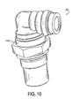
- FIG. 10 is a perspective view of an embodiment of the pressure protection valve of the present invention having a vent shield
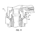
- FIG. 11 is a cross-sectional view of the valve of FIG. 10 .
- FIGS. 1-3 An embodiment of the present invention is shown in FIGS. 1-3 as a pressure protection valve 10.
- the valve 10 comprises a body 20, fixed seat 30, upper swivel portion 40, outlet 50, moving sleeve 60, and seals 70.
- the valve 10 combines a standard fluid fitting and pressure protection valve in one compact, lightweight, and high flow package.
- the upper swivel portion 40 having outlet 50 is rotatable 360 degrees while the body 20 remains fixed. This allows easy and convenient alignment of the output ports to connecting airlines, minimizing tube binding or kinking.
- the moving sleeve 60 is best shown in FIG. 3 .
- the moving sleeve 60 automatically opens and closes at set pressure differentials at the inlet and outlet against a biasing force from spring 90 positioned within the body 20 of the valve.
- the geometry of the moving sleeve 60 includes a sealing lip 62 that seals against the fixed seat 30.
- the moving sleeve 60 also includes a portion 64 having a geometry that redirects flow passing between the lip 62 and the fixed seat 30, back toward the fixed seat 30 in a manner urging the sleeve 60 away from the fixed seat 30.
- portion 64 is an annular groove formed in a leading face of the sleeve 60 leading radially inward from the sealing lip 62.
- FIGS. 4 and 5 a finite element analysis of flow is shown in the slightly open and fully open position, respectively.
- the curved sleeve geometry 64 redirects the initial fluid flow back toward the fixed seat 30 as shown by the flow vectors passing through point X, providing extra initial opening force for quicker response, minimizing the effects of the pressure drop across the seat as shown in FIG. 4 .
- the sleeve geometry 64 now has minimal effect on the fluid flow as shown by the lack of flow vectors at point X.
- Prior art valves are typically in the form of a separate unit that must be attached via fittings to the outside of the air reservoir.
- the valve 10 is shown attached to an air reservoir 180.
- the valve 10 is formed as a conventional fitting, saving space and components while locating the majority of the working components securely inside the air tank 80 and the heavy fitting body 20. If the upper swivel portion 40 of the valve 10 is dislodged due to impact, the valve can remain functional, protecting the air reservoir pressure.
- the pressure protection valve is modular such that the swivel outlet portion 50 may have multiple outlet configurations to suit customer applications while reducing overall air brake system component, complexity, and cost.
- a double outlet 50', triple outlet 50", and inline configuration 50'" is shown in FIGS. 7 , 8 , and 9 , respectively.
- the typical pressure protection valve has an atmospheric vent 80 which is completely open and subject to intrusion by dirt, road debris, and fluids - such as the vent 80 shown in FIGS. 1 and 3 .
- a pressure protection valve 10' including a vent shield 110 attached to minimize the entry of contaminants into the valve 10'.
- the geometry and flexible material allow the vent shield 110 to serve as both a shield and as a valve that reacts to the slight pressure differentials that take place as the pressure protection valve 10' shifts between open and closed states.
- the vent shield 110 seals the vent ports 80' at all times, except when the pressure protection valve is in the open / close shifting state. Being that a typical pressure protection valve normally shifts state only during vehicle start up and shut down, the vent shield 110 will keep the majority of contamination out of the valve.
- the vent 110 shield also serves as an identification band.
- the vent shield 110 is made from a flexible material that allows it to act as a valve.
- the vent 110 shield spans between a portion of the body 20 and upper swivel portion 40 in a manner that does not prevent the rotation of the upper swivel portion 40.
- the geometry of the vent shield 110 allows sealing at two points, A & B, with point A being on the upper swivel portion 40 and point B being on the body 20. These points also serve as "pivot" points when differential pressures act upon the shield 110.
Landscapes
- Engineering & Computer Science (AREA)
- General Engineering & Computer Science (AREA)
- Mechanical Engineering (AREA)
- Safety Valves (AREA)
- Valves And Accessory Devices For Braking Systems (AREA)
Description
- The present application claims the benefit of the filing date of
U.S. Provisional Patent Application Serial No. 61/232,541, filed August 10, 2009 - The present invention relates to a pressure protection valve for commercial vehicle air brake systems or other suitable applications, see for instance
US 2006/0196542 A1 . - A pneumatic system having a central air compressor is used to simultaneously provide pressurized air to two pneumatic circuits. The first pneumatic circuit is known as a critical circuit, which provides pressurized air to critical components, and the second is commonly referred to as an auxiliary circuit, which serves auxiliary components. If a leak or catastrophic failure occurs in one of the circuits, air pressure may be reduced in the critical circuit to below minimum operating parameters, thereby causing the loss of operation of critical components. To mitigate this effect, a pressure protection valve may be installed between the compressor and the auxiliary circuit. The pressure protection valve, upon sensing a loss of air pressure in the inlet of the pressure protection valve due to a leak or failure in either circuit, will isolate the auxiliary circuit from the compressor, preserving pressurized air for the critical circuit.
- Pressure protection valves are particularly used in Class 8 motor vehicles which are manufactured with a pneumatic system that includes a critical circuit and an auxiliary circuit. The critical components served by the critical circuit typically include a primary pneumatic braking system and a secondary pneumatic braking system. The auxiliary circuit typically serves auxiliary components such as an exhaust brake, air horn, or air suspension systems.
- However, existing pressure protection valves have various limitations. Existing valves have many components making them expensive to manufacture and susceptible to failures and are often difficult to install and orient to connecting air lines.
- According to an aspect of the present invention, there is provided a valve comprising: a fitting housing (20) having an inlet and an outlet fluidly connected by a fluid flow path; an output port (50) fitting swivelably attached to the outlet of the fitting; a seat member (30) fixedly positioned in the inlet of the fitting; a sleeve (60) which has a sealing lip and which can slide within the fitting housing between a first open position in which the sealing lip is spaced from the seat member and a second closed position in which the sealing lip seals against the seat member, characterised in that the sleeve has an annular groove (64) formed in the leading face of the sleeve so that fluid which flows between the seat member and the sealing lip on the sleeve when the valve is initially opened is directed into the groove which then redirects a portion of that fluid toward the fixed seat.
- Embodiments of this invention will now be described in further detail with reference to the accompanying drawings, in which:
-
FIG. 1 is a perspective view of an embodiment of the pressure protection valve of the present invention; -
FIG. 2 is a perspective view of the pressure protection valve shown inFIG. 1 showing rotation of the output port; -
FIG. 3 is an axial, cross-sectional view of the pressure protection valve shown inFIG. 1 ; -
FIG. 4 is a finite element flow model of the pressure protection valve shown inFIG. 1 in a slightly open position; -
FIG. 5 is a finite element flow model of the pressure protection valve shown inFIG. 1 in a fully open position; -
FIG. 6 is an axial, cross-sectional view of the pressure protection valve ofFIG. 1 attached to an air reservoir; -
FIG. 7 is a perspective view of an embodiment of the pressure protection valve of the present invention having two outlet ports; -
FIG. 8 is a perspective view of an embodiment of the pressure protection valve of the present invention having three outlet ports; -
FIG. 9 is a perspective view of an inline embodiment of the pressure protection valve of the present invention; -
FIG. 10 is a perspective view of an embodiment of the pressure protection valve of the present invention having a vent shield; and -
FIG. 11 is a cross-sectional view of the valve ofFIG. 10 . - An embodiment of the present invention is shown in
FIGS. 1-3 as apressure protection valve 10. Thevalve 10 comprises abody 20, fixedseat 30,upper swivel portion 40,outlet 50, movingsleeve 60, and seals 70. Thevalve 10 combines a standard fluid fitting and pressure protection valve in one compact, lightweight, and high flow package. Theupper swivel portion 40 havingoutlet 50 is rotatable 360 degrees while thebody 20 remains fixed. This allows easy and convenient alignment of the output ports to connecting airlines, minimizing tube binding or kinking. - The moving
sleeve 60 is best shown inFIG. 3 . The movingsleeve 60 automatically opens and closes at set pressure differentials at the inlet and outlet against a biasing force fromspring 90 positioned within thebody 20 of the valve. The geometry of the movingsleeve 60 includes a sealing lip 62 that seals against the fixedseat 30. The movingsleeve 60 also includes aportion 64 having a geometry that redirects flow passing between the lip 62 and the fixedseat 30, back toward the fixedseat 30 in a manner urging thesleeve 60 away from the fixedseat 30. As shown,portion 64 is an annular groove formed in a leading face of thesleeve 60 leading radially inward from the sealing lip 62. - Referring to
FIGS. 4 and5 , a finite element analysis of flow is shown in the slightly open and fully open position, respectively. As the movingsleeve 60 starts to open, thecurved sleeve geometry 64 redirects the initial fluid flow back toward the fixedseat 30 as shown by the flow vectors passing through point X, providing extra initial opening force for quicker response, minimizing the effects of the pressure drop across the seat as shown inFIG. 4 . In the fully opened position, thesleeve geometry 64 now has minimal effect on the fluid flow as shown by the lack of flow vectors at point X. - Prior art valves are typically in the form of a separate unit that must be attached via fittings to the outside of the air reservoir. Referring to
FIG. 6 , thevalve 10 is shown attached to anair reservoir 180. Thevalve 10 is formed as a conventional fitting, saving space and components while locating the majority of the working components securely inside theair tank 80 and the heavyfitting body 20. If theupper swivel portion 40 of thevalve 10 is dislodged due to impact, the valve can remain functional, protecting the air reservoir pressure. - The pressure protection valve is modular such that the
swivel outlet portion 50 may have multiple outlet configurations to suit customer applications while reducing overall air brake system component, complexity, and cost. A double outlet 50',triple outlet 50", and inline configuration 50'" is shown inFIGS. 7 ,8 , and9 , respectively. - The typical pressure protection valve has an
atmospheric vent 80 which is completely open and subject to intrusion by dirt, road debris, and fluids - such as thevent 80 shown inFIGS. 1 and3 . In the embodiment shown inFIGS. 10 and11 , a pressure protection valve 10' including avent shield 110 attached to minimize the entry of contaminants into the valve 10'. The geometry and flexible material allow thevent shield 110 to serve as both a shield and as a valve that reacts to the slight pressure differentials that take place as the pressure protection valve 10' shifts between open and closed states. Thevent shield 110 seals the vent ports 80' at all times, except when the pressure protection valve is in the open / close shifting state. Being that a typical pressure protection valve normally shifts state only during vehicle start up and shut down, thevent shield 110 will keep the majority of contamination out of the valve. Thevent 110 shield also serves as an identification band. - The
vent shield 110 is made from a flexible material that allows it to act as a valve. Thevent 110 shield spans between a portion of thebody 20 andupper swivel portion 40 in a manner that does not prevent the rotation of theupper swivel portion 40. The geometry of thevent shield 110 allows sealing at two points, A & B, with point A being on theupper swivel portion 40 and point B being on thebody 20. These points also serve as "pivot" points when differential pressures act upon theshield 110. When the pressure protection valve shifts open, positive pressure is created in the atmospheric vent port 80'. This positive pressure causes the shield to pivot at point B, and flex open at point A to vent the pressure. When the pressure is equalized, point A returns to its normal sealed position. Conversely, when the pressure protection valve shifts to a closed state, a vacuum is created in the atmospheric vent port 80' which causes the shield to pivot at point A, and allow point B to flex inward, relieving the vacuum and equalizing the pressure differential. - Although the principles, embodiments and operation of the present invention have been described in detail herein, this is not to be construed as being limited to the particular illustrative forms disclosed. They will thus become apparent to those skilled in the art that various modifications of the embodiments herein can be made without departing from the scope of the invention.
Claims (9)
- A valve comprising:a fitting housing (20) having an inlet and an outlet fluidly connected by a fluid flow path;an output port (50) fitting swivelably attached to the outlet of the fitting;a seat member (30) fixedly positioned in the inlet of the fitting;a sleeve (60) which has a sealing lip and which can slide within the fitting housing between a first open position in which the sealing lip is spaced from the seat member and a second closed position in which the sealing lip seals against the seat member, characterised in that the sleeve has an annular groove (64) formed in the leading face of the sleeve so that fluid which flows between the seat member and the sealing lip on the sleeve when the valve is initially opened is directed into the groove which then redirects a portion of that fluid toward the fixed seat.
- The valve of claim 1, further comprising a vent port (80') in the fitting housing body.
- The valve of claim 2, further comprising a vent cover (110') sealing the vent port, the vent cover movable to vent pressure through the vent port when the valve opens and to relieve pressure through the vent port when the valve closes.
- The valve of claim 3, wherein the vent cover having a first portion sealing against the fitting housing and a second portion sealing against the upper swivel portion.
- The valve of claim 4, wherein the second portion of the vent cover moves generally radially outward to allow pressure through the vent port.
- The valve of claim 4, the first portion of the vent cover moves generally radially inward to relieve pressure through the vent port.
- The valve of any preceding claim, wherein the seat member and the valve element are positioned in a portion of the fitting housing body which is insertable into a coupling of a pressurized container (180).
- The valve of claim 1, further comprising a biassing element (90) biassing the valve element toward the fixed seat.
- A pressurized container which has fitted to it a pressure protection valve which is a valve as claimed in any one of claims 1 to 8.
Applications Claiming Priority (2)
| Application Number | Priority Date | Filing Date | Title |
|---|---|---|---|
| US23254109P | 2009-08-10 | 2009-08-10 | |
| PCT/US2010/044965 WO2011019687A1 (en) | 2009-08-10 | 2010-08-10 | Pressure protection valve |
Publications (2)
| Publication Number | Publication Date |
|---|---|
| EP2464904A1 EP2464904A1 (en) | 2012-06-20 |
| EP2464904B1 true EP2464904B1 (en) | 2013-05-29 |
Family
ID=43064373
Family Applications (1)
| Application Number | Title | Priority Date | Filing Date |
|---|---|---|---|
| EP20100747730 Active EP2464904B1 (en) | 2009-08-10 | 2010-08-10 | Pressure protection valve |
Country Status (3)
| Country | Link |
|---|---|
| US (1) | US8985553B2 (en) |
| EP (1) | EP2464904B1 (en) |
| WO (1) | WO2011019687A1 (en) |
Families Citing this family (3)
| Publication number | Priority date | Publication date | Assignee | Title |
|---|---|---|---|---|
| US9476599B2 (en) * | 2013-08-04 | 2016-10-25 | Triteck Limited | Hot water storage unit, relief device and method of making a hot water storage unit |
| USD928916S1 (en) * | 2019-11-06 | 2021-08-24 | Doosan Mobility Innovation Inc. | Regulator valve |
| USD928289S1 (en) * | 2019-11-18 | 2021-08-17 | Doosan Mobility Innovation Inc. | Regulator valve |
Family Cites Families (16)
| Publication number | Priority date | Publication date | Assignee | Title |
|---|---|---|---|---|
| US1687317A (en) | 1927-06-13 | 1928-10-09 | Nat Supply Co | Gas-lift pumping apparatus |
| US1854518A (en) * | 1930-05-28 | 1932-04-19 | John Q Little | Cement barrel |
| US2101938A (en) * | 1937-09-01 | 1937-12-14 | Chipman H Giberson | Lubricated swivel pipe joint |
| US2525799A (en) * | 1947-11-04 | 1950-10-17 | Marvin S Hecker | Oxygen check valve |
| US2655391A (en) * | 1950-05-08 | 1953-10-13 | Earle R Atkins | High-temperature and pressure packing gland |
| US3236256A (en) | 1963-01-28 | 1966-02-22 | Bendix Westinghouse Automotive | Pressure protection valve |
| US3630197A (en) * | 1968-11-29 | 1971-12-28 | Tukiko Hirano | Respiratory valve of nonrebreathing type for use in anaesthesia apparatus |
| US3993361A (en) | 1974-03-28 | 1976-11-23 | Wagner Electric Corporation | Pressure protection valve and system |
| US4215718A (en) | 1978-11-22 | 1980-08-05 | Fosdick Dale P | Relief valve |
| US4565211A (en) * | 1984-01-23 | 1986-01-21 | Aeroquip Corporation | Hydraulic manifold with automatic flow control |
| DE8605871U1 (en) | 1986-03-04 | 1986-04-17 | GAT Grubenausbau GmbH, 5840 Schwerte | Pressure relief gas valve |
| US4688830A (en) * | 1986-06-09 | 1987-08-25 | Fastest, Inc. | Externally threaded quick connect coupling having integral fluid pressure assisted seal |
| US4856756A (en) | 1988-10-31 | 1989-08-15 | Combs Linsey L | Well bottom release valve |
| US7213611B2 (en) | 2004-12-15 | 2007-05-08 | Eaton Corporation | Valve assembly |
| US20060196542A1 (en) * | 2005-03-02 | 2006-09-07 | Flushtech Corporation | Vacuum breaker |
| FR2917147B1 (en) | 2007-06-11 | 2009-08-21 | Perolo Sa Sa | SAFETY VALVE AND TANK CONTAINER EQUIPPED WITH SUCH A VALVE |
-
2010
- 2010-08-10 WO PCT/US2010/044965 patent/WO2011019687A1/en not_active Ceased
- 2010-08-10 EP EP20100747730 patent/EP2464904B1/en active Active
- 2010-08-10 US US13/387,794 patent/US8985553B2/en active Active
Also Published As
| Publication number | Publication date |
|---|---|
| US20120186668A1 (en) | 2012-07-26 |
| EP2464904A1 (en) | 2012-06-20 |
| US8985553B2 (en) | 2015-03-24 |
| WO2011019687A1 (en) | 2011-02-17 |
Similar Documents
| Publication | Publication Date | Title |
|---|---|---|
| CA2728611C (en) | Pressure controlled three way valve device | |
| US4077433A (en) | Quick coupling device | |
| EP2901050B1 (en) | Slam shut safety device with guided plug support | |
| SE534920C2 (en) | Valve device for a differential pressure transducer with safety valve | |
| US20140299806A1 (en) | Shut-off valve | |
| US8985553B2 (en) | Pressure protection valve | |
| EP3864330B1 (en) | Slam-shut safety assembly for providing redundant safety shutoff | |
| JPS6120751B2 (en) | ||
| US6397887B1 (en) | Valve housing with integral downstream purge | |
| CA2884837C (en) | Slam shut safety device with guided valve disc | |
| WO2015157228A1 (en) | Block-and-bleed fluid regulating | |
| US20060124174A1 (en) | Valve assembly | |
| US20120180888A1 (en) | High flow service valve | |
| US7343882B2 (en) | Fluid valve | |
| EP4190652B1 (en) | Check valve with integrated venting element | |
| US6378548B1 (en) | Varying size diaphragm valve assemblies utilizing diaphragm of uniform size | |
| CN112334691A (en) | Bleed system with pressure relief valve | |
| WO2013126099A1 (en) | Air valve and method for refurbishing an air valve | |
| CN117321325A (en) | Valves for fluid lines in vehicles | |
| US20230182048A1 (en) | Fluid connection element | |
| WO2010091378A1 (en) | C0mbination solenoid check valve | |
| JPS6318061B2 (en) | ||
| JPS6039627Y2 (en) | gas supply equipment | |
| US4815702A (en) | Gate valve with poppet closure | |
| JP2001056065A (en) | Emergency shut-off valve |
Legal Events
| Date | Code | Title | Description |
|---|---|---|---|
| PUAI | Public reference made under article 153(3) epc to a published international application that has entered the european phase |
Free format text: ORIGINAL CODE: 0009012 |
|
| 17P | Request for examination filed |
Effective date: 20120117 |
|
| AK | Designated contracting states |
Kind code of ref document: A1 Designated state(s): AL AT BE BG CH CY CZ DE DK EE ES FI FR GB GR HR HU IE IS IT LI LT LU LV MC MK MT NL NO PL PT RO SE SI SK SM TR |
|
| DAX | Request for extension of the european patent (deleted) | ||
| GRAP | Despatch of communication of intention to grant a patent |
Free format text: ORIGINAL CODE: EPIDOSNIGR1 |
|
| GRAS | Grant fee paid |
Free format text: ORIGINAL CODE: EPIDOSNIGR3 |
|
| GRAA | (expected) grant |
Free format text: ORIGINAL CODE: 0009210 |
|
| AK | Designated contracting states |
Kind code of ref document: B1 Designated state(s): AL AT BE BG CH CY CZ DE DK EE ES FI FR GB GR HR HU IE IS IT LI LT LU LV MC MK MT NL NO PL PT RO SE SI SK SM TR |
|
| REG | Reference to a national code |
Ref country code: GB Ref legal event code: FG4D |
|
| REG | Reference to a national code |
Ref country code: CH Ref legal event code: EP |
|
| REG | Reference to a national code |
Ref country code: AT Ref legal event code: REF Ref document number: 614625 Country of ref document: AT Kind code of ref document: T Effective date: 20130615 |
|
| REG | Reference to a national code |
Ref country code: IE Ref legal event code: FG4D |
|
| REG | Reference to a national code |
Ref country code: DE Ref legal event code: R096 Ref document number: 602010007410 Country of ref document: DE Effective date: 20130801 |
|
| REG | Reference to a national code |
Ref country code: AT Ref legal event code: MK05 Ref document number: 614625 Country of ref document: AT Kind code of ref document: T Effective date: 20130529 |
|
| REG | Reference to a national code |
Ref country code: LT Ref legal event code: MG4D |
|
| PG25 | Lapsed in a contracting state [announced via postgrant information from national office to epo] |
Ref country code: IS Free format text: LAPSE BECAUSE OF FAILURE TO SUBMIT A TRANSLATION OF THE DESCRIPTION OR TO PAY THE FEE WITHIN THE PRESCRIBED TIME-LIMIT Effective date: 20130929 Ref country code: LT Free format text: LAPSE BECAUSE OF FAILURE TO SUBMIT A TRANSLATION OF THE DESCRIPTION OR TO PAY THE FEE WITHIN THE PRESCRIBED TIME-LIMIT Effective date: 20130529 Ref country code: AT Free format text: LAPSE BECAUSE OF FAILURE TO SUBMIT A TRANSLATION OF THE DESCRIPTION OR TO PAY THE FEE WITHIN THE PRESCRIBED TIME-LIMIT Effective date: 20130529 Ref country code: GR Free format text: LAPSE BECAUSE OF FAILURE TO SUBMIT A TRANSLATION OF THE DESCRIPTION OR TO PAY THE FEE WITHIN THE PRESCRIBED TIME-LIMIT Effective date: 20130830 Ref country code: NO Free format text: LAPSE BECAUSE OF FAILURE TO SUBMIT A TRANSLATION OF THE DESCRIPTION OR TO PAY THE FEE WITHIN THE PRESCRIBED TIME-LIMIT Effective date: 20130829 Ref country code: SE Free format text: LAPSE BECAUSE OF FAILURE TO SUBMIT A TRANSLATION OF THE DESCRIPTION OR TO PAY THE FEE WITHIN THE PRESCRIBED TIME-LIMIT Effective date: 20130529 Ref country code: SI Free format text: LAPSE BECAUSE OF FAILURE TO SUBMIT A TRANSLATION OF THE DESCRIPTION OR TO PAY THE FEE WITHIN THE PRESCRIBED TIME-LIMIT Effective date: 20130529 Ref country code: ES Free format text: LAPSE BECAUSE OF FAILURE TO SUBMIT A TRANSLATION OF THE DESCRIPTION OR TO PAY THE FEE WITHIN THE PRESCRIBED TIME-LIMIT Effective date: 20130909 Ref country code: PT Free format text: LAPSE BECAUSE OF FAILURE TO SUBMIT A TRANSLATION OF THE DESCRIPTION OR TO PAY THE FEE WITHIN THE PRESCRIBED TIME-LIMIT Effective date: 20130930 Ref country code: FI Free format text: LAPSE BECAUSE OF FAILURE TO SUBMIT A TRANSLATION OF THE DESCRIPTION OR TO PAY THE FEE WITHIN THE PRESCRIBED TIME-LIMIT Effective date: 20130529 |
|
| REG | Reference to a national code |
Ref country code: NL Ref legal event code: VDEP Effective date: 20130529 |
|
| PG25 | Lapsed in a contracting state [announced via postgrant information from national office to epo] |
Ref country code: PL Free format text: LAPSE BECAUSE OF FAILURE TO SUBMIT A TRANSLATION OF THE DESCRIPTION OR TO PAY THE FEE WITHIN THE PRESCRIBED TIME-LIMIT Effective date: 20130529 Ref country code: BG Free format text: LAPSE BECAUSE OF FAILURE TO SUBMIT A TRANSLATION OF THE DESCRIPTION OR TO PAY THE FEE WITHIN THE PRESCRIBED TIME-LIMIT Effective date: 20130829 Ref country code: HR Free format text: LAPSE BECAUSE OF FAILURE TO SUBMIT A TRANSLATION OF THE DESCRIPTION OR TO PAY THE FEE WITHIN THE PRESCRIBED TIME-LIMIT Effective date: 20130529 |
|
| PG25 | Lapsed in a contracting state [announced via postgrant information from national office to epo] |
Ref country code: LV Free format text: LAPSE BECAUSE OF FAILURE TO SUBMIT A TRANSLATION OF THE DESCRIPTION OR TO PAY THE FEE WITHIN THE PRESCRIBED TIME-LIMIT Effective date: 20130529 |
|
| PG25 | Lapsed in a contracting state [announced via postgrant information from national office to epo] |
Ref country code: EE Free format text: LAPSE BECAUSE OF FAILURE TO SUBMIT A TRANSLATION OF THE DESCRIPTION OR TO PAY THE FEE WITHIN THE PRESCRIBED TIME-LIMIT Effective date: 20130529 Ref country code: DK Free format text: LAPSE BECAUSE OF FAILURE TO SUBMIT A TRANSLATION OF THE DESCRIPTION OR TO PAY THE FEE WITHIN THE PRESCRIBED TIME-LIMIT Effective date: 20130529 Ref country code: CZ Free format text: LAPSE BECAUSE OF FAILURE TO SUBMIT A TRANSLATION OF THE DESCRIPTION OR TO PAY THE FEE WITHIN THE PRESCRIBED TIME-LIMIT Effective date: 20130529 Ref country code: SK Free format text: LAPSE BECAUSE OF FAILURE TO SUBMIT A TRANSLATION OF THE DESCRIPTION OR TO PAY THE FEE WITHIN THE PRESCRIBED TIME-LIMIT Effective date: 20130529 Ref country code: BE Free format text: LAPSE BECAUSE OF FAILURE TO SUBMIT A TRANSLATION OF THE DESCRIPTION OR TO PAY THE FEE WITHIN THE PRESCRIBED TIME-LIMIT Effective date: 20130529 |
|
| PG25 | Lapsed in a contracting state [announced via postgrant information from national office to epo] |
Ref country code: RO Free format text: LAPSE BECAUSE OF FAILURE TO SUBMIT A TRANSLATION OF THE DESCRIPTION OR TO PAY THE FEE WITHIN THE PRESCRIBED TIME-LIMIT Effective date: 20130529 Ref country code: NL Free format text: LAPSE BECAUSE OF FAILURE TO SUBMIT A TRANSLATION OF THE DESCRIPTION OR TO PAY THE FEE WITHIN THE PRESCRIBED TIME-LIMIT Effective date: 20130529 Ref country code: IT Free format text: LAPSE BECAUSE OF FAILURE TO SUBMIT A TRANSLATION OF THE DESCRIPTION OR TO PAY THE FEE WITHIN THE PRESCRIBED TIME-LIMIT Effective date: 20130529 |
|
| PLBE | No opposition filed within time limit |
Free format text: ORIGINAL CODE: 0009261 |
|
| STAA | Information on the status of an ep patent application or granted ep patent |
Free format text: STATUS: NO OPPOSITION FILED WITHIN TIME LIMIT |
|
| PG25 | Lapsed in a contracting state [announced via postgrant information from national office to epo] |
Ref country code: MC Free format text: LAPSE BECAUSE OF FAILURE TO SUBMIT A TRANSLATION OF THE DESCRIPTION OR TO PAY THE FEE WITHIN THE PRESCRIBED TIME-LIMIT Effective date: 20130529 |
|
| 26N | No opposition filed |
Effective date: 20140303 |
|
| REG | Reference to a national code |
Ref country code: IE Ref legal event code: MM4A |
|
| REG | Reference to a national code |
Ref country code: DE Ref legal event code: R097 Ref document number: 602010007410 Country of ref document: DE Effective date: 20140303 |
|
| PG25 | Lapsed in a contracting state [announced via postgrant information from national office to epo] |
Ref country code: IE Free format text: LAPSE BECAUSE OF NON-PAYMENT OF DUE FEES Effective date: 20130810 |
|
| REG | Reference to a national code |
Ref country code: CH Ref legal event code: PL |
|
| PG25 | Lapsed in a contracting state [announced via postgrant information from national office to epo] |
Ref country code: CH Free format text: LAPSE BECAUSE OF NON-PAYMENT OF DUE FEES Effective date: 20140831 Ref country code: LI Free format text: LAPSE BECAUSE OF NON-PAYMENT OF DUE FEES Effective date: 20140831 |
|
| PG25 | Lapsed in a contracting state [announced via postgrant information from national office to epo] |
Ref country code: SM Free format text: LAPSE BECAUSE OF FAILURE TO SUBMIT A TRANSLATION OF THE DESCRIPTION OR TO PAY THE FEE WITHIN THE PRESCRIBED TIME-LIMIT Effective date: 20130529 |
|
| PG25 | Lapsed in a contracting state [announced via postgrant information from national office to epo] |
Ref country code: TR Free format text: LAPSE BECAUSE OF FAILURE TO SUBMIT A TRANSLATION OF THE DESCRIPTION OR TO PAY THE FEE WITHIN THE PRESCRIBED TIME-LIMIT Effective date: 20130529 Ref country code: MT Free format text: LAPSE BECAUSE OF FAILURE TO SUBMIT A TRANSLATION OF THE DESCRIPTION OR TO PAY THE FEE WITHIN THE PRESCRIBED TIME-LIMIT Effective date: 20130529 Ref country code: CY Free format text: LAPSE BECAUSE OF FAILURE TO SUBMIT A TRANSLATION OF THE DESCRIPTION OR TO PAY THE FEE WITHIN THE PRESCRIBED TIME-LIMIT Effective date: 20130529 |
|
| PG25 | Lapsed in a contracting state [announced via postgrant information from national office to epo] |
Ref country code: HU Free format text: LAPSE BECAUSE OF FAILURE TO SUBMIT A TRANSLATION OF THE DESCRIPTION OR TO PAY THE FEE WITHIN THE PRESCRIBED TIME-LIMIT; INVALID AB INITIO Effective date: 20100810 Ref country code: MK Free format text: LAPSE BECAUSE OF FAILURE TO SUBMIT A TRANSLATION OF THE DESCRIPTION OR TO PAY THE FEE WITHIN THE PRESCRIBED TIME-LIMIT Effective date: 20130529 Ref country code: LU Free format text: LAPSE BECAUSE OF NON-PAYMENT OF DUE FEES Effective date: 20130810 |
|
| REG | Reference to a national code |
Ref country code: FR Ref legal event code: PLFP Year of fee payment: 7 |
|
| REG | Reference to a national code |
Ref country code: FR Ref legal event code: PLFP Year of fee payment: 8 |
|
| REG | Reference to a national code |
Ref country code: FR Ref legal event code: PLFP Year of fee payment: 9 |
|
| PG25 | Lapsed in a contracting state [announced via postgrant information from national office to epo] |
Ref country code: AL Free format text: LAPSE BECAUSE OF FAILURE TO SUBMIT A TRANSLATION OF THE DESCRIPTION OR TO PAY THE FEE WITHIN THE PRESCRIBED TIME-LIMIT Effective date: 20130529 |
|
| P01 | Opt-out of the competence of the unified patent court (upc) registered |
Effective date: 20230524 |
|
| PGFP | Annual fee paid to national office [announced via postgrant information from national office to epo] |
Ref country code: DE Payment date: 20250827 Year of fee payment: 16 |
|
| PGFP | Annual fee paid to national office [announced via postgrant information from national office to epo] |
Ref country code: GB Payment date: 20250827 Year of fee payment: 16 |
|
| PGFP | Annual fee paid to national office [announced via postgrant information from national office to epo] |
Ref country code: FR Payment date: 20250825 Year of fee payment: 16 |