EP2464146A1 - Apparatus and method for decomposing an input signal using a pre-calculated reference curve - Google Patents
Apparatus and method for decomposing an input signal using a pre-calculated reference curve Download PDFInfo
- Publication number
- EP2464146A1 EP2464146A1 EP11165746A EP11165746A EP2464146A1 EP 2464146 A1 EP2464146 A1 EP 2464146A1 EP 11165746 A EP11165746 A EP 11165746A EP 11165746 A EP11165746 A EP 11165746A EP 2464146 A1 EP2464146 A1 EP 2464146A1
- Authority
- EP
- European Patent Office
- Prior art keywords
- signal
- analysis
- channels
- frequency
- analyzer
- Prior art date
- Legal status (The legal status is an assumption and is not a legal conclusion. Google has not performed a legal analysis and makes no representation as to the accuracy of the status listed.)
- Withdrawn
Links
- 238000000034 method Methods 0.000 title claims abstract description 40
- 238000004458 analytical method Methods 0.000 claims abstract description 104
- 230000001419 dependent effect Effects 0.000 claims abstract description 43
- 230000008569 process Effects 0.000 claims abstract description 5
- 238000012545 processing Methods 0.000 claims description 33
- 238000000354 decomposition reaction Methods 0.000 claims description 19
- 238000004590 computer program Methods 0.000 claims description 11
- 238000001228 spectrum Methods 0.000 description 17
- 230000006870 function Effects 0.000 description 12
- 238000013459 approach Methods 0.000 description 11
- 210000003128 head Anatomy 0.000 description 10
- 230000000875 corresponding effect Effects 0.000 description 9
- 238000001914 filtration Methods 0.000 description 9
- 230000033458 reproduction Effects 0.000 description 9
- 238000004364 calculation method Methods 0.000 description 8
- 230000000694 effects Effects 0.000 description 8
- 230000008447 perception Effects 0.000 description 8
- 238000010586 diagram Methods 0.000 description 6
- 238000005259 measurement Methods 0.000 description 6
- 230000005236 sound signal Effects 0.000 description 6
- 230000005540 biological transmission Effects 0.000 description 5
- 238000000605 extraction Methods 0.000 description 5
- 238000009877 rendering Methods 0.000 description 5
- 230000004044 response Effects 0.000 description 5
- 210000005069 ears Anatomy 0.000 description 4
- 230000008901 benefit Effects 0.000 description 3
- 238000009530 blood pressure measurement Methods 0.000 description 3
- 230000002596 correlated effect Effects 0.000 description 3
- 238000010219 correlation analysis Methods 0.000 description 3
- 238000005314 correlation function Methods 0.000 description 3
- 238000009795 derivation Methods 0.000 description 3
- 238000009792 diffusion process Methods 0.000 description 3
- 238000002156 mixing Methods 0.000 description 3
- 230000010363 phase shift Effects 0.000 description 3
- 230000001902 propagating effect Effects 0.000 description 3
- 238000004088 simulation Methods 0.000 description 3
- 230000003595 spectral effect Effects 0.000 description 3
- 230000003044 adaptive effect Effects 0.000 description 2
- 230000002238 attenuated effect Effects 0.000 description 2
- 230000001427 coherent effect Effects 0.000 description 2
- 238000006880 cross-coupling reaction Methods 0.000 description 2
- 210000000883 ear external Anatomy 0.000 description 2
- 210000003027 ear inner Anatomy 0.000 description 2
- 210000000959 ear middle Anatomy 0.000 description 2
- 238000011156 evaluation Methods 0.000 description 2
- 230000000763 evoking effect Effects 0.000 description 2
- 230000001965 increasing effect Effects 0.000 description 2
- 230000010354 integration Effects 0.000 description 2
- 230000004807 localization Effects 0.000 description 2
- 238000012986 modification Methods 0.000 description 2
- 230000004048 modification Effects 0.000 description 2
- 238000012546 transfer Methods 0.000 description 2
- 238000012935 Averaging Methods 0.000 description 1
- 238000005311 autocorrelation function Methods 0.000 description 1
- 238000005452 bending Methods 0.000 description 1
- 230000015572 biosynthetic process Effects 0.000 description 1
- 239000002775 capsule Substances 0.000 description 1
- 230000008859 change Effects 0.000 description 1
- 238000004891 communication Methods 0.000 description 1
- 238000007906 compression Methods 0.000 description 1
- 230000006835 compression Effects 0.000 description 1
- 238000005094 computer simulation Methods 0.000 description 1
- 230000001934 delay Effects 0.000 description 1
- 230000003111 delayed effect Effects 0.000 description 1
- 210000000613 ear canal Anatomy 0.000 description 1
- 238000005516 engineering process Methods 0.000 description 1
- 238000009472 formulation Methods 0.000 description 1
- 238000009499 grossing Methods 0.000 description 1
- 238000013507 mapping Methods 0.000 description 1
- 239000011159 matrix material Substances 0.000 description 1
- 239000000203 mixture Substances 0.000 description 1
- 238000007781 pre-processing Methods 0.000 description 1
- 238000000513 principal component analysis Methods 0.000 description 1
- 238000011160 research Methods 0.000 description 1
- 238000000926 separation method Methods 0.000 description 1
- 238000012360 testing method Methods 0.000 description 1
- 230000007704 transition Effects 0.000 description 1
Images


Classifications
-
- H—ELECTRICITY
- H04—ELECTRIC COMMUNICATION TECHNIQUE
- H04S—STEREOPHONIC SYSTEMS
- H04S3/00—Systems employing more than two channels, e.g. quadraphonic
-
- H—ELECTRICITY
- H04—ELECTRIC COMMUNICATION TECHNIQUE
- H04R—LOUDSPEAKERS, MICROPHONES, GRAMOPHONE PICK-UPS OR LIKE ACOUSTIC ELECTROMECHANICAL TRANSDUCERS; DEAF-AID SETS; PUBLIC ADDRESS SYSTEMS
- H04R5/00—Stereophonic arrangements
- H04R5/04—Circuit arrangements, e.g. for selective connection of amplifier inputs/outputs to loudspeakers, for loudspeaker detection, or for adaptation of settings to personal preferences or hearing impairments
-
- G—PHYSICS
- G10—MUSICAL INSTRUMENTS; ACOUSTICS
- G10L—SPEECH ANALYSIS TECHNIQUES OR SPEECH SYNTHESIS; SPEECH RECOGNITION; SPEECH OR VOICE PROCESSING TECHNIQUES; SPEECH OR AUDIO CODING OR DECODING
- G10L19/00—Speech or audio signals analysis-synthesis techniques for redundancy reduction, e.g. in vocoders; Coding or decoding of speech or audio signals, using source filter models or psychoacoustic analysis
- G10L19/02—Speech or audio signals analysis-synthesis techniques for redundancy reduction, e.g. in vocoders; Coding or decoding of speech or audio signals, using source filter models or psychoacoustic analysis using spectral analysis, e.g. transform vocoders or subband vocoders
-
- H—ELECTRICITY
- H04—ELECTRIC COMMUNICATION TECHNIQUE
- H04S—STEREOPHONIC SYSTEMS
- H04S3/00—Systems employing more than two channels, e.g. quadraphonic
- H04S3/008—Systems employing more than two channels, e.g. quadraphonic in which the audio signals are in digital form, i.e. employing more than two discrete digital channels
-
- H—ELECTRICITY
- H04—ELECTRIC COMMUNICATION TECHNIQUE
- H04S—STEREOPHONIC SYSTEMS
- H04S2400/00—Details of stereophonic systems covered by H04S but not provided for in its groups
- H04S2400/03—Aspects of down-mixing multi-channel audio to configurations with lower numbers of playback channels, e.g. 7.1 -> 5.1
-
- H—ELECTRICITY
- H04—ELECTRIC COMMUNICATION TECHNIQUE
- H04S—STEREOPHONIC SYSTEMS
- H04S2400/00—Details of stereophonic systems covered by H04S but not provided for in its groups
- H04S2400/15—Aspects of sound capture and related signal processing for recording or reproduction
Definitions
- the present invention relates to audio processing and, in particular to audio signal decomposition into different components such as perceptually distinct components.
- the human auditory system senses sound from all directions.
- the perceived auditory (the adjective auditory denotes what is perceived, while the word sound will be used to describe physical phenomena) environment creates an impression of the acoustic properties of the surrounding space and the occurring sound events.
- the auditory impression perceived in a specific sound field can (at least partially) be modeled considering three different types of signals at the car entrances: The direct sound, early reflections, and diffuse reflections. These signals contribute to the formation of a perceived auditory spatial image.
- Direct sound denotes the waves of each sound event that first reach the listener directly from a sound source without disturbances. It is characteristic for the sound source and provides the least-compromised information about the direction of incidence of the sound event.
- the primary cues for estimating the direction of a sound source in the horizontal plane are differences between the left and right ear input signals, namely interaural time differences (ITDs) and interaural level differences (ILDs).
- ITDs interaural time differences
- ILDs interaural level differences
- the reflected sound contributes to distance perception, and to the auditory spatial impression, which is composed of at least two components: apparent source width (ASW) (Another commonly used term for ASW is auditory spaciousness) and listener envelopment (LEV).
- ASW apparent source width
- LEV listener envelopment
- ASW is defined as a broadening of the apparent width of a sound source and is primarily determined by early lateral reflections.
- LEV refers to the listener's sense of being enveloped by sound and is determined primarily by late-arriving reflections.
- the goal of electroacoustic stereophonic sound reproduction is to evoke the perception of a pleasing auditory spatial image. This can have a natural or architectural reference (e.g. the recording of a concert in a hall), or it may be a sound field that is not existent in reality (e.g. electroacoustic music).
- the goal is to evoke the perception of a continuous, diffuse sound field using only a discrete number of transducers. That is, creating sound fields where no direction of sound arrival can be estimated and especially no single transducer can be localized.
- the subjective diffuseness of synthetic sound fields can be evaluated in subjective tests.
- Stereophonic sound reproductions aim at evoking the perception of a continuous sound field using only a discrete number of transducers.
- the features desired the most are directional stability of localized sources and realistic rendering of the surrounding auditory environment.
- the majority of formats used today to store or transport stereophonic recordings are channel-based. Each channel conveys a signal that is intended to be played back over an associated loudspeaker at as specific position.
- a specific auditory image is designed during the recording or mixing process. This image is accurately recreated if the loudspeaker setup used for reproduction resembles the target setup that the recording was designed for.
- the described direct/ambient signal decompositions are not readily applicable to multi-channel surround signals. It is not easy to formulate a signal model and filtering to obtain from N audio channels the corresponding N direct sound and N ambient sound channels.
- the simple signal model used in the stereo case see e.g. Christof Faller, "Multiple-loudspeaker playback of stereo signals," Journal of the Audio Engineering Society, vol. 54, no. 11, pp. 1051-1064, November 2006 , assuming direct sound to be correlated amongst all channels, does not capture the diversity of channel relations that can exist between surround signal channels.
- stereophonic sound reproduction is to evoke the perception of a continuous sound field using only a limited number of transmission channels and transducers.
- Two loudspeakers are the minimum requirement for spatial sound reproduction.
- Modem consumer systems often offer a larger number of reproduction channels.
- stereophonic signals independent of the number of channels
- Correct perception of the intended auditory image is usually only possible in the ideal point of observation in the playback setup the recording was intended for.
- a decomposition of audio signals into perceptually distinct components is necessary for high quality signal modification, enhancement, adaptive playback, and perceptual coding.
- a number of methods have recently been proposed that allow the manipulation and/or extraction of perceptually distinct signal components from two-channel input signals. Since input signals with more than two channels become more and more common, the described manipulations are desirable also for multichannel input signals. However, most of the concepts described for two-channel input can not easily be extended to work with input signals with an arbitrary number of channels.
- a further reference is C. Avendano and J.-M. Jot, "A frequency-domain approach to multichannel upmix", Journal of the Audio Engineering Society, vol. 52, no. 7/8, pp. 740-749, 2004 .
- the reference provides an approach which involves creating a time-frequency mask to extract the ambience from a stereo input signal.
- the mask is based on the cross-correlation between the left-and right channel signals, however, so this approach is not immediately applicable to the problem of extracting ambience from an arbitrary multichannel input.
- To use any such correlation-based method in this higher-order case would call for a hierarchical pairwise correlation analysis, which would entail a significant computational cost, or some alternate measure of multichannel correlation.
- SIRR Spatial Impulse Response Rendering
- Wiener-filtering approach can provide useful results for noise cancellation in reverberant rooms, it can be computationally inefficient and it is, for some instances, not so useful for signal decomposition.
- the present invention is based on the finding that a particular efficiency for the purpose of signal decomposition is obtained when the signal analysis is performed based on the pre-calculated frequency-dependent similarity curve as a reference curve.
- the term similarity includes the correlation and the coherence, where - in a strict - mathematical sense, the correlation is calculated between two signals without an additional time shift and the coherence is calculated by shifting the two signals in time/phase so that the signals have a maximum correlation and the actual correlation over frequency is then calculated with the time/phase shift applied.
- similarity, correlation and coherence are considered to mean the same, i.e., a quantitative degree of similarity between two signals, e.g., where a higher absolute value of the similarity means that the two signals are more similar and a lower absolute value of the similarity means that the two signals are less similar.
- the other preferred alternative is to simply calculate the similarity curve under the assumption of independent signals. In this case, any signals are actually not necessary, since the result is signal-independent.
- the signal decomposition using a reference curve for the signal analysis can be applied for stereo processing, i.e., for decomposing a stereo signal.
- this procedure can also be implemented together with a downmixer for decomposing multichannel signals.
- this procedure can also be implemented for multichannel signals without using a downmixer when a pair-wise evaluation of signals in a hierarchical way is envisaged.
- the multi-channel input signal having at least three input channels is processed by a downmixer for downmixing the input signal to obtain a downmixed signal.
- the downmixed signal has a number of downmix channels which is smaller than the number of input channels and, preferably, is two. Then, the analysis of the input signal is performed on the downmixed signal rather than on the input signal directly and the analysis results in an analysis result.
- this analysis result is not applied to the downmixed signal, but is applied to the input signal or, alternatively, to a signal derived from the input signal where this signal derived from the input signal may be an upmix signal or, depending on the number of channels of the input signals, also a downmix signal, but this signal derived from the input signal will be different from the downmixed signal, on which the analysis has been performed.
- the downmix signal on which the analysis is performed, might be a stereo downmix having two channels.
- the analysis results are then applied to the 5.1 input signal directly, to a higher upmix such as a 7.1 output signal or to a multi-channel downmix of the input signal having for example only three channels, which are the left channel, the center channel and the right channel, when only a three channel audio rendering apparatus is at hand.
- a higher upmix such as a 7.1 output signal or to a multi-channel downmix of the input signal having for example only three channels, which are the left channel, the center channel and the right channel, when only a three channel audio rendering apparatus is at hand.
- the signal on which the analysis results are applied by the signal processor is different from the downmixed signal that the analysis has been performed on and typically has more channels than the downmixed signal, on which the analysis with respect to the signal components is performed on.
- any signal components in the individual input channels also occur in the downmixed channels, since a downmix typically consists of an addition of input channels in different ways.
- One straightforward downmix is, for example, that the individual input channels are weighted as required by a downmix rule or a downmix matrix and are then added together after having been weighted.
- An alternative downmix consists of filtering the input channels with certain filters such as HRTF filters and the downmix is performed by using filtered signals, i.e. the signals filtered by HRTF filters as known in the art.
- embodiments of the present invention describe a novel concept to extract perceptually distinct components from arbitrary input signals by considering an analysis signal, while the result of the analysis is applied to the input signal.
- an analysis signal can be gained e.g. by considering a propagation model of the channels or loudspeaker signals to the ears. This is in part motivated by the fact that the human auditory system also uses solely two sensors (the left and right ear) to evaluate sound fields.
- the extraction of perceptually distinct components is basically reduced to the consideration of an analysis signal that will be denoted as downmix in the following.
- the term downmix is used for any pre-processing of the multichannel signal resulting in an analysis signal (this may include e.g. a propagation model, HRTFs, BRIRs, simple cross-factor downmix).
- the ideal inter-channel relations can be defined for the downmixed format and such, an analysis of this analysis signal is sufficient to generate a weighting mask (or multiple weighting masks) for the decomposition of multichannel signals.
- the multi-channel problem is simplified by using a stereo downmix of a surround signal and applying a direct/ambient analysis to the downmix. Based on the result, i.e. short-time power spectra estimations of direct and ambient sounds, filters are derived for decomposing a N-channel signal to N direct sound and N ambient sound channels.
- the present invention is advantageous due to the fact that signal analysis is applied on a smaller number of channels, which significantly reduces the processing time required, so that the inventive concept can even be applied in real time applications for upmixing or downmixing or any other signal processing operation where different components such as perceptually different components of a signal are required.
- a further advantage of the present invention is that although a downmix is performed it has been found out that this does not deteriorate the detectability of perceptually distinct components in the input signal. Stated differently, even when input channels are downmixed, the individual signal components can nevertheless be separated to a large extent. Furthermore, the downmix operates as a kind of "collection" of all signal components of all input channels into two channels and the single analysis applied on these "collected" downmixed signals provides a unique result which no longer has to be interpreted and can be directly used for signal processing.
- Fig. 1 illustrates an apparatus for decomposing an input signal 10 having a number of at least three input channels or, generally, N input channels. These input channels are input into a downmixer 12 for downmixing the input signal to obtain a downmixed signal 14, wherein the downmixer 12 is arranged for downmixing so that a number of downmix channels of the downmixed signal 14, which is indicated by "m", is at least two and smaller than the number of input channels of the input signal 10.
- the m downmix channels are input into an analyzer 16 for analyzing the downmixed signal to derive an analysis result 18.
- the analysis result 18 is input into a signal processor 20, where the signal processor is arranged for processing the input signal 10 or a signal derived from the input signal by a signal deriver 22 using the analysis result, wherein the signal processor 20 is configured for applying the analysis results to the input channels or to channels of the signal 24 derived from the input signal to obtain a decomposed signal 26.
- a number of input channels is n
- the number of downmix channels is m
- the number of derived channels is 1
- the number of output channels is equal to 1
- the signal deriver 22 does not exist then the input signal is directly processed by the signal processor and then the number of channels of the decomposed signal 26 indicated by "1" in Fig. 1 will be equal to n.
- Fig. 1 illustrates two different examples. One example does not have the signal deriver 22 and the input signal is directly applied to the signal processor 20.
- the other example is that the signal deriver 22 is implemented and, then, the derived signal 24 rather than the input signal 10 is processed by the signal processor 20.
- the signal deriver may, for example, be an audio channel mixer such as an upmixer for generating more output channels. In this case 1 would be greater than n.
- the signal deriver could be another audio processor which performs weighting, delay or anything else to the input channels and in this case the number of output channels of 1 of the signal deriver 22 would be equal to the number n of input channels.
- the signal deriver could be a downmixer which reduces the number of channels from the input signal to the derived signal.
- the number 1 is still greater than the number m of downmixed channels in order to have one of the advantages of the present invention, i.e. that the signal analysis is applied to a smaller number of channel signals.
- the analyzer is operative to analyze the downmixed signal with respect to perceptually distinct components. These perceptually distinct components can be independent components in the individual channels on the one hand, and dependent components on the other hand.
- Alternative signal components to be analyzed by the present invention are direct components on the one hand and ambient components on the other hand.
- Fig. 2 illustrates another aspect, where the analyzer is implemented for using a pre-calculated frequency-dependent correlation curve 16.
- the apparatus for decomposing a signal 28 having a plurality of channels comprises the analyzer 16 for analyzing a correlation between two channels of an analysis signal identical to the input signal or related to the input signal, for example, by a downmixing operation as illustrated in the context of Fig. 1 .
- the analysis signal analyzed by the analyzer 16 has at least two analysis channels, and the analyzer 16 is configured for using a pre-calculated frequency dependent correlation curve as a reference curve to determine the analysis result 18.
- the signal processor 20 can operate in the same way as discussed in the context of Fig.
- the signal processor can process a signal, from which the analysis signal is derived and the signal processing uses the analysis result to obtain a decomposed signal.
- the input signal can be identical to the analysis signal and, in this case, the analysis signal can also be a stereo signal having just two channels as illustrated in Fig. 2 .
- the analysis signal can be derived from an input signal by any kind of processing, such as downmixing as described in the context of Fig.
- the signal processor 20 can be useful to apply the signal processing to the same signal as has been input into the analyzer or the signal processor can apply a signal processing to a signal, from which the analysis signal has been derived such as indicated in the context of Fig. 1 , or the signal processor can apply a signal processing to a signal which has been derived from the analysis signal such as by upmixing or so.
- the downmix can be processed by the analyzer or a two-channel signal, which has probably not been generated by a downmix, can be processed by the signal analyzer using the pre-calculated reference curve.
- the subsequent description of implementation aspects can be applied to both aspects schematically illustrated in Fig. 1 and Fig. 2 even when certain features are only described for one aspect rather than both.
- Fig. 3 If, for example, Fig. 3 is considered, it becomes clear that the frequency-domain features of Fig. 3 are described in the context of the aspect illustrated in Fig. 1 , but it is clear that a time/frequency transform as subsequently described with respect to Fig. 3 and the inverse transform can also be applied to the implementation in Fig. 2 , which does not have a downmixer, but which has a specified analyzer that uses a pre-calculated frequency dependent correlation curve.
- the time/frequency converter would be placed to convert the analysis signal before the analysis signal is input into the analyzer, and the frequency/time converter would be placed at the output of the signal processor to convert the processed signal back into the time domain.
- the time/frequency converter might be placed at an input of the signal deriver so that the signal deriver, the analyzer, and the signal processor all operate in the frequency/subband domain.
- frequency and subband basically mean a portion in frequency of a frequency representation.
- Fig. 1 can be implemented in many different ways, but this analyzer is also, in one embodiment, implemented as the analyzer discussed in Fig. 2 , i.e. as an analyzer which uses a pre-calculated frequency-dependent correlation curve as an alternative to Wiener filtering or any other analysis method.
- Fig. 3 applies a downmix procedure to an arbitrary input signal to obtain a two-channel representation. An analysis in the time-frequency domain is performed and weighting masks are calculated that are multiplied with the time frequency representation of the input signal, as is illustrated in Fig. 3 .
- T/F denotes a time frequency transform; commonly a Short-time Fourier Transform (STFT).
- iT/F denotes the respective inverse transform.
- [ x 1 ( n ) ,...,x N ( n )] are the time domain input signals, where n is the time index.
- [ X 1 (m, i), ... , X N ( m, i )] denote the coefficients of the frequency decomposition, where m is the decomposition time index, and i is the decomposition frequency index.
- D 1 ( m,i ) ,D 2 ( m,i )] are the two channels of the downmixed signal.
- [ Y 1 ( m, i ),..., Y N ( m, i )] are the weighted frequency decompositions of each channel.
- H ij (i) are the downmix coefficients, which can be real-valued or complex-valued and the coefficients can be constant in time or time-variant.
- the downmix coefficients can be just constants or filters such as HRTF filters, reverberation filters or similar filters.
- the input signal may have an arbitrary number of channels ( N ), produced for an arbitrary target playback loudspeaker setup.
- the downmix may include HRTFs to obtain ear-input-signals, simulation of auditory filters, etc.
- the downmix may also be carried out in the time domain.).
- the difference between a reference correlation (Throughout this text, the term correlation is used as synonym for inter-channel similarity and may thus also include evaluations of time shifts, for which usually the term coherence is used. Even if time-shifts are evaluated, the resulting value may have a sign. (Commonly, the coherence is defined as having only positive values) as a function of frequency ( c ref ( ⁇ )) , and the actual correlation of the downmixed input signal (c sig ( ⁇ )) is computed. Depending on the deviation of the actual curve from the reference curve, a weighting factor for each time-frequency tile is calculated, indicating if it comprises dependent or independent components. The obtained time-frequency weighting indicates the independent components and may already be applied to each channel of the input signal to yield a multichannel signal (number of channels equal to number of input channels) including independent parts that may be perceived as either distinct or diffuse.
- the reference curve may be defined in different ways. Examples are:
- an upper threshold (C hi ( ⁇ )) and lower threshold ( c lo ( ⁇ )) can be defined (see Fig. 4 ).
- the actual bin gets a weighting indicating independent components. Above the upper threshold or below the lower threshold, the bin is indicated as dependent. This indication may be binary, or gradually (i.e. following a soft-decision function). In particular, if the upper- and lower threshold coincides with the reference curve, the applied weighting is directly related to the deviation from the reference curve.
- reference numeral 32 illustrates a time/frequency converter which can be implemented as a short-time Fourier transform or as any kind of filterbank generating subband signals such as a QMF filterbank or so.
- the output of the time/frequency converter is, for each input channel x i a spectrum for each time period of the input signal.
- the time/frequency processor 32 can be implemented to always take a block of input samples of an individual channel signal and to calculate the frequency representation such as an FFT spectrum having spectral lines extending from a lower frequency to a higher frequency.
- a certain frequency range of a certain spectrum relating to a certain block of input samples of an input channel is said to be a "time/frequency tile" and, preferably, the analysis in analyzer 16 is performed based on these time/frequency tiles. Therefore, the analyzer receives, as an input for one time/frequency tile, the spectral value at a first frequency for a certain block of input samples of the first downmix channel D 1 and receives the value for the same frequency and the same block (in time) of the second downmix channel D 2 .
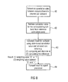
- the analyzer 16 is configured for determining (80) a correlation value between the two input channels per subband and time block, i.e. a correlation value for a time/frequency tile. Then, the analyzer 16 retrieves, in the embodiment illustrated with respect to Fig. 2 or Fig. 4 , a correlation value (82) for the corresponding subband from the reference correlation curve.
- the step 82 results in the value 41 indicating a correlation between -1 and +1, and value 41 is then the retrieved correlation value.
- step 83 the result for the subband using the determined correlation value from step 80 and the retrieved correlation value 41 obtained in step 82 is performed by performing a comparison and the subsequent decision or is done by calculating an actual difference.
- the result can be, as discussed before, a binary result saying that the actual time/frequency tile considered in the downmix/analysis signal has independent components. This decision will be taken, when the actually determined correlation value (in step 80) is equal to the reference correlation value or is quit close to the reference correlation value.
- the time/frequency tile under consideration comprises dependent components.
- the correlation of a time/frequency tile of the downmix or analysis signal indicates a higher absolute correlation value than the reference curve, then it can be said that the components in this time/frequency tile are dependent on each other.
- the correlation is indicated to be very close to the reference curve, then it can be said that the components are independent.
- Dependent components can receive a first weighting value such as 1 and independent components can receive a second weighting value such as 0.
- high and low thresholds which are spaced apart from the reference line are used in order to provide a better result which is more suited than using the reference curve alone.
- the correlation can vary between - 1 and +1.
- a correlation having a negative sign additionally indicates a phase shift of 180° between the signals. Therefore, other correlations only extending between 0 and 1 could be applied as well, in which the negative part of the correlation is simply made positive. In this procedure, one would then ignore a time shift or phase shift for the purpose of the correlation determination.
- the alternative way of calculating the result is to actually calculate the distance between the correlation value determined in block 80 and the retrieved correlation value obtained in block 82 and to then determine a metric between 0 and 1 as a weighting factor based on the distance. While the first alternative (1) in Fig. 8 only results in values of 0 or 1, the possibility (2) results in values between 0 and 1 and are, in some implementations, preferred.
- the signal processor 20 in Fig. 3 is illustrated as multipliers and the analysis results are just a determined weighting factor which is forwarded from the analyzer to the signal processor as illustrated in 84 in Fig. 8 and is then applied to the corresponding time/frequency tile of the input signal 10.
- the time/frequency tile can be indicated as (20, 5) where the first number indicates the number of the block in time and the second number indicates the frequency bin in this spectrum.
- the analysis result for time/frequency tile (20, 5) is applied to the corresponding time/frequency tile (20, 5) of each channel of the input signal in Fig. 3 or, when a signal deriver as illustrated in Fig. 1 is implemented, to the corresponding time/frequency tile of each channel of the derived signal.
- a reference curve is discussed in more detail.
- it is basically not important how the reference curve was derived. It can be an arbitrary curve or, for example, values in a look-up table indicating an ideal or desired relation of the input signals x j in the downmix signal D or, and in the context of Fig. 2 in the analysis signal.
- the following derivation is exemplary.
- r k ⁇ d sin kd kd ⁇ for three - dimensional sound fields
- r k ⁇ d J 0 kd ⁇ for two - dimensional soundfields
- d the distance between the two measurement points
- k 2 ⁇ ⁇ ⁇ is the wavenumber, with ⁇ being the wavelength.
- the physical reference curve r ( k , d ) may already be used as c ref for further processing.
- HRTFs head-related transfer functions
- the resulting pressure signals at the ear entrances are p L ( n , ⁇ ) and p R ( n, ⁇ ).
- measured HRTF data may be used or approximations can be obtained by using an analytical model (e.g. Richard O. Duda and William L. Martens, "Range dependence of the response of a spherical head model," Journal Of The Acoustical Society Of America, vol. 104, no. 5, pp. 3048-3058, November 1998 ).
- the auditory filters are assumed to behave like overlapping bandpass filters. In the following example explanation, a critical band approach is used to approximate these overlapping bandpasses by rectangular filters.
- the equivalent rectangular bandwidth (ERB) may be calculated as a function of center frequency ( Brian R. Glasberg and Brian C. J. Moore, "Derivation of auditory filter shapes from notched-noise data," Hearing Research, vol. 47, pp. 103-138, 1990 ).
- the factors 1/b (w) may or may not be used in equations (7) and (8).
- the coherence of the signals can be evaluated.
- the human auditory system is able to make use of such a time alignment property.
- the interaural coherence is calculated within ⁇ 1 ms.
- calculations can be implemented using only the lag-zero value (for low complexity) or the coherence with a time advance and delay (if high complexity is possible). In the following, no distinction is made between both cases.
- the ideal behavior is achieved considering an ideal diffuse sound field, which can be idealized as a wave field that is composed of equally strong, uncorrelated plane waves propagating in all directions (i.e. a superposition of an infinite number of propagating plane waves with random phase relations and uniformly distributed directions of propagation).
- a signal radiated by a loudspeaker can be considered a plane wave for a listener positioned sufficiently far away. This plane wave assumption is common in stereophonic playback over loudspeakers.
- a synthetic sound field reproduced by loudspeakers consists of contributing plane waves from a limited number of directions.
- Figs. 9a to 9e Different reference curves as examples for frequency-dependent reference curves or correlation curves are illustrated in Figs. 9a to 9e for a different number of sound sources at different positions of the sound sources and different head orientations as indicated in the Figs.
- the deviation of c sig ( ⁇ ) from c ref ( ⁇ ) can be calculated.
- This deviation (possibly including an upper and lower threshold) is mapped to the range [0;1] to obtain a weighting ( W ( m,i )) that is applied to all input channels to separate the independent components.
- Such a processing may be carried out in a frequency decomposition with frequency coefficients grouped to perceptually motivated subbands for reasons of computational complexity and to obtain filters with shorter impulse responses.
- smoothing filters could be applied and compression functions (i.e. distorting the weighting in a desired fashion, additionally introducing minimum and / or maximum weighting values) may be applied.
- Fig. 5 illustrates a further implementation of the present invention, in which the downmixer is implemented using HRTF and auditory filters as illustrated. Furthermore, Fig. 5 additionally illustrates that the analysis results output by the analyzer 16 are the weighting factors for each time/frequency bin, and the signal processor 20 is illustrated as an extractor for extracting independent components. Then, the output of the processor 20 is, again, N channels, but each channel now only includes the independent components and does not include any more dependent components. In this implementation, the analyzer would calculate the weightings so that, in the first implementation of Fig. 8 , an independent component would receive a weighting value of 1 and a dependent component would receive a weighting value of 0. Then, the time/frequency tiles in the original N channels processed by the processor 20 which have dependent components would be set to 0.
- the analyzer would calculate the weighting so that a time/frequency tile having a small distance to the reference curve would receive a high value (more close to 1), and a time/frequency tile having a large distance to the reference curve would receive a small weighting factor (being more close to 0).
- the independent components would, then, be amplified while the dependent components would be attenuated.
- each signal processor 20 can be applied for extracting of the signal components, since the determination of the actually extracted signal components is determined by the actual assigning of weighting values.
- Fig. 6 illustrates a further implementation of the inventive concept, but now with a different implementation of the processor 20.
- the processor 20 is implemented for extracting independent diffuse parts, independent direct parts and direct parts/components per se.
- enveloping ambience sound is equally strong from each direction.
- the minimum energy of each time-frequency tile in every channel of the independent sound signals can be extracted to obtain an enveloping ambient signal (which can be further processed to obtain a higher number of ambience channels).
- Fig. 7 depicts a variant of the general concept.
- the N-channel input signal is fed to an analysis signal generator (ASG).
- the generation of the M-channel analysis signal may e.g. include a propagation model from the channels / loudspeakers to the ears or other methods denoted as downmix throughout this document.
- the indication of the distinct components is based on the analysis signal.
- the masks indicating the different components are applied to the input signals (A extraction / D extraction (20a, 20b)).
- the weighted input signals can be further processed (A post / D post (70a, 70b) to yield output signals with specific character, where in this example the designators "A" and "D" have been chosen to indicate that the components to be extracted may be "Ambience" and "Direct Sound”.
- FIG. 10 A stationary sound fields is called diffuse, if the directional distribution of sound energy does not depend on direction.
- the directional energy distribution can be evaluated by measuring all directions using a highly directive microphone.
- the reverberant sound field in an enclosure is often modeled as a diffuse field.
- a diffuse sound field can be idealized as a wave field that is composed of equally strong, uncorrelated plane waves propagating in all directions. Such a sound field is isotropic and homogeneous.
- the point-to-point correlation coefficient r ⁇ p 1 t ⁇ p 2 t > ⁇ p 1 2 t > ⁇ ⁇ p 2 2 t > 1 2 of the steady state sound pressures p 1 (t) and p 2 (t) at two spatially separated points can be used to assess the physical diffusion of a sound field.
- the sound pressure measurements are given by the ear input signals p i (t) and p r (t).
- f kc 2 ⁇ ⁇ , where c is the speed of sound in air.
- the ear input signals differ from the previously considered free field signals due to the influence of the effects caused by the listener's pinnae, head, and torso. Those effects, substantial for spatial hearing, are described by head related transfer functions (HRTFs). Measured HRTF data may be used to incorporate these effects. We use an analytical model to simulate an approximation of the HRTFs.
- the head is modeled as a rigid sphere with radius 8.75 cm and ear locations at azimuth ⁇ 100° and elevation 0°. Given the theoretical behavior of r in an ideal diffuse sound field and the influence of the HRTFs, it is possible to determine a frequency dependent interaural cross-correlation reference curve for diffuse sound fields.
- the diffuseness estimation is based on comparison of simulated cues with assumed diffuse field reference cues. This comparison is subject to the limitations of human hearing.
- the binaural processing follows the auditory periphery consisting of the external ear, the middle ear, and the inner ear. Effects of the external ear that are not approximated by the sphere-model (e.g. pinnae-shape, ear-canal) and the effects of the middle ear are not considered.
- the spectral selectivity of the inner ear is modeled as a bank of overlapping bandpass filters (denoted auditory filters in Fig. 10 ). A critical band approach is used to approximate these overlapping bandpasses by rectangular filters.
- the human auditory system is capable of performing a time alignment to detect coherent signal components and that cross-correlation analysis is used for the estimation of the alignment time ⁇ (corresponding to ITD) in the presence of complex sounds.
- time shifts of the carrier signal are evaluated using waveform cross-correlation, while at higher frequencies the envelope cross-correlation becomes the relevant cue.
- A max ⁇ ⁇ 2 Re ⁇ ⁇ f - f + ⁇ L * f ⁇ R f ⁇ e j ⁇ 2 ⁇ ⁇ f ⁇ t - r d f
- B 2 ⁇ ⁇ f - f + ⁇ L * f ⁇ L f ⁇ e j ⁇ 2 ⁇ ⁇ ft d f
- C 2 ⁇ ⁇ f - f + ⁇ R * f ⁇ R f ⁇ e j ⁇ 2 ⁇ ⁇ ft d f
- L(f) and R(f) are the Fourier transforms of the ear input signals
- * denotes complex conjugate.
- ILD and ITD cues are evoked.
- ILD and ITD variations as a function of time and/or frequency may generate spaciousness.
- ITDs and ITDs in a diffuse sound field there must not be ILDs and ITDs in a diffuse sound field.
- An average ITD of zero means that the correlation between the signals can not be increased by time alignment.
- ILDs can in principal be evaluated over the complete audible frequency range. Because the head constitutes no obstacle at low frequencies, ILDs are most efficient at middle and high frequencies.
- FIG. 11A and 11B is discussed in order to illustrate an alternative implementation of the analyzer without using a reference curve as discussed in the context of Fig. 10 or Fig. 4 .
- a short-time Fourier transform is applied to the input surround audio channels x 1 ( n ) to x N ( n ) , yielding the short-time spectra X 1 ( m,i ) to X N ( m,i ) , respectively, where m is the spectrum (time) index and i the frequency index.
- Spectra of a stereo downmix of the surround input signal denoted X 1 ( m,i ) and X 2 ( m,i ) , are computed.
- an ITU downmix is suitable as equation (1).
- X 1 ( m,i ) to X 5 (m,i) correspond in this order to the left (L), right (R), center (C), left surround (LS), and right surround (RS) channels.
- the time and frequency indices are omitted most of the time for brevity of notation.
- filter W D and W A are computed for obtaining the direct and ambient sound surround signal estimates in equation (2) and (3).
- D 1 and D 2 represent the correlated direct sound STFT spectra, and A 1 and A 2 represent uncorrelated ambience sound.
- D 1 and D 2 represent the correlated direct sound STFT spectra
- a 1 and A 2 represent uncorrelated ambience sound.
- Estimation of the direct sound is achieved by applying a Wiener filter to the original surround signal to suppress the ambience.
- a Wiener filter to the original surround signal to suppress the ambience.
- Equation 7 The joint mean square error function for this estimation is given by equation (6).
- E ⁇ is the expectation operator and P D and P A are the sums of the short term power estimates of the direct and ambience components, (equation 7).
- estimation filter for the ambient sound can be derived as in equation 9.
- the generation of the reference curves for a minimum correlation can be imagined by placing two or more different sound sources in a replay setup and by placing a listener head at a certain position in this replay setup. Then, completely independent signals are emitted by the different loudspeakers.
- the two channels would have to be completely uncorrelated with a correlation equal to 0 in case there would not be any cross-mixing products.
- these cross-mixing products occur due to the cross-coupling from the left side to the right side of a human listening system and, other cross-couplings also occur due to room reverberations etc.. Therefore, the resulting reference curves as illustrated in Fig. 4 or in Figs.
- 9a to 9d are not always at 0, but have values particularly different from 0 although the reference signals imagined in this scenario were completely independent. It is, however important to understand that one does not actually need these signals. It is also sufficient to assume a full independence between the two or more signals when calculating the reference curve. In this context, it is to be noted, however, that other reference curves can be calculated for other scenarios, for example, using or assuming signals which are not fully independent, but have a certain, but pre-known dependency or degree of dependency between each other. When such a different reference curve is calculated, the interpretation or the providing of the weighting factors would be different with respect to a reference curve where fully independent signals were assumed.
- aspects have been described in the context of an apparatus, it is clear that these aspects also represent a description of the corresponding method, where a block or device corresponds to a method step or a feature of a method step. Analogously, aspects described in the context of a method step also represent a description of a corresponding block or item or feature of a corresponding apparatus.
- the inventive decomposed signal can be stored on a digital storage medium or can be transmitted on a transmission medium such as a wireless transmission medium or a wired transmission medium such as the Internet.
- embodiments of the invention can be implemented in hardware or in software.
- the implementation can be performed using a digital storage medium, for example a floppy disk, a DVD, a CD, a ROM, a PROM, an EPROM, an EEPROM or a FLASH memory, having electronically readable control signals stored thereon, which cooperate (or are capable of cooperating) with a programmable computer system such that the respective method is performed.
- a digital storage medium for example a floppy disk, a DVD, a CD, a ROM, a PROM, an EPROM, an EEPROM or a FLASH memory, having electronically readable control signals stored thereon, which cooperate (or are capable of cooperating) with a programmable computer system such that the respective method is performed.
- Some embodiments according to the invention comprise a non-transitory data carrier having electronically readable control signals, which are capable of cooperating with a programmable computer system, such that one of the methods described herein is performed.
- embodiments of the present invention can be implemented as a computer program product with a program code, the program code being operative for performing one of the methods when the computer program product runs on a computer.
- the program code may for example be stored on a machine readable carrier.
- inventions comprise the computer program for performing one of the methods described herein, stored on a machine readable carrier.
- an embodiment of the inventive method is, therefore, a computer program having a program code for performing one of the methods described herein, when the computer program runs on a computer.
- a further embodiment of the inventive methods is, therefore, a data carrier (or a digital storage medium, or a computer-readable medium) comprising, recorded thereon, the computer program for performing one of the methods described herein.
- a further embodiment of the inventive method is, therefore, a data stream or a sequence of signals representing the computer program for performing one of the methods described herein.
- the data stream or the sequence of signals may for example be configured to be transferred via a data communication connection, for example via the Internet.
- a further embodiment comprises a processing means, for example a computer, or a programmable logic device, configured to or adapted to perform one of the methods described herein.
- a processing means for example a computer, or a programmable logic device, configured to or adapted to perform one of the methods described herein.
- a further embodiment comprises a computer having installed thereon the computer program for performing one of the methods described herein.
- a programmable logic device for example a field programmable gate array
- a field programmable gate array may cooperate with a microprocessor in order to perform one of the methods described herein.
- the methods are preferably performed by any hardware apparatus.
Landscapes
- Engineering & Computer Science (AREA)
- Physics & Mathematics (AREA)
- Acoustics & Sound (AREA)
- Signal Processing (AREA)
- Multimedia (AREA)
- Computational Linguistics (AREA)
- Audiology, Speech & Language Pathology (AREA)
- Human Computer Interaction (AREA)
- Health & Medical Sciences (AREA)
- Spectroscopy & Molecular Physics (AREA)
- Stereophonic System (AREA)
- Measurement And Recording Of Electrical Phenomena And Electrical Characteristics Of The Living Body (AREA)
- Radar Systems Or Details Thereof (AREA)
- Amplifiers (AREA)
- Time-Division Multiplex Systems (AREA)
Priority Applications (17)
| Application Number | Priority Date | Filing Date | Title |
|---|---|---|---|
| CA2820351A CA2820351C (en) | 2010-12-10 | 2011-11-22 | Apparatus and method for decomposing an input signal using a pre-calculated reference curve |
| JP2013542451A JP5595602B2 (ja) | 2010-12-10 | 2011-11-22 | 予め計算された参照曲線を用いて入力信号を分解する装置および方法 |
| PCT/EP2011/070700 WO2012076331A1 (en) | 2010-12-10 | 2011-11-22 | Apparatus and method for decomposing an input signal using a pre-calculated reference curve |
| CN201180067248.4A CN103348703B (zh) | 2010-12-10 | 2011-11-22 | 用以利用预先算出的参考曲线来分解输入信号的装置和方法 |
| PL11793700T PL2649815T3 (pl) | 2010-12-10 | 2011-11-22 | Urządzenie i sposób do rozkładu sygnału wejściowego z użyciem wstępnie obliczonej krzywej odniesienia |
| EP11793700.3A EP2649815B1 (en) | 2010-12-10 | 2011-11-22 | Apparatus and method for decomposing an input signal using a pre-calculated reference curve |
| ES11793700.3T ES2534180T3 (es) | 2010-12-10 | 2011-11-22 | Aparato y método para descomponer una señal de entrada utilizando una curva de referencia calculada previamente |
| BR112013014173-5A BR112013014173B1 (pt) | 2010-12-10 | 2011-11-22 | Aparelho e método para decompor um sinal de entrada utilizando uma curva de referência pré-calculada |
| MX2013006364A MX2013006364A (es) | 2010-12-10 | 2011-11-22 | Aparato y metodo para descomponer una señal de entrada utilizando una curva de referencia calculada. |
| AU2011340890A AU2011340890B2 (en) | 2010-12-10 | 2011-11-22 | Apparatus and method for decomposing an input signal using a pre-calculated reference curve |
| RU2013131775/08A RU2554552C2 (ru) | 2010-12-10 | 2011-11-22 | Устройство и способ для разложения входного сигнала с использованием заранее вычисленной эталонной кривой |
| KR1020137017699A KR101480258B1 (ko) | 2010-12-10 | 2011-11-22 | 미리 계산된 참조 곡선을 이용한 입력 신호 분해 장치 및 방법 |
| TW100143542A TWI519178B (zh) | 2010-12-10 | 2011-11-28 | 用以利用預先計算參考曲線來分解輸入信號之裝置和方法 |
| ARP110104561A AR084175A1 (es) | 2010-12-10 | 2011-12-06 | Aparato y metodo para descomponer una señal de entrada utilizando una curva de referencia calculada |
| US13/911,824 US9241218B2 (en) | 2010-12-10 | 2013-06-06 | Apparatus and method for decomposing an input signal using a pre-calculated reference curve |
| HK14103528.9A HK1190552A1 (en) | 2010-12-10 | 2014-04-11 | Apparatus and method for decomposing an input signal using a pre-calculated reference curve |
| US16/209,638 US10531198B2 (en) | 2010-12-10 | 2018-12-04 | Apparatus and method for decomposing an input signal using a downmixer |
Applications Claiming Priority (1)
| Application Number | Priority Date | Filing Date | Title |
|---|---|---|---|
| US42192710P | 2010-12-10 | 2010-12-10 |
Publications (1)
| Publication Number | Publication Date |
|---|---|
| EP2464146A1 true EP2464146A1 (en) | 2012-06-13 |
Family
ID=44582056
Family Applications (4)
| Application Number | Title | Priority Date | Filing Date |
|---|---|---|---|
| EP11165742A Withdrawn EP2464145A1 (en) | 2010-12-10 | 2011-05-11 | Apparatus and method for decomposing an input signal using a downmixer |
| EP11165746A Withdrawn EP2464146A1 (en) | 2010-12-10 | 2011-05-11 | Apparatus and method for decomposing an input signal using a pre-calculated reference curve |
| EP11787858.7A Active EP2649814B1 (en) | 2010-12-10 | 2011-11-22 | Apparatus and method for decomposing an input signal using a downmixer |
| EP11793700.3A Active EP2649815B1 (en) | 2010-12-10 | 2011-11-22 | Apparatus and method for decomposing an input signal using a pre-calculated reference curve |
Family Applications Before (1)
| Application Number | Title | Priority Date | Filing Date |
|---|---|---|---|
| EP11165742A Withdrawn EP2464145A1 (en) | 2010-12-10 | 2011-05-11 | Apparatus and method for decomposing an input signal using a downmixer |
Family Applications After (2)
| Application Number | Title | Priority Date | Filing Date |
|---|---|---|---|
| EP11787858.7A Active EP2649814B1 (en) | 2010-12-10 | 2011-11-22 | Apparatus and method for decomposing an input signal using a downmixer |
| EP11793700.3A Active EP2649815B1 (en) | 2010-12-10 | 2011-11-22 | Apparatus and method for decomposing an input signal using a pre-calculated reference curve |
Country Status (16)
| Country | Link |
|---|---|
| US (3) | US10187725B2 (ru) |
| EP (4) | EP2464145A1 (ru) |
| JP (2) | JP5654692B2 (ru) |
| KR (2) | KR101480258B1 (ru) |
| CN (2) | CN103355001B (ru) |
| AR (2) | AR084176A1 (ru) |
| AU (2) | AU2011340891B2 (ru) |
| BR (2) | BR112013014172B1 (ru) |
| CA (2) | CA2820376C (ru) |
| ES (2) | ES2534180T3 (ru) |
| HK (2) | HK1190552A1 (ru) |
| MX (2) | MX2013006358A (ru) |
| PL (2) | PL2649815T3 (ru) |
| RU (2) | RU2555237C2 (ru) |
| TW (2) | TWI519178B (ru) |
| WO (2) | WO2012076332A1 (ru) |
Families Citing this family (43)
| Publication number | Priority date | Publication date | Assignee | Title |
|---|---|---|---|---|
| TWI429165B (zh) | 2011-02-01 | 2014-03-01 | Fu Da Tong Technology Co Ltd | Method of data transmission in high power induction power supply |
| US9600021B2 (en) | 2011-02-01 | 2017-03-21 | Fu Da Tong Technology Co., Ltd. | Operating clock synchronization adjusting method for induction type power supply system |
| US9831687B2 (en) | 2011-02-01 | 2017-11-28 | Fu Da Tong Technology Co., Ltd. | Supplying-end module for induction-type power supply system and signal analysis circuit therein |
| TWI472897B (zh) * | 2013-05-03 | 2015-02-11 | Fu Da Tong Technology Co Ltd | 自動調節電壓準位之方法、裝置及其感應式電源供應器 |
| US8941267B2 (en) | 2011-06-07 | 2015-01-27 | Fu Da Tong Technology Co., Ltd. | High-power induction-type power supply system and its bi-phase decoding method |
| US9048881B2 (en) | 2011-06-07 | 2015-06-02 | Fu Da Tong Technology Co., Ltd. | Method of time-synchronized data transmission in induction type power supply system |
| US9075587B2 (en) | 2012-07-03 | 2015-07-07 | Fu Da Tong Technology Co., Ltd. | Induction type power supply system with synchronous rectification control for data transmission |
| US9628147B2 (en) | 2011-02-01 | 2017-04-18 | Fu Da Tong Technology Co., Ltd. | Method of automatically adjusting determination voltage and voltage adjusting device thereof |
| US10038338B2 (en) | 2011-02-01 | 2018-07-31 | Fu Da Tong Technology Co., Ltd. | Signal modulation method and signal rectification and modulation device |
| US10056944B2 (en) | 2011-02-01 | 2018-08-21 | Fu Da Tong Technology Co., Ltd. | Data determination method for supplying-end module of induction type power supply system and related supplying-end module |
| US9671444B2 (en) | 2011-02-01 | 2017-06-06 | Fu Da Tong Technology Co., Ltd. | Current signal sensing method for supplying-end module of induction type power supply system |
| KR20120132342A (ko) * | 2011-05-25 | 2012-12-05 | 삼성전자주식회사 | 보컬 신호 제거 장치 및 방법 |
| US9253574B2 (en) * | 2011-09-13 | 2016-02-02 | Dts, Inc. | Direct-diffuse decomposition |
| BR122021021500B1 (pt) * | 2012-09-12 | 2022-10-25 | Fraunhofer-Gesellschaft zur Förderung der angewandten Forschung e. V | Aparelho e método para fornecer capacidades melhoradas de downmix guiado para áudio 3d |
| CN105210389B (zh) | 2013-03-19 | 2017-07-25 | 皇家飞利浦有限公司 | 用于确定麦克风的位置的方法和装置 |
| EP2790419A1 (en) * | 2013-04-12 | 2014-10-15 | Fraunhofer-Gesellschaft zur Förderung der angewandten Forschung e.V. | Apparatus and method for center signal scaling and stereophonic enhancement based on a signal-to-downmix ratio |
| KR102150955B1 (ko) | 2013-04-19 | 2020-09-02 | 한국전자통신연구원 | 다채널 오디오 신호 처리 장치 및 방법 |
| WO2014171791A1 (ko) | 2013-04-19 | 2014-10-23 | 한국전자통신연구원 | 다채널 오디오 신호 처리 장치 및 방법 |
| US20140355769A1 (en) * | 2013-05-29 | 2014-12-04 | Qualcomm Incorporated | Energy preservation for decomposed representations of a sound field |
| US9319819B2 (en) * | 2013-07-25 | 2016-04-19 | Etri | Binaural rendering method and apparatus for decoding multi channel audio |
| JP6121052B2 (ja) | 2013-09-17 | 2017-04-26 | ウィルス インスティテュート オブ スタンダーズ アンド テクノロジー インコーポレイティド | マルチメディア信号処理方法および装置 |
| CN108449704B (zh) | 2013-10-22 | 2021-01-01 | 韩国电子通信研究院 | 生成用于音频信号的滤波器的方法及其参数化装置 |
| EP3934283B1 (en) | 2013-12-23 | 2023-08-23 | Wilus Institute of Standards and Technology Inc. | Audio signal processing method and parameterization device for same |
| RU2747713C2 (ru) | 2014-01-03 | 2021-05-13 | Долби Лабораторис Лайсэнзин Корпорейшн | Генерирование бинаурального звукового сигнала в ответ на многоканальный звуковой сигнал с использованием по меньшей мере одной схемы задержки с обратной связью |
| CN104768121A (zh) | 2014-01-03 | 2015-07-08 | 杜比实验室特许公司 | 响应于多通道音频通过使用至少一个反馈延迟网络产生双耳音频 |
| KR101782917B1 (ko) | 2014-03-19 | 2017-09-28 | 주식회사 윌러스표준기술연구소 | 오디오 신호 처리 방법 및 장치 |
| EP3128766A4 (en) | 2014-04-02 | 2018-01-03 | Wilus Institute of Standards and Technology Inc. | Audio signal processing method and device |
| EP2942982A1 (en) * | 2014-05-05 | 2015-11-11 | Fraunhofer-Gesellschaft zur Förderung der angewandten Forschung e.V. | System, apparatus and method for consistent acoustic scene reproduction based on informed spatial filtering |
| EP3165007B1 (en) | 2014-07-03 | 2018-04-25 | Dolby Laboratories Licensing Corporation | Auxiliary augmentation of soundfields |
| CN105336332A (zh) * | 2014-07-17 | 2016-02-17 | 杜比实验室特许公司 | 分解音频信号 |
| EP3197182B1 (en) * | 2014-08-13 | 2020-09-30 | Samsung Electronics Co., Ltd. | Method and device for generating and playing back audio signal |
| US9666192B2 (en) | 2015-05-26 | 2017-05-30 | Nuance Communications, Inc. | Methods and apparatus for reducing latency in speech recognition applications |
| US10559303B2 (en) * | 2015-05-26 | 2020-02-11 | Nuance Communications, Inc. | Methods and apparatus for reducing latency in speech recognition applications |
| TWI596953B (zh) * | 2016-02-02 | 2017-08-21 | 美律實業股份有限公司 | 錄音模組 |
| WO2017157427A1 (en) * | 2016-03-16 | 2017-09-21 | Huawei Technologies Co., Ltd. | An audio signal processing apparatus and method for processing an input audio signal |
| EP3232688A1 (en) * | 2016-04-12 | 2017-10-18 | Fraunhofer-Gesellschaft zur Förderung der angewandten Forschung e.V. | Apparatus and method for providing individual sound zones |
| US10187740B2 (en) * | 2016-09-23 | 2019-01-22 | Apple Inc. | Producing headphone driver signals in a digital audio signal processing binaural rendering environment |
| US10659904B2 (en) * | 2016-09-23 | 2020-05-19 | Gaudio Lab, Inc. | Method and device for processing binaural audio signal |
| JP6788272B2 (ja) * | 2017-02-21 | 2020-11-25 | オンフューチャー株式会社 | 音源の検出方法及びその検出装置 |
| CN110383700A (zh) * | 2017-03-10 | 2019-10-25 | 英特尔Ip公司 | 杂散降低电路和装置、无线电收发器、移动终端、用于杂散降低的方法和计算机程序 |
| IT201700040732A1 (it) * | 2017-04-12 | 2018-10-12 | Inst Rundfunktechnik Gmbh | Verfahren und vorrichtung zum mischen von n informationssignalen |
| ES2907377T3 (es) | 2017-10-04 | 2022-04-25 | Fraunhofer Ges Forschung | Aparato, procedimiento y programa informático para la codificación, la decodificación, el procesamiento de escenas y otros procedimientos relacionados con la codificación de audio espacial basada en DirAC |
| CN111107481B (zh) | 2018-10-26 | 2021-06-22 | 华为技术有限公司 | 一种音频渲染方法及装置 |
Citations (7)
| Publication number | Priority date | Publication date | Assignee | Title |
|---|---|---|---|---|
| US5065759A (en) * | 1990-08-30 | 1991-11-19 | Vitatron Medical B.V. | Pacemaker with optimized rate responsiveness and method of rate control |
| US20080120123A1 (en) * | 2006-11-21 | 2008-05-22 | Yahoo! Inc. | Method and system for finding similar charts for financial analysis |
| US20080240338A1 (en) * | 2007-03-26 | 2008-10-02 | Siemens Aktiengesellschaft | Evaluation method for mapping the myocardium of a patient |
| US7563975B2 (en) * | 2005-09-14 | 2009-07-21 | Mattel, Inc. | Music production system |
| WO2009100876A1 (de) * | 2008-02-14 | 2009-08-20 | Fraunhofer-Gesellschaft zur Förderung der angewandten Forschung e.V. | Vorrichtung und verfahren zum synchronisieren von mehrkanalerweiterungsdaten mit einem audiosignal und zum verarbeiten des audiosignals |
| US20090252341A1 (en) * | 2006-05-17 | 2009-10-08 | Creative Technology Ltd | Adaptive Primary-Ambient Decomposition of Audio Signals |
| WO2010125228A1 (en) * | 2009-04-30 | 2010-11-04 | Nokia Corporation | Encoding of multiview audio signals |
Family Cites Families (26)
| Publication number | Priority date | Publication date | Assignee | Title |
|---|---|---|---|---|
| US9025A (en) * | 1852-06-15 | And chas | ||
| US7026A (en) * | 1850-01-15 | Door-lock | ||
| US5912976A (en) * | 1996-11-07 | 1999-06-15 | Srs Labs, Inc. | Multi-channel audio enhancement system for use in recording and playback and methods for providing same |
| TW358925B (en) * | 1997-12-31 | 1999-05-21 | Ind Tech Res Inst | Improvement of oscillation encoding of a low bit rate sine conversion language encoder |
| SE514862C2 (sv) | 1999-02-24 | 2001-05-07 | Akzo Nobel Nv | Användning av en kvartär ammoniumglykosidtensid som en effektförhöjande hjälpkemikalie för gödningsmedel eller pesticider samt kompositioner innehållande pesticider eller gödningsmedel |
| US6694027B1 (en) * | 1999-03-09 | 2004-02-17 | Smart Devices, Inc. | Discrete multi-channel/5-2-5 matrix system |
| CN100539742C (zh) * | 2002-07-12 | 2009-09-09 | 皇家飞利浦电子股份有限公司 | 多声道音频信号编解码方法和装置 |
| RU2315371C2 (ru) * | 2002-12-28 | 2008-01-20 | Самсунг Электроникс Ко., Лтд. | Способ и устройство для смешивания аудиопотока и носитель информации |
| US7254500B2 (en) | 2003-03-31 | 2007-08-07 | The Salk Institute For Biological Studies | Monitoring and representing complex signals |
| JP2004354589A (ja) * | 2003-05-28 | 2004-12-16 | Nippon Telegr & Teleph Corp <Ntt> | 音響信号判別方法、音響信号判別装置、音響信号判別プログラム |
| AU2005219956B2 (en) * | 2004-03-01 | 2009-05-28 | Dolby Laboratories Licensing Corporation | Multichannel audio coding |
| WO2005086138A1 (ja) * | 2004-03-05 | 2005-09-15 | Matsushita Electric Industrial Co., Ltd. | エラー隠蔽装置およびエラー隠蔽方法 |
| US7272567B2 (en) * | 2004-03-25 | 2007-09-18 | Zoran Fejzo | Scalable lossless audio codec and authoring tool |
| US8843378B2 (en) * | 2004-06-30 | 2014-09-23 | Fraunhofer-Gesellschaft Zur Foerderung Der Angewandten Forschung E.V. | Multi-channel synthesizer and method for generating a multi-channel output signal |
| PL1810280T3 (pl) * | 2004-10-28 | 2018-01-31 | Dts Inc | Silnik przestrzennego środowiska dźwiękowego |
| US7961890B2 (en) * | 2005-04-15 | 2011-06-14 | Fraunhofer-Gesellschaft Zur Foerderung Der Angewandten Forschung, E.V. | Multi-channel hierarchical audio coding with compact side information |
| US7468763B2 (en) * | 2005-08-09 | 2008-12-23 | Texas Instruments Incorporated | Method and apparatus for digital MTS receiver |
| KR100739798B1 (ko) * | 2005-12-22 | 2007-07-13 | 삼성전자주식회사 | 청취 위치를 고려한 2채널 입체음향 재생 방법 및 장치 |
| SG136836A1 (en) * | 2006-04-28 | 2007-11-29 | St Microelectronics Asia | Adaptive rate control algorithm for low complexity aac encoding |
| US8379868B2 (en) * | 2006-05-17 | 2013-02-19 | Creative Technology Ltd | Spatial audio coding based on universal spatial cues |
| US8023660B2 (en) | 2008-09-11 | 2011-09-20 | Fraunhofer-Gesellschaft Zur Foerderung Der Angewandten Forschung E.V. | Apparatus, method and computer program for providing a set of spatial cues on the basis of a microphone signal and apparatus for providing a two-channel audio signal and a set of spatial cues |
| JP5845090B2 (ja) * | 2009-02-09 | 2016-01-20 | ウェーブス・オーディオ・リミテッド | 複数マイクロフォンベースの方向性音フィルタ |
| KR101566967B1 (ko) * | 2009-09-10 | 2015-11-06 | 삼성전자주식회사 | 디지털 방송 시스템에서 패킷 디코딩 방법 및 장치 |
| EP2323130A1 (en) * | 2009-11-12 | 2011-05-18 | Koninklijke Philips Electronics N.V. | Parametric encoding and decoding |
| US20130070927A1 (en) | 2010-06-02 | 2013-03-21 | Koninklijke Philips Electronics N.V. | System and method for sound processing |
| US9183849B2 (en) | 2012-12-21 | 2015-11-10 | The Nielsen Company (Us), Llc | Audio matching with semantic audio recognition and report generation |
-
2011
- 2011-05-11 EP EP11165742A patent/EP2464145A1/en not_active Withdrawn
- 2011-05-11 EP EP11165746A patent/EP2464146A1/en not_active Withdrawn
- 2011-11-22 CA CA2820376A patent/CA2820376C/en active Active
- 2011-11-22 BR BR112013014172-7A patent/BR112013014172B1/pt active IP Right Grant
- 2011-11-22 CN CN201180067280.2A patent/CN103355001B/zh active Active
- 2011-11-22 KR KR1020137017699A patent/KR101480258B1/ko active IP Right Grant
- 2011-11-22 ES ES11793700.3T patent/ES2534180T3/es active Active
- 2011-11-22 JP JP2013542452A patent/JP5654692B2/ja active Active
- 2011-11-22 EP EP11787858.7A patent/EP2649814B1/en active Active
- 2011-11-22 JP JP2013542451A patent/JP5595602B2/ja active Active
- 2011-11-22 WO PCT/EP2011/070702 patent/WO2012076332A1/en active Application Filing
- 2011-11-22 MX MX2013006358A patent/MX2013006358A/es active IP Right Grant
- 2011-11-22 PL PL11793700T patent/PL2649815T3/pl unknown
- 2011-11-22 PL PL11787858T patent/PL2649814T3/pl unknown
- 2011-11-22 AU AU2011340891A patent/AU2011340891B2/en active Active
- 2011-11-22 KR KR1020137017810A patent/KR101471798B1/ko active IP Right Grant
- 2011-11-22 RU RU2013131774/08A patent/RU2555237C2/ru active
- 2011-11-22 CN CN201180067248.4A patent/CN103348703B/zh active Active
- 2011-11-22 WO PCT/EP2011/070700 patent/WO2012076331A1/en active Application Filing
- 2011-11-22 AU AU2011340890A patent/AU2011340890B2/en active Active
- 2011-11-22 BR BR112013014173-5A patent/BR112013014173B1/pt active IP Right Grant
- 2011-11-22 RU RU2013131775/08A patent/RU2554552C2/ru active
- 2011-11-22 MX MX2013006364A patent/MX2013006364A/es active IP Right Grant
- 2011-11-22 EP EP11793700.3A patent/EP2649815B1/en active Active
- 2011-11-22 CA CA2820351A patent/CA2820351C/en active Active
- 2011-11-22 ES ES11787858T patent/ES2530960T3/es active Active
- 2011-11-28 TW TW100143542A patent/TWI519178B/zh active
- 2011-11-28 TW TW100143541A patent/TWI524786B/zh active
- 2011-12-06 AR ARP110104562A patent/AR084176A1/es active IP Right Grant
- 2011-12-06 AR ARP110104561A patent/AR084175A1/es active IP Right Grant
-
2013
- 2013-06-06 US US13/911,791 patent/US10187725B2/en active Active
- 2013-06-06 US US13/911,824 patent/US9241218B2/en active Active
-
2014
- 2014-04-11 HK HK14103528.9A patent/HK1190552A1/xx unknown
- 2014-04-16 HK HK14103633.1A patent/HK1190553A1/xx unknown
-
2018
- 2018-12-04 US US16/209,638 patent/US10531198B2/en active Active
Patent Citations (7)
| Publication number | Priority date | Publication date | Assignee | Title |
|---|---|---|---|---|
| US5065759A (en) * | 1990-08-30 | 1991-11-19 | Vitatron Medical B.V. | Pacemaker with optimized rate responsiveness and method of rate control |
| US7563975B2 (en) * | 2005-09-14 | 2009-07-21 | Mattel, Inc. | Music production system |
| US20090252341A1 (en) * | 2006-05-17 | 2009-10-08 | Creative Technology Ltd | Adaptive Primary-Ambient Decomposition of Audio Signals |
| US20080120123A1 (en) * | 2006-11-21 | 2008-05-22 | Yahoo! Inc. | Method and system for finding similar charts for financial analysis |
| US20080240338A1 (en) * | 2007-03-26 | 2008-10-02 | Siemens Aktiengesellschaft | Evaluation method for mapping the myocardium of a patient |
| WO2009100876A1 (de) * | 2008-02-14 | 2009-08-20 | Fraunhofer-Gesellschaft zur Förderung der angewandten Forschung e.V. | Vorrichtung und verfahren zum synchronisieren von mehrkanalerweiterungsdaten mit einem audiosignal und zum verarbeiten des audiosignals |
| WO2010125228A1 (en) * | 2009-04-30 | 2010-11-04 | Nokia Corporation | Encoding of multiview audio signals |
Non-Patent Citations (13)
| Title |
|---|
| BOAZ RAFAELY: "Spatially Optimal Wiener Filtering in a Reverberant Sound Field", IEEE WORKSHOP ON APPLICATIONS OF SIGNAL PROCESSING TO AUDIO AND ACOUSTICS 2001, 21 October 2001 (2001-10-21) |
| BRIAN R. GLASBERG, BRIAN C. J. MOORE: "Derivation of auditory filter shapes from notched-noise data", HEARING RESEARCH, vol. 47, 1990, pages 103 - 138 |
| C. AVENDANO, J.-M. JOT: "A frequency-domain approach to multichannel upmix", JOURNAL OF THE AUDIO ENGINEERING SOCIETY, vol. 52, no. 7/8, 2004, pages 740 - 749 |
| C. FALLER: "A highly directive 2-capsule based microphone system", PREPRINT 123RD CONV. AUD. ENG. SOC., October 2007 (2007-10-01) |
| CARLOS AVENDANO, JEAN-MARC JOT: "A frequency-domain approach to multichannel upmix", JOURNAL OF THE AUDIO ENGINEERING SOCIETY, vol. 52, no. 7/8, 2004, pages 740 - 749 |
| CHRISTOF FALLER: "Multiple-loudspeaker playback of stereo signals", JOURNAL OF THE AUDIO ENGINEERING SOCIETY, vol. 54, no. 11, November 2006 (2006-11-01), pages 1051 - 1064 |
| JOHN USHERAND, JACOB BENESTY: "Enhancement of spatial sound quality: A new reverberation-extraction audio upmixer", IEEE TRANSACTIONS ON AUDIO, SPEECH, AND LANGUAGE PROCESSING, vol. 15, no. 7, September 2007 (2007-09-01), pages 2141 - 2150 |
| JUHA MERIMAA, VILLE PULKKI: "Spatial impulse response rendering", PROC. OF THE 7`H INT. CONF ON DIGITAL AUDIO EFFECTS (DAFX'04, 2004 |
| JULIA JAKKA: "Ph.D. thesis, Master's Thesis", 2005, HELSINKI UNIVERSITY OF TECHNOLOGY, article "Binaural to Multichannel Audio Upmix" |
| M. M. GOODWIN, J. M. JOT: "Primary-ambient signal decomposition and vector-based localization for spatial audio coding and enhancement", PROC. OF ICASSP 2007, 2007 |
| RICHARD K. COOK, R. V. WATERHOUSE, R. D. BERENDT, SEYMOUR EDELMAN, JR. M.C. THOMPSON: "Measurement of correlation coefficients in reverberant sound fields", JOURNAL OF THE ACOUSTICAL SOCIETY OF AMERICA, vol. 27, no. 6, November 1955 (1955-11-01), pages 1072 - 1077 |
| RICHARD O. DUDA, WILLIAM L. MARTENS: "Range dependence of the response of a spherical head model", JOURNAL OF THE ACOUSTICAL SOCIETY OF AMERICA, vol. 104, no. 5, November 1998 (1998-11-01), pages 3048 - 3058 |
| VILLE PULKKI: "Spatial sound reproduction with directional audio coding", JOURNAL OF THE AUDIO ENGINEERING SOCIETY, vol. 55, no. 6, June 2007 (2007-06-01), pages 503 - 516 |
Also Published As
Similar Documents
| Publication | Publication Date | Title |
|---|---|---|
| US10531198B2 (en) | Apparatus and method for decomposing an input signal using a downmixer | |
| US9729991B2 (en) | Apparatus and method for generating an output signal employing a decomposer | |
| AU2015255287B2 (en) | Apparatus and method for generating an output signal employing a decomposer |
Legal Events
| Date | Code | Title | Description |
|---|---|---|---|
| PUAI | Public reference made under article 153(3) epc to a published international application that has entered the european phase |
Free format text: ORIGINAL CODE: 0009012 |
|
| AK | Designated contracting states |
Kind code of ref document: A1 Designated state(s): AL AT BE BG CH CY CZ DE DK EE ES FI FR GB GR HR HU IE IS IT LI LT LU LV MC MK MT NL NO PL PT RO RS SE SI SK SM TR |
|
| AX | Request for extension of the european patent |
Extension state: BA ME |
|
| STAA | Information on the status of an ep patent application or granted ep patent |
Free format text: STATUS: THE APPLICATION IS DEEMED TO BE WITHDRAWN |
|
| 18D | Application deemed to be withdrawn |
Effective date: 20121214 |