EP2463802A2 - Optische Codeerkennungsvorrichtung - Google Patents
Optische Codeerkennungsvorrichtung Download PDFInfo
- Publication number
- EP2463802A2 EP2463802A2 EP11187466A EP11187466A EP2463802A2 EP 2463802 A2 EP2463802 A2 EP 2463802A2 EP 11187466 A EP11187466 A EP 11187466A EP 11187466 A EP11187466 A EP 11187466A EP 2463802 A2 EP2463802 A2 EP 2463802A2
- Authority
- EP
- European Patent Office
- Prior art keywords
- scanner
- scanning station
- optical code
- imaging scanner
- imaging
- Prior art date
- Legal status (The legal status is an assumption and is not a legal conclusion. Google has not performed a legal analysis and makes no representation as to the accuracy of the status listed.)
- Granted
Links
Images


Classifications
-
- G—PHYSICS
- G07—CHECKING-DEVICES
- G07G—REGISTERING THE RECEIPT OF CASH, VALUABLES, OR TOKENS
- G07G1/00—Cash registers
- G07G1/0036—Checkout procedures
- G07G1/0045—Checkout procedures with a code reader for reading of an identifying code of the article to be registered, e.g. barcode reader or radio-frequency identity [RFID] reader
-
- G—PHYSICS
- G06—COMPUTING OR CALCULATING; COUNTING
- G06K—GRAPHICAL DATA READING; PRESENTATION OF DATA; RECORD CARRIERS; HANDLING RECORD CARRIERS
- G06K7/00—Methods or arrangements for sensing record carriers, e.g. for reading patterns
- G06K7/10—Methods or arrangements for sensing record carriers, e.g. for reading patterns by electromagnetic radiation, e.g. optical sensing; by corpuscular radiation
- G06K7/10544—Methods or arrangements for sensing record carriers, e.g. for reading patterns by electromagnetic radiation, e.g. optical sensing; by corpuscular radiation by scanning of the records by radiation in the optical part of the electromagnetic spectrum
- G06K7/10821—Methods or arrangements for sensing record carriers, e.g. for reading patterns by electromagnetic radiation, e.g. optical sensing; by corpuscular radiation by scanning of the records by radiation in the optical part of the electromagnetic spectrum further details of bar or optical code scanning devices
- G06K7/10881—Methods or arrangements for sensing record carriers, e.g. for reading patterns by electromagnetic radiation, e.g. optical sensing; by corpuscular radiation by scanning of the records by radiation in the optical part of the electromagnetic spectrum further details of bar or optical code scanning devices constructional details of hand-held scanners
-
- G—PHYSICS
- G06—COMPUTING OR CALCULATING; COUNTING
- G06Q—INFORMATION AND COMMUNICATION TECHNOLOGY [ICT] SPECIALLY ADAPTED FOR ADMINISTRATIVE, COMMERCIAL, FINANCIAL, MANAGERIAL OR SUPERVISORY PURPOSES; SYSTEMS OR METHODS SPECIALLY ADAPTED FOR ADMINISTRATIVE, COMMERCIAL, FINANCIAL, MANAGERIAL OR SUPERVISORY PURPOSES, NOT OTHERWISE PROVIDED FOR
- G06Q30/00—Commerce
- G06Q30/06—Buying, selling or leasing transactions
Definitions
- This invention relates an optical code recognition apparatus. More particularly, but not exclusively, it relates to an optical code recognition apparatus comprising a fixed optical code scanner and an imaging scanner operable in both hand held and fixed configurations.
- Checkout terminals use stationary barcode scanners, which can be mono-optic, a single scanner typically mounted in the horizontal direction, or bi-optic, typically mutually orthogonal scanners mounted in the horizontal and vertical directions respectively.
- imaging scanners are useful for the reading of two-dimensional barcodes and where a smaller than standard barcode is applied to an item. Imaging scanners are also useful where product recognition of non-barcoded items, for example fruit and vegetables, is required and also where barcodes cannot be scanned, for example where the barcode applied to an item is damaged, an image of the barcode can be analysed. Also, image capture can be used for imaging cheques and for security to prevent theft.
- ergonomic efficiency of the imaging scanners leads to greater throughput of items through the retail checkout leading to shorter customer queuing times and greater customer satisfaction. Also, ergonomic design leads to reduced operator fatigue and fewer operator injuries, for example repetitive strain injuries.
- a reduction in the footprint of the scanning portion of the retail checkout leads to a reduced footprint of the overall retail checkout which is clearly desirable for retailers where floorspace is at a premium.
- Handheld barcode scanners suffer from the problem that they are configured only for handheld scanning and cannot be readily integrated with stationary barcode scanners to compliment their operation as the optical path required for handheld use is fundamentally different from that required to operate in conjunction with stationary barcode scanners. Furthermore, handheld barcode scanners are typically constrained by cabling reducing the freedom of movement of checkout staff who use them.
- an optical code scanning station comprising:
- the detachable imaging scanner may comprise:
- the receiving portion may be arranged to retain the imaging scanner such that the image capture device of the imaging scanner is directed towards a scan volume of the fixed optical code scanner.
- the imaging scanner may comprise a wireless transceiver.
- the wireless transceiver may utilise any one of the following data transmission techniques: Bluetooth, RF, WIFI, Infra-red.
- the imaging scanner may comprise a rechargeable power source.
- the imaging scanner may comprise a charging connector arranged to receive power from a complimentary charging connector of the receiving portion and is further arranged to supply this power to the rechargeable power supply.
- the imaging scanner may be arranged to communicate with the scanning station wirelessly when detached therefrom.
- the imaging scanner may be arranged to operate wirelessly or wired of the scanning station when attached thereto.
- the fixed optical code scanner may comprise:
- the fixed optical code scanner may comprise a laser scanner.
- the scan window may be aligned horizontally.
- the receiving portion may be formed in an edge of the housing.
- the receiving portion may be recessed into the edge such that only a portion of the imaging scanner projects beyond the level of the scan window, when received therein.
- the longitudinal axis of the imaging scanner, when received in the receiving portion may be parallel to the direction of travel of an object passing over the scan window.
- the longitudinal axis of the imaging scanner, when received in the receiving portion may be parallel to the direction of travel of a belt drive associated with the fixed optical code scanner.
- the scan window of the fixed optical code scanner may be aligned vertically.
- the receiving portion may be formed in an upper surface of the housing.
- the receiving portion may be arranged to receive the imaging scanner such that the image capture device is remote from the housing.
- the longitudinal axis of the imaging scanner, when received in the receiving portion may be perpendicular to the direction of travel of an object passing over the scan window.
- the longitudinal axis of the imaging scanner, when received in the receiving portion may be perpendicular to the direction of travel of a belt drive associated with the fixed optical code scanner.
- the scanning station may comprise two mutually orthogonally oriented fixed optical code scanners.
- the receiving portion may be located in either of the fixed optical code scanners.
- a detachable imaging scanner for use with a retail checkout terminal comprising:
- the imaging scanner may be arranged to be received in a receiving portion of a fixed scanning station.
- the receiving portion may be arranged to retain the imaging scanner such that the window of the imaging scanner is directed towards a scan volume of a fixed optical code scanner of the scanning station.
- the imaging scanner may comprise a wireless transceiver.
- the wireless transceiver may be arranged to communicate with a complimentary wireless transceiver of a fixed scanning station.
- the wireless transceiver may utilise any one of the following data transmission techniques: Bluetooth, RF, WIFI, or Infra-red.
- the imaging scanner may comprise a rechargeable power source.
- the imaging scanner may comprise a charging connector arranged to receive power from a complimentary charging connector of a receiving portion of a scanning station.
- the imaging scanner may be arranged to communicate with the scanning station wirelessly wired when detached therefrom.
- the imaging scanner may be arranged to be operated wirelessly or wired when attached to a scanning station.
- an optical code recognition apparatus comprising:
- a method of operating a retail checkout terminal comprising receiving a detachable imaging scanner in a receiving portion adjacent a fixed optical code scanner of the retail checkout terminal.
- the method may comprise defining a field of view of an image capture device of the imaging scanner via a window of the imaging scanner.
- the method may comprise directing the window of the imaging scanner towards a scan volume of the fixed optical code scanner.
- the method may comprise communicating between the imaging scanner and the retail checkout terminal wirelessly, at least some of the time.
- the method may comprise utilising any of the following data transmission techniques: Bluetooth, RF, WIFI or Infra-red.
- the method may comprise operating the imaging scanner wirelessly when detached from the retail checkout terminal.
- the method may comprise charging a rechargeable power supply of the imaging scanner from a charging connector of the receiving portion.
- the method may comprise:
- the method may comprise receiving imaging scanner in the receiving portion such that only a portion of the imaging scanner projects beyond the level of the scan window, when received in the receiving portion.
- the method may comprise aligning a longitudinal axis of the imaging scanner parallel to the direction of travel of an object passing over the scan window, when received in the receiving portion.
- the method may comprise aligning a longitudinal axis of the imaging scanner parallel to the direction of travel of a belt drive associated with the fixed barcode scanner, when received in the receiving portion.
- the method may comprise receiving the imaging scanner in the receiving portion such that the image capture device is remote from the housing.
- the method may comprise aligning a longitudinal axis of the imaging scanner perpendicular to the direction of travel of an obj ect passing over the scan window, when received in the receiving portion.
- the method may comprise aligning a longitudinal axis of the imaging scanner perpendicular to the direction of travel of a belt drive associated with the fixed optical code scanner, when received in the receiving portion.
- the retail checkout terminal may comprise two mutually orthogonally oriented fixed optical code scanners.
- the method may comprise associating the imaging scanner with one of the fixed optical code scanners.
- a scanning terminal to identify an optical code presented to the terminal, the method comprising:
- the method may comprise capturing the image data when the imaging scanner is detached from the scanning terminal.
- the method may comprise capturing the image data when the imaging scanner is attached to the scanning terminal.
- the processor may be located within the imaging scanner.
- the fixed scanner may comprise a laser scanner.
- Receiving the image data may comprise using wireless communications.
- the method may comprise directing an image of the optical code to the imaging scanner by an optical device in the scanning terminal.
- the method may comprise defining a field of view for the scanning terminal and using an optical device in the scanning terminal directing an image from the field of view to the imaging scanner when the imaging scanner is attached.
- the method may comprise receiving the scan data at the fixed scanner from the field of view through a first optical window in the scanning terminal and the imaging scanner receives image data directed from the first optical window.
- the method may comprise receiving scan data at the fixed scanner through a second optical window in the scanning terminal.
- the method may comprise defining a field of view for the imaging scanner, where the imaging scanner is detached, that does not coincide with the field of view for the scanning terminal.
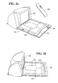
- a retail checkout terminal 100 comprises a belt 102, a scanning station 104 and a bagging area 106.
- the belt 102 drives customer's purchases towards the scanning station 104 so that optical codes on the purchased items can be scanned to form a transaction list and an associated bill. Once the purchased items have been scanned the customer places they are moved into the bagging area 106 for placement into bags for removal.
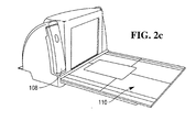
- the scanning station 104 comprises a detachable image scanner 108 and a fixed barcode scanner 110.
- the detachable image scanner 108 is operable in either a hand held configuration, hereinafter referred to as a first configuration, and a fixed configuration where the image scanner 108 is received in the scanning station 104, hereinafter referred to as a second configuration.
- the imaging scanner 108 comprises an elongate housing 112, an image capture device 114, typically a CMOS imaging array, a processor 116, a rechargeable power supply 120, typically a battery, a charging connector 122 and a wireless transceiver 124, typically utilising WiFi, RF, Infra-red or Bluetooth.
- the housing 112 comprises an imaging window 126 passing through it such that the window 126 defines a field of view of the image capture device 114.
- the scanning fixed barcode scanner 110 comprises a bi-optic barcode scanner, the construction and operation of a bi-optic barcode scanner is described in US patent number 5,229,588 .
- the bi-optic scanner 110 of the present embodiment comprises a vertical window 128 and a horizontal window 129, each of which define a scan volume of the bi-optic scanner 110, within which an barcode on an object can be scanned.
- the horizontal window 129 and its surround 129a comprise a weighing scale for weighing, for example, fresh produce and other items sold on a "by weight" basis.
- the barcode scanner 110 comprises a receiving cradle 130 adjacent the horizontal window 129 into which the imaging scanner 108 sits.
- the receiving cradle 130 comprises a scalloped recess 132 in an edge of the barcode scanner 110 opposite the vertical window 128.
- the cradle 130 retains the imaging scanner 108 in the second configuration such that the imaging scanner 108 lies parallel to the direction of travel of items through the scanning station 104.
- the cradle 130 retains the imaging scanner 108 such that a portion of the housing 112 lies below the level of the horizontal window 129 whilst the imaging window 126 has a field of view which includes at least part of the scan volume of the bi-optic scanner 110.
- the receiving cradle 130 comprises a charging connector 134 which is complimentary to the charging connector 122 of the imaging scanner 108.
- the rechargeable power supply 120 of the imaging scanner 108 draws power from a power supply of the scanning station 104 to recharges the power supply 120 when the imaging scanner 108 is retained in the receiving cradle 130.
- the imaging scanner 108 When used in the first configuration, the imaging scanner 108 is removed from the cradle 130, held in the user's hand and images of barcodes, or other optical codes, or of produce, in the case of produce recognition, or images of driver's licenses or checks in the field are captured by the image capture device 114.
- data corresponding to an image captured by the image capture device 114 is passed to the processor 116 and then on to the wireless transceiver 122.
- the wireless transceiver 122 transmits the data to a remote station, typically a wireless transceiver in the scanning station 104, where it is processed to extract information from the image data.
- the information extracted from the image data may comprise, but is not limited to, barcode information or two dimensional barcode information which identifies a product associated with the barcode.
- the information extracted may be produce recognition data, for example identifying an item of fresh produce such as a banana or a melon by shape, colour, a company logo etc.
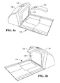
- a second embodiment of the scanning station 104 comprises a detachable image scanner 136 and a fixed barcode scanner 138.
- the detachable image scanner 136 is substantially as described hereinbefore in relation to Figure 3 and similar parts will be accorded the same reference numeral.
- the fixed barcode scanner 138 is a bi-optic barcode scanner substantially as described hereinbefore in relation to Figures 2a and 2b and similar parts will be accorded the same reference numeral.
- a vertical optics housing 140 of the bi-optic barcode scanner 138 comprises the vertical window 128.
- the optics housing 140 comprises a recessed channel 142 in an upper edge thereof.
- the channel 142 is located at approximately the midpoint of the vertical window 128 and is dimensioned to retain the imaging scanner 136 such that the field of view of the image capture device 114 of the imaging scanner 136 encompasses at least part of the scan volume of the bi-optic scanner 138.
- the longitudinal axis of the imaging scanner is perpendicular to the direction of travel of items through the scanning station 104.
- the channel 142 frictionally engags with the housing of the imaging scanner 136 to retain it in position.
- the channel 142 and housing of the imaging scanner 136 can comprise complementary elements of fixing arrangements, for example discrete recesses and projections, or tongue and groove, to retain the imaging scanner 136 in position.
- a recharging connector in the channel 142 is similar to that described in relation to Figures 2a, 2b , and 3 , such that charging of the imaging scanner 136 is effected when the imaging scanner 136 is located in the channel 142.
- the recharging connector of the imaging scanner 136 of the present embodiment will be located at an end of the housing remote from the imaging window.
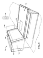
- the scanning station 104 comprises a detachable image scanner 144 and a fixed barcode scanner 146.
- the detachable image scanner 144 is substantially as described hereinbefore in relation to Figure 3 and similar parts will be accorded the same reference numeral.
- the fixed barcode scanner 146 is a bi-optic barcode scanner substantially as described hereinbefore in relation to Figures 2a and 2b and similar parts will be accorded the same reference numeral.
- a vertical optics tower 148 of the barcode scanner 146 comprises a housing 150, the vertical window 128 and optics 152 internal of the housing.
- the optics 152 comprise pattern mirrors 154, 156, 158 and imaging mirror 160.
- the housing 150 comprises a rear wall 162 opposite the vertical window 128 and respective side walls 164, 166 which extend from the rear wall 162 to meet a face containing the vertical window 128 and an external receiving cradle 168 adjacent the window 128 which is arranged to receive the imaging scanner 144.
- the side pattern mirrors 154, 156 are mounted on respective side walls 164, 166 of the housing 150.
- the rear pattern mirror 158 is mounted on the rear wall 162 of the housing 150.
- the pattern mirrors 154, 156, 158 act to direct light from a light source of the barcode scanner 146 through the vertical window 128 into the scan volume of the barcode scanner 146.
- the imaging mirror 160 is positioned below the rear pattern mirror 158, out of the path of light from the light source and is directed towards the scan volume of the barcode scanner 146.
- a window 170 passes through the housing adj acent the cradle 168 such that there is a line of sight between the window 170 and the imaging mirror 160, typically, but not essentially, this line of sight passes between the side pattern mirror 156 and the rear pattern mirror 158.
- the cradle 168 receives the imaging scanner 144 such that the imaging window 126 of the imaging scanner 108 has a field of view which includes the vertical window 128.
- the orientation of the imaging scanner 144 in the cradle 168 is such that the field of view of the imaging scanner 144 in the second configuration is aligned with the line of sight between the imaging mirror 160 and the window 170.
- the imaging scanner 108 has sight of the same scanning volume as the vertical window 128 of the barcode scanner 146.
- the window 170 can be in either side wall 164, 166 of the housing 150 dependent upon which side of the housing 150 the cradle 168 present.
- the window 170 may be located at a point on the top surface of the housing 150 at the mid-point of the scan window 128 with commensurate variations to the scanner optics.
- the cradle 168 may correspond to the channel 142 of Figures 4a and 4b .
- the window 170 may be provided in the basal, horizontal, fixed scanner portion to allow the imaging scanner to view through the horizontal scan window 129 with commensurate variations to the scanner optics.
- the cradle 168 corresponds to the scalloped recess of Figures 2a and 2b .
- imaging scanner 144 and the bi-optic scanner 146 are the same as that described in relation to Figures 2a, 2b and 3 .
- a recharging connector in the cradle 166 is similar to that described in relation to Figures 2a and 2b , such that charging of the imaging scanner 144 is effected when the imaging scanner 144 is located in the cradle 166.
- lighting to illuminate the object for imaging can be located in; the imaging scanner 108, the vertical window 128, or the fixed barcode scanner 146.
- a computer implemented method for use by a scanning terminal to identify an optical code presented to the terminal comprises capturing image data by an imaging scanner detachable from the scanning terminal (Step 200).
- Image data is received from the imaging scanner at the scanning terminal (Step 202).
- Scan data from a fixed scanner fixed to the scanning terminal is received (Step 204).
- the received image data and scan data is processed to identify the optical code (Step 206).
- the image data can be decoded at the imaging scanner and the decoded data passed to the scanning terminal.
- non-limiting examples of such terminals include: travel check-in terminals, medical check-in terminals, hospitality check-in/check-out terminals, for example in a hotel, a video, DVD, multi-media, mpeg3 etc sales/rental kiosk, a lottery kiosk, a postal services machine and automated teller machines (ATMs).
- travel check-in terminals medical check-in terminals
- hospitality check-in/check-out terminals for example in a hotel, a video, DVD, multi-media, mpeg3 etc sales/rental kiosk
- a lottery kiosk a postal services machine and automated teller machines (ATMs).
- ATMs automated teller machines
Landscapes
- Physics & Mathematics (AREA)
- General Physics & Mathematics (AREA)
- Business, Economics & Management (AREA)
- Engineering & Computer Science (AREA)
- Accounting & Taxation (AREA)
- Finance (AREA)
- Electromagnetism (AREA)
- Theoretical Computer Science (AREA)
- Marketing (AREA)
- Toxicology (AREA)
- Strategic Management (AREA)
- Economics (AREA)
- Development Economics (AREA)
- Health & Medical Sciences (AREA)
- General Health & Medical Sciences (AREA)
- General Business, Economics & Management (AREA)
- Artificial Intelligence (AREA)
- Computer Vision & Pattern Recognition (AREA)
- Cash Registers Or Receiving Machines (AREA)
- Image Input (AREA)
- Character Input (AREA)
- Character Discrimination (AREA)
- Facsimile Scanning Arrangements (AREA)
Applications Claiming Priority (1)
| Application Number | Priority Date | Filing Date | Title |
|---|---|---|---|
| US12/963,084 US8333328B2 (en) | 2010-12-08 | 2010-12-08 | Optical code recognition apparatus |
Publications (3)
| Publication Number | Publication Date |
|---|---|
| EP2463802A2 true EP2463802A2 (de) | 2012-06-13 |
| EP2463802A3 EP2463802A3 (de) | 2014-05-14 |
| EP2463802B1 EP2463802B1 (de) | 2017-03-29 |
Family
ID=45498188
Family Applications (1)
| Application Number | Title | Priority Date | Filing Date |
|---|---|---|---|
| EP11187466.5A Active EP2463802B1 (de) | 2010-12-08 | 2011-11-02 | Optische Codeerkennungsvorrichtung |
Country Status (2)
| Country | Link |
|---|---|
| US (1) | US8333328B2 (de) |
| EP (1) | EP2463802B1 (de) |
Cited By (2)
| Publication number | Priority date | Publication date | Assignee | Title |
|---|---|---|---|---|
| WO2014158591A1 (en) * | 2013-03-12 | 2014-10-02 | Symbol Technologies, Inc. | Apparatus for, and method of, electro- optically reading targets by enabling a customer to move a customer-operated accessory reader supported by a clerk- operated workstation of a checkout system |
| CN110517420A (zh) * | 2019-08-28 | 2019-11-29 | 南京社区集网络科技有限公司 | 一种基于智慧购物的支付装置的交易系统 |
Families Citing this family (4)
| Publication number | Priority date | Publication date | Assignee | Title |
|---|---|---|---|---|
| USD730901S1 (en) | 2014-06-24 | 2015-06-02 | Hand Held Products, Inc. | In-counter barcode scanner |
| US9479008B2 (en) * | 2014-09-18 | 2016-10-25 | Douglas Anthony Stewart | Mobile device wireless charging system |
| US10650368B2 (en) * | 2016-01-15 | 2020-05-12 | Ncr Corporation | Pick list optimization method |
| US10402611B2 (en) * | 2017-09-05 | 2019-09-03 | Datalogic Usa Inc. | Automated modification of imaging scanner function based on orientation |
Citations (1)
| Publication number | Priority date | Publication date | Assignee | Title |
|---|---|---|---|---|
| US5229588A (en) | 1991-09-30 | 1993-07-20 | Ncr Corporation | Dual aperture optical scanner |
Family Cites Families (21)
| Publication number | Priority date | Publication date | Assignee | Title |
|---|---|---|---|---|
| US5189291A (en) * | 1989-05-01 | 1993-02-23 | Symbol Technologies, Inc. | Bar code reader operable as remote scanner or with fixed terminal |
| US6330973B1 (en) * | 1989-10-30 | 2001-12-18 | Symbol Technologies, Inc. | Integrated code reading systems including tunnel scanners |
| US5796091A (en) * | 1993-11-24 | 1998-08-18 | Metrologic Instruments, Inc. | Automatic hand-supportable omnidirectional laser projection scanner with handle-controllable projection axis |
| US6354496B1 (en) * | 1999-04-23 | 2002-03-12 | Symbol Technologies, Inc. | Method for self service checkout |
| US7114656B1 (en) * | 2000-01-27 | 2006-10-03 | Ecr Software Corporation | Fixed self-checkout station with cradle for communicating with portable self-scanning units |
| US6637658B2 (en) * | 2001-01-22 | 2003-10-28 | Welch Allyn, Inc. | Optical reader having partial frame operating mode |
| US20060038009A1 (en) * | 2002-01-11 | 2006-02-23 | Metrologic Instruments, Inc. | Point of sale (POS) based bar code reading and cash register systems with integrated internet-enabled customer-kiosk terminals |
| US7059513B2 (en) * | 2002-01-14 | 2006-06-13 | Apg Cash Drawer | POS podium incorporating a short depth cash drawer |
| US20050283402A1 (en) * | 2004-06-22 | 2005-12-22 | Ncr Corporation | System and method of facilitating remote interventions in a self-checkout system |
| US7219838B2 (en) * | 2004-08-10 | 2007-05-22 | Howell Data Systems | System and method for notifying a cashier of the presence of an item in an obscured area of a shopping cart |
| DE602005026299D1 (de) * | 2005-05-23 | 2011-03-24 | Toshiba Tec Kk | Handels-verkaufs-registrations-verarbeitungs-system und handels-informations-registrations-einrichtung |
| US7546953B1 (en) * | 2005-11-29 | 2009-06-16 | Ncr Corporation | System for mounting a handheld barcode scanner |
| JP2007233828A (ja) * | 2006-03-02 | 2007-09-13 | Toshiba Tec Corp | セルフチェックアウト端末 |
| US7866546B1 (en) * | 2006-04-21 | 2011-01-11 | Pan-Oston | Automated checkout unit and method of use thereof |
| EP1927932A1 (de) * | 2006-11-29 | 2008-06-04 | IEE INTERNATIONAL ELECTRONICS & ENGINEERING S.A. | Endgerät zur Warenselbstbedienungsabrechnung |
| US7798410B2 (en) * | 2007-06-28 | 2010-09-21 | Symbol Technologies, Inc. | Hybrid laser scanning and imaging reader |
| US20090272801A1 (en) * | 2008-04-30 | 2009-11-05 | Connell Ii Jonathan H | Deterring checkout fraud |
| US7980470B2 (en) * | 2008-10-23 | 2011-07-19 | Symbol Technologies, Inc. | Adaptive power management in imaging systems |
| US9010643B2 (en) * | 2008-11-04 | 2015-04-21 | Symbol Technologies, Inc. | Selective working distance range restriction in imaging system |
| DE102009044537A1 (de) * | 2009-11-16 | 2011-05-19 | Wincor Nixdorf International Gmbh | System für eine mobile Warenerfassung und Verfahren hierzu |
| US8537005B2 (en) * | 2010-07-12 | 2013-09-17 | Symbol Technologies, Inc. | Point-of-transaction checkout system with zero-footprint cordless electro-optical reader |
-
2010
- 2010-12-08 US US12/963,084 patent/US8333328B2/en active Active
-
2011
- 2011-11-02 EP EP11187466.5A patent/EP2463802B1/de active Active
Patent Citations (1)
| Publication number | Priority date | Publication date | Assignee | Title |
|---|---|---|---|---|
| US5229588A (en) | 1991-09-30 | 1993-07-20 | Ncr Corporation | Dual aperture optical scanner |
Cited By (2)
| Publication number | Priority date | Publication date | Assignee | Title |
|---|---|---|---|---|
| WO2014158591A1 (en) * | 2013-03-12 | 2014-10-02 | Symbol Technologies, Inc. | Apparatus for, and method of, electro- optically reading targets by enabling a customer to move a customer-operated accessory reader supported by a clerk- operated workstation of a checkout system |
| CN110517420A (zh) * | 2019-08-28 | 2019-11-29 | 南京社区集网络科技有限公司 | 一种基于智慧购物的支付装置的交易系统 |
Also Published As
| Publication number | Publication date |
|---|---|
| US20120145792A1 (en) | 2012-06-14 |
| EP2463802B1 (de) | 2017-03-29 |
| US8333328B2 (en) | 2012-12-18 |
| EP2463802A3 (de) | 2014-05-14 |
Similar Documents
| Publication | Publication Date | Title |
|---|---|---|
| US8469272B2 (en) | Hybrid-type bioptical laser scanning and imaging system supporting digital-imaging based bar code symbol reading at the surface of a laser scanning window | |
| EP2463802B1 (de) | Optische Codeerkennungsvorrichtung | |
| US10185945B2 (en) | Multifunction point of sale system | |
| US9165174B2 (en) | Indicia reader | |
| US8998091B2 (en) | Hybrid-type bioptical laser scanning and digital imaging system supporting automatic object motion detection at the edges of a 3D scanning volume | |
| US9530038B2 (en) | Indicia-reading system | |
| US8561905B2 (en) | Hybrid-type bioptical laser scanning and digital imaging system supporting automatic object motion detection at the edges of a 3D scanning volume | |
| EP2593900B1 (de) | Kassensystem mit einem drahtlosen, ohne platzbedarf montierbaren optischen codeleser | |
| US8360320B2 (en) | Apparatus, system and method for a hybrid optical code scanner | |
| US20100147953A1 (en) | Imaging of non-barcoded documents | |
| US8870073B2 (en) | Methods and apparatus for positioning an optical code for imaging scanning | |
| US12443811B2 (en) | Systems and method for enabling selective use of illumination color to capture appropriate data | |
| US11487957B2 (en) | Reading apparatus, wireless tag reader, and code reader | |
| US8240570B2 (en) | Hybrid imaging optical code reader | |
| US8678274B1 (en) | Point-of-transaction checkout system for and method of processing targets electro-optically readable by a clerk-operated workstation and by a customer-operated accessory reader | |
| US20080296388A1 (en) | Compact, ergonomic imaging reader and method | |
| US8366006B2 (en) | Combined laser and imaging scanner | |
| US9355290B2 (en) | Ergonomic machine-readable symbol reader system |
Legal Events
| Date | Code | Title | Description |
|---|---|---|---|
| PUAI | Public reference made under article 153(3) epc to a published international application that has entered the european phase |
Free format text: ORIGINAL CODE: 0009012 |
|
| AK | Designated contracting states |
Kind code of ref document: A2 Designated state(s): AL AT BE BG CH CY CZ DE DK EE ES FI FR GB GR HR HU IE IS IT LI LT LU LV MC MK MT NL NO PL PT RO RS SE SI SK SM TR |
|
| AX | Request for extension of the european patent |
Extension state: BA ME |
|
| PUAL | Search report despatched |
Free format text: ORIGINAL CODE: 0009013 |
|
| AK | Designated contracting states |
Kind code of ref document: A3 Designated state(s): AL AT BE BG CH CY CZ DE DK EE ES FI FR GB GR HR HU IE IS IT LI LT LU LV MC MK MT NL NO PL PT RO RS SE SI SK SM TR |
|
| AX | Request for extension of the european patent |
Extension state: BA ME |
|
| RIC1 | Information provided on ipc code assigned before grant |
Ipc: G06K 7/10 20060101AFI20140409BHEP Ipc: G07G 1/00 20060101ALI20140409BHEP Ipc: G06Q 30/06 20120101ALI20140409BHEP Ipc: G06Q 30/00 20120101ALI20140409BHEP |
|
| 17P | Request for examination filed |
Effective date: 20141114 |
|
| RBV | Designated contracting states (corrected) |
Designated state(s): AL AT BE BG CH CY CZ DE DK EE ES FI FR GB GR HR HU IE IS IT LI LT LU LV MC MK MT NL NO PL PT RO RS SE SI SK SM TR |
|
| 17Q | First examination report despatched |
Effective date: 20150623 |
|
| GRAP | Despatch of communication of intention to grant a patent |
Free format text: ORIGINAL CODE: EPIDOSNIGR1 |
|
| INTG | Intention to grant announced |
Effective date: 20170117 |
|
| GRAS | Grant fee paid |
Free format text: ORIGINAL CODE: EPIDOSNIGR3 |
|
| GRAA | (expected) grant |
Free format text: ORIGINAL CODE: 0009210 |
|
| AK | Designated contracting states |
Kind code of ref document: B1 Designated state(s): AL AT BE BG CH CY CZ DE DK EE ES FI FR GB GR HR HU IE IS IT LI LT LU LV MC MK MT NL NO PL PT RO RS SE SI SK SM TR |
|
| REG | Reference to a national code |
Ref country code: GB Ref legal event code: FG4D |
|
| REG | Reference to a national code |
Ref country code: CH Ref legal event code: EP |
|
| REG | Reference to a national code |
Ref country code: DE Ref legal event code: R084 Ref document number: 602011036398 Country of ref document: DE |
|
| REG | Reference to a national code |
Ref country code: AT Ref legal event code: REF Ref document number: 880374 Country of ref document: AT Kind code of ref document: T Effective date: 20170415 |
|
| REG | Reference to a national code |
Ref country code: IE Ref legal event code: FG4D |
|
| REG | Reference to a national code |
Ref country code: GB Ref legal event code: 746 Effective date: 20170404 |
|
| REG | Reference to a national code |
Ref country code: DE Ref legal event code: R096 Ref document number: 602011036398 Country of ref document: DE |
|
| PG25 | Lapsed in a contracting state [announced via postgrant information from national office to epo] |
Ref country code: GR Free format text: LAPSE BECAUSE OF FAILURE TO SUBMIT A TRANSLATION OF THE DESCRIPTION OR TO PAY THE FEE WITHIN THE PRESCRIBED TIME-LIMIT Effective date: 20170630 Ref country code: HR Free format text: LAPSE BECAUSE OF FAILURE TO SUBMIT A TRANSLATION OF THE DESCRIPTION OR TO PAY THE FEE WITHIN THE PRESCRIBED TIME-LIMIT Effective date: 20170329 Ref country code: LT Free format text: LAPSE BECAUSE OF FAILURE TO SUBMIT A TRANSLATION OF THE DESCRIPTION OR TO PAY THE FEE WITHIN THE PRESCRIBED TIME-LIMIT Effective date: 20170329 Ref country code: FI Free format text: LAPSE BECAUSE OF FAILURE TO SUBMIT A TRANSLATION OF THE DESCRIPTION OR TO PAY THE FEE WITHIN THE PRESCRIBED TIME-LIMIT Effective date: 20170329 Ref country code: NO Free format text: LAPSE BECAUSE OF FAILURE TO SUBMIT A TRANSLATION OF THE DESCRIPTION OR TO PAY THE FEE WITHIN THE PRESCRIBED TIME-LIMIT Effective date: 20170629 |
|
| REG | Reference to a national code |
Ref country code: NL Ref legal event code: MP Effective date: 20170329 |
|
| REG | Reference to a national code |
Ref country code: AT Ref legal event code: MK05 Ref document number: 880374 Country of ref document: AT Kind code of ref document: T Effective date: 20170329 |
|
| PG25 | Lapsed in a contracting state [announced via postgrant information from national office to epo] |
Ref country code: SE Free format text: LAPSE BECAUSE OF FAILURE TO SUBMIT A TRANSLATION OF THE DESCRIPTION OR TO PAY THE FEE WITHIN THE PRESCRIBED TIME-LIMIT Effective date: 20170329 Ref country code: RS Free format text: LAPSE BECAUSE OF FAILURE TO SUBMIT A TRANSLATION OF THE DESCRIPTION OR TO PAY THE FEE WITHIN THE PRESCRIBED TIME-LIMIT Effective date: 20170329 Ref country code: BG Free format text: LAPSE BECAUSE OF FAILURE TO SUBMIT A TRANSLATION OF THE DESCRIPTION OR TO PAY THE FEE WITHIN THE PRESCRIBED TIME-LIMIT Effective date: 20170629 Ref country code: LV Free format text: LAPSE BECAUSE OF FAILURE TO SUBMIT A TRANSLATION OF THE DESCRIPTION OR TO PAY THE FEE WITHIN THE PRESCRIBED TIME-LIMIT Effective date: 20170329 |
|
| PG25 | Lapsed in a contracting state [announced via postgrant information from national office to epo] |
Ref country code: NL Free format text: LAPSE BECAUSE OF FAILURE TO SUBMIT A TRANSLATION OF THE DESCRIPTION OR TO PAY THE FEE WITHIN THE PRESCRIBED TIME-LIMIT Effective date: 20170329 |
|
| PG25 | Lapsed in a contracting state [announced via postgrant information from national office to epo] |
Ref country code: EE Free format text: LAPSE BECAUSE OF FAILURE TO SUBMIT A TRANSLATION OF THE DESCRIPTION OR TO PAY THE FEE WITHIN THE PRESCRIBED TIME-LIMIT Effective date: 20170329 Ref country code: RO Free format text: LAPSE BECAUSE OF FAILURE TO SUBMIT A TRANSLATION OF THE DESCRIPTION OR TO PAY THE FEE WITHIN THE PRESCRIBED TIME-LIMIT Effective date: 20170329 Ref country code: AT Free format text: LAPSE BECAUSE OF FAILURE TO SUBMIT A TRANSLATION OF THE DESCRIPTION OR TO PAY THE FEE WITHIN THE PRESCRIBED TIME-LIMIT Effective date: 20170329 Ref country code: IT Free format text: LAPSE BECAUSE OF FAILURE TO SUBMIT A TRANSLATION OF THE DESCRIPTION OR TO PAY THE FEE WITHIN THE PRESCRIBED TIME-LIMIT Effective date: 20170329 Ref country code: ES Free format text: LAPSE BECAUSE OF FAILURE TO SUBMIT A TRANSLATION OF THE DESCRIPTION OR TO PAY THE FEE WITHIN THE PRESCRIBED TIME-LIMIT Effective date: 20170329 Ref country code: SK Free format text: LAPSE BECAUSE OF FAILURE TO SUBMIT A TRANSLATION OF THE DESCRIPTION OR TO PAY THE FEE WITHIN THE PRESCRIBED TIME-LIMIT Effective date: 20170329 Ref country code: CZ Free format text: LAPSE BECAUSE OF FAILURE TO SUBMIT A TRANSLATION OF THE DESCRIPTION OR TO PAY THE FEE WITHIN THE PRESCRIBED TIME-LIMIT Effective date: 20170329 |
|
| REG | Reference to a national code |
Ref country code: FR Ref legal event code: PLFP Year of fee payment: 7 |
|
| PG25 | Lapsed in a contracting state [announced via postgrant information from national office to epo] |
Ref country code: PL Free format text: LAPSE BECAUSE OF FAILURE TO SUBMIT A TRANSLATION OF THE DESCRIPTION OR TO PAY THE FEE WITHIN THE PRESCRIBED TIME-LIMIT Effective date: 20170329 Ref country code: IS Free format text: LAPSE BECAUSE OF FAILURE TO SUBMIT A TRANSLATION OF THE DESCRIPTION OR TO PAY THE FEE WITHIN THE PRESCRIBED TIME-LIMIT Effective date: 20170729 Ref country code: PT Free format text: LAPSE BECAUSE OF FAILURE TO SUBMIT A TRANSLATION OF THE DESCRIPTION OR TO PAY THE FEE WITHIN THE PRESCRIBED TIME-LIMIT Effective date: 20170731 Ref country code: SM Free format text: LAPSE BECAUSE OF FAILURE TO SUBMIT A TRANSLATION OF THE DESCRIPTION OR TO PAY THE FEE WITHIN THE PRESCRIBED TIME-LIMIT Effective date: 20170329 |
|
| REG | Reference to a national code |
Ref country code: DE Ref legal event code: R097 Ref document number: 602011036398 Country of ref document: DE |
|
| PG25 | Lapsed in a contracting state [announced via postgrant information from national office to epo] |
Ref country code: DK Free format text: LAPSE BECAUSE OF FAILURE TO SUBMIT A TRANSLATION OF THE DESCRIPTION OR TO PAY THE FEE WITHIN THE PRESCRIBED TIME-LIMIT Effective date: 20170329 |
|
| PLBE | No opposition filed within time limit |
Free format text: ORIGINAL CODE: 0009261 |
|
| STAA | Information on the status of an ep patent application or granted ep patent |
Free format text: STATUS: NO OPPOSITION FILED WITHIN TIME LIMIT |
|
| 26N | No opposition filed |
Effective date: 20180103 |
|
| PG25 | Lapsed in a contracting state [announced via postgrant information from national office to epo] |
Ref country code: SI Free format text: LAPSE BECAUSE OF FAILURE TO SUBMIT A TRANSLATION OF THE DESCRIPTION OR TO PAY THE FEE WITHIN THE PRESCRIBED TIME-LIMIT Effective date: 20170329 |
|
| PG25 | Lapsed in a contracting state [announced via postgrant information from national office to epo] |
Ref country code: MC Free format text: LAPSE BECAUSE OF FAILURE TO SUBMIT A TRANSLATION OF THE DESCRIPTION OR TO PAY THE FEE WITHIN THE PRESCRIBED TIME-LIMIT Effective date: 20170329 |
|
| PG25 | Lapsed in a contracting state [announced via postgrant information from national office to epo] |
Ref country code: CH Free format text: LAPSE BECAUSE OF NON-PAYMENT OF DUE FEES Effective date: 20171130 Ref country code: LI Free format text: LAPSE BECAUSE OF NON-PAYMENT OF DUE FEES Effective date: 20171130 |
|
| PG25 | Lapsed in a contracting state [announced via postgrant information from national office to epo] |
Ref country code: LU Free format text: LAPSE BECAUSE OF NON-PAYMENT OF DUE FEES Effective date: 20171102 |
|
| REG | Reference to a national code |
Ref country code: BE Ref legal event code: MM Effective date: 20171130 |
|
| REG | Reference to a national code |
Ref country code: IE Ref legal event code: MM4A |
|
| PG25 | Lapsed in a contracting state [announced via postgrant information from national office to epo] |
Ref country code: MT Free format text: LAPSE BECAUSE OF NON-PAYMENT OF DUE FEES Effective date: 20171102 |
|
| PG25 | Lapsed in a contracting state [announced via postgrant information from national office to epo] |
Ref country code: IE Free format text: LAPSE BECAUSE OF NON-PAYMENT OF DUE FEES Effective date: 20171102 |
|
| PG25 | Lapsed in a contracting state [announced via postgrant information from national office to epo] |
Ref country code: BE Free format text: LAPSE BECAUSE OF NON-PAYMENT OF DUE FEES Effective date: 20171130 |
|
| PG25 | Lapsed in a contracting state [announced via postgrant information from national office to epo] |
Ref country code: HU Free format text: LAPSE BECAUSE OF FAILURE TO SUBMIT A TRANSLATION OF THE DESCRIPTION OR TO PAY THE FEE WITHIN THE PRESCRIBED TIME-LIMIT; INVALID AB INITIO Effective date: 20111102 |
|
| PG25 | Lapsed in a contracting state [announced via postgrant information from national office to epo] |
Ref country code: CY Free format text: LAPSE BECAUSE OF NON-PAYMENT OF DUE FEES Effective date: 20170329 |
|
| PG25 | Lapsed in a contracting state [announced via postgrant information from national office to epo] |
Ref country code: MK Free format text: LAPSE BECAUSE OF FAILURE TO SUBMIT A TRANSLATION OF THE DESCRIPTION OR TO PAY THE FEE WITHIN THE PRESCRIBED TIME-LIMIT Effective date: 20170329 |
|
| REG | Reference to a national code |
Ref country code: DE Ref legal event code: R081 Ref document number: 602011036398 Country of ref document: DE Owner name: NCR VOYIX CORP., ATLANTA, US Free format text: FORMER OWNER: NCR CORPORATION, DULUTH, GA 30096, US Ref country code: DE Ref legal event code: R082 Ref document number: 602011036398 Country of ref document: DE Representative=s name: V. BEZOLD & PARTNER PATENTANWAELTE - PARTG MBB, DE Ref country code: DE Ref legal event code: R081 Ref document number: 602011036398 Country of ref document: DE Owner name: NCR CORPORATION, ATLANTA, US Free format text: FORMER OWNER: NCR CORPORATION, DULUTH, GA 30096, US |
|
| PG25 | Lapsed in a contracting state [announced via postgrant information from national office to epo] |
Ref country code: TR Free format text: LAPSE BECAUSE OF FAILURE TO SUBMIT A TRANSLATION OF THE DESCRIPTION OR TO PAY THE FEE WITHIN THE PRESCRIBED TIME-LIMIT Effective date: 20170329 |
|
| PG25 | Lapsed in a contracting state [announced via postgrant information from national office to epo] |
Ref country code: AL Free format text: LAPSE BECAUSE OF FAILURE TO SUBMIT A TRANSLATION OF THE DESCRIPTION OR TO PAY THE FEE WITHIN THE PRESCRIBED TIME-LIMIT Effective date: 20170329 |
|
| P01 | Opt-out of the competence of the unified patent court (upc) registered |
Effective date: 20230507 |
|
| REG | Reference to a national code |
Ref country code: DE Ref legal event code: R081 Ref document number: 602011036398 Country of ref document: DE Owner name: NCR VOYIX CORP., ATLANTA, US Free format text: FORMER OWNER: NCR CORPORATION, ATLANTA, GA, US |
|
| PGFP | Annual fee paid to national office [announced via postgrant information from national office to epo] |
Ref country code: DE Payment date: 20251128 Year of fee payment: 15 |
|
| PGFP | Annual fee paid to national office [announced via postgrant information from national office to epo] |
Ref country code: GB Payment date: 20251127 Year of fee payment: 15 |
|
| PGFP | Annual fee paid to national office [announced via postgrant information from national office to epo] |
Ref country code: FR Payment date: 20251125 Year of fee payment: 15 |