EP2463675B1 - Test apparatus for power supply unit - Google Patents
Test apparatus for power supply unit Download PDFInfo
- Publication number
- EP2463675B1 EP2463675B1 EP11192737.2A EP11192737A EP2463675B1 EP 2463675 B1 EP2463675 B1 EP 2463675B1 EP 11192737 A EP11192737 A EP 11192737A EP 2463675 B1 EP2463675 B1 EP 2463675B1
- Authority
- EP
- European Patent Office
- Prior art keywords
- led
- unit
- test
- test apparatus
- power supply
- Prior art date
- Legal status (The legal status is an assumption and is not a legal conclusion. Google has not performed a legal analysis and makes no representation as to the accuracy of the status listed.)
- Not-in-force
Links
Images


Classifications
-
- G—PHYSICS
- G01—MEASURING; TESTING
- G01R—MEASURING ELECTRIC VARIABLES; MEASURING MAGNETIC VARIABLES
- G01R31/00—Arrangements for testing electric properties; Arrangements for locating electric faults; Arrangements for electrical testing characterised by what is being tested not provided for elsewhere
- G01R31/40—Testing power supplies
-
- G—PHYSICS
- G01—MEASURING; TESTING
- G01R—MEASURING ELECTRIC VARIABLES; MEASURING MAGNETIC VARIABLES
- G01R1/00—Details of instruments or arrangements of the types included in groups G01R5/00 - G01R13/00 and G01R31/00
- G01R1/02—General constructional details
- G01R1/04—Housings; Supporting members; Arrangements of terminals
-
- H—ELECTRICITY
- H05—ELECTRIC TECHNIQUES NOT OTHERWISE PROVIDED FOR
- H05B—ELECTRIC HEATING; ELECTRIC LIGHT SOURCES NOT OTHERWISE PROVIDED FOR; CIRCUIT ARRANGEMENTS FOR ELECTRIC LIGHT SOURCES, IN GENERAL
- H05B45/00—Circuit arrangements for operating light-emitting diodes [LED]
- H05B45/50—Circuit arrangements for operating light-emitting diodes [LED] responsive to malfunctions or undesirable behaviour of LEDs; responsive to LED life; Protective circuits
-
- H—ELECTRICITY
- H10—SEMICONDUCTOR DEVICES; ELECTRIC SOLID-STATE DEVICES NOT OTHERWISE PROVIDED FOR
- H10F—INORGANIC SEMICONDUCTOR DEVICES SENSITIVE TO INFRARED RADIATION, LIGHT, ELECTROMAGNETIC RADIATION OF SHORTER WAVELENGTH OR CORPUSCULAR RADIATION
- H10F30/00—Individual radiation-sensitive semiconductor devices in which radiation controls the flow of current through the devices, e.g. photodetectors
- H10F30/10—Individual radiation-sensitive semiconductor devices in which radiation controls the flow of current through the devices, e.g. photodetectors the devices being sensitive to infrared radiation, visible or ultraviolet radiation, and having no potential barriers, e.g. photoresistors
-
- G—PHYSICS
- G01—MEASURING; TESTING
- G01R—MEASURING ELECTRIC VARIABLES; MEASURING MAGNETIC VARIABLES
- G01R31/00—Arrangements for testing electric properties; Arrangements for locating electric faults; Arrangements for electrical testing characterised by what is being tested not provided for elsewhere
- G01R31/26—Testing of individual semiconductor devices
- G01R31/2607—Circuits therefor
- G01R31/2632—Circuits therefor for testing diodes
- G01R31/2635—Testing light-emitting diodes, laser diodes or photodiodes
Definitions
- the present invention relates to a test apparatus for a power supply unit, the test apparatus for testing quality of a light emitting diode (LED), and more particularly, to a test apparatus for a power supply unit, capable of testing a power supply state of the power supply unit through a flicker of an LED.
- LED light emitting diode
- a light emitting diode refers to a light source that emits light by converting electrical energy to optical energy.
- the LED exhibits a high response rate and low power consumption.
- the LED has a long lifespan and therefore is environmental-friendly. Accordingly, the LED is widely applied to various fields such as a backlight source of a display device or a light source of lighting.
- the LED emits light by being supplied with power through a predetermined power supply unit.
- the light emitted from the LED may flicker as an indicator of a malfunction. That is, a flicker of the LED occurs when a current waveform of the power supplied to the LED is imbalanced.
- a flicker showing a power supply state of a manufactured LED is checked by naked eyes of an operator.
- the flicker is inspected by an operator, it is difficult to obtain objective data due to individual differences among operators. Accordingly, there is a desire for a method of accurately detecting the flicker of the LED so as to increase a quality of a power supply with respect to the LED.
- An aspect of the present invention provides a test apparatus for a power supply unit, the test apparatus that increases quality of power supply with respect to a light emitting diode (LED) by detecting flicker of the LED.
- LED light emitting diode
- a test apparatus for a power supply unit including a body unit configured to define a space to receive an LED and to provide a test environment to test a supply state of power applied to the LED, and a test unit mounted in the body unit to face the LED and configured to detect a flicker of the LED occurring when power supply is abnormal.
- the test unit may be configured such that a distance with respect to the LED is adjustable.
- the body unit may provide a darkroom environment isolated from an outside.
- the body unit may include a first body configured to receive the LED, a second body configured to receive the test unit and to be separable from the first body, and a cover configured to selectively open at least a part of the second body, thereby selectively exposing the test unit.
- the test unit may include a sensor unit configured to detect a flicker of light generated from the LED, and an adjustment unit configured to support the sensor unit and adjust a distance between the sensor unit and the LED.
- the sensor unit may include a photodiode.
- the control unit may include a holder member configured to support the sensor unit such that the sensor unit faces the LED, a support member mounted to the body unit by passing through the holder member parallel to a direction in which the holder member and the LED face each other, and configured to include a plurality of fixing recesses, and a fixing member configured to be engaged with at least one of the plurality of fixing recesses of the support member through the holder member, thereby selectively fixing a position of the holder member with respect to the support member.
- the body unit may include a heat radiation member disposed in the body unit to radiate heat generated from the LED.
- a test apparatus for a power supply unit including a body unit configured to include a space to receive an LED, and a test unit mounted in the body unit and configured to test a supply state of power applied to the LED through a flicker of light generated from the LED, wherein the body unit is openable to selectively expose the LED and the test unit to the outside.
- the test unit may face the LED such that a distance with respect to the LED is adjustable.
- the body unit may include a first body configured to receive the LED, a second body configured to receive the test unit and to be separable from the first body, and a cover configured to selectively expose an exposure hole formed through one side surface of the second body, the one side surface facing the test unit.
- the test unit may include a sensor unit configured to detect the flicker of the light generated from the LED, and an adjustment unit configured to adjust a distance between the sensor unit and the LED by including a holder member supporting the sensor unit such that the sensor unit faces the LED, a support member mounted to the body unit by passing through the holder member parallel to a direction in which the holder member and the LED face each other, and a fixing member configured to selectively fix a position of the holder member with respect to the support member.
- the body unit may include a heat radiation member disposed in the body unit to radiate heat generated from the LED.
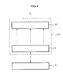
- FIG. 1 is a view schematically illustrating a test apparatus for a power supply unit, according to an embodiment of the present invention.
- FIG. 2 is an exploded perspective view schematically illustrating a test apparatus for a power supply unit, according to an embodiment of the present invention.
- a test apparatus 1 for a power supply unit P includes a body unit 10 and a test unit 20.
- the test apparatus 1 may detect a flicker of a light emitting diode (LED) L.
- the flicker is caused by abnormal power supply of the power supply unit P that supplies power to the LED L. That is, the test apparatus 1 for the power supply unit P tests a power supply state of the power supply unit P through the LED L.
- LED light emitting diode
- the body unit 10 may include a space to receive the LED L, accordingly providing a test environment for the LED L.
- the body unit 10 may form a darkroom environment which is isolated to block out external light, except light generated from the LED L, during the test of the LED L for an accurate test of the LED L.
- the body unit 10 may include a first body 11, a second body 12, and a cover 13.
- the first body 11 may receive the LED L connected with the power supply unit P. All of a plurality of the LEDs L may be inserted in the first body 11 for simultaneous inspection of the flicker.
- the first body 11 may include a heat radiation member H, for example a heat sink, to radiate heat generated during driving in contact with the LED L.
- the heat radiation member H is inserted in the first body 11 along with the LED L.
- the second body 12 may be inserted in the test unit 20 that will be described hereinafter, and configured to be separable from the first body 11.
- the second body 12 may be stacked on an upper portion of the first body 11 to be separable in a vertical direction, that is, a y-axis direction. Accordingly, the upper portion of the first body 11 and a lower portion of the second body 12, facing each other, may be opened respectively.
- the cover 13 may selectively open the second body 12, thereby selectively exposing the test unit 20.
- the cover 13 selectively exposes the test unit 20 built in the second body 12, to enable maintenance and repair or variation of test conditions.
- the cover 13 may be configured to selectively open and close an exposure hole 14 formed through one side of the second body 12.
- the test unit 20 may be mounted in the body unit 10 to face the LED L, such that a distance with respect to the LED L is adjustable.
- the test unit 20 inspects the flicker occurring in the LED L.
- the test unit 20 may include a sensor unit 21 and an adjustment unit 24 as shown in FIGS. 2 and 3 .
- the sensor unit 21 may detect the flicker of the LED L occurring when power supply by the power supply unit P is performed abnormally.
- the sensor unit 21 may include a sensor 22 to detect light, and a substrate 23 electrically connected with the sensor 22 to process detected information.
- the sensor 22 includes a photodiode.
- the adjustment unit 24 may support the sensor unit 21, thereby adjusting a distance G between the sensor unit 21 and the LED L.
- the adjustment unit 24 may include a holder member 25, a support member 26, and a fixing member 27.
- the distance G between the sensor unit 21 and the LED L is within a range of about 10 millimeters (mm) to about 80 mm, however, is not limited thereto.
- the holder member 25 may support the sensor unit 21 such that the sensor unit 21 and the LED L face each other.
- the sensor unit 21 and the LED L face each other in the vertical direction, that is, the y-axis direction.
- the sensor unit 21 and the LED L may face each other in a horizontal direction, that is, in an x-axis direction.
- the first body 11 and the second body 12 may be connected in the x-axis direction.
- the substrate 23 of the sensor unit 21 provided to the holder member 25 may be totally separated for maintenance and repair.
- the support member 26 may be mounted to the body unit 10 by passing through the holder member 25, parallel to the y-axis direction in which the holder member 25 and the LED L face each other.
- the support member 26 may be connected to the holder member 25 by a connection hole 25a formed through one side of the holder member 25, the one side at which the sensor unit 21 is not disposed.
- One end of the support member 26 is fixed to an inside of the second body 12.
- the other end of the support member 26 is fixed by a support end 12a formed at the second body 12 so that a position of the support member 26 is fixed.
- the holder member 25 moves up and down along the support member 26 in the y-axis direction, thereby adjusting the distance G between the sensor 21 and the LED L.
- the fixing member 27 is inserted through the holder member 25 and fixed to at least one of a plurality of fixing recesses 26a provided at the support member 26. Specifically, the fixing member 27 is inserted in the at least one of the plurality of fixing recesses 26a, through one end of the holder member 25 in the x-axis direction, that is, perpendicular to the y-axis direction in which the holder member 25 and the LED L face each other. As shown in FIG. 3 , the fixing member 27 includes a grab end 28 grabbed by an operator, and a fixing end 29 extended from the grab end 28 and inserted in the at least one of the plurality of fixing recesses 26a.
- the fixing member 27 may face the exposure hole formed at the second body 12 so as to be selectively exposed by the cover 13. According to the foregoing configuration, when the inside of the second body 12 is opened by the cover 13, the operator may easily access an inside of the body unit 10 through the exposure hole 14 and operate the fixing member 27.
- test operation of the test apparatus 1 for the power supply unit according to the embodiment of the present invention will now be described with reference to FIGS. 2 and 3 .
- FIG. 3 is a sectional view schematically illustrating the test apparatus for a power supply unit, shown in FIG. 2 .
- the LED L and the test unit 20 including the sensor unit 21 are disposed in the first body 11 and the second body 12, respectively.
- the LED L emits light through connection with the power supply unit P.
- the first body 11 and the second body 12 are connected to each other, an inside space defined by the first body 11 and the second body 12 is sealed, accordingly achieving the darkroom environment.
- the sensor 22 of the sensor unit 21 facing the LED L may detect the flicker of the LED L, generated by abnormal power supply, and may provide the substrate 23 with information on the detected flicker.
- the operator may separate the cover 13 connected with the exposure hole 14 of the second body 12, as shown in FIG 2 , and enter the inside of the second body 12.
- the operator may separate the fixing member 27 fixed by engagement with one of the plurality of fixing recesses 26a formed at the support member 26 as shown in FIG 3 , and then move the released holder member 25 in the y-axis direction to a desired position.
- the operator may reinsert the fixing member 27 into one of the plurality of fixing recesses 26a, which is disposed in the connection hole 25a of the holder member 25, in the x-axis direction.
- the operator repositions and fixes the holder member 25.
- the second body 12 is separated from the first body 11 so that the LED L inserted in the first body 11 is exposed.
- an operator may easily access the inside of the body unit through an openable cover. Therefore, operability in the test may be increased.
Landscapes
- Physics & Mathematics (AREA)
- General Physics & Mathematics (AREA)
- Optics & Photonics (AREA)
- Arrangement Of Elements, Cooling, Sealing, Or The Like Of Lighting Devices (AREA)
- Testing Of Individual Semiconductor Devices (AREA)
- Led Devices (AREA)
Description
- The present invention relates to a test apparatus for a power supply unit, the test apparatus for testing quality of a light emitting diode (LED), and more particularly, to a test apparatus for a power supply unit, capable of testing a power supply state of the power supply unit through a flicker of an LED.
- A light emitting diode (LED) refers to a light source that emits light by converting electrical energy to optical energy. The LED exhibits a high response rate and low power consumption. Moreover, the LED has a long lifespan and therefore is environmental-friendly. Accordingly, the LED is widely applied to various fields such as a backlight source of a display device or a light source of lighting.
- The LED emits light by being supplied with power through a predetermined power supply unit. When power supplied by the power supply unit is unstable, the light emitted from the LED may flicker as an indicator of a malfunction. That is, a flicker of the LED occurs when a current waveform of the power supplied to the LED is imbalanced.
- Generally, a flicker showing a power supply state of a manufactured LED is checked by naked eyes of an operator. However, when the flicker is inspected by an operator, it is difficult to obtain objective data due to individual differences among operators. Accordingly, there is a desire for a method of accurately detecting the flicker of the LED so as to increase a quality of a power supply with respect to the LED.
- RONG C ET AL: "Flickermeter used for different types of lamps", ELECTRICAL POWER QUALITY AND UTILISATION, 2007, 9TH INTERNATIONAL CONFERENCE ON, IEEE, 9 October 2007, pages 1-6, XP031226065, ISBN: 978-84-690-9441-9 discloses a flickermeter that can be used for different types of lamps, including LED lamps.
- TAEKHYUN KIM ET AL: "LED Lamp Flicker Caused by Interharmonics", INSTRUMENTATION AND MEASUREMENT TECHNOLOGY CONFERENCE PROCEEDINGS, 2008, IEEE, PISCATAWAY, NJ, USA, 12 May 2008, pages 1920-1925, XP031274921, ISBN: 978-1-4244-1540-3 studies LED lamp flicker caused by interharmonics.
- It is the object of the present invention to provide an improved test apparatus with a body unit configured to receive an LED and a test unit mounted in the body unit to face the LED so that the test unit can detect a flicker of the LED that occurs when a supply state of power applied to the LED is abnormal.
- The object is solved by the subject matter of the independent claim.
- Preferred embodiments of the present invention are defined by the dependent claims.
- An aspect of the present invention provides a test apparatus for a power supply unit, the test apparatus that increases quality of power supply with respect to a light emitting diode (LED) by detecting flicker of the LED.
- According to an aspect of the present invention, there is provided a test apparatus for a power supply unit, the test apparatus including a body unit configured to define a space to receive an LED and to provide a test environment to test a supply state of power applied to the LED, and a test unit mounted in the body unit to face the LED and configured to detect a flicker of the LED occurring when power supply is abnormal.
- The test unit may be configured such that a distance with respect to the LED is adjustable.
- The body unit may provide a darkroom environment isolated from an outside.
- The body unit may include a first body configured to receive the LED, a second body configured to receive the test unit and to be separable from the first body, and a cover configured to selectively open at least a part of the second body, thereby selectively exposing the test unit.
- The test unit may include a sensor unit configured to detect a flicker of light generated from the LED, and an adjustment unit configured to support the sensor unit and adjust a distance between the sensor unit and the LED.
- The sensor unit may include a photodiode.
- The control unit may include a holder member configured to support the sensor unit such that the sensor unit faces the LED, a support member mounted to the body unit by passing through the holder member parallel to a direction in which the holder member and the LED face each other, and configured to include a plurality of fixing recesses, and a fixing member configured to be engaged with at least one of the plurality of fixing recesses of the support member through the holder member, thereby selectively fixing a position of the holder member with respect to the support member.
- The body unit may include a heat radiation member disposed in the body unit to radiate heat generated from the LED.
- According to another aspect of the present invention, there is provided a test apparatus for a power supply unit, the test apparatus including a body unit configured to include a space to receive an LED, and a test unit mounted in the body unit and configured to test a supply state of power applied to the LED through a flicker of light generated from the LED, wherein the body unit is openable to selectively expose the LED and the test unit to the outside.
- The test unit may face the LED such that a distance with respect to the LED is adjustable.
- The body unit may include a first body configured to receive the LED, a second body configured to receive the test unit and to be separable from the first body, and a cover configured to selectively expose an exposure hole formed through one side surface of the second body, the one side surface facing the test unit.
- The test unit may include a sensor unit configured to detect the flicker of the light generated from the LED, and an adjustment unit configured to adjust a distance between the sensor unit and the LED by including a holder member supporting the sensor unit such that the sensor unit faces the LED, a support member mounted to the body unit by passing through the holder member parallel to a direction in which the holder member and the LED face each other, and a fixing member configured to selectively fix a position of the holder member with respect to the support member.
- The body unit may include a heat radiation member disposed in the body unit to radiate heat generated from the LED.
- These and/or other aspects, features, and advantages of the invention will become apparent and more readily appreciated from the following description of exemplary embodiments, taken in conjunction with the accompanying drawings of which:
-
FIG. 1 is a view schematically illustrating a test apparatus for a power supply unit, according to an embodiment of the present invention; -
FIG. 2 is an exploded perspective view schematically illustrating a test apparatus for a power supply unit, according to an embodiment of the present invention; -
FIG. 3 is a sectional view schematically illustrating the test apparatus for a power supply unit, shown inFIG. 2 . - Reference will now be made in detail to exemplary embodiments of the present invention, examples of which are illustrated in the accompanying drawings, wherein like reference numerals refer to the like elements throughout. Exemplary embodiments are described below to explain the present invention by referring to the figures.
-
FIG. 1 is a view schematically illustrating a test apparatus for a power supply unit, according to an embodiment of the present invention.FIG. 2 is an exploded perspective view schematically illustrating a test apparatus for a power supply unit, according to an embodiment of the present invention. - Referring to
FIGS. 1 and2 , atest apparatus 1 for a power supply unit P, according to an embodiment of the present invention, includes abody unit 10 and atest unit 20. - The
test apparatus 1 may detect a flicker of a light emitting diode (LED) L. The flicker is caused by abnormal power supply of the power supply unit P that supplies power to the LED L. That is, thetest apparatus 1 for the power supply unit P tests a power supply state of the power supply unit P through the LED L. - The
body unit 10 may include a space to receive the LED L, accordingly providing a test environment for the LED L. Thebody unit 10 may form a darkroom environment which is isolated to block out external light, except light generated from the LED L, during the test of the LED L for an accurate test of the LED L. As shown inFIG. 2 , thebody unit 10 may include afirst body 11, asecond body 12, and acover 13. - The
first body 11 may receive the LED L connected with the power supply unit P. All of a plurality of the LEDs L may be inserted in thefirst body 11 for simultaneous inspection of the flicker. In addition, thefirst body 11 may include a heat radiation member H, for example a heat sink, to radiate heat generated during driving in contact with the LED L. The heat radiation member H is inserted in thefirst body 11 along with the LED L. - The
second body 12 may be inserted in thetest unit 20 that will be described hereinafter, and configured to be separable from thefirst body 11. Here, thesecond body 12 may be stacked on an upper portion of thefirst body 11 to be separable in a vertical direction, that is, a y-axis direction. Accordingly, the upper portion of thefirst body 11 and a lower portion of thesecond body 12, facing each other, may be opened respectively. - The
cover 13 may selectively open thesecond body 12, thereby selectively exposing thetest unit 20. In particular, thecover 13 selectively exposes thetest unit 20 built in thesecond body 12, to enable maintenance and repair or variation of test conditions. For this purpose, thecover 13 may be configured to selectively open and close anexposure hole 14 formed through one side of thesecond body 12. - The
test unit 20 may be mounted in thebody unit 10 to face the LED L, such that a distance with respect to the LED L is adjustable. Thetest unit 20 inspects the flicker occurring in the LED L. For this purpose, thetest unit 20 may include asensor unit 21 and anadjustment unit 24 as shown inFIGS. 2 and3 . - The
sensor unit 21 may detect the flicker of the LED L occurring when power supply by the power supply unit P is performed abnormally. For this function, thesensor unit 21 may include asensor 22 to detect light, and asubstrate 23 electrically connected with thesensor 22 to process detected information. According to the present embodiment, thesensor 22 includes a photodiode. - The
adjustment unit 24 may support thesensor unit 21, thereby adjusting a distance G between thesensor unit 21 and the LED L. As shown inFIG. 3 , theadjustment unit 24 may include aholder member 25, asupport member 26, and afixing member 27. According to the present embodiment, the distance G between thesensor unit 21 and the LED L is within a range of about 10 millimeters (mm) to about 80 mm, however, is not limited thereto. - The
holder member 25 may support thesensor unit 21 such that thesensor unit 21 and the LED L face each other. Referring toFIGS. 2 and3 , since the LED L and thesensor unit 21 are disposed in thefirst body 11 and thesecond body 12 being vertically stacked, thesensor unit 21 and the LED L face each other in the vertical direction, that is, the y-axis direction. However, thesensor unit 21 and the LED L may face each other in a horizontal direction, that is, in an x-axis direction. In this case, thefirst body 11 and thesecond body 12 may be connected in the x-axis direction. - The
substrate 23 of thesensor unit 21 provided to theholder member 25 may be totally separated for maintenance and repair. - The
support member 26 may be mounted to thebody unit 10 by passing through theholder member 25, parallel to the y-axis direction in which theholder member 25 and the LED L face each other. Thesupport member 26 may be connected to theholder member 25 by aconnection hole 25a formed through one side of theholder member 25, the one side at which thesensor unit 21 is not disposed. One end of thesupport member 26 is fixed to an inside of thesecond body 12. The other end of thesupport member 26 is fixed by asupport end 12a formed at thesecond body 12 so that a position of thesupport member 26 is fixed. According to the foregoing configuration, theholder member 25 moves up and down along thesupport member 26 in the y-axis direction, thereby adjusting the distance G between thesensor 21 and the LED L. - The fixing
member 27 is inserted through theholder member 25 and fixed to at least one of a plurality of fixingrecesses 26a provided at thesupport member 26. Specifically, the fixingmember 27 is inserted in the at least one of the plurality of fixingrecesses 26a, through one end of theholder member 25 in the x-axis direction, that is, perpendicular to the y-axis direction in which theholder member 25 and the LED L face each other. As shown inFIG. 3 , the fixingmember 27 includes agrab end 28 grabbed by an operator, and a fixingend 29 extended from thegrab end 28 and inserted in the at least one of the plurality of fixingrecesses 26a. - The fixing
member 27 may face the exposure hole formed at thesecond body 12 so as to be selectively exposed by thecover 13. According to the foregoing configuration, when the inside of thesecond body 12 is opened by thecover 13, the operator may easily access an inside of thebody unit 10 through theexposure hole 14 and operate the fixingmember 27. - A test operation of the
test apparatus 1 for the power supply unit according to the embodiment of the present invention will now be described with reference toFIGS. 2 and3 . -
FIG. 3 is a sectional view schematically illustrating the test apparatus for a power supply unit, shown inFIG. 2 . - As shown in
FIG. 2 , the LED L and thetest unit 20 including thesensor unit 21 are disposed in thefirst body 11 and thesecond body 12, respectively. The LED L emits light through connection with the power supply unit P. - As the
first body 11 and thesecond body 12 are connected to each other, an inside space defined by thefirst body 11 and thesecond body 12 is sealed, accordingly achieving the darkroom environment. When the LED L disposed in thefirst body 11 is operated, thesensor 22 of thesensor unit 21 facing the LED L may detect the flicker of the LED L, generated by abnormal power supply, and may provide thesubstrate 23 with information on the detected flicker. - When the flicker is inspected by adjusting the distance G between the LED L and the
sensor unit 21 provided respectively in thefirst body 11 and thesecond body 12, the operator may separate thecover 13 connected with theexposure hole 14 of thesecond body 12, as shown inFIG 2 , and enter the inside of thesecond body 12. Next, the operator may separate the fixingmember 27 fixed by engagement with one of the plurality of fixingrecesses 26a formed at thesupport member 26 as shown inFIG 3 , and then move the releasedholder member 25 in the y-axis direction to a desired position. Finally, the operator may reinsert the fixingmember 27 into one of the plurality of fixingrecesses 26a, which is disposed in theconnection hole 25a of theholder member 25, in the x-axis direction. Thus, the operator repositions and fixes theholder member 25. - When the operator wants to replace the LED L being tested, the
second body 12 is separated from thefirst body 11 so that the LED L inserted in thefirst body 11 is exposed. - According to the foregoing structure, by inspecting a flicker of light generated from an LED, power supply with respect to the LED may be detected and analyzed, regularly.
- Since a distance between the LED and a test unit that detects the flicker of the LED is selectively adjusted, various test conditions may be provided. As a consequence, power supply quality may be increased.
- Since a darkroom environment is provided by blocking out external light during a test of the LED, accuracy of the test may be increased.
- Since an inside of a body unit is selectively opened to exposure the LED, replacement of the LED may be facilitated.
- In addition, an operator may easily access the inside of the body unit through an openable cover. Therefore, operability in the test may be increased.
- Although a few exemplary embodiments of the present invention have been shown and described, the present invention is not limited to the described exemplary embodiments. Instead, it would be appreciated by those skilled in the art that changes may be made to these exemplary embodiments without departing from the principles of the invention, the scope of which is defined by the claims.
Claims (5)
- A test apparatus for a power supply unit, the test apparatus comprising:a body unit (10) configured to define a space to receive a light emitting diode, LED (L),and to provide a test environment to test a supply state of power applied to the LED; anda test unit (20) mounted in the body unit to face the LED and configured to detect a flicker of the LED occurring when the power supply state is abnormal;wherein the body unit (10) comprises:a first body (11) configured to receive the LED (L);a second body (12) configured to receive the test unit and to be separable from the first body; anda cover (13) configured to selectively open at least a part of the second body, thereby selectively exposing the test unit; andwherein the test unit (20) comprises:a sensor unit (21) configured to detect the flicker of light generated from the LED (L); andan adjustment unit (24) configured to support the sensor unit and adjust a distance between the sensor unit and the LED.
- The test apparatus of claim 1, wherein the body unit (10) provides a darkroom environment isolated from an outside.
- The test apparatus of claim 1, wherein the sensor unit (21) comprises a photodiode.
- The test apparatus of claim 1, wherein the adjustment unit (24) comprises:a holder member (25) configured to support the sensor unit (21) such that the sensor unit faces the LED (L);a support member (26) mounted to the body unit (10) by passing through the holder member parallel to a direction in which the holder member and the LED face each other,and configured to comprise a plurality of fixing recesses; anda fixing member (27) configured to be engaged with at least one of the plurality of fixing recesses of the support member through the holder member, thereby selectively fixing a position of the holder member with respect to the support member.
- The test apparatus of claim 1, wherein the body unit (10) comprises a heat radiation member (H) disposed in the body unit to radiate heat generated from the LED (L).
Applications Claiming Priority (1)
| Application Number | Priority Date | Filing Date | Title |
|---|---|---|---|
| KR1020100126253A KR101717667B1 (en) | 2010-12-10 | 2010-12-10 | Test apparatus for power supply unit |
Publications (2)
| Publication Number | Publication Date |
|---|---|
| EP2463675A1 EP2463675A1 (en) | 2012-06-13 |
| EP2463675B1 true EP2463675B1 (en) | 2013-11-13 |
Family
ID=45440142
Family Applications (1)
| Application Number | Title | Priority Date | Filing Date |
|---|---|---|---|
| EP11192737.2A Not-in-force EP2463675B1 (en) | 2010-12-10 | 2011-12-09 | Test apparatus for power supply unit |
Country Status (5)
| Country | Link |
|---|---|
| US (1) | US8779755B2 (en) |
| EP (1) | EP2463675B1 (en) |
| KR (1) | KR101717667B1 (en) |
| CN (1) | CN102565720B (en) |
| TW (1) | TWI448888B (en) |
Families Citing this family (7)
| Publication number | Priority date | Publication date | Assignee | Title |
|---|---|---|---|---|
| CN102928792A (en) * | 2012-11-06 | 2013-02-13 | 中山新特丽照明电器有限公司 | LED drive power comprehensive tester |
| KR102257672B1 (en) * | 2016-12-09 | 2021-05-28 | 삼성에스디아이 주식회사 | Power evaluating apparatus |
| JP2019045232A (en) * | 2017-08-31 | 2019-03-22 | セイコーエプソン株式会社 | Electronic component conveyance device and electronic component inspection device |
| CN107831451B (en) * | 2017-10-17 | 2024-02-09 | 中山市金兴智能技术有限公司 | LED driving power comprehensive tester |
| CN111812540A (en) * | 2020-07-21 | 2020-10-23 | 广州海关技术中心 | Load cabinet for harmonic wave and scintillation test |
| CN112986787B (en) * | 2021-05-20 | 2021-07-30 | 江西省兆驰光电有限公司 | Light-emitting diode testing device |
| CN113721164B (en) * | 2021-09-01 | 2024-05-07 | 航达康机电技术(武汉)有限公司 | Low-cost high-efficiency navigation lamp testing device and testing method thereof |
Family Cites Families (10)
| Publication number | Priority date | Publication date | Assignee | Title |
|---|---|---|---|---|
| JPS58202849A (en) * | 1982-05-21 | 1983-11-26 | Matsushita Electric Ind Co Ltd | How to measure discharge lamp flickering |
| US4953947A (en) | 1986-08-08 | 1990-09-04 | Corning Incorporated | Dispersion transformer having multichannel fiber |
| US5239495A (en) * | 1989-06-23 | 1993-08-24 | Kabushiki Kaisha Toshiba | Power supply control system for a portable computer |
| US5663763A (en) | 1992-10-29 | 1997-09-02 | Sony Corp. | Picture signal encoding method and apparatus and picture signal decoding method and apparatus |
| KR20020069943A (en) | 2001-02-28 | 2002-09-05 | 김남식 | cutting section forming method of attaching materials |
| CN2564849Y (en) | 2002-08-21 | 2003-08-06 | 财团法人工业技术研究院 | Photoelectric lighting module |
| JP4804084B2 (en) * | 2005-09-15 | 2011-10-26 | 三和シヤッター工業株式会社 | Electric shutter |
| KR20070070652A (en) * | 2005-12-29 | 2007-07-04 | 노틸러스효성 주식회사 | Optical sensor detection performance measuring device |
| TW201001152A (en) | 2008-06-27 | 2010-01-01 | Hon Hai Prec Ind Co Ltd | Power source alarm system and method thereof |
| JP2010096521A (en) * | 2008-10-14 | 2010-04-30 | Omron Corp | Flickering detection device |
-
2010
- 2010-12-10 KR KR1020100126253A patent/KR101717667B1/en active Active
-
2011
- 2011-12-09 TW TW100145492A patent/TWI448888B/en not_active IP Right Cessation
- 2011-12-09 EP EP11192737.2A patent/EP2463675B1/en not_active Not-in-force
- 2011-12-09 US US13/316,075 patent/US8779755B2/en not_active Expired - Fee Related
- 2011-12-09 CN CN201110416058.0A patent/CN102565720B/en not_active Expired - Fee Related
Also Published As
| Publication number | Publication date |
|---|---|
| TWI448888B (en) | 2014-08-11 |
| CN102565720A (en) | 2012-07-11 |
| US8779755B2 (en) | 2014-07-15 |
| TW201234174A (en) | 2012-08-16 |
| EP2463675A1 (en) | 2012-06-13 |
| US20120146622A1 (en) | 2012-06-14 |
| KR101717667B1 (en) | 2017-03-20 |
| CN102565720B (en) | 2015-01-14 |
| KR20120064972A (en) | 2012-06-20 |
Similar Documents
| Publication | Publication Date | Title |
|---|---|---|
| US8779755B2 (en) | Apparatus for testing power supply units based on light emitting diode flickers | |
| CN107466362B (en) | Cooled photomultiplier-based light detector with reduced condensation and related apparatus and method | |
| KR100768884B1 (en) | Light emitting device inspection device of substrate | |
| KR101987506B1 (en) | Measurement apparatus and measurement method | |
| JP2019075434A (en) | Prober device and wafer chuck | |
| US9778347B2 (en) | Target holding jig and measurement apparatus | |
| JP2005172665A (en) | Optical radiation pattern measuring device | |
| CN104075879A (en) | Light emitting diode measurement device | |
| JP2007019237A (en) | Probing device for double-sided light emitting element | |
| CN104237128A (en) | Fixed device and measuring method for light transmittance measurement | |
| JP2010238906A (en) | Solar cell output characteristic measuring apparatus and output characteristic measuring method | |
| CN112670201B (en) | Detection device | |
| KR101555019B1 (en) | Apparatus for Aging and Optical Test of Photonics Devices in Real Time | |
| JP5848583B2 (en) | Solar cell related sample measurement system | |
| KR101538427B1 (en) | LED Socket for Testing Spectrum Property | |
| CN113125003A (en) | Light generating device | |
| WO2021077548A1 (en) | Quantum dot fluorescence detection device, and quantum dot fluorescence monitor and monitoring method thereof | |
| CN102023085B (en) | Light-emitting element testing device and sensing module thereof | |
| KR101015792B1 (en) | Inspection jig for side emitting LED array | |
| KR20130077652A (en) | LED module inspection device | |
| KR20230042975A (en) | Probe station for detecting electrical, thermal and optical characteristics of device | |
| JP2011059118A (en) | Detection module for light emitting device, and testing device using the same | |
| RU194910U1 (en) | Accessories for checking photodiode boards | |
| KR101243820B1 (en) | Insection appratus for image display panel | |
| JP5813861B2 (en) | Measuring device for semiconductor light emitting element and measuring method for semiconductor light emitting element |
Legal Events
| Date | Code | Title | Description |
|---|---|---|---|
| PUAI | Public reference made under article 153(3) epc to a published international application that has entered the european phase |
Free format text: ORIGINAL CODE: 0009012 |
|
| 17P | Request for examination filed |
Effective date: 20111209 |
|
| AK | Designated contracting states |
Kind code of ref document: A1 Designated state(s): AL AT BE BG CH CY CZ DE DK EE ES FI FR GB GR HR HU IE IS IT LI LT LU LV MC MK MT NL NO PL PT RO RS SE SI SK SM TR |
|
| AX | Request for extension of the european patent |
Extension state: BA ME |
|
| RAP1 | Party data changed (applicant data changed or rights of an application transferred) |
Owner name: SAMSUNG ELECTRONICS CO., LTD. |
|
| GRAP | Despatch of communication of intention to grant a patent |
Free format text: ORIGINAL CODE: EPIDOSNIGR1 |
|
| INTG | Intention to grant announced |
Effective date: 20130517 |
|
| GRAS | Grant fee paid |
Free format text: ORIGINAL CODE: EPIDOSNIGR3 |
|
| GRAA | (expected) grant |
Free format text: ORIGINAL CODE: 0009210 |
|
| AK | Designated contracting states |
Kind code of ref document: B1 Designated state(s): AL AT BE BG CH CY CZ DE DK EE ES FI FR GB GR HR HU IE IS IT LI LT LU LV MC MK MT NL NO PL PT RO RS SE SI SK SM TR |
|
| REG | Reference to a national code |
Ref country code: GB Ref legal event code: FG4D |
|
| REG | Reference to a national code |
Ref country code: CH Ref legal event code: EP |
|
| REG | Reference to a national code |
Ref country code: AT Ref legal event code: REF Ref document number: 640784 Country of ref document: AT Kind code of ref document: T Effective date: 20131215 |
|
| REG | Reference to a national code |
Ref country code: IE Ref legal event code: FG4D |
|
| REG | Reference to a national code |
Ref country code: NL Ref legal event code: T3 |
|
| REG | Reference to a national code |
Ref country code: DE Ref legal event code: R096 Ref document number: 602011003695 Country of ref document: DE Effective date: 20140109 |
|
| REG | Reference to a national code |
Ref country code: AT Ref legal event code: MK05 Ref document number: 640784 Country of ref document: AT Kind code of ref document: T Effective date: 20131113 |
|
| REG | Reference to a national code |
Ref country code: LT Ref legal event code: MG4D |
|
| PG25 | Lapsed in a contracting state [announced via postgrant information from national office to epo] |
Ref country code: IS Free format text: LAPSE BECAUSE OF FAILURE TO SUBMIT A TRANSLATION OF THE DESCRIPTION OR TO PAY THE FEE WITHIN THE PRESCRIBED TIME-LIMIT Effective date: 20140313 Ref country code: NO Free format text: LAPSE BECAUSE OF FAILURE TO SUBMIT A TRANSLATION OF THE DESCRIPTION OR TO PAY THE FEE WITHIN THE PRESCRIBED TIME-LIMIT Effective date: 20140213 Ref country code: LT Free format text: LAPSE BECAUSE OF FAILURE TO SUBMIT A TRANSLATION OF THE DESCRIPTION OR TO PAY THE FEE WITHIN THE PRESCRIBED TIME-LIMIT Effective date: 20131113 Ref country code: FI Free format text: LAPSE BECAUSE OF FAILURE TO SUBMIT A TRANSLATION OF THE DESCRIPTION OR TO PAY THE FEE WITHIN THE PRESCRIBED TIME-LIMIT Effective date: 20131113 Ref country code: HR Free format text: LAPSE BECAUSE OF FAILURE TO SUBMIT A TRANSLATION OF THE DESCRIPTION OR TO PAY THE FEE WITHIN THE PRESCRIBED TIME-LIMIT Effective date: 20131113 Ref country code: SE Free format text: LAPSE BECAUSE OF FAILURE TO SUBMIT A TRANSLATION OF THE DESCRIPTION OR TO PAY THE FEE WITHIN THE PRESCRIBED TIME-LIMIT Effective date: 20131113 |
|
| PG25 | Lapsed in a contracting state [announced via postgrant information from national office to epo] |
Ref country code: RS Free format text: LAPSE BECAUSE OF FAILURE TO SUBMIT A TRANSLATION OF THE DESCRIPTION OR TO PAY THE FEE WITHIN THE PRESCRIBED TIME-LIMIT Effective date: 20131113 Ref country code: BE Free format text: LAPSE BECAUSE OF FAILURE TO SUBMIT A TRANSLATION OF THE DESCRIPTION OR TO PAY THE FEE WITHIN THE PRESCRIBED TIME-LIMIT Effective date: 20131113 Ref country code: ES Free format text: LAPSE BECAUSE OF FAILURE TO SUBMIT A TRANSLATION OF THE DESCRIPTION OR TO PAY THE FEE WITHIN THE PRESCRIBED TIME-LIMIT Effective date: 20131113 Ref country code: AT Free format text: LAPSE BECAUSE OF FAILURE TO SUBMIT A TRANSLATION OF THE DESCRIPTION OR TO PAY THE FEE WITHIN THE PRESCRIBED TIME-LIMIT Effective date: 20131113 Ref country code: LV Free format text: LAPSE BECAUSE OF FAILURE TO SUBMIT A TRANSLATION OF THE DESCRIPTION OR TO PAY THE FEE WITHIN THE PRESCRIBED TIME-LIMIT Effective date: 20131113 Ref country code: CY Free format text: LAPSE BECAUSE OF FAILURE TO SUBMIT A TRANSLATION OF THE DESCRIPTION OR TO PAY THE FEE WITHIN THE PRESCRIBED TIME-LIMIT Effective date: 20131113 |
|
| PG25 | Lapsed in a contracting state [announced via postgrant information from national office to epo] |
Ref country code: PT Free format text: LAPSE BECAUSE OF FAILURE TO SUBMIT A TRANSLATION OF THE DESCRIPTION OR TO PAY THE FEE WITHIN THE PRESCRIBED TIME-LIMIT Effective date: 20140313 |
|
| PG25 | Lapsed in a contracting state [announced via postgrant information from national office to epo] |
Ref country code: EE Free format text: LAPSE BECAUSE OF FAILURE TO SUBMIT A TRANSLATION OF THE DESCRIPTION OR TO PAY THE FEE WITHIN THE PRESCRIBED TIME-LIMIT Effective date: 20131113 |
|
| REG | Reference to a national code |
Ref country code: DE Ref legal event code: R097 Ref document number: 602011003695 Country of ref document: DE |
|
| PG25 | Lapsed in a contracting state [announced via postgrant information from national office to epo] |
Ref country code: SK Free format text: LAPSE BECAUSE OF FAILURE TO SUBMIT A TRANSLATION OF THE DESCRIPTION OR TO PAY THE FEE WITHIN THE PRESCRIBED TIME-LIMIT Effective date: 20131113 Ref country code: CZ Free format text: LAPSE BECAUSE OF FAILURE TO SUBMIT A TRANSLATION OF THE DESCRIPTION OR TO PAY THE FEE WITHIN THE PRESCRIBED TIME-LIMIT Effective date: 20131113 Ref country code: PL Free format text: LAPSE BECAUSE OF FAILURE TO SUBMIT A TRANSLATION OF THE DESCRIPTION OR TO PAY THE FEE WITHIN THE PRESCRIBED TIME-LIMIT Effective date: 20131113 Ref country code: RO Free format text: LAPSE BECAUSE OF FAILURE TO SUBMIT A TRANSLATION OF THE DESCRIPTION OR TO PAY THE FEE WITHIN THE PRESCRIBED TIME-LIMIT Effective date: 20131113 |
|
| PLBE | No opposition filed within time limit |
Free format text: ORIGINAL CODE: 0009261 |
|
| STAA | Information on the status of an ep patent application or granted ep patent |
Free format text: STATUS: NO OPPOSITION FILED WITHIN TIME LIMIT |
|
| REG | Reference to a national code |
Ref country code: IE Ref legal event code: MM4A |
|
| REG | Reference to a national code |
Ref country code: FR Ref legal event code: ST Effective date: 20140829 |
|
| PG25 | Lapsed in a contracting state [announced via postgrant information from national office to epo] |
Ref country code: DK Free format text: LAPSE BECAUSE OF FAILURE TO SUBMIT A TRANSLATION OF THE DESCRIPTION OR TO PAY THE FEE WITHIN THE PRESCRIBED TIME-LIMIT Effective date: 20131113 |
|
| 26N | No opposition filed |
Effective date: 20140814 |
|
| PG25 | Lapsed in a contracting state [announced via postgrant information from national office to epo] |
Ref country code: IE Free format text: LAPSE BECAUSE OF NON-PAYMENT OF DUE FEES Effective date: 20131209 |
|
| REG | Reference to a national code |
Ref country code: DE Ref legal event code: R097 Ref document number: 602011003695 Country of ref document: DE Effective date: 20140814 |
|
| PG25 | Lapsed in a contracting state [announced via postgrant information from national office to epo] |
Ref country code: FR Free format text: LAPSE BECAUSE OF NON-PAYMENT OF DUE FEES Effective date: 20140113 |
|
| PG25 | Lapsed in a contracting state [announced via postgrant information from national office to epo] |
Ref country code: SI Free format text: LAPSE BECAUSE OF FAILURE TO SUBMIT A TRANSLATION OF THE DESCRIPTION OR TO PAY THE FEE WITHIN THE PRESCRIBED TIME-LIMIT Effective date: 20131113 |
|
| PG25 | Lapsed in a contracting state [announced via postgrant information from national office to epo] |
Ref country code: MC Free format text: LAPSE BECAUSE OF FAILURE TO SUBMIT A TRANSLATION OF THE DESCRIPTION OR TO PAY THE FEE WITHIN THE PRESCRIBED TIME-LIMIT Effective date: 20131113 |
|
| PG25 | Lapsed in a contracting state [announced via postgrant information from national office to epo] |
Ref country code: SM Free format text: LAPSE BECAUSE OF FAILURE TO SUBMIT A TRANSLATION OF THE DESCRIPTION OR TO PAY THE FEE WITHIN THE PRESCRIBED TIME-LIMIT Effective date: 20131113 Ref country code: TR Free format text: LAPSE BECAUSE OF FAILURE TO SUBMIT A TRANSLATION OF THE DESCRIPTION OR TO PAY THE FEE WITHIN THE PRESCRIBED TIME-LIMIT Effective date: 20131113 |
|
| PG25 | Lapsed in a contracting state [announced via postgrant information from national office to epo] |
Ref country code: LU Free format text: LAPSE BECAUSE OF NON-PAYMENT OF DUE FEES Effective date: 20131209 Ref country code: HU Free format text: LAPSE BECAUSE OF FAILURE TO SUBMIT A TRANSLATION OF THE DESCRIPTION OR TO PAY THE FEE WITHIN THE PRESCRIBED TIME-LIMIT; INVALID AB INITIO Effective date: 20111209 Ref country code: BG Free format text: LAPSE BECAUSE OF FAILURE TO SUBMIT A TRANSLATION OF THE DESCRIPTION OR TO PAY THE FEE WITHIN THE PRESCRIBED TIME-LIMIT Effective date: 20131113 Ref country code: MK Free format text: LAPSE BECAUSE OF FAILURE TO SUBMIT A TRANSLATION OF THE DESCRIPTION OR TO PAY THE FEE WITHIN THE PRESCRIBED TIME-LIMIT Effective date: 20131113 |
|
| REG | Reference to a national code |
Ref country code: CH Ref legal event code: PL |
|
| PG25 | Lapsed in a contracting state [announced via postgrant information from national office to epo] |
Ref country code: GR Free format text: LAPSE BECAUSE OF NON-PAYMENT OF DUE FEES Effective date: 20131113 Ref country code: MT Free format text: LAPSE BECAUSE OF FAILURE TO SUBMIT A TRANSLATION OF THE DESCRIPTION OR TO PAY THE FEE WITHIN THE PRESCRIBED TIME-LIMIT Effective date: 20131113 Ref country code: IT Free format text: LAPSE BECAUSE OF FAILURE TO SUBMIT A TRANSLATION OF THE DESCRIPTION OR TO PAY THE FEE WITHIN THE PRESCRIBED TIME-LIMIT Effective date: 20131113 |
|
| PG25 | Lapsed in a contracting state [announced via postgrant information from national office to epo] |
Ref country code: CH Free format text: LAPSE BECAUSE OF NON-PAYMENT OF DUE FEES Effective date: 20141231 Ref country code: LI Free format text: LAPSE BECAUSE OF NON-PAYMENT OF DUE FEES Effective date: 20141231 |
|
| PG25 | Lapsed in a contracting state [announced via postgrant information from national office to epo] |
Ref country code: GR Free format text: LAPSE BECAUSE OF FAILURE TO SUBMIT A TRANSLATION OF THE DESCRIPTION OR TO PAY THE FEE WITHIN THE PRESCRIBED TIME-LIMIT Effective date: 20140214 |
|
| PG25 | Lapsed in a contracting state [announced via postgrant information from national office to epo] |
Ref country code: AL Free format text: LAPSE BECAUSE OF FAILURE TO SUBMIT A TRANSLATION OF THE DESCRIPTION OR TO PAY THE FEE WITHIN THE PRESCRIBED TIME-LIMIT Effective date: 20131113 |
|
| PGFP | Annual fee paid to national office [announced via postgrant information from national office to epo] |
Ref country code: NL Payment date: 20211116 Year of fee payment: 11 Ref country code: GB Payment date: 20211021 Year of fee payment: 11 Ref country code: DE Payment date: 20211027 Year of fee payment: 11 |
|
| REG | Reference to a national code |
Ref country code: DE Ref legal event code: R119 Ref document number: 602011003695 Country of ref document: DE |
|
| REG | Reference to a national code |
Ref country code: NL Ref legal event code: MM Effective date: 20230101 |
|
| GBPC | Gb: european patent ceased through non-payment of renewal fee |
Effective date: 20221209 |
|
| PG25 | Lapsed in a contracting state [announced via postgrant information from national office to epo] |
Ref country code: NL Free format text: LAPSE BECAUSE OF NON-PAYMENT OF DUE FEES Effective date: 20230101 |
|
| PG25 | Lapsed in a contracting state [announced via postgrant information from national office to epo] |
Ref country code: GB Free format text: LAPSE BECAUSE OF NON-PAYMENT OF DUE FEES Effective date: 20221209 Ref country code: DE Free format text: LAPSE BECAUSE OF NON-PAYMENT OF DUE FEES Effective date: 20230701 |