EP2463655A2 - Blood measuring apparatus - Google Patents
Blood measuring apparatus Download PDFInfo
- Publication number
- EP2463655A2 EP2463655A2 EP20110193026 EP11193026A EP2463655A2 EP 2463655 A2 EP2463655 A2 EP 2463655A2 EP 20110193026 EP20110193026 EP 20110193026 EP 11193026 A EP11193026 A EP 11193026A EP 2463655 A2 EP2463655 A2 EP 2463655A2
- Authority
- EP
- European Patent Office
- Prior art keywords
- wall
- chamber
- blood
- diluting solution
- measuring apparatus
- Prior art date
- Legal status (The legal status is an assumption and is not a legal conclusion. Google has not performed a legal analysis and makes no representation as to the accuracy of the status listed.)
- Granted
Links
Images



Classifications
-
- G—PHYSICS
- G01—MEASURING; TESTING
- G01N—INVESTIGATING OR ANALYSING MATERIALS BY DETERMINING THEIR CHEMICAL OR PHYSICAL PROPERTIES
- G01N15/00—Investigating characteristics of particles; Investigating permeability, pore-volume or surface-area of porous materials
- G01N15/10—Investigating individual particles
- G01N15/1031—Investigating individual particles by measuring electrical or magnetic effects
- G01N15/12—Investigating individual particles by measuring electrical or magnetic effects by observing changes in resistance or impedance across apertures when traversed by individual particles, e.g. by using the Coulter principle
-
- G—PHYSICS
- G01—MEASURING; TESTING
- G01N—INVESTIGATING OR ANALYSING MATERIALS BY DETERMINING THEIR CHEMICAL OR PHYSICAL PROPERTIES
- G01N15/00—Investigating characteristics of particles; Investigating permeability, pore-volume or surface-area of porous materials
- G01N15/06—Investigating concentration of particle suspensions
- G01N15/0656—Investigating concentration of particle suspensions using electric, e.g. electrostatic methods or magnetic methods
-
- G—PHYSICS
- G01—MEASURING; TESTING
- G01N—INVESTIGATING OR ANALYSING MATERIALS BY DETERMINING THEIR CHEMICAL OR PHYSICAL PROPERTIES
- G01N15/00—Investigating characteristics of particles; Investigating permeability, pore-volume or surface-area of porous materials
- G01N15/10—Investigating individual particles
- G01N15/1023—Microstructural devices for non-optical measurement
-
- G—PHYSICS
- G01—MEASURING; TESTING
- G01N—INVESTIGATING OR ANALYSING MATERIALS BY DETERMINING THEIR CHEMICAL OR PHYSICAL PROPERTIES
- G01N15/00—Investigating characteristics of particles; Investigating permeability, pore-volume or surface-area of porous materials
- G01N15/10—Investigating individual particles
- G01N15/1031—Investigating individual particles by measuring electrical or magnetic effects
- G01N15/12—Investigating individual particles by measuring electrical or magnetic effects by observing changes in resistance or impedance across apertures when traversed by individual particles, e.g. by using the Coulter principle
- G01N15/13—Details pertaining to apertures
-
- G—PHYSICS
- G01—MEASURING; TESTING
- G01N—INVESTIGATING OR ANALYSING MATERIALS BY DETERMINING THEIR CHEMICAL OR PHYSICAL PROPERTIES
- G01N15/00—Investigating characteristics of particles; Investigating permeability, pore-volume or surface-area of porous materials
- G01N15/10—Investigating individual particles
- G01N2015/1024—Counting particles by non-optical means
Definitions
- a related-art blood measuring apparatus is configured as shown in Fig. 5 .
- An aperture 73 configured by a minute hole is disposed between a first chamber 71 and a second chamber 72.
- An electrode 74 is disposed in the first chamber 71, and an electrode 75 is disposed in the second chamber 72.
- Diluted blood is contained in the first chamber 71, and a diluting solution is contained in the second chamber 72.
- a blood measuring apparatus comprising: a first chamber which includes a first wall provided with an aperture and in which diluted blood is contained; a second chamber which includes the first wall, a second wall opposed to the first wall and a peripheral wall and in which diluting solution is contained, the first and second chambers communicating with each other through the aperture; first and second electrodes which are disposed in the first and second chambers, respectively; a measuring unit which performs a blood measurement by causing a current to flow between the first and second electrodes; a diluting solution supplying unit which supplies diluting solution along a part of the peripheral wall which is adjacent to a peripheral edge of the first wall; and a sucking unit which sucks the diluting solution from the second wall.
- a diameter of the peripheral wall may be gradually reduced as advancing from a predetermined portion toward the suction portion.
- Fig. 1 shows a block diagram of the embodiment of the blood measuring apparatus.
- the blood measuring apparatus includes a first chamber 11 and a second chamber 12.
- the first chamber 11 and the second chamber 12 have a cylindrical (true cylindrical or elliptical cylindrical) shape in which the axis coincides with the lateral direction in the figure.
- the second chamber 12 is formed into a tapered shape in which the diameter is gradually reduced as advancing from a lateral approximately middle portion toward a right end portion.
- a boundary wall 13 is vertically disposed between the first chamber 11 and the second chamber 12.
- An aperture 14 is formed in a middle portion of the boundary wall 13, and the first chamber 11 and the second chamber 12 communicate with each other through the aperture 14.
- the solution sucking section 30 is configured by a suction pump and the like to suck the solution in the second chamber 12. Therefore, blood cells in the diluted blood which flows out from the aperture 14 to the side of the second chamber 12 are sucked into the solution sucking section 30 with maintaining a state where the blood cells are collected in the swirl center by the swirling flow that is produced as described above, and without being dispersed about the periphery and causing recirculation.
- the sucked solution is stored in a waste fluid section which is connected to the solution sucking section 30.
- a waste fluid section 35 is connected to the first chamber 11 through a pipe 34 in which a valve 36 is disposed.
- the waste fluid section 35 is configured by a tank which takes in the diluted blood in the first chamber 11, and which stores the diluted blood.
- a first electrode 41 is disposed in the first chamber 11, and a second electrode 42 is disposed in the second chamber 12.
- the first electrode 41 and the second electrode 42 are opposed to each other across the aperture 14.
- the controller 50 captures a resistance change due to blood cells which are in the diluted blood, which flow from the first chamber 11 to the second chamber 12 through the aperture 14 and which exist between the first and second electrodes 41 and 42, as a change in potential, and performs a blood cell counting based on the change in potential. A result of the measurement is output from the operation outputting section 51.
- the controller 50 opens the valve 23 to supply the diluted blood from the diluted blood producing/supplying section 21, thereby controlling the diluted blood so as to flow from the first chamber 11 to the second chamber 12 through the aperture 14, and also opens the valve 15 to eject the diluting solution from the diluting solution supplying section 25 toward the inner wall on the side of the second chamber 12 adjacent to the peripheral edge of the boundary wall 13, through the flow path 27a in the fitting portion 27, thereby generating the swirling flow.
- the process by the blood measuring apparatus of the embodiment is performed as described above. Therefore, blood cells can be prevented from recirculating to the sensing region, and an adequate measurement can be performed. Because of the swirling flow, air bubbles hardly adhere to the sensing region of the boundary wall 13, so that noises can be prevented from being produced, and a correct measurement can be performed.
Landscapes
- Chemical & Material Sciences (AREA)
- Dispersion Chemistry (AREA)
- Physics & Mathematics (AREA)
- Health & Medical Sciences (AREA)
- Life Sciences & Earth Sciences (AREA)
- Analytical Chemistry (AREA)
- Biochemistry (AREA)
- General Health & Medical Sciences (AREA)
- General Physics & Mathematics (AREA)
- Immunology (AREA)
- Pathology (AREA)
- Investigating Or Analysing Biological Materials (AREA)
- Investigating Or Analyzing Materials By The Use Of Electric Means (AREA)
Abstract
Description
- The present invention relates to a blood measuring apparatus which performs a blood measurement by using the electrical resistance method.
- A related-art blood measuring apparatus is configured as shown in
Fig. 5 . Anaperture 73 configured by a minute hole is disposed between afirst chamber 71 and asecond chamber 72. Anelectrode 74 is disposed in thefirst chamber 71, and anelectrode 75 is disposed in thesecond chamber 72. Diluted blood is contained in thefirst chamber 71, and a diluting solution is contained in thesecond chamber 72. - In the related-art blood measuring apparatus in the above-described state, a minute current is caused to flow between the
electrodes aperture 73, a resistance change due to blood cells existing between theelectrodes - The diluted blood which flows from the
first chamber 71 into thesecond chamber 72 through theaperture 73 is carried at an approximately constant distance after flowing into thesecond chamber 72, by a flow current which is directed toward theaperture 73, and then recirculates to the sensing region due to theelectrodes aperture 73, so that there is a possibility that the counting operation is erroneously performed. - Moreover, a dead water region where liquid does not flow is produced in the vicinity of the
aperture 73. Therefore, air bubbles adhere to a wall portion constituting the sensing region where theaperture 73 is included, and the adhering state of bubbles is varied by a pressure change or a change in liquid flowing state, thereby producing a problem in that such a variation may cause noises during the measurement. - As a related-art technique for, in the blood cell counting measurement, preventing a situation where an error is caused by re-detection due to vortex flow which is formed immediately after the passage through a minute hole, from occurring, there is the back sheath technique (see the right column of page 1 of
JP-A-61-159134 - It is therefore an object of the invention to provide a blood measuring apparatus in which blood cells that have passed through an aperture do not recirculate a sensing region, whereby an erroneous measurement can be prevented from occurring. It is another object of the invention to provide a blood measuring apparatus in which air bubbles hardly adhere to a wall portion constituting the sensing region where the aperture is included, and therefore noises are prevented from being produced during the measurement.
- In order to achieve the object, according to the invention, there is provided a blood measuring apparatus comprising: a first chamber which includes a first wall provided with an aperture and in which diluted blood is contained; a second chamber which includes the first wall, a second wall opposed to the first wall and a peripheral wall and in which diluting solution is contained, the first and second chambers communicating with each other through the aperture; first and second electrodes which are disposed in the first and second chambers, respectively; a measuring unit which performs a blood measurement by causing a current to flow between the first and second electrodes; a diluting solution supplying unit which supplies diluting solution along a part of the peripheral wall which is adjacent to a peripheral edge of the first wall; and a sucking unit which sucks the diluting solution from the second wall.
- The second chamber may have a cylindrical shape, the sucking unit may suck the diluting solution from a suction portion of the second wall, and a diameter of the suction portion of the second wall may be smaller than a diameter of the first wall.
- A diameter of the peripheral wall may be gradually reduced as advancing from a predetermined portion toward the suction portion.
- The diluting solution supplying unit may supply the diluting solution to generate a swirling flow.
-
-
Fig. 1 is a diagram showing an embodiment of the blood measuring apparatus of the invention. -
Fig. 2 is a longitudinal sectional view of a part of the embodiment of the blood measuring apparatus of the invention. -
Fig. 3 is a sectional view taken along A-A inFig. 2 . -
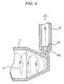
Fig. 4 is a longitudinal sectional view showing a modification of a part of the embodiment of the blood measuring apparatus of the invention. -
Fig. 5 is a schematic diagram illustrating a related-art blood measuring apparatus. - Hereinafter, an embodiment of the blood measuring apparatus of the invention will be described with reference to the accompanying drawings. In the figures, the identical components are denoted by the same reference numerals, and duplicate description will be omitted.
Fig. 1 shows a block diagram of the embodiment of the blood measuring apparatus. The blood measuring apparatus includes afirst chamber 11 and asecond chamber 12. Thefirst chamber 11 and thesecond chamber 12 have a cylindrical (true cylindrical or elliptical cylindrical) shape in which the axis coincides with the lateral direction in the figure. Thesecond chamber 12 is formed into a tapered shape in which the diameter is gradually reduced as advancing from a lateral approximately middle portion toward a right end portion. - A
boundary wall 13 is vertically disposed between thefirst chamber 11 and thesecond chamber 12. Anaperture 14 is formed in a middle portion of theboundary wall 13, and thefirst chamber 11 and thesecond chamber 12 communicate with each other through theaperture 14. - The
first chamber 11 is connected to a diluted blood producing/supplyingsection 21. The diluted blood producing/supplyingsection 21 takes in sample blood by suction, dilutes the blood with a diluting solution (physiological saline or the like) to produce diluted blood, and supplies the diluted blood to thefirst chamber 11 through apipe 22. Avalve 23 is disposed in thepipe 22. - The
second chamber 12 is connected to a dilutingsolution supplying section 25 through apipe 24 in which avalve 15 is disposed. The dilutingsolution supplying section 25 stores the diluting solution. As shown inFigs. 2 and3 , thepipe 24 is coupled with afitting portion 27 which is disposed in the side wall of thesecond chamber 12. Aflow path 27a in thefitting portion 27 extends toward the inner wall on the side of thesecond chamber 12 adjacent to the peripheral edge of theboundary wall 13. - The diluting
solution supplying section 25 supplies the diluting solution by applying a predetermined pressure thereon. The supplied diluting solution flows in along the inner wall on the side of thesecond chamber 12 adjacent to the peripheral edge of theboundary wall 13 through theflow path 27a, and causes a swirling flow S to be produced in a situation where thesecond chamber 12 is filled with the diluting solution. In this way, the dilutingsolution supplying section 25 and theflow path 27a in thefitting portion 27 function as a diluting solution supplying unit which supplies the diluting solution along the inner wall on the side of thesecond chamber 12 adjacent to the peripheral edge of theboundary wall 13, thereby generating a swirling flow. - A
fitting portion 28 which is straightly projected to the outside is disposed in an end portion of thesecond chamber 12 which is opposed to theboundary wall 13. Anoutlet 28a is formed in the fitting portion. Thefitting portion 28 is connected to asolution sucking section 30 which constitutes a sucking unit, through apipe 32 in which avalve 31 is disposed. - The
solution sucking section 30 is configured by a suction pump and the like to suck the solution in thesecond chamber 12. Therefore, blood cells in the diluted blood which flows out from theaperture 14 to the side of thesecond chamber 12 are sucked into thesolution sucking section 30 with maintaining a state where the blood cells are collected in the swirl center by the swirling flow that is produced as described above, and without being dispersed about the periphery and causing recirculation. The sucked solution is stored in a waste fluid section which is connected to thesolution sucking section 30. -
Fig. 4 shows a modification of thefitting portion 28. In an end portion of thesecond chamber 12 which is opposed to theboundary wall 13, thefitting portion 28 is disposed to be upward projected in perpendicular to the wall of the end portion. The projection direction of thefitting portion 28 is not particularly limited. - A
waste fluid section 35 is connected to thefirst chamber 11 through apipe 34 in which avalve 36 is disposed. Thewaste fluid section 35 is configured by a tank which takes in the diluted blood in thefirst chamber 11, and which stores the diluted blood. - A first electrode 41 is disposed in the
first chamber 11, and asecond electrode 42 is disposed in thesecond chamber 12. The first electrode 41 and thesecond electrode 42 are opposed to each other across theaperture 14. - The first electrode 41 and the
second electrode 42 are connected to acontroller 50. Thecontroller 50 is connected to anoperation outputting section 51 having an outputting portion which displays or prints characters and the like, and an operating portion in which keys are disposed. Thecontroller 50 controls the openings and closings of all the above-described valves, and functions as a measuring unit which sets a state where the diluted blood is contained in thefirst chamber 11, and the diluting solution is contained in thesecond chamber 12, and which causes a minute current to flow between the first andsecond electrodes 41 and 42 to perform a blood measurement. - The
controller 50 captures a resistance change due to blood cells which are in the diluted blood, which flow from thefirst chamber 11 to thesecond chamber 12 through theaperture 14 and which exist between the first andsecond electrodes 41 and 42, as a change in potential, and performs a blood cell counting based on the change in potential. A result of the measurement is output from theoperation outputting section 51. - During the measurement, the
controller 50 opens thevalve 23 to supply the diluted blood from the diluted blood producing/supplyingsection 21, thereby controlling the diluted blood so as to flow from thefirst chamber 11 to thesecond chamber 12 through theaperture 14, and also opens thevalve 15 to eject the diluting solution from the dilutingsolution supplying section 25 toward the inner wall on the side of thesecond chamber 12 adjacent to the peripheral edge of theboundary wall 13, through theflow path 27a in thefitting portion 27, thereby generating the swirling flow. - The swirling flow functions so as to collect the diluted blood which has flown to the side of the
second chamber 12 through theaperture 14, toward the swirl center. At this time, thecontroller 50 opens thevalve 31. Therefore, thesolution sucking section 30 sucks the solution in thesecond chamber 12, and hence the diluted blood which is collected to the swirl center by the swirling flow is sucked into thesolution sucking section 30 through thefitting portion 28 with maintaining a state where the diluted blood is collected in the swirl center. Consequently, the diluted blood which has flown out toward thesecond chamber 12 through theaperture 14 is formed into one stream which is partly slightly curved, and then directed toward thesolution sucking section 30. - The process by the blood measuring apparatus of the embodiment is performed as described above. Therefore, blood cells can be prevented from recirculating to the sensing region, and an adequate measurement can be performed. Because of the swirling flow, air bubbles hardly adhere to the sensing region of the
boundary wall 13, so that noises can be prevented from being produced, and a correct measurement can be performed. - According to an aspect of the invention, since the diluting solution is supplied along the inner wall on the side of the second chamber adjacent to the peripheral edge of the boundary wall, thereby causing a swirling flow, blood cells are surrounded by the swirling flow and are not dispersed. Since the diluting solution is sucked from the wall portion of the second chamber which is opposed to the aperture, the diluting solution is sucked in the sucking direction while the diluted blood is collected toward the swirl center by the swirling flow, whereby blood cells in the diluted blood are prevented from recirculating to the sensing region, so that a clean diluting solution always flows in the vicinity of the aperture. Therefore, it is possible to perform a correct measurement. Because of the swirling flow, moreover, air bubbles hardly adhere to the sensing region of the boundary wall. Therefore, noises can be prevented from being produced, and a correct measurement can be performed.
- According to an aspect of the invention, since the second chamber has a cylindrical shape, the supplied diluting solution smoothly circulates along the circumferential wall of the cylinder, and the swirling flow can be adequately generated. Furthermore, the suction portion for the diluting solution has a diameter which is smaller than that of the boundary wall portion. Therefore, the diluted blood which is collected into the swirl center by the swirling flow is sucked while being accelerated.
- According to an aspect of the invention, since the diameter of the second chamber is gradually reduced as advancing from the predetermined portion toward the suction portion for the diluting solution. Therefore, the diluted blood which is collected into the swirl center by the swirling flow is sucked while being accelerated, and a correct measurement can be performed.
Claims (4)
- A blood measuring apparatus comprising:a first chamber which includes a first wall provided with an aperture and in which diluted blood is contained;a second chamber which includes the first wall, a second wall opposed to the first wall and a peripheral wall and in which diluting solution is contained, the first and second chambers communicating with each other through the aperture;first and second electrodes which are disposed in the first and second chambers, respectively;a measuring unit which performs a blood measurement by causing a current to flow between the first and second electrodes;a diluting solution supplying unit which supplies diluting solution along a part of the peripheral wall which is adjacent to a peripheral edge of the first wall; anda sucking unit which sucks the diluting solution from the second wall.
- The blood measuring apparatus according to claim 1, wherein
the second chamber has a cylindrical shape,
the sucking unit sucks the diluting solution from a suction portion of the second wall, and
a diameter of the suction portion of the second wall is smaller than a diameter of the first wall. - The blood measuring apparatus according to claim 2, wherein a diameter of the peripheral wall is gradually reduced as advancing from a predetermined portion toward the suction portion.
- The blood measuring apparatus according to claim 1, wherein the diluting solution supplying unit supplies the diluting solution to generate a swirling flow.
Applications Claiming Priority (1)
| Application Number | Priority Date | Filing Date | Title |
|---|---|---|---|
| JP2010276908A JP5456653B2 (en) | 2010-12-13 | 2010-12-13 | Blood measuring device |
Publications (3)
| Publication Number | Publication Date |
|---|---|
| EP2463655A2 true EP2463655A2 (en) | 2012-06-13 |
| EP2463655A3 EP2463655A3 (en) | 2013-01-23 |
| EP2463655B1 EP2463655B1 (en) | 2016-03-02 |
Family
ID=45098948
Family Applications (1)
| Application Number | Title | Priority Date | Filing Date |
|---|---|---|---|
| EP11193026.9A Active EP2463655B1 (en) | 2010-12-13 | 2011-12-12 | Blood measuring apparatus |
Country Status (4)
| Country | Link |
|---|---|
| US (1) | US9279757B2 (en) |
| EP (1) | EP2463655B1 (en) |
| JP (1) | JP5456653B2 (en) |
| CN (1) | CN102564926B (en) |
Cited By (2)
| Publication number | Priority date | Publication date | Assignee | Title |
|---|---|---|---|---|
| EP2829862A1 (en) * | 2013-07-22 | 2015-01-28 | Nihon Kohden Corporation | Blood measuring apparatus |
| CN104619421A (en) * | 2012-06-22 | 2015-05-13 | 生物辐射实验室股份有限公司 | Condensed geometry nozzle for flow cytometry |
Families Citing this family (4)
| Publication number | Priority date | Publication date | Assignee | Title |
|---|---|---|---|---|
| US10768090B2 (en) * | 2016-12-15 | 2020-09-08 | Horiba, Ltd. | Particle counting apparatus |
| CN113917165A (en) * | 2020-07-10 | 2022-01-11 | 深圳市帝迈生物技术有限公司 | POCT sample analyzer and detection method thereof |
| KR102514030B1 (en) * | 2021-03-31 | 2023-03-24 | 고려대학교 산학협력단 | Device for single cell analysis using micropore |
| CN113702270A (en) * | 2021-11-01 | 2021-11-26 | 碧兴物联科技(深圳)股份有限公司 | Aerosol sheath flow detection structure based on Venturi effect |
Citations (1)
| Publication number | Priority date | Publication date | Assignee | Title |
|---|---|---|---|---|
| JPS61159134A (en) | 1984-12-29 | 1986-07-18 | Toa Medical Electronics Co Ltd | Particle detecting device |
Family Cites Families (23)
| Publication number | Priority date | Publication date | Assignee | Title |
|---|---|---|---|---|
| US3739258A (en) * | 1971-08-20 | 1973-06-12 | Iit Res Inst | Method and apparatus for detecting and sizing microscopic particles |
| DE2644584A1 (en) * | 1976-10-02 | 1978-04-06 | Klauschenz & Perrot | DEVICE FOR DIALYZING THE BLOOD OF A PATIENT |
| DE2750447C2 (en) * | 1977-11-11 | 1986-04-17 | Max-Planck-Gesellschaft zur Förderung der Wissenschaften e.V., 3400 Göttingen | Device for measuring certain properties of particles suspended in a particle suspension |
| CA1159356A (en) * | 1979-10-25 | 1983-12-27 | Kurt Skoog | Method and device for producing microdroplets of fluid |
| DE3437519A1 (en) * | 1983-10-14 | 1985-04-25 | Sequoia Turner Corp | Method and apparatus for analysing particulate material |
| US4710021A (en) | 1983-10-14 | 1987-12-01 | Sequoia-Turner Corporation | Particulate matter analyzing apparatus and method |
| JP2815435B2 (en) | 1989-12-22 | 1998-10-27 | 株式会社日立製作所 | Particle analyzer and blood cell counter |
| USRE36074E (en) * | 1990-11-30 | 1999-02-02 | Toa Medical Electronics Co., Ltd. | Particle detector and particle detecting apparatus having the detector |
| JPH07119757B2 (en) * | 1991-03-31 | 1995-12-20 | 日本光電工業株式会社 | Blood cell counter |
| SE507956C2 (en) * | 1996-11-20 | 1998-08-03 | Medonic Ab | Dilution and measuring device for particle counting |
| US6175227B1 (en) | 1997-07-03 | 2001-01-16 | Coulter International Corp. | Potential-sensing method and apparatus for sensing and characterizing particles by the Coulter principle |
| US6111398A (en) | 1997-07-03 | 2000-08-29 | Coulter International Corp. | Method and apparatus for sensing and characterizing particles |
| JP3888804B2 (en) * | 1999-07-16 | 2007-03-07 | シスメックス株式会社 | Particle measuring device |
| ATE443252T1 (en) * | 2001-11-30 | 2009-10-15 | Sysmex Corp | PARTICLE ANALYZER |
| FI116774B (en) * | 2004-01-08 | 2006-02-28 | Dekati Oy | Method and apparatus for increasing the size of small particles |
| CN101165485B (en) * | 2006-10-18 | 2012-09-19 | 深圳迈瑞生物医疗电子股份有限公司 | Blood cell detector and its micropore sensor assembly |
| US7656146B2 (en) | 2006-11-02 | 2010-02-02 | Shenzhen Mindray Bio-Medical Electronics Co., Ltd. | Particle analyzer based on sheath flow impedance method |
| CN101173887B (en) | 2006-11-02 | 2011-04-06 | 深圳迈瑞生物医疗电子股份有限公司 | Particle analyzer of sheath-flow impedance method |
| CN101266205B (en) | 2007-03-12 | 2011-12-14 | 深圳迈瑞生物医疗电子股份有限公司 | Method for monitoring blood cell test result reliability |
| JP2009142748A (en) * | 2007-12-13 | 2009-07-02 | Dkk Toa Corp | Filtration apparatus and filtration method |
| JP2010125441A (en) * | 2008-12-01 | 2010-06-10 | Shimadzu Corp | System for producing liquid containing bubble particle |
| JP2014006200A (en) * | 2012-06-26 | 2014-01-16 | Horiba Ltd | Counting method of particles in liquid and counting device |
| JP6208487B2 (en) * | 2013-07-22 | 2017-10-04 | 日本光電工業株式会社 | Blood measuring device |
-
2010
- 2010-12-13 JP JP2010276908A patent/JP5456653B2/en active Active
-
2011
- 2011-12-12 US US13/323,627 patent/US9279757B2/en active Active
- 2011-12-12 EP EP11193026.9A patent/EP2463655B1/en active Active
- 2011-12-13 CN CN201110415456.0A patent/CN102564926B/en active Active
Patent Citations (1)
| Publication number | Priority date | Publication date | Assignee | Title |
|---|---|---|---|---|
| JPS61159134A (en) | 1984-12-29 | 1986-07-18 | Toa Medical Electronics Co Ltd | Particle detecting device |
Cited By (4)
| Publication number | Priority date | Publication date | Assignee | Title |
|---|---|---|---|---|
| CN104619421A (en) * | 2012-06-22 | 2015-05-13 | 生物辐射实验室股份有限公司 | Condensed geometry nozzle for flow cytometry |
| EP2864049A4 (en) * | 2012-06-22 | 2016-01-20 | Bio Rad Laboratories | CONDENSED GEOMETRY NOZZLE FOR FLOW CYTOMETRY |
| EP2829862A1 (en) * | 2013-07-22 | 2015-01-28 | Nihon Kohden Corporation | Blood measuring apparatus |
| US9823173B2 (en) | 2013-07-22 | 2017-11-21 | Nihon Kohden Corporation | Blood measuring apparatus |
Also Published As
| Publication number | Publication date |
|---|---|
| CN102564926B (en) | 2016-12-07 |
| EP2463655B1 (en) | 2016-03-02 |
| JP5456653B2 (en) | 2014-04-02 |
| US20120146619A1 (en) | 2012-06-14 |
| CN102564926A (en) | 2012-07-11 |
| US9279757B2 (en) | 2016-03-08 |
| JP2012127680A (en) | 2012-07-05 |
| EP2463655A3 (en) | 2013-01-23 |
Similar Documents
| Publication | Publication Date | Title |
|---|---|---|
| US9279757B2 (en) | Blood measuring apparatus | |
| US9550156B2 (en) | Generation apparatus for dissolving gas in liquid and fluid nozzle | |
| CN104251912B (en) | The method for detecting abnormality of sample processing device and sample processing device | |
| JP6134402B1 (en) | Biological sample imaging apparatus and biological sample imaging method | |
| JP6124285B2 (en) | Circulating cancer cell trap | |
| EP3078971B1 (en) | Urine sample analyzer and urine sample dispensing method | |
| CN207036844U (en) | Sample analyser | |
| CN105264370B (en) | The measuring method of the sample injection device of flow cytometer showed equipment, flow cytometer showed equipment and hemoglobin components | |
| CN106353522B (en) | Integrated sampling needle is filtered for the mixing of in-vitro diagnosis medical instrument | |
| CN108653854A (en) | A kind of pediatrician's paediatrics negative pressure gastric lavage device | |
| EP2829862B1 (en) | Blood measuring apparatus | |
| SE520622C2 (en) | Method and apparatus for measuring concentrations | |
| EP3599456A1 (en) | Channel unit and microparticle analysis device | |
| CN213398557U (en) | Detection device and blood analyzer | |
| CN205982306U (en) | A mixing filtration integral type sampling needle for external diagnosis medical instrument | |
| JP6688089B2 (en) | Flow cell and particle analyzer | |
| CN204395070U (en) | A kind of phlegm liquit collector preventing sputum suck-back | |
| CN103930779B (en) | The measuring method of the sample injection device of biochemical analysis, streaming biochemical analyser and hemoglobin components | |
| CN109374913B (en) | Liquid path system device and control method | |
| US20140296893A1 (en) | Liquid ejection device and medical apparatus | |
| CN107109332A (en) | cell capture device | |
| EP2463640A2 (en) | Blood measuring apparatus | |
| CN217245787U (en) | Nursing sputum suction device for severe clinical use | |
| CN115127602B (en) | A test device and method for the bubble monitoring function of a three-channel high-pressure syringe | |
| JP5044462B2 (en) | Sample testing equipment |
Legal Events
| Date | Code | Title | Description |
|---|---|---|---|
| PUAI | Public reference made under article 153(3) epc to a published international application that has entered the european phase |
Free format text: ORIGINAL CODE: 0009012 |
|
| AK | Designated contracting states |
Kind code of ref document: A2 Designated state(s): AL AT BE BG CH CY CZ DE DK EE ES FI FR GB GR HR HU IE IS IT LI LT LU LV MC MK MT NL NO PL PT RO RS SE SI SK SM TR |
|
| AX | Request for extension of the european patent |
Extension state: BA ME |
|
| PUAL | Search report despatched |
Free format text: ORIGINAL CODE: 0009013 |
|
| AK | Designated contracting states |
Kind code of ref document: A3 Designated state(s): AL AT BE BG CH CY CZ DE DK EE ES FI FR GB GR HR HU IE IS IT LI LT LU LV MC MK MT NL NO PL PT RO RS SE SI SK SM TR |
|
| AX | Request for extension of the european patent |
Extension state: BA ME |
|
| RIC1 | Information provided on ipc code assigned before grant |
Ipc: G01N 27/07 20060101ALI20121218BHEP Ipc: G01N 15/12 20060101ALI20121218BHEP Ipc: G01N 33/49 20060101AFI20121218BHEP |
|
| 17P | Request for examination filed |
Effective date: 20130624 |
|
| RBV | Designated contracting states (corrected) |
Designated state(s): AL AT BE BG CH CY CZ DE DK EE ES FI FR GB GR HR HU IE IS IT LI LT LU LV MC MK MT NL NO PL PT RO RS SE SI SK SM TR |
|
| 17Q | First examination report despatched |
Effective date: 20140912 |
|
| GRAP | Despatch of communication of intention to grant a patent |
Free format text: ORIGINAL CODE: EPIDOSNIGR1 |
|
| INTG | Intention to grant announced |
Effective date: 20150907 |
|
| GRAS | Grant fee paid |
Free format text: ORIGINAL CODE: EPIDOSNIGR3 |
|
| GRAA | (expected) grant |
Free format text: ORIGINAL CODE: 0009210 |
|
| AK | Designated contracting states |
Kind code of ref document: B1 Designated state(s): AL AT BE BG CH CY CZ DE DK EE ES FI FR GB GR HR HU IE IS IT LI LT LU LV MC MK MT NL NO PL PT RO RS SE SI SK SM TR |
|
| REG | Reference to a national code |
Ref country code: GB Ref legal event code: FG4D |
|
| REG | Reference to a national code |
Ref country code: AT Ref legal event code: REF Ref document number: 778394 Country of ref document: AT Kind code of ref document: T Effective date: 20160315 Ref country code: CH Ref legal event code: EP |
|
| REG | Reference to a national code |
Ref country code: IE Ref legal event code: FG4D |
|
| REG | Reference to a national code |
Ref country code: DE Ref legal event code: R096 Ref document number: 602011023588 Country of ref document: DE |
|
| REG | Reference to a national code |
Ref country code: NL Ref legal event code: MP Effective date: 20160302 |
|
| REG | Reference to a national code |
Ref country code: LT Ref legal event code: MG4D |
|
| REG | Reference to a national code |
Ref country code: AT Ref legal event code: MK05 Ref document number: 778394 Country of ref document: AT Kind code of ref document: T Effective date: 20160302 |
|
| PG25 | Lapsed in a contracting state [announced via postgrant information from national office to epo] |
Ref country code: NO Free format text: LAPSE BECAUSE OF FAILURE TO SUBMIT A TRANSLATION OF THE DESCRIPTION OR TO PAY THE FEE WITHIN THE PRESCRIBED TIME-LIMIT Effective date: 20160602 Ref country code: GR Free format text: LAPSE BECAUSE OF FAILURE TO SUBMIT A TRANSLATION OF THE DESCRIPTION OR TO PAY THE FEE WITHIN THE PRESCRIBED TIME-LIMIT Effective date: 20160603 Ref country code: FI Free format text: LAPSE BECAUSE OF FAILURE TO SUBMIT A TRANSLATION OF THE DESCRIPTION OR TO PAY THE FEE WITHIN THE PRESCRIBED TIME-LIMIT Effective date: 20160302 Ref country code: HR Free format text: LAPSE BECAUSE OF FAILURE TO SUBMIT A TRANSLATION OF THE DESCRIPTION OR TO PAY THE FEE WITHIN THE PRESCRIBED TIME-LIMIT Effective date: 20160302 Ref country code: ES Free format text: LAPSE BECAUSE OF FAILURE TO SUBMIT A TRANSLATION OF THE DESCRIPTION OR TO PAY THE FEE WITHIN THE PRESCRIBED TIME-LIMIT Effective date: 20160302 |
|
| PG25 | Lapsed in a contracting state [announced via postgrant information from national office to epo] |
Ref country code: AT Free format text: LAPSE BECAUSE OF FAILURE TO SUBMIT A TRANSLATION OF THE DESCRIPTION OR TO PAY THE FEE WITHIN THE PRESCRIBED TIME-LIMIT Effective date: 20160302 Ref country code: RS Free format text: LAPSE BECAUSE OF FAILURE TO SUBMIT A TRANSLATION OF THE DESCRIPTION OR TO PAY THE FEE WITHIN THE PRESCRIBED TIME-LIMIT Effective date: 20160302 Ref country code: NL Free format text: LAPSE BECAUSE OF FAILURE TO SUBMIT A TRANSLATION OF THE DESCRIPTION OR TO PAY THE FEE WITHIN THE PRESCRIBED TIME-LIMIT Effective date: 20160302 Ref country code: LT Free format text: LAPSE BECAUSE OF FAILURE TO SUBMIT A TRANSLATION OF THE DESCRIPTION OR TO PAY THE FEE WITHIN THE PRESCRIBED TIME-LIMIT Effective date: 20160302 Ref country code: PL Free format text: LAPSE BECAUSE OF FAILURE TO SUBMIT A TRANSLATION OF THE DESCRIPTION OR TO PAY THE FEE WITHIN THE PRESCRIBED TIME-LIMIT Effective date: 20160302 Ref country code: SE Free format text: LAPSE BECAUSE OF FAILURE TO SUBMIT A TRANSLATION OF THE DESCRIPTION OR TO PAY THE FEE WITHIN THE PRESCRIBED TIME-LIMIT Effective date: 20160302 Ref country code: LV Free format text: LAPSE BECAUSE OF FAILURE TO SUBMIT A TRANSLATION OF THE DESCRIPTION OR TO PAY THE FEE WITHIN THE PRESCRIBED TIME-LIMIT Effective date: 20160302 |
|
| PG25 | Lapsed in a contracting state [announced via postgrant information from national office to epo] |
Ref country code: IS Free format text: LAPSE BECAUSE OF FAILURE TO SUBMIT A TRANSLATION OF THE DESCRIPTION OR TO PAY THE FEE WITHIN THE PRESCRIBED TIME-LIMIT Effective date: 20160702 Ref country code: EE Free format text: LAPSE BECAUSE OF FAILURE TO SUBMIT A TRANSLATION OF THE DESCRIPTION OR TO PAY THE FEE WITHIN THE PRESCRIBED TIME-LIMIT Effective date: 20160302 |
|
| REG | Reference to a national code |
Ref country code: FR Ref legal event code: PLFP Year of fee payment: 6 |
|
| PG25 | Lapsed in a contracting state [announced via postgrant information from national office to epo] |
Ref country code: RO Free format text: LAPSE BECAUSE OF FAILURE TO SUBMIT A TRANSLATION OF THE DESCRIPTION OR TO PAY THE FEE WITHIN THE PRESCRIBED TIME-LIMIT Effective date: 20160302 Ref country code: CZ Free format text: LAPSE BECAUSE OF FAILURE TO SUBMIT A TRANSLATION OF THE DESCRIPTION OR TO PAY THE FEE WITHIN THE PRESCRIBED TIME-LIMIT Effective date: 20160302 Ref country code: PT Free format text: LAPSE BECAUSE OF FAILURE TO SUBMIT A TRANSLATION OF THE DESCRIPTION OR TO PAY THE FEE WITHIN THE PRESCRIBED TIME-LIMIT Effective date: 20160704 Ref country code: SK Free format text: LAPSE BECAUSE OF FAILURE TO SUBMIT A TRANSLATION OF THE DESCRIPTION OR TO PAY THE FEE WITHIN THE PRESCRIBED TIME-LIMIT Effective date: 20160302 Ref country code: SM Free format text: LAPSE BECAUSE OF FAILURE TO SUBMIT A TRANSLATION OF THE DESCRIPTION OR TO PAY THE FEE WITHIN THE PRESCRIBED TIME-LIMIT Effective date: 20160302 |
|
| REG | Reference to a national code |
Ref country code: DE Ref legal event code: R097 Ref document number: 602011023588 Country of ref document: DE |
|
| PG25 | Lapsed in a contracting state [announced via postgrant information from national office to epo] |
Ref country code: IT Free format text: LAPSE BECAUSE OF FAILURE TO SUBMIT A TRANSLATION OF THE DESCRIPTION OR TO PAY THE FEE WITHIN THE PRESCRIBED TIME-LIMIT Effective date: 20160302 Ref country code: BE Free format text: LAPSE BECAUSE OF FAILURE TO SUBMIT A TRANSLATION OF THE DESCRIPTION OR TO PAY THE FEE WITHIN THE PRESCRIBED TIME-LIMIT Effective date: 20160302 |
|
| PLBE | No opposition filed within time limit |
Free format text: ORIGINAL CODE: 0009261 |
|
| STAA | Information on the status of an ep patent application or granted ep patent |
Free format text: STATUS: NO OPPOSITION FILED WITHIN TIME LIMIT |
|
| PG25 | Lapsed in a contracting state [announced via postgrant information from national office to epo] |
Ref country code: DK Free format text: LAPSE BECAUSE OF FAILURE TO SUBMIT A TRANSLATION OF THE DESCRIPTION OR TO PAY THE FEE WITHIN THE PRESCRIBED TIME-LIMIT Effective date: 20160302 |
|
| 26N | No opposition filed |
Effective date: 20161205 |
|
| PG25 | Lapsed in a contracting state [announced via postgrant information from national office to epo] |
Ref country code: BG Free format text: LAPSE BECAUSE OF FAILURE TO SUBMIT A TRANSLATION OF THE DESCRIPTION OR TO PAY THE FEE WITHIN THE PRESCRIBED TIME-LIMIT Effective date: 20160602 Ref country code: SI Free format text: LAPSE BECAUSE OF FAILURE TO SUBMIT A TRANSLATION OF THE DESCRIPTION OR TO PAY THE FEE WITHIN THE PRESCRIBED TIME-LIMIT Effective date: 20160302 |
|
| REG | Reference to a national code |
Ref country code: CH Ref legal event code: PL |
|
| GBPC | Gb: european patent ceased through non-payment of renewal fee |
Effective date: 20161212 |
|
| PG25 | Lapsed in a contracting state [announced via postgrant information from national office to epo] |
Ref country code: MC Free format text: LAPSE BECAUSE OF FAILURE TO SUBMIT A TRANSLATION OF THE DESCRIPTION OR TO PAY THE FEE WITHIN THE PRESCRIBED TIME-LIMIT Effective date: 20160302 |
|
| REG | Reference to a national code |
Ref country code: IE Ref legal event code: MM4A |
|
| PG25 | Lapsed in a contracting state [announced via postgrant information from national office to epo] |
Ref country code: CH Free format text: LAPSE BECAUSE OF NON-PAYMENT OF DUE FEES Effective date: 20161231 Ref country code: LU Free format text: LAPSE BECAUSE OF NON-PAYMENT OF DUE FEES Effective date: 20161212 Ref country code: LI Free format text: LAPSE BECAUSE OF NON-PAYMENT OF DUE FEES Effective date: 20161231 |
|
| REG | Reference to a national code |
Ref country code: FR Ref legal event code: PLFP Year of fee payment: 7 |
|
| PG25 | Lapsed in a contracting state [announced via postgrant information from national office to epo] |
Ref country code: GB Free format text: LAPSE BECAUSE OF NON-PAYMENT OF DUE FEES Effective date: 20161212 Ref country code: IE Free format text: LAPSE BECAUSE OF NON-PAYMENT OF DUE FEES Effective date: 20161212 |
|
| PG25 | Lapsed in a contracting state [announced via postgrant information from national office to epo] |
Ref country code: HU Free format text: LAPSE BECAUSE OF FAILURE TO SUBMIT A TRANSLATION OF THE DESCRIPTION OR TO PAY THE FEE WITHIN THE PRESCRIBED TIME-LIMIT; INVALID AB INITIO Effective date: 20111212 Ref country code: CY Free format text: LAPSE BECAUSE OF FAILURE TO SUBMIT A TRANSLATION OF THE DESCRIPTION OR TO PAY THE FEE WITHIN THE PRESCRIBED TIME-LIMIT Effective date: 20160302 |
|
| PG25 | Lapsed in a contracting state [announced via postgrant information from national office to epo] |
Ref country code: TR Free format text: LAPSE BECAUSE OF FAILURE TO SUBMIT A TRANSLATION OF THE DESCRIPTION OR TO PAY THE FEE WITHIN THE PRESCRIBED TIME-LIMIT Effective date: 20160302 Ref country code: MK Free format text: LAPSE BECAUSE OF FAILURE TO SUBMIT A TRANSLATION OF THE DESCRIPTION OR TO PAY THE FEE WITHIN THE PRESCRIBED TIME-LIMIT Effective date: 20160302 |
|
| PG25 | Lapsed in a contracting state [announced via postgrant information from national office to epo] |
Ref country code: MT Free format text: LAPSE BECAUSE OF NON-PAYMENT OF DUE FEES Effective date: 20161212 |
|
| PG25 | Lapsed in a contracting state [announced via postgrant information from national office to epo] |
Ref country code: AL Free format text: LAPSE BECAUSE OF FAILURE TO SUBMIT A TRANSLATION OF THE DESCRIPTION OR TO PAY THE FEE WITHIN THE PRESCRIBED TIME-LIMIT Effective date: 20160302 |
|
| PGFP | Annual fee paid to national office [announced via postgrant information from national office to epo] |
Ref country code: DE Payment date: 20251028 Year of fee payment: 15 |
|
| PGFP | Annual fee paid to national office [announced via postgrant information from national office to epo] |
Ref country code: FR Payment date: 20251110 Year of fee payment: 15 |