EP2463578B1 - Device for securing fixtures - Google Patents
Device for securing fixtures Download PDFInfo
- Publication number
- EP2463578B1 EP2463578B1 EP20100194410 EP10194410A EP2463578B1 EP 2463578 B1 EP2463578 B1 EP 2463578B1 EP 20100194410 EP20100194410 EP 20100194410 EP 10194410 A EP10194410 A EP 10194410A EP 2463578 B1 EP2463578 B1 EP 2463578B1
- Authority
- EP
- European Patent Office
- Prior art keywords
- fixture
- opening
- securing
- lighting fixture
- elastic member
- Prior art date
- Legal status (The legal status is an assumption and is not a legal conclusion. Google has not performed a legal analysis and makes no representation as to the accuracy of the status listed.)
- Not-in-force
Links
- 239000013013 elastic material Substances 0.000 claims description 4
- 239000000463 material Substances 0.000 description 5
- 230000000284 resting effect Effects 0.000 description 4
- 229920003023 plastic Polymers 0.000 description 2
- 239000004033 plastic Substances 0.000 description 2
- 229910000831 Steel Inorganic materials 0.000 description 1
- 238000003780 insertion Methods 0.000 description 1
- 230000037431 insertion Effects 0.000 description 1
- 239000002184 metal Substances 0.000 description 1
- 238000000034 method Methods 0.000 description 1
- 239000012858 resilient material Substances 0.000 description 1
- 230000000717 retained effect Effects 0.000 description 1
- 239000010959 steel Substances 0.000 description 1
Images

Classifications
-
- F—MECHANICAL ENGINEERING; LIGHTING; HEATING; WEAPONS; BLASTING
- F21—LIGHTING
- F21S—NON-PORTABLE LIGHTING DEVICES; SYSTEMS THEREOF; VEHICLE LIGHTING DEVICES SPECIALLY ADAPTED FOR VEHICLE EXTERIORS
- F21S8/00—Lighting devices intended for fixed installation
- F21S8/02—Lighting devices intended for fixed installation of recess-mounted type, e.g. downlighters
- F21S8/026—Lighting devices intended for fixed installation of recess-mounted type, e.g. downlighters intended to be recessed in a ceiling or like overhead structure, e.g. suspended ceiling
-
- F—MECHANICAL ENGINEERING; LIGHTING; HEATING; WEAPONS; BLASTING
- F21—LIGHTING
- F21V—FUNCTIONAL FEATURES OR DETAILS OF LIGHTING DEVICES OR SYSTEMS THEREOF; STRUCTURAL COMBINATIONS OF LIGHTING DEVICES WITH OTHER ARTICLES, NOT OTHERWISE PROVIDED FOR
- F21V21/00—Supporting, suspending, or attaching arrangements for lighting devices; Hand grips
- F21V21/02—Wall, ceiling, or floor bases; Fixing pendants or arms to the bases
- F21V21/04—Recessed bases
- F21V21/047—Mounting arrangements with fastening means engaging the inner surface of a hole in a ceiling or wall, e.g. for solid walls or for blind holes
-
- F—MECHANICAL ENGINEERING; LIGHTING; HEATING; WEAPONS; BLASTING
- F21—LIGHTING
- F21S—NON-PORTABLE LIGHTING DEVICES; SYSTEMS THEREOF; VEHICLE LIGHTING DEVICES SPECIALLY ADAPTED FOR VEHICLE EXTERIORS
- F21S8/00—Lighting devices intended for fixed installation
- F21S8/02—Lighting devices intended for fixed installation of recess-mounted type, e.g. downlighters
- F21S8/024—Lighting devices intended for fixed installation of recess-mounted type, e.g. downlighters intended to be recessed in a wall or like vertical structure, e.g. building facade
Definitions
- the present invention refers to a device for securing fixtures, particularly for lighting fixtures.
- Said securing systems substantially consist of a plurality of arms that are deflected by elastic means interacting with the structure to which the lighting fixture is fixed.
- These securing systems comprise a plurality of elastically deflected radial arms, which are attached to the lighting fixture at one of their ends. Each arm is elastically deflected by a spring, which tends to radially move the free end of the arm out from the lighting fixture.
- the lighting fixture To secure the lighting fixture to the false ceiling, the lighting fixture is inserted into an opening in the false ceiling. Before inserting the lighting fixture into the opening, it is necessary to bend or force the arms inward against the resilient action of the springs which tend to move the arms radially outward. This must be done by hand, and the user must hold the arms folded while inserting the lighting fixture into the opening.
- the user releases the arms, which are deflected radially outwards by the respective springs.
- the arms press against the wall of the opening as they are outwardly deflected.
- the arms pass through the false ceiling panel and stop pressing the walls of the opening and extend completely, now resting on the upper surface of the false ceiling.
- the lighting fixture is secured to the false ceiling by the action of the arms.
- the free ends of the arms damage the inside walls of the opening in the false ceiling when the lighting system is being inserted into the opening, since the deflecting force of the arms can be strong and the material with which the false ceiling is made of is usually weak.
- US 5068772 shows a fixture according to the preamble of claim 1.
- the aim of the present invention is to solve the drawbacks of the devices known in the art by providing the fixture and the device for securing the fixture of claim 1.
- a fixture securing device that allows the easy and smooth securing of the fixture on a panel member by avoiding having to make considerable efforts and possible damage to the panel member is provided.
- the curved shape of the securing elastic member facilitates the insertion of the fixture in an opening of the panel member, said elastic member being compressed by the walls of this opening until the element passes through the panel and returns to its original resting form.
- the action of the walls of the opening on the curved portion is 'tangential' and continuous. This continuous deformation of the elastic member prevents sudden or violent movements of the elastic member that may damage the panel member, as happened in the prior art devices. Also, the curved configuration of the elastic member prevents users from having to hold said elastic member with their hands before inserting the fixture into the opening.
- the outer curved portion comprises a band of elastic material.
- the band of elastic material may be a flat metal or plastic band being elastic and resistant enough to fulfil its function.
- the two ends of the outer curved portion are connected the one to the other by the outer curved portion itself and by another element, so that the relative position between these ends is always fixed.
- This other element comprises an additional segment of the elastic member or part of the fixture itself. That is, the elastic member and/or the outer curved portion comprise or form part of a closed body as a resiliently deformable loop without ends.
- a line joining the two ends of the outer curved portion is substantially perpendicular to the plane of the opening when inserting the fixture into the opening.
- the elastic member is substantially D-shaped.
- the fixture is a lighting fixture.
- fixture means in a particularly preferred way a lighting fixture, although this term also includes other devices such as speakers, cameras, detectors, or the like.
- FIG. 1 shows a lighting fixture 1 and a pair of securing devices 2 according to the present invention.
- Each securing device 2 comprises an elastic member 3 and an upper support 4.
- the elastic member 3 comprises a D-shaped body made of a band of flexible material and includes a curved outer portion 5 and a straight segment 6.
- the curved outer portion 5 comprises an upper end 5a and a lower end 5b, which are connected by the curved outer portion itself 5 and the straight segment 6.
- Each securing device 2 is attached to a respective vertical extension 7 located on diametrically opposite sides of the lighting fixture 1 by screws 8 passing through a hole in each upper support 4 and are screwed to a threaded hole located on top of each vertical extension 7.
- each securing device 2 When each securing device 2 is mounted in the lighting fixture 1, the same is arranged as shown in figures 2-4 , with the straight segment 6 and the ends 5a and 5b positioned adjacent to each respective vertical extension 7.
- the assembly of the securing device 2 in the lighting fixture 1 can be carried out in any other known way.
- Figures 2-4 further show the assembly procedure of the lighting fixture 1 in a panel member 10, such as a false ceiling.
- the false ceiling 10 comprises a circular opening 11 cut through it wherein the lighting fixture 1 is inserted to mount it on the ceiling 10.
- the lighting fixture 1 with the elastic members 3 mounted on the same ( Figure 2 ) is inserted into the opening 11 by moving it in the direction of its longitudinal axis perpendicularly to the plane of the opening 11 and the false ceiling 10.
- Each curved outer portion 5 is also oriented with its longitudinal extension perpendicular to the plane of the opening 11 and false ceiling 10.
- each elastic member 3 At resting state, the curved outer portion 5 of each elastic member 3 comprises a configuration in which the distance d between the outer surface of both curved outer portions 5 further away from the centre of the lighting device 1 is larger than the diameter D of the opening 11.
- the curved outer portions 5 When starting to insert the lighting fixture 1 in the opening 11, the curved outer portions 5 are compressed towards the centre of the lighting fixture 1 by the inner walls of the opening 11 ( Figure 3 ). The force required to deform and compress the curved outer portions 5 is exerted by the user by pushing up the lighting fixture 1. As the lighting fixture 1 is moved upwards, the length of the curved outer portions 5 adjacent to the inner walls of the opening 11 slides on them and is compressed toward the centre of the lighting fixture 1.
- the majority of the curved outer portions 5 has passed through the opening 11 and is on the opposite side (top side) of the false ceiling 10. Due to the fact that the curved outer portions 5 tends to recover their original shape or resting state (see figure 2 ), they extend outward so that the distance d between the outer surface of both curved outer portions 5 further away from the centre of the lighting device 1 is larger than the diameter D of the opening 11. Therefore, the lighting fixture 1 is retained in the false ceiling 10 by the curved outer portions 5.
- the effort required to remove the lighting fixture 1 will be considerably less than the effort required to perform the same operation in securing devices known in the art using elastically deflected arms.
- the potential damage to the ceiling material when mounting or removing the lighting fixture 1 are minimized or eliminated.
- the elastic member 3 is substantially D-shaped, and the ends 5a, 5b of the curved outer portion 5 are connected together by means of both, the curved outer portion 5 itself and the straight segment 6.
- the ends 5a, 5b may also be connected, for example, through a part of the lighting fixture 1, so that the relative position between both ends 5a, 5b is always fixed.
- the elastic member 3 will be made of a sufficiently elastic and resilient material allowing for its suitable use in the securing device 2 of the present invention.
- a suitable material is steel, although other materials, such as plastics, are possible.
- the present invention is specially designed for use in lighting fixtures. However, its use is also provided for securing other fixtures such as wall speakers, cameras or detectors.
- panel member means any structure in which it is possible to mount a fixture in the manner described above, the element comprising preferably a false ceiling, but can also comprise walls or other structures.
Landscapes
- Engineering & Computer Science (AREA)
- General Engineering & Computer Science (AREA)
- Securing Globes, Refractors, Reflectors Or The Like (AREA)
- Non-Portable Lighting Devices Or Systems Thereof (AREA)
- Clamps And Clips (AREA)
Description
- The present invention refers to a device for securing fixtures, particularly for lighting fixtures.
- Systems for securing lighting fixtures on panelboard structures such as ceilings or walls, particularly false ceilings, are known.
- Said securing systems substantially consist of a plurality of arms that are deflected by elastic means interacting with the structure to which the lighting fixture is fixed.
- Specifically, lighting securing systems that are fixed within an opening in a false ceiling or similar structure are known.
- These securing systems comprise a plurality of elastically deflected radial arms, which are attached to the lighting fixture at one of their ends. Each arm is elastically deflected by a spring, which tends to radially move the free end of the arm out from the lighting fixture.
- To secure the lighting fixture to the false ceiling, the lighting fixture is inserted into an opening in the false ceiling. Before inserting the lighting fixture into the opening, it is necessary to bend or force the arms inward against the resilient action of the springs which tend to move the arms radially outward. This must be done by hand, and the user must hold the arms folded while inserting the lighting fixture into the opening.
- Once the top of the lighting fixture is inserted into the opening of the ceiling, the user releases the arms, which are deflected radially outwards by the respective springs. The arms press against the wall of the opening as they are outwardly deflected.
- Once the lighting fixture is fully inserted into the opening, the arms pass through the false ceiling panel and stop pressing the walls of the opening and extend completely, now resting on the upper surface of the false ceiling. Thus, the lighting fixture is secured to the false ceiling by the action of the arms.
- The drawback of the described systems is that users must hold the resiliently deflected arms with their hands before inserting them into the opening, which makes the assembly operation of the lighting fixture difficult.
- It is also possible that the free ends of the arms damage the inside walls of the opening in the false ceiling when the lighting system is being inserted into the opening, since the deflecting force of the arms can be strong and the material with which the false ceiling is made of is usually weak.
- Finally, the systems described greatly hinder the removal of the lighting fixture, since the user must exert considerable force to overcome the deflecting force exerted by the spring and extract the lighting fixture from the opening. Typically, the user must pull the lighting fixture to move the arms inwardly, which can cause damage to the false ceiling if the operation is not performed carefully.
-
US 5068772 shows a fixture according to the preamble ofclaim 1. - The aim of the present invention is to solve the drawbacks of the devices known in the art by providing the fixture and the device for securing the fixture of
claim 1. - Thanks to these characteristics, a fixture securing device that allows the easy and smooth securing of the fixture on a panel member by avoiding having to make considerable efforts and possible damage to the panel member is provided.
- The curved shape of the securing elastic member facilitates the insertion of the fixture in an opening of the panel member, said elastic member being compressed by the walls of this opening until the element passes through the panel and returns to its original resting form.
- The action of the walls of the opening on the curved portion is 'tangential' and continuous. This continuous deformation of the elastic member prevents sudden or violent movements of the elastic member that may damage the panel member, as happened in the prior art devices. Also, the curved configuration of the elastic member prevents users from having to hold said elastic member with their hands before inserting the fixture into the opening.
- Preferably, the outer curved portion comprises a band of elastic material. The band of elastic material may be a flat metal or plastic band being elastic and resistant enough to fulfil its function.
- As already stated, the two ends of the outer curved portion are connected the one to the other by the outer curved portion itself and by another element, so that the relative position between these ends is always fixed. This other element comprises an additional segment of the elastic member or part of the fixture itself. That is, the elastic member and/or the outer curved portion comprise or form part of a closed body as a resiliently deformable loop without ends.
- Also advantageously, a line joining the two ends of the outer curved portion is substantially perpendicular to the plane of the opening when inserting the fixture into the opening.
- According to an embodiment of the invention, the elastic member is substantially D-shaped.
- Preferably, the fixture is a lighting fixture.
- In the present specification the term fixture means in a particularly preferred way a lighting fixture, although this term also includes other devices such as speakers, cameras, detectors, or the like.
- In order to facilitate the description of all the above previously exposed, some drawings are included in which, schematically and only by way of non restrictive example, a practical case of embodiment of the fixing device according to the invention is represented, wherein:
-
Figure 1 is a perspective view of a lighting device comprising the fixing device of the present invention; -
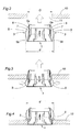
Figures 2 to 4 are representative views showing the assembly of a lighting device on a false ceiling using the fixing device of the present invention. -
Figure 1 shows alighting fixture 1 and a pair of securingdevices 2 according to the present invention. Eachsecuring device 2 comprises anelastic member 3 and anupper support 4. Theelastic member 3 comprises a D-shaped body made of a band of flexible material and includes a curvedouter portion 5 and astraight segment 6. - The curved
outer portion 5 comprises anupper end 5a and alower end 5b, which are connected by the curved outer portion itself 5 and thestraight segment 6. - Each
securing device 2 is attached to a respectivevertical extension 7 located on diametrically opposite sides of thelighting fixture 1 byscrews 8 passing through a hole in eachupper support 4 and are screwed to a threaded hole located on top of eachvertical extension 7. - When each
securing device 2 is mounted in thelighting fixture 1, the same is arranged as shown infigures 2-4 , with thestraight segment 6 and theends vertical extension 7. - The assembly of the securing
device 2 in thelighting fixture 1 can be carried out in any other known way. -
Figures 2-4 further show the assembly procedure of thelighting fixture 1 in apanel member 10, such as a false ceiling. Thefalse ceiling 10 comprises acircular opening 11 cut through it wherein thelighting fixture 1 is inserted to mount it on theceiling 10. - The
lighting fixture 1 with theelastic members 3 mounted on the same (Figure 2 ) is inserted into theopening 11 by moving it in the direction of its longitudinal axis perpendicularly to the plane of theopening 11 and thefalse ceiling 10. Each curvedouter portion 5 is also oriented with its longitudinal extension perpendicular to the plane of the opening 11 andfalse ceiling 10. - At resting state, the curved
outer portion 5 of eachelastic member 3 comprises a configuration in which the distance d between the outer surface of both curvedouter portions 5 further away from the centre of thelighting device 1 is larger than the diameter D of theopening 11. - When starting to insert the
lighting fixture 1 in theopening 11, the curvedouter portions 5 are compressed towards the centre of thelighting fixture 1 by the inner walls of the opening 11 (Figure 3 ). The force required to deform and compress the curvedouter portions 5 is exerted by the user by pushing up thelighting fixture 1. As thelighting fixture 1 is moved upwards, the length of the curvedouter portions 5 adjacent to the inner walls of the opening 11 slides on them and is compressed toward the centre of thelighting fixture 1. - Thanks to the curved shape of the
portions 5, the effort required to insert thelighting fixture 1 and necessary to deform said curvedouter portions 5 is reduced, as the deformation occurs continuously and gradually. - When the
lighting fixture 1 has been fully inserted into the opening 11 (figure 4 ), until its bottom is adjacent to the lower edges of theopening 11, the majority of the curvedouter portions 5 has passed through theopening 11 and is on the opposite side (top side) of thefalse ceiling 10. Due to the fact that the curvedouter portions 5 tends to recover their original shape or resting state (seefigure 2 ), they extend outward so that the distance d between the outer surface of both curvedouter portions 5 further away from the centre of thelighting device 1 is larger than the diameter D of theopening 11. Therefore, thelighting fixture 1 is retained in thefalse ceiling 10 by the curvedouter portions 5. - If the user wishes to remove the
lighting fixture 1 from thefalse ceiling 10, it only need to pull down thelighting fixture 1, so that the curvedouter portions 5 are again distorted and compressed by the inner walls of theopening 11 following the inverse sequence to that described above. - The effort required to remove the
lighting fixture 1 will be considerably less than the effort required to perform the same operation in securing devices known in the art using elastically deflected arms. In addition, due to the smooth and continuous contact between the curvedouter portions 5 and the inner walls of theopening 11, the potential damage to the ceiling material when mounting or removing thelighting fixture 1 are minimized or eliminated. - In the embodiment shown herein, the
elastic member 3 is substantially D-shaped, and theends outer portion 5 are connected together by means of both, the curvedouter portion 5 itself and thestraight segment 6. However, instead of being connected by thestraight segment 6, theends lighting fixture 1, so that the relative position between bothends - The
elastic member 3 will be made of a sufficiently elastic and resilient material allowing for its suitable use in the securingdevice 2 of the present invention. A suitable material is steel, although other materials, such as plastics, are possible. - The present invention is specially designed for use in lighting fixtures. However, its use is also provided for securing other fixtures such as wall speakers, cameras or detectors.
- Finally, in the present invention the term panel member means any structure in which it is possible to mount a fixture in the manner described above, the element comprising preferably a false ceiling, but can also comprise walls or other structures.
Claims (5)
- A fixture (1) and a device (2) for securing the fixture (1), comprising securing means for securing the fixture (1) to an opening (11) on a panel member (10), said securing means including two elastic members (3) associated with the fixture (1), each elastic member (3) including an outer curved portion (5) comprising an expanded rest condition and which is elastically compressed by the opening (11) when inserting the fixture (1) into said opening (11), the outer curved portion (5) recovering its expanded rest condition after passing through the opening (11) and retaining the fixture in the panel member (10), characterized in that the two ends (5a, 5b) of the outer curved portion (5) are connected to each other by the outer curved portion (5) itself and by a straight segment (6) of the elastic member (3), so that the relative position between both ends (5a, 5b) is always fixed, and in that each elastic member (3) is attached to respective vertical extensions (7) located on diametrically opposite sides of the fixture (1), with the straight segment (6) and the ends (5a, 5b) of each elastic member (3) positioned adjacent to each respective vertical extension (7).
- A fixture (1) and a device (2) for securing the fixture (1) according to claim 1, characterized in that the outer curved portion (5) comprises a band of elastic material.
- A fixture (1) and a device (2) for securing the fixture (1) according to any of the preceding claims, characterized in that a line joining the two ends (5a, 5b) of the outer curved portion (5) is substantially perpendicular to the plane of the opening (11) when inserting the fixture (1) into the opening (11).
- A fixture (1) and a device (2) for securing the fixture (1) according to any of the preceding claims, characterized in that the elastic member (3) is substantially D-shaped.
- A fixture (1) and a device (2) for securing the fixture (1) according to any of the preceding claims, characterized in that the fixture is a lighting fixture (1).
Priority Applications (2)
| Application Number | Priority Date | Filing Date | Title |
|---|---|---|---|
| ES10194410.6T ES2487536T3 (en) | 2010-12-09 | 2010-12-09 | Device for attaching accessories |
| EP20100194410 EP2463578B1 (en) | 2010-12-09 | 2010-12-09 | Device for securing fixtures |
Applications Claiming Priority (1)
| Application Number | Priority Date | Filing Date | Title |
|---|---|---|---|
| EP20100194410 EP2463578B1 (en) | 2010-12-09 | 2010-12-09 | Device for securing fixtures |
Publications (2)
| Publication Number | Publication Date |
|---|---|
| EP2463578A1 EP2463578A1 (en) | 2012-06-13 |
| EP2463578B1 true EP2463578B1 (en) | 2014-05-21 |
Family
ID=43430774
Family Applications (1)
| Application Number | Title | Priority Date | Filing Date |
|---|---|---|---|
| EP20100194410 Not-in-force EP2463578B1 (en) | 2010-12-09 | 2010-12-09 | Device for securing fixtures |
Country Status (2)
| Country | Link |
|---|---|
| EP (1) | EP2463578B1 (en) |
| ES (1) | ES2487536T3 (en) |
Families Citing this family (6)
| Publication number | Priority date | Publication date | Assignee | Title |
|---|---|---|---|---|
| US9228723B2 (en) | 2012-03-27 | 2016-01-05 | Abl Ip Holding Llc | Downlight fixtures |
| GB2513191B (en) * | 2013-04-19 | 2019-03-20 | Led Group | A lamp assembly |
| CN107620905B (en) * | 2017-10-14 | 2024-03-22 | 嘉兴日雅光电有限公司 | Novel down lamp |
| JP7005395B2 (en) * | 2018-03-13 | 2022-01-21 | コイズミ照明株式会社 | lighting equipment |
| KR102455596B1 (en) * | 2022-04-01 | 2022-10-17 | 주식회사 엘케이비주얼 | line type lighting instrument |
| NO347917B1 (en) * | 2022-08-16 | 2024-05-13 | Sg Armaturen As | Device and system for fixation of recessed downlights |
Family Cites Families (4)
| Publication number | Priority date | Publication date | Assignee | Title |
|---|---|---|---|---|
| FR81325E (en) * | 1962-01-24 | 1963-09-06 | Ceiling recessed lamp holder | |
| JPS56116204A (en) * | 1980-02-15 | 1981-09-11 | Toshiba Electric Equip | Instrument mounting device |
| US5068772A (en) * | 1990-08-30 | 1991-11-26 | Troy Lighting, Inc. | Recessed lighting fixture |
| DE10014967C2 (en) * | 2000-03-25 | 2002-03-21 | Raymond A & Cie | Fasteners, especially for recessed lights |
-
2010
- 2010-12-09 ES ES10194410.6T patent/ES2487536T3/en active Active
- 2010-12-09 EP EP20100194410 patent/EP2463578B1/en not_active Not-in-force
Also Published As
| Publication number | Publication date |
|---|---|
| EP2463578A1 (en) | 2012-06-13 |
| ES2487536T3 (en) | 2014-08-21 |
Similar Documents
| Publication | Publication Date | Title |
|---|---|---|
| EP2463578A1 (en) | Device for securing fixtures | |
| US8474774B2 (en) | Panel component holder | |
| EP3396235B1 (en) | Downlight fixing structure | |
| CN109891695B (en) | Hanger for mounting multiple cables | |
| US5045984A (en) | Mounting device for releasable securement to a panel | |
| US9310036B1 (en) | Retrofit mounting device for open frame ceiling | |
| EP1845295B1 (en) | Pipe clamp with spring nut | |
| EP2979016B1 (en) | Tube-retaining clip assembly | |
| EP3680532B1 (en) | Plastic pipe clip | |
| EP2608646B1 (en) | Cable arrangement device for cable management arm | |
| EP2707633B1 (en) | Pipe clip | |
| CN113330252A (en) | Mountable device and method | |
| KR20190046476A (en) | Hanger for pipe | |
| US8973216B1 (en) | Grommet | |
| US20210120994A1 (en) | Shower curtain ring | |
| KR20190116488A (en) | Fastening Device and Fastening Assembly | |
| RU2682809C2 (en) | Anchoring device | |
| CN110036228A (en) | Tube hanger | |
| CN105703286B (en) | cable anchoring device | |
| KR200444230Y1 (en) | Hanger for plumbing pipe support | |
| US10156071B2 (en) | Adaptor for installing a camera or lighting fixture | |
| KR20200037959A (en) | Grommet for vehicle | |
| EP2949238A1 (en) | Bracket assembly for slide | |
| KR101219991B1 (en) | Side hanger | |
| EP2403083A1 (en) | Cable guide, bracket and associated assembly for positioning and holding cables on fixed support parts. |
Legal Events
| Date | Code | Title | Description |
|---|---|---|---|
| PUAI | Public reference made under article 153(3) epc to a published international application that has entered the european phase |
Free format text: ORIGINAL CODE: 0009012 |
|
| AK | Designated contracting states |
Kind code of ref document: A1 Designated state(s): AL AT BE BG CH CY CZ DE DK EE ES FI FR GB GR HR HU IE IS IT LI LT LU LV MC MK MT NL NO PL PT RO RS SE SI SK SM TR |
|
| AX | Request for extension of the european patent |
Extension state: BA ME |
|
| 17P | Request for examination filed |
Effective date: 20121205 |
|
| 17Q | First examination report despatched |
Effective date: 20130205 |
|
| GRAP | Despatch of communication of intention to grant a patent |
Free format text: ORIGINAL CODE: EPIDOSNIGR1 |
|
| RIC1 | Information provided on ipc code assigned before grant |
Ipc: F21S 8/02 20060101ALN20131216BHEP Ipc: F21V 21/04 20060101AFI20131216BHEP |
|
| INTG | Intention to grant announced |
Effective date: 20140120 |
|
| RIC1 | Information provided on ipc code assigned before grant |
Ipc: F21S 8/02 20060101ALN20140110BHEP Ipc: F21V 21/04 20060101AFI20140110BHEP |
|
| RIN1 | Information on inventor provided before grant (corrected) |
Inventor name: MARTINEZ WEBER, FEDERICO |
|
| GRAS | Grant fee paid |
Free format text: ORIGINAL CODE: EPIDOSNIGR3 |
|
| GRAA | (expected) grant |
Free format text: ORIGINAL CODE: 0009210 |
|
| AK | Designated contracting states |
Kind code of ref document: B1 Designated state(s): AL AT BE BG CH CY CZ DE DK EE ES FI FR GB GR HR HU IE IS IT LI LT LU LV MC MK MT NL NO PL PT RO RS SE SI SK SM TR |
|
| REG | Reference to a national code |
Ref country code: GB Ref legal event code: FG4D |
|
| REG | Reference to a national code |
Ref country code: CH Ref legal event code: EP |
|
| REG | Reference to a national code |
Ref country code: AT Ref legal event code: REF Ref document number: 669787 Country of ref document: AT Kind code of ref document: T Effective date: 20140615 |
|
| REG | Reference to a national code |
Ref country code: IE Ref legal event code: FG4D |
|
| REG | Reference to a national code |
Ref country code: DE Ref legal event code: R096 Ref document number: 602010016217 Country of ref document: DE Effective date: 20140703 |
|
| REG | Reference to a national code |
Ref country code: ES Ref legal event code: FG2A Ref document number: 2487536 Country of ref document: ES Kind code of ref document: T3 Effective date: 20140821 |
|
| REG | Reference to a national code |
Ref country code: NL Ref legal event code: VDEP Effective date: 20140521 Ref country code: AT Ref legal event code: MK05 Ref document number: 669787 Country of ref document: AT Kind code of ref document: T Effective date: 20140521 |
|
| REG | Reference to a national code |
Ref country code: LT Ref legal event code: MG4D |
|
| PG25 | Lapsed in a contracting state [announced via postgrant information from national office to epo] |
Ref country code: NO Free format text: LAPSE BECAUSE OF FAILURE TO SUBMIT A TRANSLATION OF THE DESCRIPTION OR TO PAY THE FEE WITHIN THE PRESCRIBED TIME-LIMIT Effective date: 20140821 Ref country code: LT Free format text: LAPSE BECAUSE OF FAILURE TO SUBMIT A TRANSLATION OF THE DESCRIPTION OR TO PAY THE FEE WITHIN THE PRESCRIBED TIME-LIMIT Effective date: 20140521 Ref country code: GR Free format text: LAPSE BECAUSE OF FAILURE TO SUBMIT A TRANSLATION OF THE DESCRIPTION OR TO PAY THE FEE WITHIN THE PRESCRIBED TIME-LIMIT Effective date: 20140822 Ref country code: IS Free format text: LAPSE BECAUSE OF FAILURE TO SUBMIT A TRANSLATION OF THE DESCRIPTION OR TO PAY THE FEE WITHIN THE PRESCRIBED TIME-LIMIT Effective date: 20140921 Ref country code: FI Free format text: LAPSE BECAUSE OF FAILURE TO SUBMIT A TRANSLATION OF THE DESCRIPTION OR TO PAY THE FEE WITHIN THE PRESCRIBED TIME-LIMIT Effective date: 20140521 |
|
| PG25 | Lapsed in a contracting state [announced via postgrant information from national office to epo] |
Ref country code: HR Free format text: LAPSE BECAUSE OF FAILURE TO SUBMIT A TRANSLATION OF THE DESCRIPTION OR TO PAY THE FEE WITHIN THE PRESCRIBED TIME-LIMIT Effective date: 20140521 Ref country code: AT Free format text: LAPSE BECAUSE OF FAILURE TO SUBMIT A TRANSLATION OF THE DESCRIPTION OR TO PAY THE FEE WITHIN THE PRESCRIBED TIME-LIMIT Effective date: 20140521 Ref country code: LV Free format text: LAPSE BECAUSE OF FAILURE TO SUBMIT A TRANSLATION OF THE DESCRIPTION OR TO PAY THE FEE WITHIN THE PRESCRIBED TIME-LIMIT Effective date: 20140521 Ref country code: RS Free format text: LAPSE BECAUSE OF FAILURE TO SUBMIT A TRANSLATION OF THE DESCRIPTION OR TO PAY THE FEE WITHIN THE PRESCRIBED TIME-LIMIT Effective date: 20140521 Ref country code: SE Free format text: LAPSE BECAUSE OF FAILURE TO SUBMIT A TRANSLATION OF THE DESCRIPTION OR TO PAY THE FEE WITHIN THE PRESCRIBED TIME-LIMIT Effective date: 20140521 Ref country code: PL Free format text: LAPSE BECAUSE OF FAILURE TO SUBMIT A TRANSLATION OF THE DESCRIPTION OR TO PAY THE FEE WITHIN THE PRESCRIBED TIME-LIMIT Effective date: 20140521 |
|
| PG25 | Lapsed in a contracting state [announced via postgrant information from national office to epo] |
Ref country code: PT Free format text: LAPSE BECAUSE OF FAILURE TO SUBMIT A TRANSLATION OF THE DESCRIPTION OR TO PAY THE FEE WITHIN THE PRESCRIBED TIME-LIMIT Effective date: 20140922 |
|
| PG25 | Lapsed in a contracting state [announced via postgrant information from national office to epo] |
Ref country code: RO Free format text: LAPSE BECAUSE OF FAILURE TO SUBMIT A TRANSLATION OF THE DESCRIPTION OR TO PAY THE FEE WITHIN THE PRESCRIBED TIME-LIMIT Effective date: 20140521 Ref country code: SK Free format text: LAPSE BECAUSE OF FAILURE TO SUBMIT A TRANSLATION OF THE DESCRIPTION OR TO PAY THE FEE WITHIN THE PRESCRIBED TIME-LIMIT Effective date: 20140521 Ref country code: CZ Free format text: LAPSE BECAUSE OF FAILURE TO SUBMIT A TRANSLATION OF THE DESCRIPTION OR TO PAY THE FEE WITHIN THE PRESCRIBED TIME-LIMIT Effective date: 20140521 Ref country code: DK Free format text: LAPSE BECAUSE OF FAILURE TO SUBMIT A TRANSLATION OF THE DESCRIPTION OR TO PAY THE FEE WITHIN THE PRESCRIBED TIME-LIMIT Effective date: 20140521 Ref country code: BE Free format text: LAPSE BECAUSE OF FAILURE TO SUBMIT A TRANSLATION OF THE DESCRIPTION OR TO PAY THE FEE WITHIN THE PRESCRIBED TIME-LIMIT Effective date: 20140521 Ref country code: EE Free format text: LAPSE BECAUSE OF FAILURE TO SUBMIT A TRANSLATION OF THE DESCRIPTION OR TO PAY THE FEE WITHIN THE PRESCRIBED TIME-LIMIT Effective date: 20140521 |
|
| REG | Reference to a national code |
Ref country code: DE Ref legal event code: R097 Ref document number: 602010016217 Country of ref document: DE |
|
| PG25 | Lapsed in a contracting state [announced via postgrant information from national office to epo] |
Ref country code: NL Free format text: LAPSE BECAUSE OF FAILURE TO SUBMIT A TRANSLATION OF THE DESCRIPTION OR TO PAY THE FEE WITHIN THE PRESCRIBED TIME-LIMIT Effective date: 20140521 |
|
| PLBE | No opposition filed within time limit |
Free format text: ORIGINAL CODE: 0009261 |
|
| STAA | Information on the status of an ep patent application or granted ep patent |
Free format text: STATUS: NO OPPOSITION FILED WITHIN TIME LIMIT |
|
| 26N | No opposition filed |
Effective date: 20150224 |
|
| PG25 | Lapsed in a contracting state [announced via postgrant information from national office to epo] |
Ref country code: IT Free format text: LAPSE BECAUSE OF FAILURE TO SUBMIT A TRANSLATION OF THE DESCRIPTION OR TO PAY THE FEE WITHIN THE PRESCRIBED TIME-LIMIT Effective date: 20140521 |
|
| REG | Reference to a national code |
Ref country code: DE Ref legal event code: R097 Ref document number: 602010016217 Country of ref document: DE Effective date: 20150224 |
|
| REG | Reference to a national code |
Ref country code: DE Ref legal event code: R119 Ref document number: 602010016217 Country of ref document: DE |
|
| PG25 | Lapsed in a contracting state [announced via postgrant information from national office to epo] |
Ref country code: SI Free format text: LAPSE BECAUSE OF FAILURE TO SUBMIT A TRANSLATION OF THE DESCRIPTION OR TO PAY THE FEE WITHIN THE PRESCRIBED TIME-LIMIT Effective date: 20140521 Ref country code: LU Free format text: LAPSE BECAUSE OF FAILURE TO SUBMIT A TRANSLATION OF THE DESCRIPTION OR TO PAY THE FEE WITHIN THE PRESCRIBED TIME-LIMIT Effective date: 20141209 |
|
| REG | Reference to a national code |
Ref country code: CH Ref legal event code: PL |
|
| GBPC | Gb: european patent ceased through non-payment of renewal fee |
Effective date: 20141209 |
|
| REG | Reference to a national code |
Ref country code: IE Ref legal event code: MM4A |
|
| REG | Reference to a national code |
Ref country code: FR Ref legal event code: ST Effective date: 20150831 |
|
| PG25 | Lapsed in a contracting state [announced via postgrant information from national office to epo] |
Ref country code: IE Free format text: LAPSE BECAUSE OF NON-PAYMENT OF DUE FEES Effective date: 20141209 Ref country code: GB Free format text: LAPSE BECAUSE OF NON-PAYMENT OF DUE FEES Effective date: 20141209 Ref country code: DE Free format text: LAPSE BECAUSE OF NON-PAYMENT OF DUE FEES Effective date: 20150701 Ref country code: CH Free format text: LAPSE BECAUSE OF NON-PAYMENT OF DUE FEES Effective date: 20141231 Ref country code: LI Free format text: LAPSE BECAUSE OF NON-PAYMENT OF DUE FEES Effective date: 20141231 |
|
| PG25 | Lapsed in a contracting state [announced via postgrant information from national office to epo] |
Ref country code: FR Free format text: LAPSE BECAUSE OF NON-PAYMENT OF DUE FEES Effective date: 20141231 |
|
| PG25 | Lapsed in a contracting state [announced via postgrant information from national office to epo] |
Ref country code: SM Free format text: LAPSE BECAUSE OF FAILURE TO SUBMIT A TRANSLATION OF THE DESCRIPTION OR TO PAY THE FEE WITHIN THE PRESCRIBED TIME-LIMIT Effective date: 20140521 |
|
| PG25 | Lapsed in a contracting state [announced via postgrant information from national office to epo] |
Ref country code: MC Free format text: LAPSE BECAUSE OF FAILURE TO SUBMIT A TRANSLATION OF THE DESCRIPTION OR TO PAY THE FEE WITHIN THE PRESCRIBED TIME-LIMIT Effective date: 20140521 |
|
| PG25 | Lapsed in a contracting state [announced via postgrant information from national office to epo] |
Ref country code: BG Free format text: LAPSE BECAUSE OF FAILURE TO SUBMIT A TRANSLATION OF THE DESCRIPTION OR TO PAY THE FEE WITHIN THE PRESCRIBED TIME-LIMIT Effective date: 20140521 Ref country code: CY Free format text: LAPSE BECAUSE OF FAILURE TO SUBMIT A TRANSLATION OF THE DESCRIPTION OR TO PAY THE FEE WITHIN THE PRESCRIBED TIME-LIMIT Effective date: 20140521 |
|
| PG25 | Lapsed in a contracting state [announced via postgrant information from national office to epo] |
Ref country code: HU Free format text: LAPSE BECAUSE OF FAILURE TO SUBMIT A TRANSLATION OF THE DESCRIPTION OR TO PAY THE FEE WITHIN THE PRESCRIBED TIME-LIMIT; INVALID AB INITIO Effective date: 20101209 Ref country code: MT Free format text: LAPSE BECAUSE OF FAILURE TO SUBMIT A TRANSLATION OF THE DESCRIPTION OR TO PAY THE FEE WITHIN THE PRESCRIBED TIME-LIMIT Effective date: 20140521 Ref country code: TR Free format text: LAPSE BECAUSE OF FAILURE TO SUBMIT A TRANSLATION OF THE DESCRIPTION OR TO PAY THE FEE WITHIN THE PRESCRIBED TIME-LIMIT Effective date: 20140521 |
|
| PG25 | Lapsed in a contracting state [announced via postgrant information from national office to epo] |
Ref country code: MK Free format text: LAPSE BECAUSE OF FAILURE TO SUBMIT A TRANSLATION OF THE DESCRIPTION OR TO PAY THE FEE WITHIN THE PRESCRIBED TIME-LIMIT Effective date: 20140521 |
|
| PG25 | Lapsed in a contracting state [announced via postgrant information from national office to epo] |
Ref country code: AL Free format text: LAPSE BECAUSE OF FAILURE TO SUBMIT A TRANSLATION OF THE DESCRIPTION OR TO PAY THE FEE WITHIN THE PRESCRIBED TIME-LIMIT Effective date: 20140521 |
|
| PGFP | Annual fee paid to national office [announced via postgrant information from national office to epo] |
Ref country code: ES Payment date: 20190109 Year of fee payment: 9 |
|
| REG | Reference to a national code |
Ref country code: ES Ref legal event code: FD2A Effective date: 20210601 |
|
| PG25 | Lapsed in a contracting state [announced via postgrant information from national office to epo] |
Ref country code: ES Free format text: LAPSE BECAUSE OF NON-PAYMENT OF DUE FEES Effective date: 20191210 |