EP2463243B1 - A membrane of an aerator - Google Patents
A membrane of an aerator Download PDFInfo
- Publication number
- EP2463243B1 EP2463243B1 EP11009647.6A EP11009647A EP2463243B1 EP 2463243 B1 EP2463243 B1 EP 2463243B1 EP 11009647 A EP11009647 A EP 11009647A EP 2463243 B1 EP2463243 B1 EP 2463243B1
- Authority
- EP
- European Patent Office
- Prior art keywords
- membrane
- aerator
- water
- perforated areas
- perforated
- Prior art date
- Legal status (The legal status is an assumption and is not a legal conclusion. Google has not performed a legal analysis and makes no representation as to the accuracy of the status listed.)
- Not-in-force
Links
- 239000012528 membrane Substances 0.000 title claims description 90
- 238000005276 aerator Methods 0.000 title claims description 47
- XLYOFNOQVPJJNP-UHFFFAOYSA-N water Substances O XLYOFNOQVPJJNP-UHFFFAOYSA-N 0.000 description 28
- 238000005273 aeration Methods 0.000 description 14
- 230000002706 hydrostatic effect Effects 0.000 description 4
- 239000002351 wastewater Substances 0.000 description 3
- QVGXLLKOCUKJST-UHFFFAOYSA-N atomic oxygen Chemical compound [O] QVGXLLKOCUKJST-UHFFFAOYSA-N 0.000 description 2
- 230000015572 biosynthetic process Effects 0.000 description 2
- 239000001301 oxygen Substances 0.000 description 2
- 229910052760 oxygen Inorganic materials 0.000 description 2
- 239000010802 sludge Substances 0.000 description 2
- 241000251468 Actinopterygii Species 0.000 description 1
- 238000009825 accumulation Methods 0.000 description 1
- 230000000694 effects Effects 0.000 description 1
- 239000013013 elastic material Substances 0.000 description 1
- 239000007789 gas Substances 0.000 description 1
- 238000007654 immersion Methods 0.000 description 1
- 239000007788 liquid Substances 0.000 description 1
- 230000001376 precipitating effect Effects 0.000 description 1
- 238000007789 sealing Methods 0.000 description 1
- 239000003643 water by type Substances 0.000 description 1
Images

Classifications
-
- C—CHEMISTRY; METALLURGY
- C02—TREATMENT OF WATER, WASTE WATER, SEWAGE, OR SLUDGE
- C02F—TREATMENT OF WATER, WASTE WATER, SEWAGE, OR SLUDGE
- C02F3/00—Biological treatment of water, waste water, or sewage
- C02F3/02—Aerobic processes
- C02F3/12—Activated sludge processes
- C02F3/20—Activated sludge processes using diffusers
- C02F3/201—Perforated, resilient plastic diffusers, e.g. membranes, sheets, foils, tubes, hoses
-
- B—PERFORMING OPERATIONS; TRANSPORTING
- B01—PHYSICAL OR CHEMICAL PROCESSES OR APPARATUS IN GENERAL
- B01F—MIXING, e.g. DISSOLVING, EMULSIFYING OR DISPERSING
- B01F23/00—Mixing according to the phases to be mixed, e.g. dispersing or emulsifying
- B01F23/20—Mixing gases with liquids
- B01F23/23—Mixing gases with liquids by introducing gases into liquid media, e.g. for producing aerated liquids
- B01F23/231—Mixing gases with liquids by introducing gases into liquid media, e.g. for producing aerated liquids by bubbling
- B01F23/23105—Arrangement or manipulation of the gas bubbling devices
- B01F23/2312—Diffusers
- B01F23/23124—Diffusers consisting of flexible porous or perforated material, e.g. fabric
-
- B—PERFORMING OPERATIONS; TRANSPORTING
- B01—PHYSICAL OR CHEMICAL PROCESSES OR APPARATUS IN GENERAL
- B01F—MIXING, e.g. DISSOLVING, EMULSIFYING OR DISPERSING
- B01F23/00—Mixing according to the phases to be mixed, e.g. dispersing or emulsifying
- B01F23/20—Mixing gases with liquids
- B01F23/23—Mixing gases with liquids by introducing gases into liquid media, e.g. for producing aerated liquids
- B01F23/231—Mixing gases with liquids by introducing gases into liquid media, e.g. for producing aerated liquids by bubbling
- B01F23/23105—Arrangement or manipulation of the gas bubbling devices
- B01F23/2312—Diffusers
- B01F23/23126—Diffusers characterised by the shape of the diffuser element
- B01F23/231266—Diffusers characterised by the shape of the diffuser element being in the form of rings or annular elements
-
- Y—GENERAL TAGGING OF NEW TECHNOLOGICAL DEVELOPMENTS; GENERAL TAGGING OF CROSS-SECTIONAL TECHNOLOGIES SPANNING OVER SEVERAL SECTIONS OF THE IPC; TECHNICAL SUBJECTS COVERED BY FORMER USPC CROSS-REFERENCE ART COLLECTIONS [XRACs] AND DIGESTS
- Y02—TECHNOLOGIES OR APPLICATIONS FOR MITIGATION OR ADAPTATION AGAINST CLIMATE CHANGE
- Y02W—CLIMATE CHANGE MITIGATION TECHNOLOGIES RELATED TO WASTEWATER TREATMENT OR WASTE MANAGEMENT
- Y02W10/00—Technologies for wastewater treatment
- Y02W10/10—Biological treatment of water, waste water, or sewage
Definitions
- This improvement relates to biological treatment of wastewater, in particular to an apparatus for pneumatic aeration, and may be used in aeration tanks of treatment plants for biological treatment of wastewater and in the fisheries waters intended for the artificial cultivation of fish.
- the known membrane of the aerator operates only by its upper part. A stagnant zone with accumulation of active sludge precipitating onto the bottom is created under the aerator on the bottom of the aeration tank. Just increasing the air flow through the aerator does not help in deleting the stagnant zones under the aerator. Moreover stretching of the perforated dispersing surface of the elastic membrane because of higher pneumatic loading results in increasing the opening degree of the membrane holes and as a consequence, in passing excessive rate of compressed air through the membrane with enlargement of air bubbles above the membrane.
- German patent document DE 36 32 772 C1 discloses an aerator comprising an annular elastic membrane with a central hole which diameter is above the width of the annular membrane ring.
- the object set as the basis of the invention is to provide a membrane of an aerator in which said disadvantages are eliminated and aeration of water and efficiency of oxygen mass transfer are improved by specific design of the membrane.
- the object set is achieved by providing a membrane of an aerator including an annular elastic membrane with a central hole whereby the diameter of the central hole is above or equal to the width of the ring of the annular membrane.
- the annular elastic membrane is characterized in that the membrane of the aerator comprises alternating perforated areas and non-perforated areas along the ring.
- the membrane of the aerator comprises at least four perforated and four non-perforated areas.
- the membrane of the aerator comprises the non-perforated areas of greater thickness than the perforated areas, the non-perforated areas extending outwards of the annular elastic membrane and the non-perforated areas running from the outer side surface up to the inner side surface of the annular elastic membrane.
- annular membrane of the aerator includes at least four perforated areas and four non-perforated areas, aeration of water and mass transfer in the water-air flow above the annular membrane are improved.
- the membrane of the aerator includes the non-perforated areas of greater thickness than the perforated areas, while using the membrane the said non-perforated areas have lesser elasticity and they are less swelled under the pressure of the compressed air, than the perforated areas with lesser thickness.
- the influence of hydrostatic water pressure takes place, which is higher by a few millimeters of water column above the non-perforated areas than above the perforated areas of smaller thickness inflated by compressed air pressure, what facilitates the access of water to the water-air flow between the perforated areas along the ring of the membrane.
- the non-perforated areas extend outwards of the annular elastic membrane, since the inner side of the membrane is made smooth for a tight abutment to corresponding smooth surface in the housing of the aerator in case of turning off the compressed air supply into the aerator.
- the smooth surfaces of the housing and of the membrane function as a back valve, prevents water access from the aeration tank to the aerator.
- the non-perforated areas run from the outer side surface up to the inner side surface of the annular elastic membrane because the membrane is pressed against the housing by its outer and inner side surfaces, what is important for direct feeding of the compressed air to the perforated areas from which this compressed air is dispersed through the perforations into the water with the water-air flow formation therein.
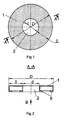
- the device comprises an annular elastic membrane 1 with a central hole 2 which the diameter d of the central hole is above or equal to the width ⁇ of the annular membrane ring.
- the membrane of the aerator includes a sequence of the perforated areas 3 and non-perforated areas 4 alternating along the ring.
- the membrane of the aerator includes at least four perforated areas 3 and four non-perforated areas 4.
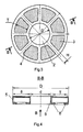
- the membrane of the aerator includes the non-perforated areas 4 being thicker than the perforated areas 3, wherein the non-perforated areas 4 extend outwards from the annular elastic membrane 1 and the non-perforated areas 4 run from the outer side surface 5 up to the inner side surface 6 of the annular elastic membrane 1.
- the inner side of the membrane is made smooth for a tight abutment to corresponding smooth surface in the housing 7 of the aerator.
- the membrane 1 of the aerator is pressed against the housing 7 along the outer and inner side surfaces 5, 6 and is attached to the housing 7 of the aerator by means of the lock joint elements 8.
- the width H of the ring part of the non-perforated areas 4 between adjacent perforated areas 3 may be from 10 to 40 mm.
- the width T of the ring part in the diametral plane of the perforated areas 3 may be from 50 to 150 mm.
- the device operates as follows.
- Availability of at least four perforated areas 3 and four non-perforated areas 4 in the annular membrane 1 of the aerator improves water aeration and mass transfer in the water-air flow 9 above the annular membrane 1. Greater thickness of the non-perforated areas 4 of the annular membrane 1 of aerator in comparison with the perforated areas 3 results in that the membrane 1 the non-perforated areas 4 of greater thickness have lesser elasticity while membrane operating and they are less swelled due to the influence of the compressed air pressure than the perforated areas 3 with lesser thickness.
- the smooth surfaces of the housing 7 and of the membranes 1 function under hydrostatic pressure as a back valve, which prevents access of the water from the aeration tank to the aerator.
- the non-perforated areas 4 run from the outer side surface 5 up to the inner side surface 6 of the annular elastic membrane 1 because the membrane 1 is pressed against the housing 7 along the outer and inner side surfaces 5, 6, what is important for sealing and direct supply of the compressed air to the perforated areas 3 wherefrom this compressed air is dispersed into the water through the perforations with formation of water-air flow 9 therein.
Landscapes
- Chemical & Material Sciences (AREA)
- Chemical Kinetics & Catalysis (AREA)
- Life Sciences & Earth Sciences (AREA)
- Biodiversity & Conservation Biology (AREA)
- Microbiology (AREA)
- Hydrology & Water Resources (AREA)
- Engineering & Computer Science (AREA)
- Environmental & Geological Engineering (AREA)
- Water Supply & Treatment (AREA)
- Organic Chemistry (AREA)
- Aeration Devices For Treatment Of Activated Polluted Sludge (AREA)
Description
- This improvement relates to biological treatment of wastewater, in particular to an apparatus for pneumatic aeration, and may be used in aeration tanks of treatment plants for biological treatment of wastewater and in the fisheries waters intended for the artificial cultivation of fish.
- It is known a device including a membrane of an aerator (see Membrane Disc. SAN-ITAIRE Aeration Systems, http://www.sanitaire.com).
- The known membrane of the aerator operates only by its upper part. A stagnant zone with accumulation of active sludge precipitating onto the bottom is created under the aerator on the bottom of the aeration tank. Just increasing the air flow through the aerator does not help in deleting the stagnant zones under the aerator. Moreover stretching of the perforated dispersing surface of the elastic membrane because of higher pneumatic loading results in increasing the opening degree of the membrane holes and as a consequence, in passing excessive rate of compressed air through the membrane with enlargement of air bubbles above the membrane.
- It is known a membrane of an aerator, for example see patent documents of the Russian Federation
RU 2 220 917 A of 10.01.2004 RU 2 334 686 A of 27.09.2008 RU 2 334 688 A of 27.09.2008 - While operating of the known membrane of the aerator, reduced pressure in the water-air flow above the central opening, into which water enters from the aerator, is created and captures a sludge precipitated in the water-air flow during aeration of wastewater into the water-air flow. Because of reduced pressure in the water flow above the central hole, which is formed via surrounding the central hole by a water-air ring, a narrowing of the water-air flow from the periphery of the annular elastic membrane takes place.
- From the German utility
patent document DE 9 318 676 U1 an aerator of elastic material designed like a hose ring with a gas passage opening is known. - From the European laid open patent application document
EP 0 704 237 A2 a device for gasifying liquids comprising a flat annular membrane is known. - The German patent document
DE 36 32 772 C1 discloses an aerator comprising an annular elastic membrane with a central hole which diameter is above the width of the annular membrane ring. - In the known devices water comes into the water-air flow from the outer and inner side surfaces of the annular membrane only what results in that the annular membrane does not provide sufficient aeration of the water and oxygen mass transfer in the water-air flow above it.
- The object set as the basis of the invention is to provide a membrane of an aerator in which said disadvantages are eliminated and aeration of water and efficiency of oxygen mass transfer are improved by specific design of the membrane.
- The object set is achieved by providing a membrane of an aerator including an annular elastic membrane with a central hole whereby the diameter of the central hole is above or equal to the width of the ring of the annular membrane. According to the invention the annular elastic membrane is characterized in that the membrane of the aerator comprises alternating perforated areas and non-perforated areas along the ring.
- Advantageously improvements of the invented membrane of an aerator are presented in depending claims.
- The membrane of the aerator comprises at least four perforated and four non-perforated areas.
- The membrane of the aerator comprises the non-perforated areas of greater thickness than the perforated areas, the non-perforated areas extending outwards of the annular elastic membrane and the non-perforated areas running from the outer side surface up to the inner side surface of the annular elastic membrane.
- Technical effect is in that providing the diameter of the central hole being above or equal to the width of the annular membrane ring and that the membrane comprises alternating perforated areas and non-perforated areas along the ring, a larger quantity of water has access to the central hole from below and lesser the water-air flow narrowing from the periphery of the annular elastic membrane above the annular elastic membrane takes place.
- Due to alternating of the perforated and non-perforated areas along the ring, water comes into the water-air flow from the annular membrane not only from the outer and inner side surfaces of the annular membrane, but also from the areas between the perforated areas, what improves the aeration of the water and mass transfer in the water-air flow above the annular membrane.
- In case the annular membrane of the aerator includes at least four perforated areas and four non-perforated areas, aeration of water and mass transfer in the water-air flow above the annular membrane are improved.
- In case the membrane of the aerator includes the non-perforated areas of greater thickness than the perforated areas, while using the membrane the said non-perforated areas have lesser elasticity and they are less swelled under the pressure of the compressed air, than the perforated areas with lesser thickness. In this case the influence of hydrostatic water pressure takes place, which is higher by a few millimeters of water column above the non-perforated areas than above the perforated areas of smaller thickness inflated by compressed air pressure, what facilitates the access of water to the water-air flow between the perforated areas along the ring of the membrane.
- The non-perforated areas extend outwards of the annular elastic membrane, since the inner side of the membrane is made smooth for a tight abutment to corresponding smooth surface in the housing of the aerator in case of turning off the compressed air supply into the aerator. In this case being under hydrostatic pressure (it depends on the depth of the aeration tank and immersion depth of the aerator and can reach several meters of water column) the smooth surfaces of the housing and of the membrane function as a back valve, prevents water access from the aeration tank to the aerator.
- The non-perforated areas run from the outer side surface up to the inner side surface of the annular elastic membrane because the membrane is pressed against the housing by its outer and inner side surfaces, what is important for direct feeding of the compressed air to the perforated areas from which this compressed air is dispersed through the perforations into the water with the water-air flow formation therein.
- The improvement is explained by an example and drawings presented below, name-ly:
- Fig. 1,
- which shows a top view of a membrane of the aerator,
- Fig. 2,
- which shows a cross-section along line A-A of the membrane of the aerator according to
Fig. 1 , - Fig. 3,
- which shows a top view of an alternative embodiment of the membrane of the aerator,
- Fig. 4,
- which shows a cross-section along line B-B of the membrane of the aerator according
Fig. 3 , - Fig. 5,
- which shows a view in direction B of the membrane of the aerator according to
Fig. 2 andFig. 4 , - Fig. 6,
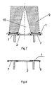
- which shows a schematic side view of the evolvent along the membrane ring midline while operating in water (alternative embodiment),
- Fig. 7,
- which shows a schematic side view of the diametral cross-section of the aerator while operating in water and
- Fig. 8,
- which shows a schematic side view of a diametrical cross-section of the membrane together with the housing in case of non-supplying compressed air to the aerator.
- The list of the reference on the figures:
- 1. Annular elastic membrane.
- 2. Central hole.
- 3. Perforated area
- 4. Non-perforated area
- 5. Outer side surface.
- 6. Inner side surface.
- 7. Housing of the aerator.
- 8. Lock joint elements for joining with the housing of the aerator.
- 9. Water-air flow.
- 10. Water flow above the
central hole 2. - 11. The water flow above the non-perforated area of the
membrane 1. - δ - Width of the annular membrane ring.
- d - Diameter of the central hole.
- D - Diameter of the annular membrane.
- T - Width of the perforated area.
- H - Width of the non-perforated area.
- Specific examples of the aerator membrane embodiments are shown in
Figs. 1 - 8 . The device comprises an annularelastic membrane 1 with acentral hole 2 which the diameter d of the central hole is above or equal to the width δ of the annular membrane ring. The membrane of the aerator includes a sequence of theperforated areas 3 andnon-perforated areas 4 alternating along the ring. The membrane of the aerator includes at least fourperforated areas 3 and fournon-perforated areas 4. The membrane of the aerator includes thenon-perforated areas 4 being thicker than theperforated areas 3, wherein thenon-perforated areas 4 extend outwards from the annularelastic membrane 1 and thenon-perforated areas 4 run from theouter side surface 5 up to the inner side surface 6 of the annularelastic membrane 1. The inner side of the membrane is made smooth for a tight abutment to corresponding smooth surface in thehousing 7 of the aerator. Themembrane 1 of the aerator is pressed against thehousing 7 along the outer and inner side surfaces 5, 6 and is attached to thehousing 7 of the aerator by means of the lockjoint elements 8. - The width H of the ring part of the
non-perforated areas 4 between adjacentperforated areas 3 may be from 10 to 40 mm. The width T of the ring part in the diametral plane of theperforated areas 3 may be from 50 to 150 mm. - The device operates as follows.
- In case the diameter d of the
central hole 2 is above or equal to the width δ of the ring of theannular membrane 1, a large quantity of water has access to thecentral hole 2 from below and lesser narrowing restriction of the water-air flow 9 from the periphery of the annularelastic membrane 1 takes place. Due to sequentially alternating of the perforated 3 and non-perforated 4 areas along the ring, water comes to the water-air flow 9 not only from theannular membrane 1,outer side surfaces 5 and inner side surfaces 6 of theannular membrane 1, but also from the areas between theperforated areas 3, what improves water aeration and mass transfer in the water-air flow 9 above theannular membrane 1. - Availability of at least four
perforated areas 3 and fournon-perforated areas 4 in theannular membrane 1 of the aerator improves water aeration and mass transfer in the water-air flow 9 above theannular membrane 1. Greater thickness of thenon-perforated areas 4 of theannular membrane 1 of aerator in comparison with theperforated areas 3 results in that themembrane 1 thenon-perforated areas 4 of greater thickness have lesser elasticity while membrane operating and they are less swelled due to the influence of the compressed air pressure than theperforated areas 3 with lesser thickness. In this case the influence of hydrostatic pressure of water, which above the non-perforated parts is higher by a few millimeters of water column than above the perforated areas of smaller thickness inflated by air pressure, takes place, what facilitates the access of water into the water-flow between the perforated areas along the ring of themembrane 1. Thenon-perforated areas 4 extend outwards of the annularelastic membrane 1, since the inner side of themembrane 1 is made smooth for a tight abutment to corresponding smooth surface in thehousing 7 of the aerator in case of turning off the compressed air supply into the aerator. In this case the smooth surfaces of thehousing 7 and of themembranes 1 function under hydrostatic pressure as a back valve, which prevents access of the water from the aeration tank to the aerator. Thenon-perforated areas 4 run from theouter side surface 5 up to the inner side surface 6 of the annularelastic membrane 1 because themembrane 1 is pressed against thehousing 7 along the outer and inner side surfaces 5, 6, what is important for sealing and direct supply of the compressed air to theperforated areas 3 wherefrom this compressed air is dispersed into the water through the perforations with formation of water-air flow 9 therein.
Claims (3)
- A membrane of an aerator including an annular elastic membrane (1) with a central hole (2), whereby the diameter (d) of the central hole (2) is above or equal to the width (δ) of the ring of the annular elastic membrane (2) characterized in that it includes sequentially alternating perforated areas (3) and non-perforated areas (4).
- The membrane of the aerator according to claim 1, characterized in that it includes at least four perforated areas (3) and four non-perforated (4) areas.
- The membrane of the aerator according to claim 1, characterized in that it includes the non-perforated areas (3) which are thicker than the perforated areas (3), wherein the non-perforated areas (4) extend outwards of the annular elastic membrane (1) and the non-perforated areas (4) run from the outer side surface (5) up to the inner side surface (6) of the annular elastic membrane (1).
Applications Claiming Priority (1)
| Application Number | Priority Date | Filing Date | Title |
|---|---|---|---|
| RU2010150185/05A RU2451642C9 (en) | 2010-12-07 | 2010-12-07 | Aerator membrane |
Publications (2)
| Publication Number | Publication Date |
|---|---|
| EP2463243A1 EP2463243A1 (en) | 2012-06-13 |
| EP2463243B1 true EP2463243B1 (en) | 2015-12-02 |
Family
ID=45375117
Family Applications (1)
| Application Number | Title | Priority Date | Filing Date |
|---|---|---|---|
| EP11009647.6A Not-in-force EP2463243B1 (en) | 2010-12-07 | 2011-12-07 | A membrane of an aerator |
Country Status (2)
| Country | Link |
|---|---|
| EP (1) | EP2463243B1 (en) |
| RU (1) | RU2451642C9 (en) |
Cited By (1)
| Publication number | Priority date | Publication date | Assignee | Title |
|---|---|---|---|---|
| RU174040U1 (en) * | 2017-01-23 | 2017-09-26 | Научно-производственная фирма с ограниченной ответственностью "Экополимер" | AERATOR |
Families Citing this family (4)
| Publication number | Priority date | Publication date | Assignee | Title |
|---|---|---|---|---|
| DE102009052670B4 (en) * | 2009-11-12 | 2017-10-05 | Sartorius Stedim Biotech Gmbh | Fumigation device for bioreactors |
| RU174135U1 (en) * | 2016-11-08 | 2017-10-03 | Андрей Михайлович Гайсин | UNIVERSAL MEMBRANE FOR AERATORS |
| CN107720951A (en) * | 2017-10-11 | 2018-02-23 | 上海市政工程设计研究总院(集团)有限公司 | A kind of pure oxygen preaerator and its application method |
| RU186723U1 (en) * | 2018-11-06 | 2019-01-30 | Сергей Иванович Петров | UNIVERSAL MEMBRANE FOR SANITARY INSTRUMENTS |
Family Cites Families (11)
| Publication number | Priority date | Publication date | Assignee | Title |
|---|---|---|---|---|
| DE3632772C1 (en) * | 1986-09-26 | 1988-04-28 | Didier Werke Ag | Aerator for introducing gas into a liquid |
| US4981623A (en) * | 1990-03-12 | 1991-01-01 | Aquatec, Inc. | Diffuser for aeration basin |
| US5378355A (en) * | 1992-12-04 | 1995-01-03 | Water Pollution Control Corporation | Direct delivery in-situ diffuser cleaning |
| DE9318676U1 (en) * | 1993-12-07 | 1994-02-24 | Bischof, Franz, Dipl.-Ing., 90489 Nürnberg | Ring tube gasifier for the fine-bubble introduction of gas into a liquid |
| EP0704237B1 (en) * | 1994-09-29 | 1998-09-30 | Karl-Heinz SCHÜSSLER | Device for introducing gas |
| AUPO357396A0 (en) * | 1996-11-12 | 1996-12-05 | Aquatec-Maxcon Pty Ltd | A diffuser for aerating a fluid |
| US6626425B2 (en) * | 2000-02-23 | 2003-09-30 | Ott Gmbh | Gasification device |
| RU2220917C1 (en) * | 2002-05-14 | 2004-01-10 | Общество с ограниченной ответственностью "Научно-производственное предприятие Патфил" | Aeration system |
| US7044453B2 (en) * | 2004-01-08 | 2006-05-16 | Environmental Dynamics, Inc. | Membrane diffuser with uniform gas distribution |
| RU2334686C2 (en) | 2006-09-08 | 2008-09-27 | Общество с ограниченной ответственностью "Экополимер" (ООО "Экополимер") | Aerator |
| RU2334688C2 (en) | 2006-09-08 | 2008-09-27 | Общество с ограниченной ответственностью "Экополимер" (ООО "Экополимер") | Aerator |
-
2010
- 2010-12-07 RU RU2010150185/05A patent/RU2451642C9/en active
-
2011
- 2011-12-07 EP EP11009647.6A patent/EP2463243B1/en not_active Not-in-force
Cited By (1)
| Publication number | Priority date | Publication date | Assignee | Title |
|---|---|---|---|---|
| RU174040U1 (en) * | 2017-01-23 | 2017-09-26 | Научно-производственная фирма с ограниченной ответственностью "Экополимер" | AERATOR |
Also Published As
| Publication number | Publication date |
|---|---|
| RU2451642C1 (en) | 2012-05-27 |
| EP2463243A1 (en) | 2012-06-13 |
| RU2451642C9 (en) | 2012-08-20 |
Similar Documents
| Publication | Publication Date | Title |
|---|---|---|
| EP2463243B1 (en) | A membrane of an aerator | |
| US6367783B1 (en) | Fine bubble diffuser | |
| US5221470A (en) | Apparatus for treating waste water | |
| WO2006130853A3 (en) | Process and apparatus for increasing biological activity in waste treatment in bodies of water | |
| US6016839A (en) | Air diffuser valve | |
| EP2476653B1 (en) | Diffuser tube | |
| PL1996517T3 (en) | An apparatus for disinfection of sea water / ship's ballast water and a method thereof | |
| US8740194B1 (en) | Buoyant aerator array with remote air supply | |
| US5093047A (en) | Gas diffuser | |
| US6511054B1 (en) | Porous air diffuser for treatment of liquids | |
| JP3353225B2 (en) | Aeration device | |
| WO2013146613A1 (en) | Dipping-type membrane separation device | |
| US8678358B1 (en) | Buoyant aerator with support legs | |
| US9809791B1 (en) | Biochemical reactor with a lower divider support structure | |
| KR101060247B1 (en) | Diffuser | |
| KR20190104190A (en) | Aeration element | |
| KR102160967B1 (en) | Stirring Device For Wastewater Treatment | |
| US9909091B1 (en) | Biochemical reactor with an unclogging pipe | |
| JP4582293B2 (en) | Floating body outflow prevention member and water treatment device | |
| KR101943794B1 (en) | An air discharge device of a pollution control device provided with a micro bubble generator | |
| CA3157845A1 (en) | Wastewater aerator/digesters | |
| CN212504218U (en) | Sewage biochemical treatment device | |
| KR101074838B1 (en) | An aeration apparatus | |
| GB2537893A (en) | Submersible diffuser | |
| JP4559108B2 (en) | Gas diffusion device |
Legal Events
| Date | Code | Title | Description |
|---|---|---|---|
| PUAI | Public reference made under article 153(3) epc to a published international application that has entered the european phase |
Free format text: ORIGINAL CODE: 0009012 |
|
| AK | Designated contracting states |
Kind code of ref document: A1 Designated state(s): AL AT BE BG CH CY CZ DE DK EE ES FI FR GB GR HR HU IE IS IT LI LT LU LV MC MK MT NL NO PL PT RO RS SE SI SK SM TR |
|
| AX | Request for extension of the european patent |
Extension state: BA ME |
|
| 17P | Request for examination filed |
Effective date: 20121213 |
|
| GRAP | Despatch of communication of intention to grant a patent |
Free format text: ORIGINAL CODE: EPIDOSNIGR1 |
|
| INTG | Intention to grant announced |
Effective date: 20150710 |
|
| GRAS | Grant fee paid |
Free format text: ORIGINAL CODE: EPIDOSNIGR3 |
|
| GRAA | (expected) grant |
Free format text: ORIGINAL CODE: 0009210 |
|
| RIN1 | Information on inventor provided before grant (corrected) |
Inventor name: MESHENGISSER, YURIY M. Inventor name: KOLESNIK, YURIY V. Inventor name: SMIRNOV, NIKOLAY S. |
|
| AK | Designated contracting states |
Kind code of ref document: B1 Designated state(s): AL AT BE BG CH CY CZ DE DK EE ES FI FR GB GR HR HU IE IS IT LI LT LU LV MC MK MT NL NO PL PT RO RS SE SI SK SM TR |
|
| REG | Reference to a national code |
Ref country code: GB Ref legal event code: FG4D |
|
| REG | Reference to a national code |
Ref country code: AT Ref legal event code: REF Ref document number: 763523 Country of ref document: AT Kind code of ref document: T Effective date: 20151215 Ref country code: CH Ref legal event code: EP |
|
| REG | Reference to a national code |
Ref country code: IE Ref legal event code: FG4D |
|
| REG | Reference to a national code |
Ref country code: DE Ref legal event code: R096 Ref document number: 602011021752 Country of ref document: DE |
|
| REG | Reference to a national code |
Ref country code: NL Ref legal event code: MP Effective date: 20160302 |
|
| REG | Reference to a national code |
Ref country code: LT Ref legal event code: MG4D |
|
| REG | Reference to a national code |
Ref country code: AT Ref legal event code: MK05 Ref document number: 763523 Country of ref document: AT Kind code of ref document: T Effective date: 20151202 |
|
| PG25 | Lapsed in a contracting state [announced via postgrant information from national office to epo] |
Ref country code: ES Free format text: LAPSE BECAUSE OF FAILURE TO SUBMIT A TRANSLATION OF THE DESCRIPTION OR TO PAY THE FEE WITHIN THE PRESCRIBED TIME-LIMIT Effective date: 20151202 Ref country code: LT Free format text: LAPSE BECAUSE OF FAILURE TO SUBMIT A TRANSLATION OF THE DESCRIPTION OR TO PAY THE FEE WITHIN THE PRESCRIBED TIME-LIMIT Effective date: 20151202 Ref country code: NO Free format text: LAPSE BECAUSE OF FAILURE TO SUBMIT A TRANSLATION OF THE DESCRIPTION OR TO PAY THE FEE WITHIN THE PRESCRIBED TIME-LIMIT Effective date: 20160302 |
|
| PG25 | Lapsed in a contracting state [announced via postgrant information from national office to epo] |
Ref country code: FI Free format text: LAPSE BECAUSE OF FAILURE TO SUBMIT A TRANSLATION OF THE DESCRIPTION OR TO PAY THE FEE WITHIN THE PRESCRIBED TIME-LIMIT Effective date: 20151202 Ref country code: GR Free format text: LAPSE BECAUSE OF FAILURE TO SUBMIT A TRANSLATION OF THE DESCRIPTION OR TO PAY THE FEE WITHIN THE PRESCRIBED TIME-LIMIT Effective date: 20160303 Ref country code: RS Free format text: LAPSE BECAUSE OF FAILURE TO SUBMIT A TRANSLATION OF THE DESCRIPTION OR TO PAY THE FEE WITHIN THE PRESCRIBED TIME-LIMIT Effective date: 20151202 Ref country code: AT Free format text: LAPSE BECAUSE OF FAILURE TO SUBMIT A TRANSLATION OF THE DESCRIPTION OR TO PAY THE FEE WITHIN THE PRESCRIBED TIME-LIMIT Effective date: 20151202 Ref country code: PL Free format text: LAPSE BECAUSE OF FAILURE TO SUBMIT A TRANSLATION OF THE DESCRIPTION OR TO PAY THE FEE WITHIN THE PRESCRIBED TIME-LIMIT Effective date: 20151202 Ref country code: NL Free format text: LAPSE BECAUSE OF FAILURE TO SUBMIT A TRANSLATION OF THE DESCRIPTION OR TO PAY THE FEE WITHIN THE PRESCRIBED TIME-LIMIT Effective date: 20151202 Ref country code: BE Free format text: LAPSE BECAUSE OF NON-PAYMENT OF DUE FEES Effective date: 20151231 Ref country code: LV Free format text: LAPSE BECAUSE OF FAILURE TO SUBMIT A TRANSLATION OF THE DESCRIPTION OR TO PAY THE FEE WITHIN THE PRESCRIBED TIME-LIMIT Effective date: 20151202 Ref country code: SE Free format text: LAPSE BECAUSE OF FAILURE TO SUBMIT A TRANSLATION OF THE DESCRIPTION OR TO PAY THE FEE WITHIN THE PRESCRIBED TIME-LIMIT Effective date: 20151202 |
|
| PG25 | Lapsed in a contracting state [announced via postgrant information from national office to epo] |
Ref country code: IS Free format text: LAPSE BECAUSE OF FAILURE TO SUBMIT A TRANSLATION OF THE DESCRIPTION OR TO PAY THE FEE WITHIN THE PRESCRIBED TIME-LIMIT Effective date: 20151202 |
|
| PG25 | Lapsed in a contracting state [announced via postgrant information from national office to epo] |
Ref country code: IT Free format text: LAPSE BECAUSE OF FAILURE TO SUBMIT A TRANSLATION OF THE DESCRIPTION OR TO PAY THE FEE WITHIN THE PRESCRIBED TIME-LIMIT Effective date: 20151202 Ref country code: CZ Free format text: LAPSE BECAUSE OF FAILURE TO SUBMIT A TRANSLATION OF THE DESCRIPTION OR TO PAY THE FEE WITHIN THE PRESCRIBED TIME-LIMIT Effective date: 20151202 |
|
| REG | Reference to a national code |
Ref country code: CH Ref legal event code: PL |
|
| PG25 | Lapsed in a contracting state [announced via postgrant information from national office to epo] |
Ref country code: SK Free format text: LAPSE BECAUSE OF FAILURE TO SUBMIT A TRANSLATION OF THE DESCRIPTION OR TO PAY THE FEE WITHIN THE PRESCRIBED TIME-LIMIT Effective date: 20151202 Ref country code: RO Free format text: LAPSE BECAUSE OF FAILURE TO SUBMIT A TRANSLATION OF THE DESCRIPTION OR TO PAY THE FEE WITHIN THE PRESCRIBED TIME-LIMIT Effective date: 20151202 Ref country code: SM Free format text: LAPSE BECAUSE OF FAILURE TO SUBMIT A TRANSLATION OF THE DESCRIPTION OR TO PAY THE FEE WITHIN THE PRESCRIBED TIME-LIMIT Effective date: 20151202 Ref country code: IS Free format text: LAPSE BECAUSE OF FAILURE TO SUBMIT A TRANSLATION OF THE DESCRIPTION OR TO PAY THE FEE WITHIN THE PRESCRIBED TIME-LIMIT Effective date: 20160402 Ref country code: PT Free format text: LAPSE BECAUSE OF FAILURE TO SUBMIT A TRANSLATION OF THE DESCRIPTION OR TO PAY THE FEE WITHIN THE PRESCRIBED TIME-LIMIT Effective date: 20160404 Ref country code: EE Free format text: LAPSE BECAUSE OF FAILURE TO SUBMIT A TRANSLATION OF THE DESCRIPTION OR TO PAY THE FEE WITHIN THE PRESCRIBED TIME-LIMIT Effective date: 20151202 |
|
| REG | Reference to a national code |
Ref country code: DE Ref legal event code: R097 Ref document number: 602011021752 Country of ref document: DE |
|
| REG | Reference to a national code |
Ref country code: IE Ref legal event code: MM4A |
|
| PG25 | Lapsed in a contracting state [announced via postgrant information from national office to epo] |
Ref country code: MC Free format text: LAPSE BECAUSE OF FAILURE TO SUBMIT A TRANSLATION OF THE DESCRIPTION OR TO PAY THE FEE WITHIN THE PRESCRIBED TIME-LIMIT Effective date: 20151202 |
|
| PLBE | No opposition filed within time limit |
Free format text: ORIGINAL CODE: 0009261 |
|
| STAA | Information on the status of an ep patent application or granted ep patent |
Free format text: STATUS: NO OPPOSITION FILED WITHIN TIME LIMIT |
|
| PG25 | Lapsed in a contracting state [announced via postgrant information from national office to epo] |
Ref country code: IE Free format text: LAPSE BECAUSE OF NON-PAYMENT OF DUE FEES Effective date: 20151207 Ref country code: DK Free format text: LAPSE BECAUSE OF FAILURE TO SUBMIT A TRANSLATION OF THE DESCRIPTION OR TO PAY THE FEE WITHIN THE PRESCRIBED TIME-LIMIT Effective date: 20151202 Ref country code: LI Free format text: LAPSE BECAUSE OF NON-PAYMENT OF DUE FEES Effective date: 20151231 Ref country code: CH Free format text: LAPSE BECAUSE OF NON-PAYMENT OF DUE FEES Effective date: 20151231 |
|
| 26N | No opposition filed |
Effective date: 20160905 |
|
| PG25 | Lapsed in a contracting state [announced via postgrant information from national office to epo] |
Ref country code: SI Free format text: LAPSE BECAUSE OF FAILURE TO SUBMIT A TRANSLATION OF THE DESCRIPTION OR TO PAY THE FEE WITHIN THE PRESCRIBED TIME-LIMIT Effective date: 20151202 |
|
| REG | Reference to a national code |
Ref country code: FR Ref legal event code: ST Effective date: 20161104 |
|
| PG25 | Lapsed in a contracting state [announced via postgrant information from national office to epo] |
Ref country code: BE Free format text: LAPSE BECAUSE OF FAILURE TO SUBMIT A TRANSLATION OF THE DESCRIPTION OR TO PAY THE FEE WITHIN THE PRESCRIBED TIME-LIMIT Effective date: 20151202 |
|
| PG25 | Lapsed in a contracting state [announced via postgrant information from national office to epo] |
Ref country code: FR Free format text: LAPSE BECAUSE OF NON-PAYMENT OF DUE FEES Effective date: 20160202 |
|
| PG25 | Lapsed in a contracting state [announced via postgrant information from national office to epo] |
Ref country code: HU Free format text: LAPSE BECAUSE OF FAILURE TO SUBMIT A TRANSLATION OF THE DESCRIPTION OR TO PAY THE FEE WITHIN THE PRESCRIBED TIME-LIMIT; INVALID AB INITIO Effective date: 20111207 Ref country code: BG Free format text: LAPSE BECAUSE OF FAILURE TO SUBMIT A TRANSLATION OF THE DESCRIPTION OR TO PAY THE FEE WITHIN THE PRESCRIBED TIME-LIMIT Effective date: 20151202 |
|
| PG25 | Lapsed in a contracting state [announced via postgrant information from national office to epo] |
Ref country code: CY Free format text: LAPSE BECAUSE OF FAILURE TO SUBMIT A TRANSLATION OF THE DESCRIPTION OR TO PAY THE FEE WITHIN THE PRESCRIBED TIME-LIMIT Effective date: 20151202 |
|
| PG25 | Lapsed in a contracting state [announced via postgrant information from national office to epo] |
Ref country code: HR Free format text: LAPSE BECAUSE OF FAILURE TO SUBMIT A TRANSLATION OF THE DESCRIPTION OR TO PAY THE FEE WITHIN THE PRESCRIBED TIME-LIMIT Effective date: 20151202 |
|
| PG25 | Lapsed in a contracting state [announced via postgrant information from national office to epo] |
Ref country code: TR Free format text: LAPSE BECAUSE OF FAILURE TO SUBMIT A TRANSLATION OF THE DESCRIPTION OR TO PAY THE FEE WITHIN THE PRESCRIBED TIME-LIMIT Effective date: 20151202 Ref country code: MT Free format text: LAPSE BECAUSE OF FAILURE TO SUBMIT A TRANSLATION OF THE DESCRIPTION OR TO PAY THE FEE WITHIN THE PRESCRIBED TIME-LIMIT Effective date: 20151202 |
|
| PG25 | Lapsed in a contracting state [announced via postgrant information from national office to epo] |
Ref country code: LU Free format text: LAPSE BECAUSE OF NON-PAYMENT OF DUE FEES Effective date: 20151207 |
|
| PG25 | Lapsed in a contracting state [announced via postgrant information from national office to epo] |
Ref country code: MK Free format text: LAPSE BECAUSE OF FAILURE TO SUBMIT A TRANSLATION OF THE DESCRIPTION OR TO PAY THE FEE WITHIN THE PRESCRIBED TIME-LIMIT Effective date: 20151202 |
|
| PG25 | Lapsed in a contracting state [announced via postgrant information from national office to epo] |
Ref country code: AL Free format text: LAPSE BECAUSE OF FAILURE TO SUBMIT A TRANSLATION OF THE DESCRIPTION OR TO PAY THE FEE WITHIN THE PRESCRIBED TIME-LIMIT Effective date: 20151202 |
|
| PGFP | Annual fee paid to national office [announced via postgrant information from national office to epo] |
Ref country code: GB Payment date: 20211201 Year of fee payment: 11 Ref country code: DE Payment date: 20211201 Year of fee payment: 11 |
|
| REG | Reference to a national code |
Ref country code: DE Ref legal event code: R119 Ref document number: 602011021752 Country of ref document: DE |
|
| GBPC | Gb: european patent ceased through non-payment of renewal fee |
Effective date: 20221207 |
|
| PG25 | Lapsed in a contracting state [announced via postgrant information from national office to epo] |
Ref country code: GB Free format text: LAPSE BECAUSE OF NON-PAYMENT OF DUE FEES Effective date: 20221207 Ref country code: DE Free format text: LAPSE BECAUSE OF NON-PAYMENT OF DUE FEES Effective date: 20230701 |