EP2463159A1 - Side airbag device for vehicle - Google Patents
Side airbag device for vehicle Download PDFInfo
- Publication number
- EP2463159A1 EP2463159A1 EP09848040A EP09848040A EP2463159A1 EP 2463159 A1 EP2463159 A1 EP 2463159A1 EP 09848040 A EP09848040 A EP 09848040A EP 09848040 A EP09848040 A EP 09848040A EP 2463159 A1 EP2463159 A1 EP 2463159A1
- Authority
- EP
- European Patent Office
- Prior art keywords
- vehicle
- bag portion
- passenger
- side airbag
- gas
- Prior art date
- Legal status (The legal status is an assumption and is not a legal conclusion. Google has not performed a legal analysis and makes no representation as to the accuracy of the status listed.)
- Granted
Links
Images


Classifications
-
- B—PERFORMING OPERATIONS; TRANSPORTING
- B60—VEHICLES IN GENERAL
- B60R—VEHICLES, VEHICLE FITTINGS, OR VEHICLE PARTS, NOT OTHERWISE PROVIDED FOR
- B60R21/00—Arrangements or fittings on vehicles for protecting or preventing injuries to occupants or pedestrians in case of accidents or other traffic risks
- B60R21/02—Occupant safety arrangements or fittings, e.g. crash pads
- B60R21/16—Inflatable occupant restraints or confinements designed to inflate upon impact or impending impact, e.g. air bags
- B60R21/20—Arrangements for storing inflatable members in their non-use or deflated condition; Arrangement or mounting of air bag modules or components
- B60R21/207—Arrangements for storing inflatable members in their non-use or deflated condition; Arrangement or mounting of air bag modules or components in vehicle seats
-
- B—PERFORMING OPERATIONS; TRANSPORTING
- B60—VEHICLES IN GENERAL
- B60R—VEHICLES, VEHICLE FITTINGS, OR VEHICLE PARTS, NOT OTHERWISE PROVIDED FOR
- B60R21/00—Arrangements or fittings on vehicles for protecting or preventing injuries to occupants or pedestrians in case of accidents or other traffic risks
- B60R21/02—Occupant safety arrangements or fittings, e.g. crash pads
- B60R21/16—Inflatable occupant restraints or confinements designed to inflate upon impact or impending impact, e.g. air bags
- B60R21/23—Inflatable members
- B60R21/231—Inflatable members characterised by their shape, construction or spatial configuration
- B60R21/23138—Inflatable members characterised by their shape, construction or spatial configuration specially adapted for side protection
-
- B—PERFORMING OPERATIONS; TRANSPORTING
- B60—VEHICLES IN GENERAL
- B60R—VEHICLES, VEHICLE FITTINGS, OR VEHICLE PARTS, NOT OTHERWISE PROVIDED FOR
- B60R21/00—Arrangements or fittings on vehicles for protecting or preventing injuries to occupants or pedestrians in case of accidents or other traffic risks
- B60R21/02—Occupant safety arrangements or fittings, e.g. crash pads
- B60R21/16—Inflatable occupant restraints or confinements designed to inflate upon impact or impending impact, e.g. air bags
- B60R21/23—Inflatable members
- B60R21/231—Inflatable members characterised by their shape, construction or spatial configuration
- B60R21/233—Inflatable members characterised by their shape, construction or spatial configuration comprising a plurality of individual compartments; comprising two or more bag-like members, one within the other
-
- B—PERFORMING OPERATIONS; TRANSPORTING
- B60—VEHICLES IN GENERAL
- B60R—VEHICLES, VEHICLE FITTINGS, OR VEHICLE PARTS, NOT OTHERWISE PROVIDED FOR
- B60R21/00—Arrangements or fittings on vehicles for protecting or preventing injuries to occupants or pedestrians in case of accidents or other traffic risks
- B60R21/02—Occupant safety arrangements or fittings, e.g. crash pads
- B60R21/16—Inflatable occupant restraints or confinements designed to inflate upon impact or impending impact, e.g. air bags
- B60R21/23—Inflatable members
- B60R21/231—Inflatable members characterised by their shape, construction or spatial configuration
- B60R21/23138—Inflatable members characterised by their shape, construction or spatial configuration specially adapted for side protection
- B60R2021/23146—Inflatable members characterised by their shape, construction or spatial configuration specially adapted for side protection seat mounted
-
- B—PERFORMING OPERATIONS; TRANSPORTING
- B60—VEHICLES IN GENERAL
- B60R—VEHICLES, VEHICLE FITTINGS, OR VEHICLE PARTS, NOT OTHERWISE PROVIDED FOR
- B60R21/00—Arrangements or fittings on vehicles for protecting or preventing injuries to occupants or pedestrians in case of accidents or other traffic risks
- B60R21/02—Occupant safety arrangements or fittings, e.g. crash pads
- B60R21/16—Inflatable occupant restraints or confinements designed to inflate upon impact or impending impact, e.g. air bags
- B60R21/23—Inflatable members
- B60R21/231—Inflatable members characterised by their shape, construction or spatial configuration
- B60R21/2334—Expansion control features
- B60R21/2346—Soft diffusers
-
- B—PERFORMING OPERATIONS; TRANSPORTING
- B60—VEHICLES IN GENERAL
- B60R—VEHICLES, VEHICLE FITTINGS, OR VEHICLE PARTS, NOT OTHERWISE PROVIDED FOR
- B60R21/00—Arrangements or fittings on vehicles for protecting or preventing injuries to occupants or pedestrians in case of accidents or other traffic risks
- B60R21/02—Occupant safety arrangements or fittings, e.g. crash pads
- B60R21/16—Inflatable occupant restraints or confinements designed to inflate upon impact or impending impact, e.g. air bags
- B60R21/26—Inflatable occupant restraints or confinements designed to inflate upon impact or impending impact, e.g. air bags characterised by the inflation fluid source or means to control inflation fluid flow
- B60R21/261—Inflatable occupant restraints or confinements designed to inflate upon impact or impending impact, e.g. air bags characterised by the inflation fluid source or means to control inflation fluid flow with means other than bag structure to diffuse or guide inflation fluid
Definitions
- the present invention relates to a side airbag device for a vehicle.
- an integral airbag that covers substantially from the head portion to the waist portion of a passenger
- Patent Document 1 Japanese Patent Application Laid-Open No. 10-273010
- Patent Document 2 Japanese Patent Application Laid-Open No. 9-136595
- an object of the present invention is to be able to more appropriately restrain the respective portions of the upper body, including the waist portion, of a passenger by a side airbag at the time of a side collision.
- a first aspect of the present invention is a side airbag device comprising a side airbag comprising an upper bag portion that is positioned at a vehicle upper side, and corresponds to a head portion to a shoulder portion of a passenger seated in a vehicle seat, a lower bag portion that is positioned at a vehicle lower side of the upper bag portion, and corresponds to a waist portion of the passenger, and an intermediate portion that connects a lower edge portion of the upper bag portion and an upper edge portion of the lower bag portion, and corresponds to a chest portion of the passenger, wherein at a time of a side collision, the side airbag receives a supply of gas for inflation and inflates and deploys between the passenger and a vehicle body side portion, and the side airbag device is configured such that a load, that is imparted toward a vehicle transverse direction inner side from the upper bag portion to the shoulder portion when the shoulder portion is restrained by the upper bag portion, decreases at a latter stage of restraint of the shoulder portion.
- the side airbag device for a vehicle relating to the first aspect, at the time of a side collision, the side airbag receives a supply of gas and deploys between the passenger and a vehicle body side portion, and the upper bag portion restrains from the head portion to the shoulder portion, and the lower bag portion restrains the waist portion, and the intermediate portion, that connects the lower edge portion of the upper bag portion and the upper edge portion of the lower bag portion, restrains the chest portion.
- the load that is imparted toward the vehicle transverse direction inner side from the upper bag portion to the shoulder portion of the passenger at this time, decreases at the latter stage of the restraint of the shoulder portion by the upper bag portion, and therefore, the amount of movement of the shoulder portion toward the vehicle transverse direction inner side can be suppressed to an appropriate degree. Therefore, the respective portions of the upper body, including the waist portion, of the passenger can be restrained more appropriately.
- a tubular inflated portion is provided that communicates with a vehicle rear side of the upper bag portion at an end portion at a vehicle upper side, and communicates with a vehicle rear side of the lower bag portion at an end portion at a vehicle lower side, and inflates along a spine direction of the passenger at an initial stage of inflation and deployment of the side airbag.
- the tubular inflated portion inflates along the spine direction of the passenger. Due thereto, the spine of the passenger can be restrained at the initial stage of a side collision, that is earlier than the completion of the inflation and deployment of the side airbag.
- the tubular inflated portion becomes a core region of high pressure at the side airbag at the initial stage of inflation and deployment, the deployment behaviors of the upper bag portion and the lower bag portion thereafter are stable. Therefore, the upper bag portion can be deployed stably at the region corresponding to the head portion to the shoulder portion of the passenger, and the lower bag portion can be deployed stably at the region corresponding to the waist portion of the passenger.
- a tubular inflator at which gas ejection holes are disposed at a vehicle upper side is provided within the tubular inflated portion, and a diffuser, which directs a flow of gas that is ejected from the gas ejection holes toward the upper bag portion side and the lower bag portion side, is provided at the inflator.
- the flow of gas that is ejected from the gas ejection holes of the inflator can be directed to the upper bag portion side and the lower bag portion side by the diffuser that is provided at the inflator. Therefore, the upper bag portion and the lower bag portion can respectively be inflated and deployed appropriately by using a general-purpose inflator that has gas ejection holes at one end thereof.
- an inflated thickness of the upper bag portion when the side airbag inflates and deploys is set to be thicker than an inflated thickness of the lower bag portion
- an internal pressure of the lower bag portion is set to be higher than an internal pressure of the upper bag portion
- the lower bag portion is configured such that inflation and deployment thereof are completed before that of the upper bag portion.
- the inflated thickness of the upper bag portion when the side airbag inflates and deploys is set to be thicker than the inflated thickness of the lower bag portion, the head portion, that is positioned further toward the vehicle transverse direction inner side than the shoulder portion and the waist portion, can be restrained more appropriately by the upper bag portion.
- the waist portion of the passenger can be restrained appropriately by the lower bag portion, even if the inflated thickness of the lower bag portion is thinner than the upper bag portion.
- the waist portion is restrained at an earlier stage than the shoulder portion and the head portion. Due to the waist portion, at which the strength is relatively great among the upper body of the passenger, being restrained at an early stage than the lower bag portion and being moved toward the vehicle transverse direction inner side, the respective portions of the upper body of the passenger, including the waist portion, can be restrained even more appropriately.
- a lower check valve which permits passage of gas toward the lower bag portion side and restricts passage of gas in a direction opposite thereto, is provided at the end portion at the vehicle lower side of the tubular inflated portion.
- the lower bag portion inflates and deploys due to gas that is supplied from the tubular inflated portion through the lower check valve to the lower bag portion.
- the lower check valve restricts this flow of gas, and therefore, the internal pressure of the lower bag portion can be maintained over a longer time. Therefore, the waist portion of the passenger can be restrained appropriately by the lower bag portion.
- an upper check valve which permits passage of gas toward the upper bag portion side and restricts passage of gas in a direction opposite thereto, is provided at the end portion at the vehicle upper side of the tubular inflated portion.
- the upper bag portion inflates and deploys due to gas that is supplied from the tubular inflated portion through the upper check valve to the upper bag portion.
- the upper check valve restricts this flow of gas, and therefore, the internal pressure of the upper bag portion can be maintained over a longer time. Therefore, from the head portion to the shoulder portion of the passenger can be restrained appropriately by the upper bag portion.
- flow path opening surface areas and flow path lengths of the lower check valve and the upper check valve are configured such that gas that is supplied into the tubular inflated portion is distributed in accordance with respective volumes and internal pressure settings of the upper bag portion and the lower bag portion.
- the gas that is supplied into the tubular inflated portion can be distributed in accordance with the respective volumes and internal pressure settings of the upper bag portion and the lower bag portion. Therefore, the upper bag portion and the lower bag portion can respectively be inflated and deployed at desired timings, and, after the gas is supplied, the upper bag portion and the lower bag portion can respectively be maintained at the desired internal pressures.
- an extended bag portion that extends to a region corresponding to a front portion of the chest portion of the passenger, is provided at a vehicle front side lower end edge of the upper bag portion.
- the front portion at which the strength is relatively great among the chest portion of the passenger, can be restrained by the extended bag portion that is provided at a vehicle front side lower end edge of the upper bag portion. Therefore, the load, that is inputted to the passenger when the passenger is restrained by the side airbag, can be dispersed.
- the side airbag device for a vehicle relating to the first aspect of the present invention, there is the excellent effect that, at the time of a side collision, the respective portions of the upper body, including the waist portion, of a passenger can be restrained more appropriately by the side airbag.
- the upper bag portion and the lower bag portion can respectively be inflated and deployed appropriately by using a general-purpose inflator that has gas ejection holes at one end thereof.
- the upper bag portion and the lower bag portion can respectively be inflated and deployed at desired timings, and, after the gas is supplied, the upper bag portion and the lower bag portion can respectively be maintained at the desired internal pressures.
- a side airbag device 10 for a vehicle relates to, for example, a side airbag device that is installed in the side portion of a seat back 14 at a vehicle seat 12, and has a side airbag 24 having an upper bag portion 16, a lower bag portion 18 and an intermediate portion 22.
- the side airbag 24 is configured so as to, at the time of a side collision, receive a supply of gas for inflation from an inflator 26 for example, and inflate and deploy between a passenger 28 and a side door 30 that is an example of a vehicle body side portion.
- the upper bag portion 16, the lower bag portion 18, the intermediate portion 22, and a tubular inflated portion 38 that is described later are configured integrally due to, for example, a passenger side base cloth 32 and a door side base cloth 34 being sewn.
- the passenger side base cloth 32 and the door side base cloth 34 are configured by using, for example, non-extendable materials.
- the side airbag 24 is not limited to being manufactured by sewing, and may be made by bag-weaving.
- the upper bag portion 16 is positioned at the vehicle upper side, and corresponds to a head portion 28H to a shoulder portion 28S of the passenger 28 seated in the vehicle seat 12, and is an inflating portion that inflates toward the vehicle transverse direction outer side (the side door 30 side) of a region from the head portion 28H to the shoulder portion 28.
- a vent hole 36 for example is provided in the upper bag portion 16.
- vent hole 36 it is desirable to provide the vent hole 36 at a position that does not overlap the passenger 28 or the side door 30 in the vehicle transverse direction (at a position that is further upward than a door trim 31), in order for the vent hole 36 to not be blocked at the time of restraint of the passenger 28.
- the vent hole 36 In order to make the load, that is inputted from the upper bag portion 16 to the shoulder portion 28S toward the vehicle transverse direction inner side, decrease at the latter stage of restraint of the shoulder portion 28S, it is desirable that the vent hole 36 be formed at a position, of the upper bag portion 16, at which the time of the arrival of gas from the inflator 26 is late.
- the vent hole 36 is formed, for example, at one place at the lower end portion of the vehicle front side, of the vehicle transverse direction inner side portion of the upper bag portion 16.
- vent hole 36 the position, shape and number of the vent hole 36 are not limited to the illustrated example. Further, as a structure that is equivalent to the vent hole 36, a non-sewn portion (not illustrated) may be provided at a portion of the sewn portion of the passenger side base cloth 32 and the door side base cloth 34 at the upper bag portion 16, or a planned opening portion (not illustrated), that opens when the internal pressure of the upper bag portion 16 becomes greater than or equal to a predetermined value, may be provided.
- the lower bag portion 18 is positioned at the vehicle lower side of the upper bag portion 16, and corresponds to a waist portion 28W of the passenger 28, and is an inflated portion that inflates at the vehicle transverse direction outer side (the side door 30 side) of the waist portion 28W.
- the inflated shape of the lower bag portion 18 in a vehicle side view is set so as to be able to restrain at least the central position (not illustrated) of the pelvis. This is because the volume of the side airbag 24 is reduced, an inflator that is compact and has a small output can be used as the inflator 26, and the increase in cost can be suppressed.
- an inflated thickness TU of the upper bag portion 16 when the side airbag 24 is inflated and deployed is set to be thicker than an inflated thickness TL of the lower bag portion 18.
- the internal pressure of the lower bag portion 18 when the side airbag 24 is inflated and deployed is set to be higher than the internal pressure of the upper bag portion 16.
- the lower bag portion 18 is set to have, for example, a smaller volume than the upper bag portion 16 such that inflation and deployment thereof is completed before that of the upper bag portion 16 when the side airbag 24 inflates and deploys.
- the intermediate portion 22 connects a lower edge portion 16L of the upper bag portion 16 and an upper edge portion 18U of the lower bag portion 18, and is a region corresponding to a chest portion 28C of the passenger 28, and is configured as a film-shaped non-inflating portion by, for example, the passenger side base cloth 32 and the door side base cloth 34 being superposed.
- this intermediate portion 22 is set so as to, for example, deploy at the region from the central portion of the chest portion 28C to the back side of the passenger 28, as seen in a vehicle side view.
- this intermediate portion 22 is not limited to a non-inflating portion, and may be a thin inflated portion whose inflated thickness in the vehicle transverse direction is smaller than the upper bag portion 16 and the lower bag portion 18:
- the tubular inflated portion 38 that communicates with the vehicle rear side of the upper bag portion 16 at an end portion 42 at the vehicle upper side, and communicates with the vehicle rear side of the lower bag portion 18 at an end portion 44 at the vehicle lower side, and inflates along the spine direction of the passenger 28 at the initial stage of inflation and deployment of the side airbag 24, is provided at the side airbag 24.
- the end portion 42 at the vehicle upper side of the tubular inflated portion 38 is positioned, for example, at a height in a vicinity of the shoulder portion 28S of the passenger 28, and the end portion 44 at the vehicle lower side is positioned, for example, at a height in a vicinity of an abdomen portion 28A of the passenger 28.
- a reinforcing cloth 40 that is tubular for example, is sewn to the inner surface of the tubular inflated portion 38.
- this reinforcing cloth 40 is the end portion 42 at the vehicle upper side of the tubular inflated portion 38 that communicates with the vehicle rear side of the upper bag portion 16
- the lower end of the reinforcing cloth 40 is the end portion 44 at the vehicle lower side of the tubular reinforcing portion 38 that communicates with the vehicle rear side of the lower bag portion 18.
- the inflator 26 is fixed to an unillustrated seat back frame, and is connected to an airbag ECU via a wire harness, and is configured so as to operate by operation current from the airbag ECU and supply gas for inflation to the side airbag 24.
- the airbag ECU is configured so as to cause operation current to flow to the inflator 26 when the airbag ECU judges a side collision due to a signal from a collision sensor (not illustrated).
- the present embodiment is configured as described above, and operation thereof is described hereinafter.
- side collision load F Fig. 3 , Fig. 4
- operation current is made to flow from the airbag ECU to the inflator 26.
- the inflator 26 receives the operation current and operates, and a causes a large amount of gas to be ejected from the gas ejection holes 26A.
- the side airbag 24 Due to this gas being supplied into the side airbag 24, the side airbag 24 swells-out from the seat back 14, and inflates and deploys between the passenger 28 and the side door 30.
- the upper bag portion 16 enters into the gap between, for example, a glass 33 of the side door 30 and the passenger 28, and inflates and deploys
- the lower bag portion 18 enters into the gap between, for example, the door trim 31 of the side door 30 and the passenger 28, and inflates and deploys.
- the head portion 28H to the shoulder portion 28S is restrained by the upper bag portion 16 and the waist portion 28W is restrained by the lower bag portion 18, and further, the chest portion 28C and the abdomen portion 28A can be restrained by the intermediate portion 22 that connects the lower edge portion of the upper bag portion 16 and the upper edge portion of the lower bag portion 18.
- the inflator 26 is provided within the tubular inflated portion 38. that is reinforced by the reinforcing cloth 40, the gas that is ejected from the gas ejection holes 26A is first supplied into the tubular inflated portion 38. Due thereto, at the initial stage of inflation and deployment of the side airbag 24, the tubular inflated portion 38 inflates along the spine direction of the passenger 28. Due to this tubular inflated portion 38, the spine of the passenger 28 can be restrained at the initial stage of the side collision that is earlier than the completion of the inflation and deployment of the side airbag 24.
- the tubular inflated portion 38 becomes a core region of high pressure at the side airbag 24 at the initial stage of inflation and deployment, the deployment behaviors of the upper bag portion 16 and the lower bag portion 18 thereafter are stable. Due thereto, the upper bag portion 16 receives a supply of gas from the end portion 42 at the vehicle upper side of the tubular inflated portion 38, and the upper bag portion 16 deploys stably at the region corresponding to the head portion 28H to the shoulder portion 28S of the passenger 28. Further, the lower bag portion 18 receives a supply of gas from the end portion 44 at the vehicle lower side of the tubular inflated portion 38, and deploys stably at the region corresponding to the waist portion 28W of the passenger 28.
- the inflated thickness TU of the upper bag portion 16 when the side airbag 24 is inflated and deployed is set to be thicker than the inflated thickness TL of the lower bag portion 18. Therefore, the head portion 28H, that is positioned further toward the vehicle transverse direction inner side than the shoulder portion 28S and the waist portion 28W, can be restrained appropriately by the upper bag portion 16.
- the load to the chest portion 28C can be reduced.
- the upper bag portion 16 is pressed from vehicle transverse direction both sides by the passenger 28 and the side door 30, and therefore, gas within the upper bag portion 16 is discharged-out through the vent hole 36 ( Fig. 2 ).
- the load that is imparted toward the vehicle transverse direction inner side from the upper bag portion 16 to the shoulder portion 28S of the passenger 28, decreases at the latter stage of restraint of the shoulder portion 28S by the upper bag portion 16, and therefore, the amount of movement of the shoulder portion 28S toward the vehicle transverse direction inner side can be suppressed to an appropriate degree.
- the vent hole 36 is provided, for example, at one place at the lower end portion of the vehicle front side of the vehicle transverse direction inner side portion of the upper bag portion 16, the flowing-out of gas in the inflating and deploying process of the upper bag portion 16 is suppressed. Due thereto, the initial internal pressure of the upper bag portion 16 can be increased sufficiently.
- the internal pressure of the lower bag portion 18 is set to be higher than the internal pressure of the upper bag portion 16, even if the inflated thickness of the lower bag portion 18 is thinner than the upper bag portion 16, the waist portion 28W of the passenger 28 can be restrained appropriately by the lower bag portion 18.
- the volume of the lower bag portion 18 is set to an extent such that at least the central position (not illustrated) of the pelvis in a vehicle side view can be restrained, and inflation and deployment are completed before the upper bag portion 16. Therefore, the waist portion 28W of the passenger 28 is restrained at an earlier stage than the shoulder portion 28S and the head portion 28H. Due to the waist portion 28W, at which the strength is relatively great among the upper body of the passenger 28, being restrained at an early stage than the lower bag portion 18 and being moved toward the vehicle transverse direction inner side, the respective portions of the upper body of the passenger 28, including the waist portion 28W, can be restrained even more appropriately by the side airbag 24.
- a central line CL of the upper body as seen from the front of the passenger 28 is maintained substantially rectilinearly even while tilting with respect to the vehicle vertical direction, and therefore, the posture of the passenger 28 does not vary greatly.
- the intermediate portion 22 is a non-inflating portion that is film-shaped and whose thickness is thinner than the upper bag portion 16 and the lower bag portion 18. Therefore, the load that is inputted from the intermediate portion 22 to the chest portion 28C can be decreased due to the chest portion 28C of the passenger 28 being restrained by the intermediate portion 22 after the shoulder portion 28S is pushed by the upper bag portion 16 earlier.
- the posture of the passenger 28 at the time of a side collision can be controlled appropriately by the side airbag 24 that is integral.
- the tubular inflated portion 38 can also be made to be the structure of modified example 1 shown in Fig. 5 .
- a lower check valve 46 which permits passage of gas to the lower bag portion 18 side and restricts passage of gas in the direction opposite thereto, is provided at the end portion 44 at the vehicle lower side of the tubular inflated portion 38
- an upper check valve 48 which permits passage of gas to the upper bag portion 16 side and restricts passage of gas in the direction opposite thereto, is provided at the end portion 42 at the vehicle upper side of the tubular inflated portion 38.
- the lower check valve 46 and the upper check valve 48 are configured by, for example, base cloths that are flexible being sewn in the shapes of funnels that taper respectively toward opening portion 46A, 48A sides, and are sewn to the inner peripheral surface of the tubular inflated portion 38 at base end portions 46B, 48B for example.
- the flow path opening surface areas and flow path lengths of this lower check valve 46 and upper check valve 48 are configured such that the gas that is supplied from the inflator 26 into the tubular inflated portion 38 is distributed in accordance with the respective volumes and internal pressure settings of the upper bag portion 16 and the lower bag portion 18.
- the flow path opening surface area of the opening portion 46A is set to be relatively small in accordance with the volume of the lower bag portion 18. Due thereto, flowing-in of gas from the tubular inflated portion 38 into the lower bag portion 18 that has a relatively small volume is suppressed, the inflation timing of the lower bag portion 18 is delayed, and flowing-in of gas into the upper bag portion 16 can be promoted.
- a flow path length 46L of the lower check valve 46 is set to be relatively small in consideration of the timing of restraining the waist portion 28W of the passenger 28 by the lower bag portion 18.
- the flow path length 46L is small, it is difficult for the base cloth of the lower check valve 46 to bend. Accordingly, when the supply of gas to the lower bag portion 18 ends and gas attempts to flow backward from the lower bag portion 18 to the tubular inflated portion 38 side, and concretely, when the internal pressure of the lower bag portion 18 becomes higher than the internal pressure of the tubular inflated portion 38 due to the restraint of the waist portion 28W of the passenger 28, the opening portion 46A of the lower check valve 46 closes relatively slowly as shown in Fig. 6 .
- the internal pressure of the lower bag portion 18 can be maintained over a longer time while the supplying of gas to the upper bag portion 16 is promoted, by restricting the backward flow of gas while delaying the closing timing of the lower check valve 46 in this way. Further, the waist portion 28W (see Fig. 1 , Fig. 4 ) of the passenger 28 can be restrained appropriately by this lower bag portion 18.
- the flow path opening surface area of the opening portion 48A is set to be relatively large in accordance with the volume of the upper bag portion 16. Due thereto, flowing-in of gas from the tubular inflated portion 38 to the upper bag portion 16 that has a relatively large volume is promoted, and the inflation timing of the upper bag portion 16 can be advanced, and flowing-in of gas to the lower bag portion 18 that has a relatively small volume can be suppressed.
- a flow path length 48L of the upper check valve 48 is set to be relatively large in consideration of the timing of restraint of the shoulder portion 28S and the head portion 28H of the passenger 28 by the upper bag portion 16.
- the flow path length 48L is large, it is easy for the base cloth of the upper check valve 48 to bend. Accordingly, when the supply of gas to the upper bag portion 16 ends and gas attempts to flow backward from the upper bag portion 16 to the tubular inflated portion 38 side, and concretely, when the internal pressure of the upper bag portion 16 becomes higher than the internal pressure of the tubular inflated portion 38 due to the restraint of the shoulder portion 28S and the head portion 28H of the passenger 28, the opening portion 48A of the upper check valve 48 closes relatively quickly as shown in Fig. 7 .
- the internal pressure of the upper bag portion 16 can be maintained over a longer time, by restricting the backward flow of gas while advancing the closing timing of the upper check valve 48 in this way. Further, the shoulder portion 28S and the head portion 28H (see Fig. 1 , Fig. 4 ) of the passenger 28 can be restrained appropriately by this upper bag portion 16.
- the gas that is supplied into the tubular inflated portion 38 can be distributed in accordance with the respective volumes and internal pressure settings of the upper bag portion 16 and the lower bag portion 18. Therefore, the upper bag portion 16 and the lower bag portion 18 can respectively be inflated and deployed at desired timings, and, after the gas is supplied, the upper bag portion 16 and the lower bag portion 18 can respectively be maintained at the desired internal pressures.
- the tubular inflated portion 38 can also be made to be the structure of modified example 2 shown in Fig. 8 .
- a tether 50 that restricts the inflated thickness of the upper bag portion 16, is provided within the upper bag portion 16.
- This tether 50 is sewn respectively to the passenger side base cloth 32 and the door side base cloth 34 at end edges 50A at the vehicle transverse both sides, and extends, for example, along the longitudinal direction of the tubular inflated portion 38.
- the front-rear position of the tether 50 is arbitrary, it is preferably a front-rear position that corresponds to the shoulder portion 28S or the head portion 28H of the passenger 28 as shown in Fig. 9 .
- a predetermined gap 52 is provided between an upper end 50U of the tether 50 and an upper edge portion 16U of the upper bag portion 16, and a predetermined gap 54 is provided also between a lower end 50L of the tether 50 and the lower edge portion 16L of the upper bag portion 16.
- the upper bag portion 16 interior is divided by this tether 50 into a region 56 at the vehicle front side and a region 58 at the vehicle rear side, and the region 58 at the vehicle rear side also serves as the upper portion of the tubular inflated portion 38. Accordingly, when the side airbag 24 inflates and deploys, the tubular inflated portion 38 inflates to an even higher position, along the spine direction of the passenger 28 (see Fig. 1 ).
- the region 56 at the vehicle front side of the tether 50 inflates and deploys due to gas, that is within the region 58 at the vehicle rear side, flowing-in through the gaps 52, 54 that are above and below the tether 50.
- the inflated thickness of the upper bag portion 16 that is inflated and deployed is restricted by the tether 50.
- valley portions 60 that run along the longitudinal directions of the end edges 50A of the tether 50, are formed at the vehicle transverse direction both sides of the upper bag portion 16.
- the passenger 28 can be restrained more stably due to the shoulder portion 28S or the head portion 28H entering-into the valley portion 60.
- the intermediate portion 22 can also be made to be the structure of modified example 3 shown in Fig. 10 .
- the front edge of the intermediate portion 22 is formed so as to connect the front end of the lower edge portion 16L of the upper bag portion 16 and the front end of the upper edge portion 18U of the lower bag portion 18.
- the region of the intermediate portion 22 is deployed toward the vehicle front side to a region that corresponds to a front portion 28F of the chest portion 28C of the passenger 28.
- the front portion 28F at which the strength is relatively great among the chest portion 28C of the passenger 28, can be stably restrained by the intermediate portion 22. Further, the abdomen portion 28A of the passenger 28 also can be restrained by the intermediate portion 22.
- the intermediate portion 22 can also be made to be the structure of modified example 4 shown in Fig. 11 .
- an extended bag portion 16E that extends to the region corresponding to the front portion 28F of the chest portion 28C of the passenger 28, is provided at the vehicle front side lower end edge of the upper bag portion 16. Further, the intermediate portion 22 also is deployed toward the vehicle front side, in the same way as modified example 3.
- the front portion 28F at which the strength is relatively great among the chest portion 28C of the passenger 28, can be restrained by this extended bag portion 16E. Therefore, the load, that is inputted to the passenger 28 when the passenger 28 is restrained by the side airbag 24, can be dispersed. Further, due thereto, input of load to a region, at which the strength is relatively small, of the passenger 28 can be suppressed.
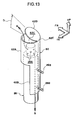
- a diffuser 62 which directs the flow of gas that is ejected from the gas ejection holes 26A toward the upper bag portion 16 side and the lower bag portion 18 side, may be provided at the inflator 26.
- This diffuser 62 is, together with the inflator 26 for example, fixed to a seat back frame 64 that is the skeleton of the seat back 14.
- two stud bolts 26B are provided at the inflator 26 so as to stand in a direction orthogonal to the axial direction of the inflator 26. These stud bolts 26B pass-through a lower portion 62B of the diffuser 62 and project-out. Due to the stud bolts 26B being passed-through the seat back frame 64 and being fastened by nuts (not illustrated), the inflator 26 and the diffuser 62 are fastened and fixed to the seat back frame 64.
- the diffuser 62 is configured to have an upper portion 62A that is cylindrical-tube-shaped and that has a larger diameter than the inflator 26, the lower portion 62B that is connected with the lower side of the rear portion of the upper portion 62A, and a top wall portion 62D that is joined to the rear portion of the top end of the upper portion 62A.
- gas is ejected in a radial form in the radial direction of the inflator 26 from the gas ejection holes 26A.
- this gas due to this gas being received at the upper portion 62A that is cylindrical-tube-shaped, the flow of gas can be restricted to the axial direction of the inflator 26. This gas flows in an arrow A direction toward the upper bag portion 16 ( Fig. 12 ), and flows in an arrow B direction toward the lower bag portion 18 ( Fig. 12 ).
- the lower portion 62B of the diffuser 62 is configured with a portion of a cylindrical tube, that has the same curvature as the upper portion 62A for example, being a curved portion that extends toward the axial direction lower side of the inflator 26, and, in addition to performing as a fixing portion to the seat back frame 64 ( Fig. 12 ), also performs as a guide plate that guides gas in the arrow B direction.
- the top wall portion 62D is configured so as to open slightly toward the vehicle upper side due to a joined portion 62E with the upper portion 62A deforming due to the pressure of the gas that is ejected from the gas ejection holes 26A of the inflator 26. Due to the top wall portion 62D opening, an opening portion 62C is formed at the upper end of the upper portion 62A, and gas flows in the arrow A direction from the opening portion 62C toward the upper bag portion 16 side (see Fig. 12 ).
- the flowing direction of the gas can be controlled by an opening angle D of the top wall portion 62D at this time. If the opening angle D of the top wall portion 62D is set to be large, the flow of gas can be directed toward the vehicle upper side. Further, if the opening angle D of the top wall portion 62D is set to be small, the flow of gas can be directed toward the vehicle front side. Accordingly, the way that the upper bag portion 16 inflates and deploys, that is what region of the upper bag portion 16 is to be inflated preferentially, can also be controlled by the settings of the diffuser 62.
- the structure of the diffuser 62 is not limited to this, and for example, may be a structure in which the top wall portion 62D is not provided as shown in Fig. 14 .
- the flow of the gas that is ejected from the gas ejection holes 26A of the inflator 26 can be directed toward the upper bag portion 16 side and the lower bag portion 18 side by the diffuser 62 that is provided at the inflator 26. Therefore, the upper bag portion 16 and the lower bag portion 18 can respectively be inflated and deployed appropriately by using the general-purpose inflator 26 that has the gas ejection holes 26A at one end thereof.
- the side airbag device 10 for a vehicle is provided at the side portion of the seat back 14, the side airbag device 10 for a vehicle is not limited to this, and may be provided at the inner side of the door trim 31 at the side door 30.
- the side door 30 is presented as the vehicle body side portion, the vehicle body side portion is not limited to this, may be a region of the vehicle body that is positioned at the side of the passenger, and also includes a non-door portion.
Landscapes
- Engineering & Computer Science (AREA)
- Mechanical Engineering (AREA)
- Air Bags (AREA)
Abstract
Description
- The present invention relates to a side airbag device for a vehicle.
- There is disclosed, in an integral airbag that covers substantially from the head portion to the waist portion of a passenger, a structure in which the integral airbag is divided at least in three in the height direction into an airbag portion that protects substantially the head portion, and airbag portion that protects substantially from the shoulder portion to the chest portion, and an airbag portion that protects substantially from the chest portion to the waist portion, and that causes the airbag portion that protects substantially the head portion and the airbag portion that protects substantially from the chest portion to the waist portion to inflate substantially simultaneously, and next causes the airbag portion that protects substantially from the shoulder portion to the chest portion to inflate (see Patent Document 1).
- Further, there is disclosed a structure in which a bag for the chest portion deploys from the side portion of a seat back, at the inner surface side of a door trim or the like that corresponds to the passenger chest portion, and successively, a bag for the head portion deploys at the inner surface side of a window glass that corresponds to the passenger chest portion, and the bag for the chest portion and the seat back are connected to the bag for the head portion in advance via a connecting sheet, and the bag for the head portion after deployment is held so as to be unable to move toward the vehicle outer side (see Patent Document 2).
- [Patent Document 1] Japanese Patent Application Laid-Open No.
10-273010 9-136595 - However, when taking into consideration the behavior of the passenger at the time of a side collision, there is still room for improvement with regard to restraining the passenger by the side airbag.
- In view of the above-described circumstances, an object of the present invention is to be able to more appropriately restrain the respective portions of the upper body, including the waist portion, of a passenger by a side airbag at the time of a side collision.
- A first aspect of the present invention is a side airbag device comprising a side airbag comprising an upper bag portion that is positioned at a vehicle upper side, and corresponds to a head portion to a shoulder portion of a passenger seated in a vehicle seat, a lower bag portion that is positioned at a vehicle lower side of the upper bag portion, and corresponds to a waist portion of the passenger, and an intermediate portion that connects a lower edge portion of the upper bag portion and an upper edge portion of the lower bag portion, and corresponds to a chest portion of the passenger, wherein at a time of a side collision, the side airbag receives a supply of gas for inflation and inflates and deploys between the passenger and a vehicle body side portion, and the side airbag device is configured such that a load, that is imparted toward a vehicle transverse direction inner side from the upper bag portion to the shoulder portion when the shoulder portion is restrained by the upper bag portion, decreases at a latter stage of restraint of the shoulder portion.
- In the side airbag device for a vehicle relating to the first aspect, at the time of a side collision, the side airbag receives a supply of gas and deploys between the passenger and a vehicle body side portion, and the upper bag portion restrains from the head portion to the shoulder portion, and the lower bag portion restrains the waist portion, and the intermediate portion, that connects the lower edge portion of the upper bag portion and the upper edge portion of the lower bag portion, restrains the chest portion. The load, that is imparted toward the vehicle transverse direction inner side from the upper bag portion to the shoulder portion of the passenger at this time, decreases at the latter stage of the restraint of the shoulder portion by the upper bag portion, and therefore, the amount of movement of the shoulder portion toward the vehicle transverse direction inner side can be suppressed to an appropriate degree. Therefore, the respective portions of the upper body, including the waist portion, of the passenger can be restrained more appropriately.
- In a second aspect of the present invention, in the side airbag device for a vehicle relating to the first aspect, a tubular inflated portion is provided that communicates with a vehicle rear side of the upper bag portion at an end portion at a vehicle upper side, and communicates with a vehicle rear side of the lower bag portion at an end portion at a vehicle lower side, and inflates along a spine direction of the passenger at an initial stage of inflation and deployment of the side airbag.
- In the side airbag device for a vehicle relating to the second aspect, at the initial stage of inflation and deployment of the side airbag, the tubular inflated portion inflates along the spine direction of the passenger. Due thereto, the spine of the passenger can be restrained at the initial stage of a side collision, that is earlier than the completion of the inflation and deployment of the side airbag.
- Further, because the tubular inflated portion becomes a core region of high pressure at the side airbag at the initial stage of inflation and deployment, the deployment behaviors of the upper bag portion and the lower bag portion thereafter are stable. Therefore, the upper bag portion can be deployed stably at the region corresponding to the head portion to the shoulder portion of the passenger, and the lower bag portion can be deployed stably at the region corresponding to the waist portion of the passenger.
- In a third aspect of the present invention, in the side airbag device for a vehicle relating to the second aspect, a tubular inflator at which gas ejection holes are disposed at a vehicle upper side, is provided within the tubular inflated portion, and a diffuser, which directs a flow of gas that is ejected from the gas ejection holes toward the upper bag portion side and the lower bag portion side, is provided at the inflator.
- In the side airbag device for a vehicle relating to the third aspect, the flow of gas that is ejected from the gas ejection holes of the inflator, can be directed to the upper bag portion side and the lower bag portion side by the diffuser that is provided at the inflator. Therefore, the upper bag portion and the lower bag portion can respectively be inflated and deployed appropriately by using a general-purpose inflator that has gas ejection holes at one end thereof.
- In a fourth aspect of the present invention, in the side airbag device for a vehicle relating to the second aspect or the third aspect, an inflated thickness of the upper bag portion when the side airbag inflates and deploys is set to be thicker than an inflated thickness of the lower bag portion, an internal pressure of the lower bag portion is set to be higher than an internal pressure of the upper bag portion, and the lower bag portion is configured such that inflation and deployment thereof are completed before that of the upper bag portion.
- In the side airbag device for a vehicle relating to the fourth aspect, because the inflated thickness of the upper bag portion when the side airbag inflates and deploys is set to be thicker than the inflated thickness of the lower bag portion, the head portion, that is positioned further toward the vehicle transverse direction inner side than the shoulder portion and the waist portion, can be restrained more appropriately by the upper bag portion.
- Further, because the internal pressure of the lower bag portion is set to be higher than the internal pressure of the upper bag portion, the waist portion of the passenger can be restrained appropriately by the lower bag portion, even if the inflated thickness of the lower bag portion is thinner than the upper bag portion.
- Moreover, because inflation and deployment of the lower bag portion are completed before the upper bag portion, the waist portion is restrained at an earlier stage than the shoulder portion and the head portion. Due to the waist portion, at which the strength is relatively great among the upper body of the passenger, being restrained at an early stage than the lower bag portion and being moved toward the vehicle transverse direction inner side, the respective portions of the upper body of the passenger, including the waist portion, can be restrained even more appropriately.
- In a fifth aspect of the present invention, in the side airbag device for a vehicle relating to the fourth aspect, a lower check valve, which permits passage of gas toward the lower bag portion side and restricts passage of gas in a direction opposite thereto, is provided at the end portion at the vehicle lower side of the tubular inflated portion.
- In the side airbag device for a vehicle relating to the fifth aspect, at the time of a side collision, the lower bag portion inflates and deploys due to gas that is supplied from the tubular inflated portion through the lower check valve to the lower bag portion. When the supply of gas ends and gas attempts to flow backward from the lower bag portion to the tubular inflated portion side, the lower check valve restricts this flow of gas, and therefore, the internal pressure of the lower bag portion can be maintained over a longer time. Therefore, the waist portion of the passenger can be restrained appropriately by the lower bag portion.
- In a sixth aspect of the present invention, in the side airbag device for a vehicle relating to the fifth aspect, an upper check valve, which permits passage of gas toward the upper bag portion side and restricts passage of gas in a direction opposite thereto, is provided at the end portion at the vehicle upper side of the tubular inflated portion.
- In the side airbag device for a vehicle relating to the sixth aspect, at the time of a side collision, the upper bag portion inflates and deploys due to gas that is supplied from the tubular inflated portion through the upper check valve to the upper bag portion. When the supply of gas ends and gas attempts to flow backward from the upper bag portion to the tubular inflated portion side, the upper check valve restricts this flow of gas, and therefore, the internal pressure of the upper bag portion can be maintained over a longer time. Therefore, from the head portion to the shoulder portion of the passenger can be restrained appropriately by the upper bag portion.
- In a seventh aspect of the present invention, in the side airbag device for a vehicle relating to the sixth aspect, flow path opening surface areas and flow path lengths of the lower check valve and the upper check valve are configured such that gas that is supplied into the tubular inflated portion is distributed in accordance with respective volumes and internal pressure settings of the upper bag portion and the lower bag portion.
- In the side airbag device for a vehicle relating to the seventh aspect, by setting the flow path opening surface areas and the flow path lengths at the lower check valve and the upper check valve, the gas that is supplied into the tubular inflated portion can be distributed in accordance with the respective volumes and internal pressure settings of the upper bag portion and the lower bag portion. Therefore, the upper bag portion and the lower bag portion can respectively be inflated and deployed at desired timings, and, after the gas is supplied, the upper bag portion and the lower bag portion can respectively be maintained at the desired internal pressures.
- In an eighth aspect of the present invention, in the side airbag device for a vehicle relating to any one aspect of the first through seventh aspects, an extended bag portion, that extends to a region corresponding to a front portion of the chest portion of the passenger, is provided at a vehicle front side lower end edge of the upper bag portion.
- In the side airbag device for a vehicle relating to the eighth aspect, at the time of a side collision, the front portion, at which the strength is relatively great among the chest portion of the passenger, can be restrained by the extended bag portion that is provided at a vehicle front side lower end edge of the upper bag portion. Therefore, the load, that is inputted to the passenger when the passenger is restrained by the side airbag, can be dispersed.
- As described above, in accordance with the side airbag device for a vehicle relating to the first aspect of the present invention, there is the excellent effect that, at the time of a side collision, the respective portions of the upper body, including the waist portion, of a passenger can be restrained more appropriately by the side airbag.
- In accordance with the side airbag device for a vehicle relating to the second aspect, there is the excellent effect that the spine of the passenger can be restrained at the initial stage of a side collision, that is earlier than the completion of the inflation and deployment of the side airbag.
- In accordance with the side airbag device for a vehicle relating to the third aspect, there is the excellent effect that the upper bag portion and the lower bag portion can respectively be inflated and deployed appropriately by using a general-purpose inflator that has gas ejection holes at one end thereof.
- In accordance with the side airbag device for a vehicle relating to the fourth aspect, there is the excellent effect that the respective portions of the upper body of a passenger, including the waist portion, can be restrained even more appropriately by the side airbag.
- In accordance with the side airbag device for a vehicle relating to the fifth aspect, there is the excellent effect that the waist portion of a passenger can be restrained appropriately by the lower bag portion.
- In accordance with the side airbag device for a vehicle relating to the sixth aspect, there is the excellent effect that from the head portion to the shoulder portion of a passenger can be restrained appropriately by the upper bag portion.
- In accordance with the side airbag device for a vehicle relating to the seventh aspect, there are the excellent effects that the upper bag portion and the lower bag portion can respectively be inflated and deployed at desired timings, and, after the gas is supplied, the upper bag portion and the lower bag portion can respectively be maintained at the desired internal pressures.
- In accordance with the side airbag device for a vehicle relating to the eighth aspect, there is the excellent effect that the load, that is inputted to a passenger when the passenger is restrained by the side airbag, can be dispersed.
-
-
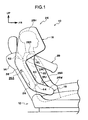
Fig. 1 is a side view showing a state in which a side airbag is inflated and deployed at the side of a passenger, as seen from a vehicle outer side, in a side airbag device for a vehicle. -
Fig. 2 is a side view showing the state in which the side airbag is inflated and deployed at the side of the passenger, as seen from a vehicle inner side. -
Fig. 3 is a sectional view showing, in a partial cross-section, the state at the first stage of restraint in which the side airbag is inflated and deployed between the passenger and a side door and restraint of the passenger by the side airbag has started, as seen from a vehicle front side. -
Fig. 4 is a sectional view showing, in a partial cross-section, the state at the latter stage of restraint in which restraint of the passenger by the side airbag has advanced further from the state ofFig. 3 . -
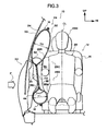
Fig. 5 through Fig. 7 relate to modified example 1, andFig. 5 is a perspective view showing the side airbag that is inflated and deployed. -
Fig. 6 is an enlarged perspective view showing a state in which a lower check valve is closed. -
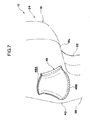
Fig. 7 is an enlarged perspective view showing a state in which an upper check valve is closed. -
Fig. 8 andFig. 9 relate to modified example 2, andFig. 8 is a perspective view showing the side airbag that is inflated and deployed. -
Fig. 9 is a plan view showing a state in which a shoulder portion of the passenger has entered-into and is restrained by a valley portion of an upper bag portion. -
Fig. 10 is a side view showing a state in which the side airbag relating to modified example 3 is inflated and deployed at the side of the passenger. -
Fig. 11 is a side view showing a state in which the side airbag relating to modified example 4 is inflated and deployed at the side of the passenger. -
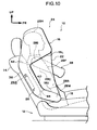
Fig. 12 through Fig. 14 relate to modified example 5, andFig. 12 is a side view showing a state in which the side airbag is inflated and deployed at the side of the passenger. -
Fig. 13 is an enlarged perspective view showing a diffuser and an inflator. -
Fig. 14 is an enlarged perspective view showing a modified example of the diffuser, and the inflator. - Embodiments of the present invention are described hereinafter on the basis of the drawings. In
Fig. 1 through Fig. 4 , aside airbag device 10 for a vehicle relating to the present embodiments relates to, for example, a side airbag device that is installed in the side portion of a seat back 14 at avehicle seat 12, and has aside airbag 24 having anupper bag portion 16, alower bag portion 18 and anintermediate portion 22. - As shown in
Fig. 3 , theside airbag 24 is configured so as to, at the time of a side collision, receive a supply of gas for inflation from an inflator 26 for example, and inflate and deploy between apassenger 28 and aside door 30 that is an example of a vehicle body side portion. At theside airbag 24, theupper bag portion 16, thelower bag portion 18, theintermediate portion 22, and a tubularinflated portion 38 that is described later are configured integrally due to, for example, a passengerside base cloth 32 and a doorside base cloth 34 being sewn. The passengerside base cloth 32 and the doorside base cloth 34 are configured by using, for example, non-extendable materials. Note that theside airbag 24 is not limited to being manufactured by sewing, and may be made by bag-weaving. - From
Fig. 1 to Fig. 4 , theupper bag portion 16 is positioned at the vehicle upper side, and corresponds to ahead portion 28H to ashoulder portion 28S of thepassenger 28 seated in thevehicle seat 12, and is an inflating portion that inflates toward the vehicle transverse direction outer side (theside door 30 side) of a region from thehead portion 28H to theshoulder portion 28. As shown inFig. 2 , avent hole 36 for example is provided in theupper bag portion 16. In the present embodiment, when theshoulder portion 28S is restrained by theupper bag portion 16, due to theupper bag portion 16 being pushed from vehicle transverse direction both sides by thepassenger 28 and theside door 30, gas within theupper bag portion 16 is discharged-out through thevent hole 36. Due thereto, it is configured such that the load, that is inputted from theupper bag portion 16 to theshoulder portion 28S toward the vehicle transverse direction inner side, decreases at the latter stage of the restraint of the shoulder portion 285. - To describe further, it is desirable to provide the
vent hole 36 at a position that does not overlap thepassenger 28 or theside door 30 in the vehicle transverse direction (at a position that is further upward than a door trim 31), in order for thevent hole 36 to not be blocked at the time of restraint of thepassenger 28. In order to make the load, that is inputted from theupper bag portion 16 to theshoulder portion 28S toward the vehicle transverse direction inner side, decrease at the latter stage of restraint of theshoulder portion 28S, it is desirable that thevent hole 36 be formed at a position, of theupper bag portion 16, at which the time of the arrival of gas from the inflator 26 is late. In consideration of these points, thevent hole 36 is formed, for example, at one place at the lower end portion of the vehicle front side, of the vehicle transverse direction inner side portion of theupper bag portion 16. - Note that the position, shape and number of the
vent hole 36 are not limited to the illustrated example. Further, as a structure that is equivalent to thevent hole 36, a non-sewn portion (not illustrated) may be provided at a portion of the sewn portion of the passengerside base cloth 32 and the doorside base cloth 34 at theupper bag portion 16, or a planned opening portion (not illustrated), that opens when the internal pressure of theupper bag portion 16 becomes greater than or equal to a predetermined value, may be provided. - From
Fig. 1 to Fig. 4 , thelower bag portion 18 is positioned at the vehicle lower side of theupper bag portion 16, and corresponds to awaist portion 28W of thepassenger 28, and is an inflated portion that inflates at the vehicle transverse direction outer side (theside door 30 side) of thewaist portion 28W. As shown inFig. 1 , the inflated shape of thelower bag portion 18 in a vehicle side view is set so as to be able to restrain at least the central position (not illustrated) of the pelvis. This is because the volume of theside airbag 24 is reduced, an inflator that is compact and has a small output can be used as the inflator 26, and the increase in cost can be suppressed. - As shown in
Fig. 3 , in the vehicle transverse direction, an inflated thickness TU of theupper bag portion 16 when theside airbag 24 is inflated and deployed is set to be thicker than an inflated thickness TL of thelower bag portion 18. Further, the internal pressure of thelower bag portion 18 when theside airbag 24 is inflated and deployed is set to be higher than the internal pressure of theupper bag portion 16. Moreover, thelower bag portion 18 is set to have, for example, a smaller volume than theupper bag portion 16 such that inflation and deployment thereof is completed before that of theupper bag portion 16 when theside airbag 24 inflates and deploys. - From
Fig. 1 to Fig. 4 , theintermediate portion 22 connects alower edge portion 16L of theupper bag portion 16 and anupper edge portion 18U of thelower bag portion 18, and is a region corresponding to achest portion 28C of thepassenger 28, and is configured as a film-shaped non-inflating portion by, for example, the passengerside base cloth 32 and the doorside base cloth 34 being superposed. As shown inFig. 1 , thisintermediate portion 22 is set so as to, for example, deploy at the region from the central portion of thechest portion 28C to the back side of thepassenger 28, as seen in a vehicle side view. Note that thisintermediate portion 22 is not limited to a non-inflating portion, and may be a thin inflated portion whose inflated thickness in the vehicle transverse direction is smaller than theupper bag portion 16 and the lower bag portion 18: - As shown in
Fig. 1 , the tubularinflated portion 38, that communicates with the vehicle rear side of theupper bag portion 16 at anend portion 42 at the vehicle upper side, and communicates with the vehicle rear side of thelower bag portion 18 at anend portion 44 at the vehicle lower side, and inflates along the spine direction of thepassenger 28 at the initial stage of inflation and deployment of theside airbag 24, is provided at theside airbag 24. - Concretely, when the
side airbag 24 inflates and deploys, theend portion 42 at the vehicle upper side of the tubularinflated portion 38 is positioned, for example, at a height in a vicinity of theshoulder portion 28S of thepassenger 28, and theend portion 44 at the vehicle lower side is positioned, for example, at a height in a vicinity of anabdomen portion 28A of thepassenger 28. Further, a reinforcingcloth 40, that is tubular for example, is sewn to the inner surface of the tubularinflated portion 38. Moreover, the upper end of this reinforcingcloth 40 is theend portion 42 at the vehicle upper side of the tubularinflated portion 38 that communicates with the vehicle rear side of theupper bag portion 16, and the lower end of the reinforcingcloth 40 is theend portion 44 at the vehicle lower side of thetubular reinforcing portion 38 that communicates with the vehicle rear side of thelower bag portion 18. - The
tubular inflator 26, at which gas ejection holes 26A are disposed at the vehicle upper side, is provided within the tubularinflated portion 38. Accordingly, gas that is ejected from the gas ejection holes 26A when the inflator 26 operates, is first supplied into the tubularinflated portion 38. Due thereto, the deployment behaviors of theupper bag portion 16 and thelower bag portion 18 thereafter are stable. Further, due to the tubularinflated portion 38 inflating and the internal pressure thereof increasing earlier, a core region of high pressure at theside airbag 24 is formed. Due to this tubularinflated portion 38, it is also possible to restrain the spine, for example, of thepassenger 28 at the initial stage of the side collision that is earlier than the completion of the inflation and deployment of theside airbag 24. - Although not illustrated, the
inflator 26 is fixed to an unillustrated seat back frame, and is connected to an airbag ECU via a wire harness, and is configured so as to operate by operation current from the airbag ECU and supply gas for inflation to theside airbag 24. The airbag ECU is configured so as to cause operation current to flow to the inflator 26 when the airbag ECU judges a side collision due to a signal from a collision sensor (not illustrated). - The present embodiment is configured as described above, and operation thereof is described hereinafter. From
Fig. 1 to Fig. 4 , at theside airbag device 10 for a vehicle relating to the present embodiment, when side collision load F (Fig. 3 ,Fig. 4 ) is inputted to theside door 30 that is a vehicle body side portion, when the airbag ECU judges the occurrence of the side collision on the basis of a signal from an unillustrated collision sensor, operation current is made to flow from the airbag ECU to theinflator 26. The inflator 26 receives the operation current and operates, and a causes a large amount of gas to be ejected from the gas ejection holes 26A. Due to this gas being supplied into theside airbag 24, theside airbag 24 swells-out from the seat back 14, and inflates and deploys between thepassenger 28 and theside door 30. Of thisside airbag 24, theupper bag portion 16 enters into the gap between, for example, aglass 33 of theside door 30 and thepassenger 28, and inflates and deploys, and thelower bag portion 18 enters into the gap between, for example, the door trim 31 of theside door 30 and thepassenger 28, and inflates and deploys. Then, from thehead portion 28H to theshoulder portion 28S is restrained by theupper bag portion 16, and thewaist portion 28W is restrained by thelower bag portion 18, and further, thechest portion 28C and theabdomen portion 28A can be restrained by theintermediate portion 22 that connects the lower edge portion of theupper bag portion 16 and the upper edge portion of thelower bag portion 18. - Concretely, because the inflator 26 is provided within the tubular
inflated portion 38. that is reinforced by the reinforcingcloth 40, the gas that is ejected from thegas ejection holes 26A is first supplied into the tubularinflated portion 38. Due thereto, at the initial stage of inflation and deployment of theside airbag 24, the tubularinflated portion 38 inflates along the spine direction of thepassenger 28. Due to this tubularinflated portion 38, the spine of thepassenger 28 can be restrained at the initial stage of the side collision that is earlier than the completion of the inflation and deployment of theside airbag 24. - Further, because the tubular
inflated portion 38 becomes a core region of high pressure at theside airbag 24 at the initial stage of inflation and deployment, the deployment behaviors of theupper bag portion 16 and thelower bag portion 18 thereafter are stable.
Due thereto, theupper bag portion 16 receives a supply of gas from theend portion 42 at the vehicle upper side of the tubularinflated portion 38, and theupper bag portion 16 deploys stably at the region corresponding to thehead portion 28H to theshoulder portion 28S of thepassenger 28. Further, thelower bag portion 18 receives a supply of gas from theend portion 44 at the vehicle lower side of the tubularinflated portion 38, and deploys stably at the region corresponding to thewaist portion 28W of thepassenger 28. - Here, as shown in
Fig. 3 , the inflated thickness TU of theupper bag portion 16 when theside airbag 24 is inflated and deployed is set to be thicker than the inflated thickness TL of thelower bag portion 18. Therefore, thehead portion 28H, that is positioned further toward the vehicle transverse direction inner side than theshoulder portion 28S and thewaist portion 28W, can be restrained appropriately by theupper bag portion 16. - Further, due to the
shoulder portion 28S being pushed toward the vehicle transverse direction inner side at the initial stage of restraint of thepassenger 28 by theupper bag portion 16, the load to thechest portion 28C can be reduced. When the restraint of theshoulder portion 28S by theupper bag portion 16 advances, theupper bag portion 16 is pressed from vehicle transverse direction both sides by thepassenger 28 and theside door 30, and therefore, gas within theupper bag portion 16 is discharged-out through the vent hole 36 (Fig. 2 ). Due thereto, the load, that is imparted toward the vehicle transverse direction inner side from theupper bag portion 16 to theshoulder portion 28S of thepassenger 28, decreases at the latter stage of restraint of theshoulder portion 28S by theupper bag portion 16, and therefore, the amount of movement of theshoulder portion 28S toward the vehicle transverse direction inner side can be suppressed to an appropriate degree. Because thevent hole 36 is provided, for example, at one place at the lower end portion of the vehicle front side of the vehicle transverse direction inner side portion of theupper bag portion 16, the flowing-out of gas in the inflating and deploying process of theupper bag portion 16 is suppressed. Due thereto, the initial internal pressure of theupper bag portion 16 can be increased sufficiently. - Next, because the internal pressure of the
lower bag portion 18 is set to be higher than the internal pressure of theupper bag portion 16, even if the inflated thickness of thelower bag portion 18 is thinner than theupper bag portion 16, thewaist portion 28W of thepassenger 28 can be restrained appropriately by thelower bag portion 18. - The volume of the
lower bag portion 18 is set to an extent such that at least the central position (not illustrated) of the pelvis in a vehicle side view can be restrained, and inflation and deployment are completed before theupper bag portion 16. Therefore, thewaist portion 28W of thepassenger 28 is restrained at an earlier stage than theshoulder portion 28S and thehead portion 28H. Due to thewaist portion 28W, at which the strength is relatively great among the upper body of thepassenger 28, being restrained at an early stage than thelower bag portion 18 and being moved toward the vehicle transverse direction inner side, the respective portions of the upper body of thepassenger 28, including thewaist portion 28W, can be restrained even more appropriately by theside airbag 24. - Concretely, as shown in
Fig. 4 , when restraint of the upper body by theside airbag 24 is completed, a central line CL of the upper body as seen from the front of thepassenger 28 is maintained substantially rectilinearly even while tilting with respect to the vehicle vertical direction, and therefore, the posture of thepassenger 28 does not vary greatly. - Further, the
intermediate portion 22 is a non-inflating portion that is film-shaped and whose thickness is thinner than theupper bag portion 16 and thelower bag portion 18. Therefore, the load that is inputted from theintermediate portion 22 to thechest portion 28C can be decreased due to thechest portion 28C of thepassenger 28 being restrained by theintermediate portion 22 after theshoulder portion 28S is pushed by theupper bag portion 16 earlier. - In this way, in accordance with the
side airbag device 10 for a vehicle relating to the present embodiment, the posture of thepassenger 28 at the time of a side collision can be controlled appropriately by theside airbag 24 that is integral. - The tubular
inflated portion 38 can also be made to be the structure of modified example 1 shown inFig. 5 . In this modified example 1, alower check valve 46, which permits passage of gas to thelower bag portion 18 side and restricts passage of gas in the direction opposite thereto, is provided at theend portion 44 at the vehicle lower side of the tubularinflated portion 38, and anupper check valve 48, which permits passage of gas to theupper bag portion 16 side and restricts passage of gas in the direction opposite thereto, is provided at theend portion 42 at the vehicle upper side of the tubularinflated portion 38. - The
lower check valve 46 and theupper check valve 48 are configured by, for example, base cloths that are flexible being sewn in the shapes of funnels that taper respectively toward openingportion inflated portion 38 atbase end portions lower check valve 46 andupper check valve 48 are configured such that the gas that is supplied from the inflator 26 into the tubularinflated portion 38 is distributed in accordance with the respective volumes and internal pressure settings of theupper bag portion 16 and thelower bag portion 18. - Concretely, at the
lower check valve 46, the flow path opening surface area of theopening portion 46A is set to be relatively small in accordance with the volume of thelower bag portion 18. Due thereto, flowing-in of gas from the tubularinflated portion 38 into thelower bag portion 18 that has a relatively small volume is suppressed, the inflation timing of thelower bag portion 18 is delayed, and flowing-in of gas into theupper bag portion 16 can be promoted. - Further, a
flow path length 46L of thelower check valve 46 is set to be relatively small in consideration of the timing of restraining thewaist portion 28W of thepassenger 28 by thelower bag portion 18. When theflow path length 46L is small, it is difficult for the base cloth of thelower check valve 46 to bend. Accordingly, when the supply of gas to thelower bag portion 18 ends and gas attempts to flow backward from thelower bag portion 18 to the tubularinflated portion 38 side, and concretely, when the internal pressure of thelower bag portion 18 becomes higher than the internal pressure of the tubularinflated portion 38 due to the restraint of thewaist portion 28W of thepassenger 28, theopening portion 46A of thelower check valve 46 closes relatively slowly as shown inFig. 6 . - The internal pressure of the
lower bag portion 18 can be maintained over a longer time while the supplying of gas to theupper bag portion 16 is promoted, by restricting the backward flow of gas while delaying the closing timing of thelower check valve 46 in this way. Further, thewaist portion 28W (seeFig. 1 ,Fig. 4 ) of thepassenger 28 can be restrained appropriately by thislower bag portion 18. - On the other hand, at the
upper check valve 48, the flow path opening surface area of theopening portion 48A is set to be relatively large in accordance with the volume of theupper bag portion 16. Due thereto, flowing-in of gas from the tubularinflated portion 38 to theupper bag portion 16 that has a relatively large volume is promoted, and the inflation timing of theupper bag portion 16 can be advanced, and flowing-in of gas to thelower bag portion 18 that has a relatively small volume can be suppressed. - Further, a
flow path length 48L of theupper check valve 48 is set to be relatively large in consideration of the timing of restraint of theshoulder portion 28S and thehead portion 28H of thepassenger 28 by theupper bag portion 16. When theflow path length 48L is large, it is easy for the base cloth of theupper check valve 48 to bend. Accordingly, when the supply of gas to theupper bag portion 16 ends and gas attempts to flow backward from theupper bag portion 16 to the tubularinflated portion 38 side, and concretely, when the internal pressure of theupper bag portion 16 becomes higher than the internal pressure of the tubularinflated portion 38 due to the restraint of theshoulder portion 28S and thehead portion 28H of thepassenger 28, theopening portion 48A of theupper check valve 48 closes relatively quickly as shown inFig. 7 . - The internal pressure of the
upper bag portion 16 can be maintained over a longer time, by restricting the backward flow of gas while advancing the closing timing of theupper check valve 48 in this way. Further, theshoulder portion 28S and thehead portion 28H (seeFig. 1 ,Fig. 4 ) of thepassenger 28 can be restrained appropriately by thisupper bag portion 16. - As described above, in accordance with the
side airbag device 10 for a vehicle relating to modified example 1, by setting the flow path opening surface areas of the openingportions flow path lengths lower check valve 46 and theupper check valve 48, the gas that is supplied into the tubularinflated portion 38 can be distributed in accordance with the respective volumes and internal pressure settings of theupper bag portion 16 and thelower bag portion 18. Therefore, theupper bag portion 16 and thelower bag portion 18 can respectively be inflated and deployed at desired timings, and, after the gas is supplied, theupper bag portion 16 and thelower bag portion 18 can respectively be maintained at the desired internal pressures. - In
Fig. 8 , the tubularinflated portion 38 can also be made to be the structure of modified example 2 shown inFig. 8 . In this modified example 2, atether 50, that restricts the inflated thickness of theupper bag portion 16, is provided within theupper bag portion 16. Thistether 50 is sewn respectively to the passengerside base cloth 32 and the doorside base cloth 34 atend edges 50A at the vehicle transverse both sides, and extends, for example, along the longitudinal direction of the tubularinflated portion 38. Although the front-rear position of thetether 50 is arbitrary, it is preferably a front-rear position that corresponds to theshoulder portion 28S or thehead portion 28H of thepassenger 28 as shown inFig. 9 . - As shown in
Fig. 8 , apredetermined gap 52 is provided between anupper end 50U of thetether 50 and anupper edge portion 16U of theupper bag portion 16, and apredetermined gap 54 is provided also between alower end 50L of thetether 50 and thelower edge portion 16L of theupper bag portion 16. Theupper bag portion 16 interior is divided by thistether 50 into aregion 56 at the vehicle front side and aregion 58 at the vehicle rear side, and theregion 58 at the vehicle rear side also serves as the upper portion of the tubularinflated portion 38. Accordingly, when theside airbag 24 inflates and deploys, the tubularinflated portion 38 inflates to an even higher position, along the spine direction of the passenger 28 (seeFig. 1 ). - Of the
upper bag portion 16, theregion 56 at the vehicle front side of thetether 50 inflates and deploys due to gas, that is within theregion 58 at the vehicle rear side, flowing-in through thegaps tether 50. By doing so, the inflated thickness of theupper bag portion 16 that is inflated and deployed is restricted by thetether 50. Concretely, at the positions of the end edges 50A of thetether 50 that are sewn to the passengerside base cloth 32 and the doorside base cloth 34, by making the inflated thickness of theupper bag portion 16 partially small,valley portions 60, that run along the longitudinal directions of the end edges 50A of thetether 50, are formed at the vehicle transverse direction both sides of theupper bag portion 16. Accordingly, as shown inFig. 9 , when thetether 50 is provided at a front-rear position that corresponds to theshoulder portion 28S or thehead portion 28H of thepassenger 28, thepassenger 28 can be restrained more stably due to theshoulder portion 28S or thehead portion 28H entering-into thevalley portion 60. - Note that, although a state in which the
shoulder portion 28S is restrained at thevalley portion 60 of theupper bag portion 16 is illustrated inFig. 9 , thehead portion 28H as well can similarly be restrained at thevalley portion 60 of theupper bag portion 16. - The
intermediate portion 22 can also be made to be the structure of modified example 3 shown inFig. 10 . In this modified example 3, the front edge of theintermediate portion 22 is formed so as to connect the front end of thelower edge portion 16L of theupper bag portion 16 and the front end of theupper edge portion 18U of thelower bag portion 18. In other words, the region of theintermediate portion 22 is deployed toward the vehicle front side to a region that corresponds to afront portion 28F of thechest portion 28C of thepassenger 28. - By deploying the region of the
intermediate portion 22 toward the vehicle front side in this way, at the time of a side collision, thefront portion 28F, at which the strength is relatively great among thechest portion 28C of thepassenger 28, can be stably restrained by theintermediate portion 22. Further, theabdomen portion 28A of thepassenger 28 also can be restrained by theintermediate portion 22. - The
intermediate portion 22 can also be made to be the structure of modified example 4 shown inFig. 11 . In this modified example 4, anextended bag portion 16E, that extends to the region corresponding to thefront portion 28F of thechest portion 28C of thepassenger 28, is provided at the vehicle front side lower end edge of theupper bag portion 16. Further, theintermediate portion 22 also is deployed toward the vehicle front side, in the same way as modified example 3. - Due thereto, at the time of a side collision, the
front portion 28F, at which the strength is relatively great among thechest portion 28C of thepassenger 28, can be restrained by thisextended bag portion 16E. Therefore, the load, that is inputted to thepassenger 28 when thepassenger 28 is restrained by theside airbag 24, can be dispersed. Further, due thereto, input of load to a region, at which the strength is relatively small, of thepassenger 28 can be suppressed. - As in modified example 5 that is shown in
Fig. 12 , adiffuser 62, which directs the flow of gas that is ejected from the gas ejection holes 26A toward theupper bag portion 16 side and thelower bag portion 18 side, may be provided at theinflator 26. Thisdiffuser 62 is, together with the inflator 26 for example, fixed to a seat backframe 64 that is the skeleton of the seat back 14. - For example, two
stud bolts 26B are provided at the inflator 26 so as to stand in a direction orthogonal to the axial direction of theinflator 26. Thesestud bolts 26B pass-through alower portion 62B of thediffuser 62 and project-out. Due to thestud bolts 26B being passed-through the seat backframe 64 and being fastened by nuts (not illustrated), theinflator 26 and thediffuser 62 are fastened and fixed to the seat backframe 64. - As shown in
Fig. 13 , thediffuser 62 is configured to have anupper portion 62A that is cylindrical-tube-shaped and that has a larger diameter than the inflator 26, thelower portion 62B that is connected with the lower side of the rear portion of theupper portion 62A, and atop wall portion 62D that is joined to the rear portion of the top end of theupper portion 62A. - Generally, when the inflator 26 operates, gas is ejected in a radial form in the radial direction of the inflator 26 from the gas ejection holes 26A. However, due to this gas being received at the
upper portion 62A that is cylindrical-tube-shaped, the flow of gas can be restricted to the axial direction of theinflator 26. This gas flows in an arrow A direction toward the upper bag portion 16 (Fig. 12 ), and flows in an arrow B direction toward the lower bag portion 18 (Fig. 12 ). Thelower portion 62B of thediffuser 62 is configured with a portion of a cylindrical tube, that has the same curvature as theupper portion 62A for example, being a curved portion that extends toward the axial direction lower side of the inflator 26, and, in addition to performing as a fixing portion to the seat back frame 64 (Fig. 12 ), also performs as a guide plate that guides gas in the arrow B direction. - The
top wall portion 62D is configured so as to open slightly toward the vehicle upper side due to a joinedportion 62E with theupper portion 62A deforming due to the pressure of the gas that is ejected from the gas ejection holes 26A of theinflator 26. Due to thetop wall portion 62D opening, anopening portion 62C is formed at the upper end of theupper portion 62A, and gas flows in the arrow A direction from theopening portion 62C toward theupper bag portion 16 side (seeFig. 12 ). - To describe further, the flowing direction of the gas can be controlled by an opening angle D of the
top wall portion 62D at this time. If the opening angle D of thetop wall portion 62D is set to be large, the flow of gas can be directed toward the vehicle upper side. Further, if the opening angle D of thetop wall portion 62D is set to be small, the flow of gas can be directed toward the vehicle front side. Accordingly, the way that theupper bag portion 16 inflates and deploys, that is what region of theupper bag portion 16 is to be inflated preferentially, can also be controlled by the settings of thediffuser 62. - The structure of the
diffuser 62 is not limited to this, and for example, may be a structure in which thetop wall portion 62D is not provided as shown inFig. 14 . - In this way, in the
side airbag device 10 for a vehicle relating to modified example 5, the flow of the gas that is ejected from the gas ejection holes 26A of the inflator 26 can be directed toward theupper bag portion 16 side and thelower bag portion 18 side by thediffuser 62 that is provided at theinflator 26. Therefore, theupper bag portion 16 and thelower bag portion 18 can respectively be inflated and deployed appropriately by using the general-purpose inflator 26 that has the gas ejection holes 26A at one end thereof. - Although the illustrated example describes that the
side airbag device 10 for a vehicle is provided at the side portion of the seat back 14, theside airbag device 10 for a vehicle is not limited to this, and may be provided at the inner side of the door trim 31 at theside door 30. Further, although theside door 30 is presented as the vehicle body side portion, the vehicle body side portion is not limited to this, may be a region of the vehicle body that is positioned at the side of the passenger, and also includes a non-door portion. -
- 10
- side airbag device for a vehicle
- 12
- vehicle seat
- 14
- seat back
- 16
- upper bag portion
- 16E
- extended bag portion
- 16L
- lower edge portion
- 18
- lower bag portion
- 18U
- upper edge portion
- 22
- intermediate portion
- 24
- side airbag
- 26
- inflator
- 26A
- gas ejection hole
- 28
- passenger
- 28C
- chest portion
- 28F
- front portion
- 28H
- head portion
- 28S
- shoulder portion
- 28W
- waist portion
- 30
- side door (vehicle body side portion)
- 36
- vent hole
- 38
- tubular inflated portion
- 42
- end portion at vehicle upper side
- 44
- end portion at vehicle lower side
- 46
- lower check valve
- 48
- upper check valve
- 62
- diffuser
Claims (8)
- A side airbag device comprising:a side airbag comprising:an upper bag portion that is positioned at a vehicle upper side, and corresponds to a head portion to a shoulder portion of a passenger seated in a vehicle seat;a lower bag portion that is positioned at a vehicle lower side of the upper bag portion, and corresponds to a waist portion of the passenger; andan intermediate portion that connects a lower edge portion of the upper bag portion and an upper edge portion of the lower bag portion, and corresponds to a chest portion of the passenger, wherein:at a time of a side collision, the side airbag receives a supply of gas for inflation and inflates and deploys between the passenger and a vehicle body side portion; andthe side airbag device is configured such that a load, that is imparted toward a vehicle transverse direction inner side from the upper bag portion to the shoulder portion when the shoulder portion is restrained by the upper bag portion, decreases at a latter stage of restraint of the shoulder portion.
- The side airbag device for a vehicle of Claim 1, wherein a tubular inflated portion is provided that communicates with a vehicle rear side of the upper bag portion at an end portion at a vehicle upper side, and communicates with a vehicle rear side of the lower bag portion at an end portion at a vehicle lower side, and inflates along a spine direction of the passenger at an initial stage of inflation and deployment of the side airbag.
- The side airbag device for a vehicle of Claim 2, wherein:a tubular inflator, at which gas ejection holes are disposed at a vehicle upper side, is provided within the tubular inflated portion; anda diffuser, which directs a flow of gas that is ejected from the gas ejection holes toward the upper bag portion side and the lower bag portion side, is provided at the inflator.
- The side airbag device for a vehicle of Claim 2 or Claim 3, wherein:an inflated thickness of the upper bag portion when the side airbag inflates and deploys is set to be thicker than an inflated thickness of the lower bag portion;an internal pressure of the lower bag portion is set to be higher than an internal pressure of the upper bag portion; andthe lower bag portion is configured such that inflation and deployment thereof are completed before that of the upper bag portion.
- The side airbag device for a vehicle of Claim 4, wherein a lower check valve, which permits passage of gas toward the lower bag portion side and restricts passage of gas in a direction opposite thereto, is provided at the end portion at the vehicle lower side of the tubular inflated portion.
- The side airbag device for a vehicle of Claim 5, wherein an upper check valve, which permits passage of gas toward the upper bag portion side and restricts passage of gas in a direction opposite thereto, is provided at the end portion at the vehicle upper side of the tubular inflated portion.
- The side airbag device for a vehicle of Claim 6, wherein flow path opening surface areas and flow path lengths of the lower check valve and the upper check valve are configured such that gas that is supplied into the tubular inflated portion is distributed in accordance with respective volumes and internal pressure settings of the upper bag portion and the lower bag portion.
- The side airbag device for a vehicle of any one of Claim 1 through Claim 7, wherein an extended bag portion, that extends to a region corresponding to a front portion of the chest portion of the passenger, is provided at a vehicle front side lower end edge of the upper bag portion.
Applications Claiming Priority (1)
| Application Number | Priority Date | Filing Date | Title |
|---|---|---|---|
| PCT/JP2009/063763 WO2011016107A1 (en) | 2009-08-03 | 2009-08-03 | Side airbag device for vehicle |
Publications (3)
| Publication Number | Publication Date |
|---|---|
| EP2463159A1 true EP2463159A1 (en) | 2012-06-13 |
| EP2463159A4 EP2463159A4 (en) | 2012-12-26 |
| EP2463159B1 EP2463159B1 (en) | 2013-10-30 |
Family
ID=43544029
Family Applications (1)
| Application Number | Title | Priority Date | Filing Date |
|---|---|---|---|
| EP09848040.3A Not-in-force EP2463159B1 (en) | 2009-08-03 | 2009-08-03 | Side airbag device for vehicle |
Country Status (5)
| Country | Link |
|---|---|
| US (1) | US8448981B2 (en) |
| EP (1) | EP2463159B1 (en) |
| JP (1) | JP5423797B2 (en) |
| CN (1) | CN102470818B (en) |
| WO (1) | WO2011016107A1 (en) |
Cited By (2)
| Publication number | Priority date | Publication date | Assignee | Title |
|---|---|---|---|---|
| EP3118067A4 (en) * | 2014-03-13 | 2017-11-08 | Mitsubishi Jidosha Kogyo Kabushiki Kaisha | Side air bag device for vehicle |
| WO2019110705A1 (en) * | 2017-12-08 | 2019-06-13 | Trw Automotive Gmbh | Side airbag and vehicle-occupant restraint system having a side airbag |
Families Citing this family (51)
| Publication number | Priority date | Publication date | Assignee | Title |
|---|---|---|---|---|
| CN102834303B (en) * | 2010-11-17 | 2015-07-01 | 丰田自动车株式会社 | Side airbag device for vehicle |
| US8480124B2 (en) * | 2011-01-18 | 2013-07-09 | Autoliv Asp, Inc. | Seat bolster chamber |
| US9238425B2 (en) | 2011-12-28 | 2016-01-19 | Toyota Jidosha Kabushiki Kaisha | Vehicle seat |
| JP5724908B2 (en) * | 2012-03-09 | 2015-05-27 | 豊田合成株式会社 | Side airbag device |
| KR101585096B1 (en) * | 2012-03-14 | 2016-01-22 | 아우토리브 디벨롭먼트 아베 | Side airbag module for vehicle |
| JP5776616B2 (en) * | 2012-04-16 | 2015-09-09 | トヨタ自動車株式会社 | Vehicle seat |
| JP5594327B2 (en) | 2012-07-10 | 2014-09-24 | トヨタ自動車株式会社 | Vehicle seat |
| JP5692178B2 (en) * | 2012-07-23 | 2015-04-01 | トヨタ自動車株式会社 | Side airbag device for vehicle |
| JP5776648B2 (en) * | 2012-08-10 | 2015-09-09 | トヨタ自動車株式会社 | Crew protection device |
| JP5594340B2 (en) * | 2012-09-05 | 2014-09-24 | トヨタ自動車株式会社 | Vehicle safety device |
| US20140103625A1 (en) * | 2012-10-15 | 2014-04-17 | Tk Holdings Inc. | Parachute airbag diffuser |
| JP5942772B2 (en) * | 2012-10-18 | 2016-06-29 | トヨタ自動車株式会社 | Vehicle seat with side airbag device |
| US8851511B1 (en) * | 2013-06-03 | 2014-10-07 | Key Safety Systems, Inc. | Shaped airbag |
| US9139153B2 (en) * | 2013-09-05 | 2015-09-22 | Ford Global Technologies, Llc | Vehicle side impact airbag with laterally extending thoracic chamber |
| CA2886916A1 (en) * | 2013-09-27 | 2015-04-02 | Toyota Jidosha Kabushiki Kaisha | Vehicle side airbag device and vehicle seat |
| US9108587B2 (en) * | 2013-10-08 | 2015-08-18 | Autoliv Asp, Inc. | 3-layer “C” shaped side airbag |
| JP6183184B2 (en) * | 2013-11-29 | 2017-08-23 | 三菱自動車工業株式会社 | Side airbag device |
| JP5879380B2 (en) * | 2014-03-28 | 2016-03-08 | 富士重工業株式会社 | Airbag device |
| DE102014209664A1 (en) * | 2014-05-21 | 2015-11-26 | Ford Global Technologies, Llc | Side airbag device for vehicles |
| JP6380161B2 (en) * | 2014-09-12 | 2018-08-29 | 豊田合成株式会社 | Side airbag device |
| US9505369B2 (en) * | 2014-09-12 | 2016-11-29 | Toyoda Gosei Co., Ltd. | Side airbag apparatus |
| JP6197777B2 (en) * | 2014-10-10 | 2017-09-20 | トヨタ自動車株式会社 | Far-side airbag device for vehicles |
| JP6191574B2 (en) * | 2014-10-10 | 2017-09-06 | トヨタ自動車株式会社 | Far-side airbag device for vehicles |
| JP6183332B2 (en) * | 2014-11-06 | 2017-08-23 | トヨタ自動車株式会社 | Far side airbag device |
| JP6575758B2 (en) * | 2015-10-14 | 2019-09-18 | 三菱自動車工業株式会社 | Side airbag device |
| US9827940B2 (en) * | 2016-03-16 | 2017-11-28 | Autoliv Asp, Inc. | Side airbag with internal diffuser |
| JP6583145B2 (en) * | 2016-06-03 | 2019-10-02 | 豊田合成株式会社 | Airbag device |
| JP6835315B2 (en) * | 2017-05-18 | 2021-02-24 | 株式会社ダイセル | Gas generator and storage container |
| US10407017B2 (en) * | 2017-06-09 | 2019-09-10 | Honda Motor Co., Ltd. | Vehicle side airbag system, and methods of use and manufacture thereof |
| US10336278B2 (en) * | 2017-07-14 | 2019-07-02 | Autoliv Asp, Inc. | Inflatable airbag harness assemblies |
| DE102017218338A1 (en) * | 2017-10-13 | 2019-04-18 | Bayerische Motoren Werke Aktiengesellschaft | AIRBAG ARRANGEMENT FOR A VEHICLE SEAT OF A MOTOR VEHICLE |
| US10703321B2 (en) * | 2017-11-20 | 2020-07-07 | Ford Global Technologies, Llc | Airbag assembly |
| US10703325B2 (en) * | 2017-11-27 | 2020-07-07 | Autoliv Asp, Inc. | Multi-chambered side airbag assemblies |
| JP2019111916A (en) * | 2017-12-22 | 2019-07-11 | トヨタ自動車株式会社 | Vehicle side airbag device |
| JP6596757B2 (en) * | 2017-12-28 | 2019-10-30 | 本田技研工業株式会社 | Airbag device |
| EP3744579B1 (en) * | 2018-01-26 | 2024-05-15 | Autoliv Development AB | Side air bag device and vehicle seat with same |
| KR102064843B1 (en) * | 2018-04-23 | 2020-01-10 | 아우토리브 디벨롭먼트 아베 | Airbag apparatus of vehicle |
| US10988100B2 (en) | 2019-08-29 | 2021-04-27 | Ford Global Technologies, Llc | Side airbag including non-expandable region |
| JP7192725B2 (en) * | 2019-09-25 | 2022-12-20 | 豊田合成株式会社 | side airbag device |
| JP7532065B2 (en) * | 2020-03-30 | 2024-08-13 | マツダ株式会社 | Side airbag device |
| JP7372867B2 (en) * | 2020-03-30 | 2023-11-01 | 芦森工業株式会社 | side airbag device |
| JP7384776B2 (en) * | 2020-10-22 | 2023-11-21 | トヨタ自動車株式会社 | Vehicle side airbag |
| JP7380520B2 (en) | 2020-10-22 | 2023-11-15 | トヨタ自動車株式会社 | Vehicle side airbag devices and occupant protection devices |
| JP7298585B2 (en) * | 2020-10-22 | 2023-06-27 | トヨタ自動車株式会社 | Vehicle side airbag device and occupant protection device |
| JP7351284B2 (en) * | 2020-10-22 | 2023-09-27 | トヨタ自動車株式会社 | Vehicle side airbag devices and occupant protection devices |
| JP7517186B2 (en) | 2021-02-02 | 2024-07-17 | トヨタ自動車株式会社 | Vehicle side airbag device, side airbag folding method, and passenger protection device |
| DE102021110217A1 (en) * | 2021-04-22 | 2022-10-27 | Zf Automotive Germany Gmbh | Center gas bag and vehicle occupant restraint system with a center gas bag |
| JP7690379B2 (en) * | 2021-11-02 | 2025-06-10 | トヨタ自動車株式会社 | Vehicle seat and side airbag folding method |
| JP7582159B2 (en) * | 2021-11-02 | 2024-11-13 | トヨタ自動車株式会社 | Vehicle seat and side airbag folding method |
| US11752970B1 (en) | 2022-06-29 | 2023-09-12 | GM Global Technology Operations LLC | One-way multiple chambers and cushions airbag |
| JP2024061008A (en) * | 2022-10-20 | 2024-05-07 | 株式会社Subaru | Air bag device |
Family Cites Families (24)
| Publication number | Priority date | Publication date | Assignee | Title |
|---|---|---|---|---|
| DE19529829C1 (en) | 1995-08-14 | 1996-10-31 | Pars Passive Rueckhaltesysteme | Head and thorax protection air bag for vehicles |
| JPH09136595A (en) | 1995-11-15 | 1997-05-27 | Tokai Rika Co Ltd | Air bag device for side impact |
| JP3374648B2 (en) * | 1996-04-08 | 2003-02-10 | 三菱自動車工業株式会社 | Airbag for side impact |
| JP3758287B2 (en) | 1997-03-31 | 2006-03-22 | 日産自動車株式会社 | Airbag device |
| DE29822159U1 (en) * | 1998-12-11 | 1999-05-12 | Trw Repa Gmbh | Airbag side impact protection device |
| US20040124615A1 (en) * | 2001-06-08 | 2004-07-01 | Toshinori Tanase | Side air bag device |
| US20030168836A1 (en) * | 2002-03-11 | 2003-09-11 | Eiji Sato | Side airbag apparatus |
| JP4103633B2 (en) * | 2003-03-06 | 2008-06-18 | タカタ株式会社 | Side airbag device |
| US7168733B2 (en) | 2002-12-27 | 2007-01-30 | Takata Corporation | Airbag apparatus |
| WO2004065179A1 (en) | 2003-01-20 | 2004-08-05 | Toyota Jidosha Kabushiki Kaisha | Vehicle occupant protection device |
| CN100349767C (en) * | 2003-01-20 | 2007-11-21 | 丰田自动车株式会社 | occupant protection device |
| JP2005047471A (en) * | 2003-07-31 | 2005-02-24 | Toyoda Gosei Co Ltd | Method for folding air bag and air bag device |
| JP4566629B2 (en) * | 2004-06-28 | 2010-10-20 | マツダ株式会社 | Airbag device |
| JP4453966B2 (en) * | 2004-06-28 | 2010-04-21 | マツダ株式会社 | Airbag device |
| DE102005028702A1 (en) | 2004-06-28 | 2006-03-16 | Mazda Motor Corp. | Airbag device |
| JP4846595B2 (en) * | 2004-11-04 | 2011-12-28 | オートリブ ディベロップメント エービー | Side airbag device for vehicle |
| JP4552840B2 (en) * | 2005-04-01 | 2010-09-29 | 豊田合成株式会社 | Side airbag device |
| JP5007047B2 (en) * | 2006-01-13 | 2012-08-22 | 本田技研工業株式会社 | Airbag device |
| US7278656B1 (en) * | 2007-01-30 | 2007-10-09 | Key Safety Systems, Inc. | Seat mounted side impact airbag module |
| JP2009051471A (en) | 2007-08-29 | 2009-03-12 | Seiren Co Ltd | Air bag device |
| JP5125596B2 (en) * | 2008-02-22 | 2013-01-23 | 豊田合成株式会社 | Side airbag device |
| DE102009036800A1 (en) * | 2008-08-12 | 2010-02-18 | Dalphimetal España S.A. | Airbag module with gas distribution element |
| DE102008063794B4 (en) | 2008-12-17 | 2014-04-03 | TAKATA Aktiengesellschaft | Airbag for a vehicle occupant restraint system |
| JP2011020502A (en) * | 2009-07-14 | 2011-02-03 | Toyoda Gosei Co Ltd | Side air bag device |
-
2009
- 2009-08-03 WO PCT/JP2009/063763 patent/WO2011016107A1/en not_active Ceased
- 2009-08-03 JP JP2011525707A patent/JP5423797B2/en not_active Expired - Fee Related
- 2009-08-03 CN CN200980160747.0A patent/CN102470818B/en not_active Expired - Fee Related
- 2009-08-03 EP EP09848040.3A patent/EP2463159B1/en not_active Not-in-force
- 2009-08-03 US US13/384,715 patent/US8448981B2/en not_active Expired - Fee Related
Cited By (3)
| Publication number | Priority date | Publication date | Assignee | Title |
|---|---|---|---|---|
| EP3118067A4 (en) * | 2014-03-13 | 2017-11-08 | Mitsubishi Jidosha Kogyo Kabushiki Kaisha | Side air bag device for vehicle |
| US10131310B2 (en) | 2014-03-13 | 2018-11-20 | Mitsubishi Jidosha Kogyo Kabushiki Kaisha | Side airbag device for vehicle |
| WO2019110705A1 (en) * | 2017-12-08 | 2019-06-13 | Trw Automotive Gmbh | Side airbag and vehicle-occupant restraint system having a side airbag |
Also Published As
| Publication number | Publication date |
|---|---|
| WO2011016107A1 (en) | 2011-02-10 |
| US8448981B2 (en) | 2013-05-28 |
| EP2463159B1 (en) | 2013-10-30 |
| JP5423797B2 (en) | 2014-02-19 |
| EP2463159A4 (en) | 2012-12-26 |
| CN102470818A (en) | 2012-05-23 |
| JPWO2011016107A1 (en) | 2013-01-10 |
| CN102470818B (en) | 2014-03-12 |
| US20120126518A1 (en) | 2012-05-24 |
Similar Documents
| Publication | Publication Date | Title |
|---|---|---|
| EP2463159B1 (en) | Side airbag device for vehicle | |
| JP6080344B2 (en) | Airbag device | |
| US8047564B2 (en) | Airbag | |
| CN107640118B (en) | vehicle occupant restraint system | |
| EP1832475B1 (en) | Side air bag device for vehicle | |
| US8641088B2 (en) | Side-impact airbag module | |
| JP6323438B2 (en) | Vehicle seat with side airbag device | |
| KR101738555B1 (en) | Side airbag device | |
| EP2396197B1 (en) | Side airbag system and method of manufacturing side airbag | |
| CN104602972B (en) | Side air bag device for vehicle | |
| US9932011B2 (en) | Side airbag apparatus | |
| JP4434193B2 (en) | Side airbag device for vehicle | |
| US20140217707A1 (en) | Airbag device | |
| US9211863B2 (en) | Head-protecting airbag device | |
| EP3446930A1 (en) | Vehicle knee airbag device and knee airbag folding method | |
| CN110431052A (en) | occupant protection device | |
| JP2017065398A (en) | Head protection airbag device | |
| US8360467B2 (en) | Head-protecting airbag apparatus | |
| JP2003246254A (en) | Occupant protecting apparatus | |
| JP2009040265A (en) | Head protection airbag device | |
| JP2005096575A (en) | Head protective air bag | |
| JP2009286358A (en) | Vehicular airbag device | |
| JP5786785B2 (en) | Airbag device | |
| JP5617726B2 (en) | Head protection airbag device | |
| CN104369711B (en) | Side air bag device |
Legal Events
| Date | Code | Title | Description |
|---|---|---|---|
| PUAI | Public reference made under article 153(3) epc to a published international application that has entered the european phase |
Free format text: ORIGINAL CODE: 0009012 |
|
| 17P | Request for examination filed |
Effective date: 20120125 |
|
| AK | Designated contracting states |
Kind code of ref document: A1 Designated state(s): AT BE BG CH CY CZ DE DK EE ES FI FR GB GR HR HU IE IS IT LI LT LU LV MC MK MT NL NO PL PT RO SE SI SK SM TR |
|
| DAX | Request for extension of the european patent (deleted) | ||
| A4 | Supplementary search report drawn up and despatched |
Effective date: 20121128 |
|
| RIC1 | Information provided on ipc code assigned before grant |
Ipc: B60R 21/20 20110101AFI20121122BHEP |
|
| RAP1 | Party data changed (applicant data changed or rights of an application transferred) |
Owner name: TOYOTA JIDOSHA KABUSHIKI KAISHA |
|
| GRAP | Despatch of communication of intention to grant a patent |
Free format text: ORIGINAL CODE: EPIDOSNIGR1 |
|
| INTG | Intention to grant announced |
Effective date: 20130724 |
|
| GRAS | Grant fee paid |
Free format text: ORIGINAL CODE: EPIDOSNIGR3 |
|
| GRAA | (expected) grant |
Free format text: ORIGINAL CODE: 0009210 |
|
| AK | Designated contracting states |
Kind code of ref document: B1 Designated state(s): AT BE BG CH CY CZ DE DK EE ES FI FR GB GR HR HU IE IS IT LI LT LU LV MC MK MT NL NO PL PT RO SE SI SK SM TR |
|
| REG | Reference to a national code |
Ref country code: GB Ref legal event code: FG4D |
|
| REG | Reference to a national code |
Ref country code: CH Ref legal event code: EP |
|
| REG | Reference to a national code |
Ref country code: AT Ref legal event code: REF Ref document number: 638378 Country of ref document: AT Kind code of ref document: T Effective date: 20131115 |
|
| REG | Reference to a national code |
Ref country code: IE Ref legal event code: FG4D |
|
| REG | Reference to a national code |
Ref country code: DE Ref legal event code: R096 Ref document number: 602009019809 Country of ref document: DE Effective date: 20131224 |
|
| REG | Reference to a national code |
Ref country code: NL Ref legal event code: VDEP Effective date: 20131030 |
|
| REG | Reference to a national code |
Ref country code: AT Ref legal event code: MK05 Ref document number: 638378 Country of ref document: AT Kind code of ref document: T Effective date: 20131030 |
|
| REG | Reference to a national code |
Ref country code: LT Ref legal event code: MG4D |
|
| REG | Reference to a national code |
Ref country code: DE Ref legal event code: R084 Ref document number: 602009019809 Country of ref document: DE Effective date: 20140304 |
|
| PG25 | Lapsed in a contracting state [announced via postgrant information from national office to epo] |
Ref country code: LT Free format text: LAPSE BECAUSE OF FAILURE TO SUBMIT A TRANSLATION OF THE DESCRIPTION OR TO PAY THE FEE WITHIN THE PRESCRIBED TIME-LIMIT Effective date: 20131030 Ref country code: IS Free format text: LAPSE BECAUSE OF FAILURE TO SUBMIT A TRANSLATION OF THE DESCRIPTION OR TO PAY THE FEE WITHIN THE PRESCRIBED TIME-LIMIT Effective date: 20140228 Ref country code: NO Free format text: LAPSE BECAUSE OF FAILURE TO SUBMIT A TRANSLATION OF THE DESCRIPTION OR TO PAY THE FEE WITHIN THE PRESCRIBED TIME-LIMIT Effective date: 20140130 Ref country code: BE Free format text: LAPSE BECAUSE OF FAILURE TO SUBMIT A TRANSLATION OF THE DESCRIPTION OR TO PAY THE FEE WITHIN THE PRESCRIBED TIME-LIMIT Effective date: 20131030 Ref country code: HR Free format text: LAPSE BECAUSE OF FAILURE TO SUBMIT A TRANSLATION OF THE DESCRIPTION OR TO PAY THE FEE WITHIN THE PRESCRIBED TIME-LIMIT Effective date: 20131030 Ref country code: SE Free format text: LAPSE BECAUSE OF FAILURE TO SUBMIT A TRANSLATION OF THE DESCRIPTION OR TO PAY THE FEE WITHIN THE PRESCRIBED TIME-LIMIT Effective date: 20131030 Ref country code: NL Free format text: LAPSE BECAUSE OF FAILURE TO SUBMIT A TRANSLATION OF THE DESCRIPTION OR TO PAY THE FEE WITHIN THE PRESCRIBED TIME-LIMIT Effective date: 20131030 Ref country code: FI Free format text: LAPSE BECAUSE OF FAILURE TO SUBMIT A TRANSLATION OF THE DESCRIPTION OR TO PAY THE FEE WITHIN THE PRESCRIBED TIME-LIMIT Effective date: 20131030 |
|
| PG25 | Lapsed in a contracting state [announced via postgrant information from national office to epo] |
Ref country code: ES Free format text: LAPSE BECAUSE OF FAILURE TO SUBMIT A TRANSLATION OF THE DESCRIPTION OR TO PAY THE FEE WITHIN THE PRESCRIBED TIME-LIMIT Effective date: 20131030 Ref country code: CY Free format text: LAPSE BECAUSE OF FAILURE TO SUBMIT A TRANSLATION OF THE DESCRIPTION OR TO PAY THE FEE WITHIN THE PRESCRIBED TIME-LIMIT Effective date: 20131030 Ref country code: AT Free format text: LAPSE BECAUSE OF FAILURE TO SUBMIT A TRANSLATION OF THE DESCRIPTION OR TO PAY THE FEE WITHIN THE PRESCRIBED TIME-LIMIT Effective date: 20131030 Ref country code: LV Free format text: LAPSE BECAUSE OF FAILURE TO SUBMIT A TRANSLATION OF THE DESCRIPTION OR TO PAY THE FEE WITHIN THE PRESCRIBED TIME-LIMIT Effective date: 20131030 |
|
| PG25 | Lapsed in a contracting state [announced via postgrant information from national office to epo] |
Ref country code: PT Free format text: LAPSE BECAUSE OF FAILURE TO SUBMIT A TRANSLATION OF THE DESCRIPTION OR TO PAY THE FEE WITHIN THE PRESCRIBED TIME-LIMIT Effective date: 20140228 |
|
| PG25 | Lapsed in a contracting state [announced via postgrant information from national office to epo] |
Ref country code: EE Free format text: LAPSE BECAUSE OF FAILURE TO SUBMIT A TRANSLATION OF THE DESCRIPTION OR TO PAY THE FEE WITHIN THE PRESCRIBED TIME-LIMIT Effective date: 20131030 |
|
| REG | Reference to a national code |
Ref country code: DE Ref legal event code: R097 Ref document number: 602009019809 Country of ref document: DE |
|
| PG25 | Lapsed in a contracting state [announced via postgrant information from national office to epo] |
Ref country code: PL Free format text: LAPSE BECAUSE OF FAILURE TO SUBMIT A TRANSLATION OF THE DESCRIPTION OR TO PAY THE FEE WITHIN THE PRESCRIBED TIME-LIMIT Effective date: 20131030 Ref country code: RO Free format text: LAPSE BECAUSE OF FAILURE TO SUBMIT A TRANSLATION OF THE DESCRIPTION OR TO PAY THE FEE WITHIN THE PRESCRIBED TIME-LIMIT Effective date: 20131030 Ref country code: IT Free format text: LAPSE BECAUSE OF FAILURE TO SUBMIT A TRANSLATION OF THE DESCRIPTION OR TO PAY THE FEE WITHIN THE PRESCRIBED TIME-LIMIT Effective date: 20131030 Ref country code: SK Free format text: LAPSE BECAUSE OF FAILURE TO SUBMIT A TRANSLATION OF THE DESCRIPTION OR TO PAY THE FEE WITHIN THE PRESCRIBED TIME-LIMIT Effective date: 20131030 Ref country code: CZ Free format text: LAPSE BECAUSE OF FAILURE TO SUBMIT A TRANSLATION OF THE DESCRIPTION OR TO PAY THE FEE WITHIN THE PRESCRIBED TIME-LIMIT Effective date: 20131030 |
|
| PLBE | No opposition filed within time limit |
Free format text: ORIGINAL CODE: 0009261 |
|
| STAA | Information on the status of an ep patent application or granted ep patent |
Free format text: STATUS: NO OPPOSITION FILED WITHIN TIME LIMIT |
|
| PG25 | Lapsed in a contracting state [announced via postgrant information from national office to epo] |
Ref country code: DK Free format text: LAPSE BECAUSE OF FAILURE TO SUBMIT A TRANSLATION OF THE DESCRIPTION OR TO PAY THE FEE WITHIN THE PRESCRIBED TIME-LIMIT Effective date: 20131030 |
|
| 26N | No opposition filed |
Effective date: 20140731 |
|
| REG | Reference to a national code |
Ref country code: DE Ref legal event code: R097 Ref document number: 602009019809 Country of ref document: DE Effective date: 20140731 |
|
| PG25 | Lapsed in a contracting state [announced via postgrant information from national office to epo] |
Ref country code: SI Free format text: LAPSE BECAUSE OF FAILURE TO SUBMIT A TRANSLATION OF THE DESCRIPTION OR TO PAY THE FEE WITHIN THE PRESCRIBED TIME-LIMIT Effective date: 20131030 |
|
| PG25 | Lapsed in a contracting state [announced via postgrant information from national office to epo] |
Ref country code: LU Free format text: LAPSE BECAUSE OF FAILURE TO SUBMIT A TRANSLATION OF THE DESCRIPTION OR TO PAY THE FEE WITHIN THE PRESCRIBED TIME-LIMIT Effective date: 20140803 Ref country code: MC Free format text: LAPSE BECAUSE OF FAILURE TO SUBMIT A TRANSLATION OF THE DESCRIPTION OR TO PAY THE FEE WITHIN THE PRESCRIBED TIME-LIMIT Effective date: 20131030 |
|
| REG | Reference to a national code |
Ref country code: CH Ref legal event code: PL |
|
| GBPC | Gb: european patent ceased through non-payment of renewal fee |
Effective date: 20140803 |
|
| PG25 | Lapsed in a contracting state [announced via postgrant information from national office to epo] |
Ref country code: CH Free format text: LAPSE BECAUSE OF NON-PAYMENT OF DUE FEES Effective date: 20140831 Ref country code: LI Free format text: LAPSE BECAUSE OF NON-PAYMENT OF DUE FEES Effective date: 20140831 |
|
| REG | Reference to a national code |
Ref country code: IE Ref legal event code: MM4A |
|
| REG | Reference to a national code |
Ref country code: FR Ref legal event code: ST Effective date: 20150430 |
|
| PG25 | Lapsed in a contracting state [announced via postgrant information from national office to epo] |
Ref country code: GB Free format text: LAPSE BECAUSE OF NON-PAYMENT OF DUE FEES Effective date: 20140803 |
|
| PG25 | Lapsed in a contracting state [announced via postgrant information from national office to epo] |
Ref country code: FR Free format text: LAPSE BECAUSE OF NON-PAYMENT OF DUE FEES Effective date: 20140901 Ref country code: IE Free format text: LAPSE BECAUSE OF NON-PAYMENT OF DUE FEES Effective date: 20140803 |
|
| PG25 | Lapsed in a contracting state [announced via postgrant information from national office to epo] |
Ref country code: SM Free format text: LAPSE BECAUSE OF FAILURE TO SUBMIT A TRANSLATION OF THE DESCRIPTION OR TO PAY THE FEE WITHIN THE PRESCRIBED TIME-LIMIT Effective date: 20131030 |
|
| PG25 | Lapsed in a contracting state [announced via postgrant information from national office to epo] |
Ref country code: BG Free format text: LAPSE BECAUSE OF FAILURE TO SUBMIT A TRANSLATION OF THE DESCRIPTION OR TO PAY THE FEE WITHIN THE PRESCRIBED TIME-LIMIT Effective date: 20131030 Ref country code: GR Free format text: LAPSE BECAUSE OF FAILURE TO SUBMIT A TRANSLATION OF THE DESCRIPTION OR TO PAY THE FEE WITHIN THE PRESCRIBED TIME-LIMIT Effective date: 20140131 Ref country code: MT Free format text: LAPSE BECAUSE OF FAILURE TO SUBMIT A TRANSLATION OF THE DESCRIPTION OR TO PAY THE FEE WITHIN THE PRESCRIBED TIME-LIMIT Effective date: 20131030 |
|
| PG25 | Lapsed in a contracting state [announced via postgrant information from national office to epo] |
Ref country code: TR Free format text: LAPSE BECAUSE OF FAILURE TO SUBMIT A TRANSLATION OF THE DESCRIPTION OR TO PAY THE FEE WITHIN THE PRESCRIBED TIME-LIMIT Effective date: 20131030 Ref country code: HU Free format text: LAPSE BECAUSE OF FAILURE TO SUBMIT A TRANSLATION OF THE DESCRIPTION OR TO PAY THE FEE WITHIN THE PRESCRIBED TIME-LIMIT; INVALID AB INITIO Effective date: 20090803 |
|
| PG25 | Lapsed in a contracting state [announced via postgrant information from national office to epo] |
Ref country code: MK Free format text: LAPSE BECAUSE OF FAILURE TO SUBMIT A TRANSLATION OF THE DESCRIPTION OR TO PAY THE FEE WITHIN THE PRESCRIBED TIME-LIMIT Effective date: 20131030 |
|
| PGFP | Annual fee paid to national office [announced via postgrant information from national office to epo] |
Ref country code: DE Payment date: 20210630 Year of fee payment: 13 |
|
| REG | Reference to a national code |
Ref country code: DE Ref legal event code: R119 Ref document number: 602009019809 Country of ref document: DE |
|
| PG25 | Lapsed in a contracting state [announced via postgrant information from national office to epo] |
Ref country code: DE Free format text: LAPSE BECAUSE OF NON-PAYMENT OF DUE FEES Effective date: 20230301 |