EP2463123B1 - Pneumatic tyre for a vehicle - Google Patents
Pneumatic tyre for a vehicle Download PDFInfo
- Publication number
- EP2463123B1 EP2463123B1 EP20110187420 EP11187420A EP2463123B1 EP 2463123 B1 EP2463123 B1 EP 2463123B1 EP 20110187420 EP20110187420 EP 20110187420 EP 11187420 A EP11187420 A EP 11187420A EP 2463123 B1 EP2463123 B1 EP 2463123B1
- Authority
- EP
- European Patent Office
- Prior art keywords
- tread
- grooves
- pitch
- tread strip
- diagonal
- Prior art date
- Legal status (The legal status is an assumption and is not a legal conclusion. Google has not performed a legal analysis and makes no representation as to the accuracy of the status listed.)
- Active
Links
- 239000011295 pitch Substances 0.000 claims description 53
- 230000002093 peripheral effect Effects 0.000 description 4
- 238000005096 rolling process Methods 0.000 description 4
- XLYOFNOQVPJJNP-UHFFFAOYSA-N water Substances O XLYOFNOQVPJJNP-UHFFFAOYSA-N 0.000 description 2
- 238000005299 abrasion Methods 0.000 description 1
- 230000001154 acute effect Effects 0.000 description 1
- 230000005540 biological transmission Effects 0.000 description 1
- 238000010276 construction Methods 0.000 description 1
- 230000002349 favourable effect Effects 0.000 description 1
- 238000005457 optimization Methods 0.000 description 1
- 239000000758 substrate Substances 0.000 description 1
Images

Classifications
-
- B—PERFORMING OPERATIONS; TRANSPORTING
- B60—VEHICLES IN GENERAL
- B60C—VEHICLE TYRES; TYRE INFLATION; TYRE CHANGING; CONNECTING VALVES TO INFLATABLE ELASTIC BODIES IN GENERAL; DEVICES OR ARRANGEMENTS RELATED TO TYRES
- B60C11/00—Tyre tread bands; Tread patterns; Anti-skid inserts
- B60C11/03—Tread patterns
- B60C11/12—Tread patterns characterised by the use of narrow slits or incisions, e.g. sipes
-
- B—PERFORMING OPERATIONS; TRANSPORTING
- B60—VEHICLES IN GENERAL
- B60C—VEHICLE TYRES; TYRE INFLATION; TYRE CHANGING; CONNECTING VALVES TO INFLATABLE ELASTIC BODIES IN GENERAL; DEVICES OR ARRANGEMENTS RELATED TO TYRES
- B60C11/00—Tyre tread bands; Tread patterns; Anti-skid inserts
- B60C11/03—Tread patterns
- B60C11/0302—Tread patterns directional pattern, i.e. with main rolling direction
-
- B—PERFORMING OPERATIONS; TRANSPORTING
- B60—VEHICLES IN GENERAL
- B60C—VEHICLE TYRES; TYRE INFLATION; TYRE CHANGING; CONNECTING VALVES TO INFLATABLE ELASTIC BODIES IN GENERAL; DEVICES OR ARRANGEMENTS RELATED TO TYRES
- B60C11/00—Tyre tread bands; Tread patterns; Anti-skid inserts
- B60C11/03—Tread patterns
- B60C11/12—Tread patterns characterised by the use of narrow slits or incisions, e.g. sipes
- B60C11/1236—Tread patterns characterised by the use of narrow slits or incisions, e.g. sipes with special arrangements in the tread pattern
- B60C11/125—Tread patterns characterised by the use of narrow slits or incisions, e.g. sipes with special arrangements in the tread pattern arranged at the groove bottom
-
- B—PERFORMING OPERATIONS; TRANSPORTING
- B60—VEHICLES IN GENERAL
- B60C—VEHICLE TYRES; TYRE INFLATION; TYRE CHANGING; CONNECTING VALVES TO INFLATABLE ELASTIC BODIES IN GENERAL; DEVICES OR ARRANGEMENTS RELATED TO TYRES
- B60C11/00—Tyre tread bands; Tread patterns; Anti-skid inserts
- B60C11/03—Tread patterns
- B60C2011/0337—Tread patterns characterised by particular design features of the pattern
- B60C2011/0339—Grooves
- B60C2011/0374—Slant grooves, i.e. having an angle of about 5 to 35 degrees to the equatorial plane
-
- B—PERFORMING OPERATIONS; TRANSPORTING
- B60—VEHICLES IN GENERAL
- B60C—VEHICLE TYRES; TYRE INFLATION; TYRE CHANGING; CONNECTING VALVES TO INFLATABLE ELASTIC BODIES IN GENERAL; DEVICES OR ARRANGEMENTS RELATED TO TYRES
- B60C11/00—Tyre tread bands; Tread patterns; Anti-skid inserts
- B60C11/03—Tread patterns
- B60C11/12—Tread patterns characterised by the use of narrow slits or incisions, e.g. sipes
- B60C11/1204—Tread patterns characterised by the use of narrow slits or incisions, e.g. sipes with special shape of the sipe
- B60C2011/1227—Tread patterns characterised by the use of narrow slits or incisions, e.g. sipes with special shape of the sipe having different shape within the pattern
Description
Die Erfindung betrifft einen Fahrzeugluftreifen in Radialbauart, insbesondere für den Einsatz unter winterlichen Fahrbedingungen, mit einem Laufstreifen, welcher schulterseitige Profilblockreihen mit durch Quernuten voneinander getrennten Schulterblöcken aufweist, wobei die schulterseitigen Profilblockreihen jeweils durch eine in Umfangsrichtung umlaufende Umfangsrille von einem zentralen, von Umfangsnuten freien Laufstreifenbereich getrennt sind, in welchem Profilblöcke/Profilpositive von Diagonalrillen gebildet sind, welche gemeinsam mit den Quernuten aus den schulterseitigen Profilblockreihen über die Laufstreifenbreite im Wesentlichen gepfeilt angeordnet sind, wobei die Diagonalrillen in der einen Laufstreifenhälfte gegenüber jenen in der anderen Laufstreifenhälfte in Umfangsrichtung versetzt sind, mit ihrem einen Ende in die Umfangsrille der jeweiligen Laufstreifenhälfte münden und jeweils geringfügig über den Reifenäquator hinaus in die jeweils andere Laufstreifenhälfte hineinverlaufen, und wobei je ein Schulterblock aus jeder Schulterblockreihe mit je einer benachbarten Quernut mit zwei Diagonalrillen - jeweils einer aus jeder Laufstreifenhälfte - und mitsamt den ihnen benachbart verlaufenden Profilpositiven je ein Pitch bilden, wobei die Pitches in zumindest zwei unterschiedlichen Umfangslängen vorgesehen sind und von zwei der Laufstreifenquerrichtung zugeordneten und über die Laufstreifenbreite verlaufenden Pitchgrenzen begrenzt sind. The invention relates to a radial pneumatic vehicle tire, in particular for use under wintry driving conditions, with a tread having shoulder-side profile block rows with mutually separated shoulder blocks by transverse grooves, wherein the shoulder-side profile block rows each by a peripheral circumferential circumferential groove of a central, circumferential grooves free tread area are separated, in which tread blocks / profile positive are formed by diagonal grooves, which are arranged along the transverse grooves of the shoulder-side profile block rows over the tread width substantially swept, wherein the diagonal grooves are offset in the one tread half opposite those in the other tread half in the circumferential direction, with their one end open into the circumferential groove of the respective tread half and each slightly beyond the tire equator out into the other tread halves in each case a shoulder block from each shoulder block row each having an adjacent transverse groove with two diagonal grooves - each one of each tread half - and together with their adjacent profile positive each form a pitch, the pitches are provided in at least two different circumferential lengths and from two of the tread transverse direction associated and extending over the tread width pitch limits are limited.
Ein solcher Reifen wird von Dokument
Es ist bekannt, laufrichtungsgebunden gestaltete Laufstreifenprofile mit gepfeilt angeordneten Nuten und Rillen bezüglich des Reifenäquators spiegelsymmetrisch anzuordnen. Diese Maßnahme ist für ein gutes Wasserdrainagevermögen und damit für das Aquaplaningverhalten des Reifens von Vorteil. Das gleichzeitige Einlaufen der spiegelsymmetrisch verlaufenden Nuten/Rillen in der Laufstreifenmitte benachteiligt solche Laufstreifenprofile jedoch im Abrollgeräusch. Des weiteren ist es bekannt, Laufstreifen mit über die Laufstreifenbreite gepfeilt angeordneten Nuten bzw. Rillen derart auszuführen, dass die Nuten/Rillen, die in der einen Laufstreifenhälfte verlaufen, gegenüber jenen, die in der anderen Laufstreifenhälfte verlaufen, in Umfangsrichtung versetzt sind. Es gibt nun Laufstreifenprofile mit zur Laufstreifenmitte pfeilartig verlaufende Rillen, welche beim Reifenäquator nahezu in Umfangsrichtung orientiert sind. Bei anderen bekannten Laufstreifenprofilen mit gepfeilter Anordnung von Rillen verlaufen die Rillen jeweils über den Reifenäquator etwas hinaus und daher in die andere Laufstreifenhälfte hinein. Bei der üblichen Auslegung und Konstruktion von Pitches in Laufstreifen ist es bei solchen Laufstreifenprofilen erforderlich, die Rillen in den beiden Laufstreifenhälften je nach Pitch unterschiedlich lang auszuführen. Dadurch ergeben sich innerhalb eines Pitches ungleich große Profilpositive in den Laufstreifenhälften. Diese Ungleichmäßigkeit in der Größe und Ausführung der Profilpositive bewirkt beim Aufpumpen des Reifens einen unterschiedlichen Gegendruck durch die Profilpositive, sodass ein Wellen des unterhalb des Laufstreifen befindliches Gürtelverbandes auftreten kann und sich Unterschiede in der Profilpositivhöhe einstellen. Solche Unregelmäßigkeiten haben Geräusch- und Abriebsprobleme zur Folge.It is known to arrange directionally oriented designed tread profiles with swept arranged grooves and grooves with respect to the tire equator mirror symmetry. This measure is advantageous for a good drainage capacity and thus for the aquaplaning behavior of the tire. The simultaneous shrinkage of the mirror-symmetrical grooves / grooves in the tread center, however, disadvantages such tread profiles in the rolling noise. Furthermore, it is known to design treads with grooves arranged swept over the tread width such that the grooves / grooves running in one tread half are circumferentially offset from those running in the other tread half. There is now tread profiles with the center of the tread arrow-like grooves, which are oriented in the tire equator almost in the circumferential direction. In other known tread pattern with a pitched array of grooves, the grooves extend slightly beyond the tire equator and therefore into the other tread half. In the usual design and construction of pitches in treads it is necessary in such tread profiles to perform different lengths of grooves in the two tread halves depending on the pitch. This results in unevenly large profile positives in the tread halves within a pitch. This unevenness in the size and design of the profile positive causes a different counterpressure by the profile positive when inflating the tire, so that waves of the below the tread belt association can occur and adjust differences in the profile positive height. Such irregularities result in noise and abrasion problems.
Der Erfindung liegt die Aufgabe zugrunde, ein Laufstreifenprofil der eingangs genannten Art konstruktiv derart auszulegen, dass der für das subjektive Geräusch wichtige Versatz der Diagonalrillen eine für das Aquaplaningverhalten günstige Positionierung der Diagonalrillen in der Laufstreifenmitte ermöglicht, ohne dass die geschilderten Nachteile auftreten.The invention has the object of providing a tread pattern of the type mentioned constructively interpreted such that the important for subjective noise offset of the diagonal grooves allows for the aquaplaning favorable positioning of the diagonal grooves in the tread center without the disadvantages described occur.
Gelöst wird die gestellte Aufgabe erfindungsgemäß dadurch, dass in jedem Pitch die in der einen Laufstreifenhälfte verlaufende Diagonalrille innerhalb des Pitches entlang der einen Pitchgrenze und die in der anderen Laufstreifenhälfte verlaufende Diagonalrille innerhalb des Pitches entlang der anderen Pitchgrenze verläuft, und dass die beiden zu einem Pitch gehörenden Diagonalrillen übereinstimmende Breiten aufweisen und unter gleich großen Winkeln zum Reifenäquator verlaufen. Durch die erfindungsgemäßen Maßnahmen wird mit in Umfangsrichtung versetzten Diagonalrillen ein bezüglich des Reifenäquators "spiegelsymmetrisch versetztes" Laufstreifenprofil geschaffen, mit Pitches unterschiedlicher Umfangslänge, wobei in jedem Pitch einer bestimmten Umfangslänge in den beiden Laufstreifenhälften die Positiv- und Negativflächen übereinstimmen. Erfindungsgemäße Laufstreifenprofile sind daher geräuscharm und gewährleisten gleichzeitig ein sehr gutes Wasserdrainagevermögen. Da die an beiden Seiten des Reifenäquators pro Pitch befindlichen Profilpositiven gleich steif sind, treten beim Aufpumpen des Reifens keine Blockabsenkungen auf.The object is achieved according to the invention in that in each pitch extending in one tread half diagonal groove within the pitch along the one pitch boundary and running in the other tread half diagonal groove within the pitch along the other pitch boundary, and that the two to a pitch belonging diagonal grooves have matching widths and run at equal angles to the tire equator. By the measures according to the invention is provided with circumferentially offset diagonal grooves with respect to the tire equator "mirror-symmetrically offset" tread pattern, with pitches of different circumferential length, wherein in each Pitch a certain circumferential length in the two tread halves match the positive and negative surfaces. Tread strips according to the invention are therefore quiet and at the same time ensure a very good drainage capacity. Since the profile positives on each side of the tire equator per pitch are equally stiff, no block subsidence occurs when inflating the tire.
Für das Wasserableitvermögen des Laufstreifenprofils von der Profilmitte zu den Laufstreifenrändern ist es von Vorteil, wenn die Breite der Diagonalrillen von innen nach außen kontinuierlich größer wird. Zusätzlich kann auch die Breite der Quernuten in den schulterseitigen Profilblockreihen zu den Laufstreifenrändern kontinuierlich größer werden.For the water drainage capacity of the tread pattern from the center of the profile to the tread edges, it is advantageous if the width of the diagonal grooves continuously increases from the inside to the outside. In addition, the width of the transverse grooves in the shoulder-side profile block rows to the tread edges can be continuously larger.
Eine weitere Optimierung des Wasserableitvermögens lässt sich dadurch erzielen, dass die Diagonalrillen zwei unter einem stumpfen Winkel zueinander verlaufende Rillenabschnitte aufweisen, wobei der über den Reifenäquator geringfügig hinausverlaufende Abschnitt unter einem Winkel von 20° bis 40° zum Reifenäquator verläuft.A further optimization of the water drainage capability can be achieved in that the diagonal grooves have two groove sections running at an obtuse angle to each other, wherein the section extending slightly beyond the tire equator extends at an angle of 20 ° to 40 ° to the tire equator.
Weitere Merkmale, Vorteile und Einzelheiten der Erfindung werden nun anhand der Zeichnung, die ein Ausführungsbeispiel darstellt, näher beschrieben. Dabei zeigen,
-
Fig. 1 eine Draufsicht auf einen Abschnitt der Abwicklung eines Laufstreifenprofils eines Fahrzeugluftreifens mit einer Ausführungsvariante der Erfindung und -
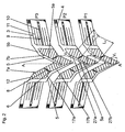
Fig. 2 eine Ansicht von drei unterschiedlich langen Pitches des Laufstreifenprofils ausFig. 1 .
-
Fig. 1 a plan view of a portion of the settlement of a tread pattern of a pneumatic vehicle tire with an embodiment of the invention and -
Fig. 2 a view of three different lengths pitches of the tread patternFig. 1 ,
Der in der Figur dargestellte Laufstreifen ist für einen Fahrzeugluftreifen für Personenkraftwagen vorgesehen und für einen Einsatz unter winterlichen Fahrbedingungen besonders geeignet. Mit A-A ist der Reifenäquator, mit B die Breite des Boden berührenden Teils des Laufstreifen (unter Nenndruck und Nennlast gemäß E.T.R.T.O Standards) bezeichnet. Der Laufstreifen weist ein laufrichtungsgebunden ausgeführtes Laufstreifenprofil mit in den beiden Laufstreifenhälften übereinstimmend ausgeführten Profilstrukturen auf, wobei die in der einen Laufstreifenhälfte vorgesehenen Profilstrukturen gegenüber jenen, die in der anderen Laufstreifenhälfte vorgesehen sind, in Umfangsrichtung geringfügig versetzt sind. Die konstruktive Ausgestaltung der Profilstrukturen zur Erzielung des Versatzes wird weiter unten anhand der
Das Laufstreifenprofil weist einen zentralen Profilbereich Z auf, auf dessen Ausgestaltung noch eingegangen wird und welcher zwischen 45 % und 55 % der Laufstreifenbreite B einnimmt. Der zentrale Bereich Z ist jeweils durch eine breite, in Umfangsrichtung umlaufende Umfangsrille 1 von je einer Schulterblockreihe 2 getrennt. Die Profilblöcke 3 in jeder Schulterblockreihe 2 sind in Umfangsrichtung voneinander durch Quernuten 4 getrennt, deren Breite zu den Laufstreifenrändern größer wird, welche ferner bei der gezeigten Ausführungsform gerade verlaufen und mit der Umfangsrichtung einen Winkel α einschließen, welcher insbesondere zwischen 65° und 85° gewählt wird, wobei in Folge der laufrichtungsgebundenen Ausführung des Laufstreifens die Quernuten 4 in der einen Schulterblockreihe 2 gegenüber den Quernuten 4 in der zweiten Schulterblockreihe 2 gegensinnig geneigt sind. Die Neigung ist ferner derart, dass die laufstreifeninnenseitig gelegenen Enden der Quernuten 4 beim Abrollen des Reifens zuerst in die Kontaktfläche mit dem Untergrund einlaufen. Im zentralen Bereich Z des Laufstreifens, sind als Hauptrillen Diagonalrillen 5 vorgesehen. Jede Diagonalrille 5 verläuft jenseits der jeweiligen Umfangsrille 1 etwa in Verlängerung einer Quernut 4 aus einer Schulterblockreihe 2 in Richtung Reifenäquator A-A, und geringfügig über den Reifenäquator A-A hinaus. Die in der einen Laufstreifenhälfte verlaufenden Diagonalrillen 5 sind daher gegenüber jenen, die in der anderen Laufstreifenhälfte verlaufen, analog zu den Quernuten 4 gegensinnig geneigt, sodass sich insgesamt eine gepfeilte Anordnung der Querrillen 4 und der Diagonalrillen 5 ergibt.The tread profile has a central profile region Z, will be discussed on the configuration and which occupies between 45% and 55% of the tread width B. The central region Z is in each case separated by a wide peripheral circumferential groove 1 of one
Jede Diagonalrille 5 weist zwei unter einem stumpfen Winkel γ zueinander verlaufende Rillenabschnitte 5a, 5b auf, wobei γ in der Größenordnung von 140° bis 160° beträgt. Die an die Umfangsrillen 1 anschließenden Rillenabschnitte 5a verlaufen unter einem Winkel β1 zur Umfangsrichtung, welcher zwischen 45° und 65° beträgt, die geringfügig über den Reifenäquator A-A verlaufenden Rillenabschnitte 5b schließen einen spitzen Winkel β2, welcher kleiner ist als β1 und in der Größenordnung von 20° bis 40° beträgt, mit der Umfangsrichtung bzw. dem Reifenäquator A-A ein. An ihren laufstreifeninnenseitigen Enden weisen die Diagonalrillen 5 ihre geringste Breite auf, wobei ihre Breite von diesen Enden ausgehend bis zur jeweiligen Umfangsrille 1 kontinuierlich größer wird. Zusätzliche Rillen 6 gliedern den zentralen Bereich in Profilblöcke 7a und profilblockartige Profilelemente 7b. Die zusätzlichen Rillen 6 verbinden jeweils zwei einander benachbart verlaufende Diagonalrillen 5 und verlaufen jeweils vom vorspringenden Knick einer Diagonalrille 5 zum Rillenabschnitt 5b der benachbarten Diagonalrille 5 unter einem Winkel δ von 20° bis 40° und gegensinnig zu den Diagonalrillen 5. Die Rillen 6 sind schmäler als die Diagonalrillen 5, ihre Tiefe ist geringer als die Tiefe der Umfangsrillen 1 bzw. der Diagonalrillen 5. Am Rillengrund der Rillen 6 kann ein schmaler Einschnitt 8 vorgesehen sein, welcher in einer Breite von 0,4 mm bis 1,0 mm ausgeführt ist und bis auf die vorgesehene Profiltiefe - dies ist die Tiefe der Umfangsrillen 1 - reichen kann.Each
Die schulterseitig angeordneten Profilblöcke 3 sind in ihrem mittleren Bereich durch in konstanter Breite ausgeführte zusätzliche Querrillen 9 zweigeteilt, welche parallel zu den Quernuten 4 verlaufen und in die Umfangrille 1 einmünden. Auch die zusätzlichen Querrillen 9 weisen eine geringere Tiefe auf als die Umfangsrillen 1 und können mittig mit einem schmalen, etwa 0,4 mm bis 0,6 mm breiten Einschnitt 10 versehen sein, welcher sich jeweils bevorzugt über die gesamte Länge der Querrille 9 erstreckt und eine Tiefe von 1 mm bis 3 mm aufweist.The shoulder-side arranged
Sämtliche Profilpositive sind jeweils mit einer Anzahl von Einschnitten 11, 12 versehen, deren Breite zwischen 0,4 mm und 0,6 mm beträgt. In den Schulterblöcken 3 ist zumindest je ein Einschnitt 11 im Schulterblockteil zwischen der zusätzlichen Querrille 9 und der Quernut 4 vorgesehen, je nach Umfangslänge der Schulterblöcke 3 sind in den Schulterblockteilen auch zwei Einschnitte 11 vorgesehen. Die Einschnitte 11 erstrecken sich parallel zu den Quernuten 4 und weisen zwei in Draufsicht gerade verlaufende Einschnittabschnitte 11a und eine zwischen diesen verlaufenden mittleren Abschnitt 11b auf, welcher in Draufsicht eine Wellen- bzw. Zickzackform aufweist. Die wellenförmigen Abschnitte 11b tragen dazu bei, dass sich die Profilblöcke 3 in den Schulterblockreihen 2 bei Querkräften versteifen können.All profile positives are each provided with a number of
Im zentralen Bereich Z des Laufstreifens sind in Draufsicht gerade verlaufende Einschnitte 12 angeordnet. Die Einschnitte 12 können in Laufstreifenquerrichtung verlaufen oder es sind die auf der eine Seite des Reifenäquators A-A verlaufenden Einschnitte 12 gegenüber jenen, die an der anderen Seite des Reifenäquators A-A verlaufen, gegensinnig geneigt und auch jeweils gegensinnig zum Verlauf der dort angeordneten Diagonalrillen 5 geneigt. Der Neigungswinkel ϕ der Einschnitte 12 zur Umfangsrichtung (Reifenäquator A-A) beträgt zwischen 90° und 120°. Beim Reifenäquator A-A verlaufen einige Einschnitte 12 aus der einen Laufstreifenhälfte geringfügig über den Reifenäquator A-A hinaus und enden bei der nächsten Diagonalrille 5. Pro Profilblock 7a bzw. blockartigem Profilelement 7b sind zwischen 5 und 7 Einschnitte 12 vorgesehen, deren gegenseitiger Abstand etwa 5 mm bis 6,5 mm beträgt. Die geraden und zumindest im Wesentlichen in Laufstreifenrichtung verlaufenden Einschnitte 12 im zentralen Bereich Z des Laufstreifens unterstützen eine möglichst optimale Kraftübertragung auf Schnee. Beim Wirken von Umfangskräften können sich diese geraden Einschnitte 12 sehr gut öffnen und mit Schnee befüllen, sodass die derart verstärkte Schnee-Schnee-Reibung das gesamte Griffpotential des Laufstreifens bzw. Reifens auf schneeigem Untergrund deutlich erhöht.In the central region Z of the tread
Die Einschnitte 11, 12 können ferner in bekannter Weise Abschnitte mit unterschiedlichen Tiefen aufweisen.The
Zur Erzielung eines unauffälligen und möglichst geringen Abrollgeräusches ist das Laufstreifenprofil geräuschoptimiert ausgelegt. Dazu ist das Laufstreifenprofil in sogenannte Pitches gegliedert, bei der dargestellten Ausführungsvariante sind drei Pitches P1, P2 und P3 mit unterschiedlichen Umfangslängen vorgesehen. Das Pitch P1 weist die geringste Umfangslänge auf, das Pitch P3 die größte Umfangslänge, P2 weist eine Umfangslänge auf, die zwischen der längsten und der kürzesten Umfangslänge liegt. Wie bekannt werden die Pitches P1, P2, P3 über den Reifenumfang gemäß einer sogenannten Pitchfolge angeordnet, wobei die Gesamtanzahl der Pitches über den Reifenumfang in einem PKW-Winterreifen in der Größenordnung von 65 bis 90 beträgt. In einer Pitchfolge können an manchen Stellen des Reifenumfangs zwei oder mehr Pitches gleicher Länge hintereinander angeordnet sein.To achieve an inconspicuous and minimized rolling noise, the tread pattern is designed noise optimized. For this purpose, the tread pattern is divided into so-called pitches, in the illustrated embodiment, three pitches P1, P2 and P3 are provided with different circumferential lengths. The pitch P1 has the smallest circumferential length, the pitch P3 the largest circumferential length, P2 has a circumferential length which lies between the longest and the shortest circumferential length. As is known, the pitches P1, P2, P3 over the tire circumference according to a so-called Pitch order, wherein the total number of pitches over the tire circumference in a car winter tire is on the order of 65 to 90. In a pitch sequence, two or more pitches of the same length can be arranged in succession at some points of the tire circumference.
Zu jedem Pitch P1, P2, P3 gehört jeweils ein Profilblock 3 aus jeder Schulterblockreihe 2 mitsamt der, bezogen auf die Abrollrichtung des Reifens bei Vorwärtsfahrt, an die auslaufende Profilblockkante 3a anschließenden Quernut 4. Die Umfangserstreckung der Schulterblöcke 3 und der Quernuten 4 ist in einem Pitch P1 mit der kleinsten Umfangslänge am geringsten, in einem Pitch P3 mit der größten Umfangslänge am größten. Je nach Umfangslänge sind daher auch in den Profilblöcken 3 zwei, drei oder vier der bereits beschriebenen Einschnitte 11 vorhanden. Aus dem zentralen Bereich Z gehören zu jedem Pitch P1, P2, P3 jeweils zwei Diagonalrillen 5 sowie zwei Profilblöcke 7a und zwei blockartige Profilpositive 7b. Die Diagonalrille 5 in der einen Laufstreifenhälfte befindet sich , bezogen auf die Abrollrichtung, an den auslaufenden Kanten 17a, 17b des Profilblockes 7a und des blockartigen Profilpositivs 7b. In der zweiten Laufstreifenhälfte befindet sich die zu jedem Pitch P1, P2 und P3 gehörenden zweiten Diagonalrillen 5 an den einlaufenden Kanten 27a, 27b des Profilblocks 7a und des blockartigen Profilpositivs 7b. Die Diagonalrillen 5 in jedem Pitch P1, P2, P3 sind jeweils gleich ausgeführt und in Umfangsrichtung gegeneinander versetzt, wobei für den jeweiligen Versatz V1, V2, V3, welcher entlang des Reifenäquators ermittelt wird, gilt, dass V1 < V2 < V3. Auch im zentralen Bereich Z des Laufstreifens ist die Breite der Diagonalrillen 5 auf die Umfangserstreckung der Profilpositive - Profilblöcke 7a und blockartige Profilpositive 7b - abgestimmt, sodass im Pitch P1 die geringste Umfangserstreckung bzw. Diagonalrillenbreite vorliegt und im Pitch 3 die breitesten Diagonalrillen 5 und die größte Umfangserstreckung der Profilblöcke 7a und der blockartigen Profilpositive 7b. Die Winkel α, β1, β2, δ und γ sind in sämtlichen Pitches P1, P2, P3 gleich groß, und die Rillenabschnitte 5a und 5b weisen in sämtlichen Pitches P1, P2, P3 im Wesentlichen übereinstimmende Längen L1, L2 auf, wobei die Längen L1, L2 jeweils an den einlaufenden Kanten 27a, 27b ermittelt werden.For each pitch P1, P2, P3 belongs in each case a
Das Laufstreifenprofil gemäß der Erfindung ist daher im Wesentlichen ein bezüglich des Reifenäquators A-A "spiegelsymmetrisch versetztes" Laufstreifenprofil mit einem, bedingt durch die Anordnung der Diagonalrillen 5, sehr gutem Wasserdrainagevermögen. Durch die besondere Anordnung der Diagonalrillen 5 in jedem Pitch P1, P2, P3, die im Wesentlichen übereinstimmenden Längen L1, L2 sowie die übereinstimmenden Winkel α, β1, β2, δ und γ sind in jedem Pitch P1, P2, P3 die auf der einen Seite des Reifenäquators A-A befindlichen Profilpositivflächen gleich groß zu jenen, die sich auf der anderen Seite des Reifenäquators befinden. Über den gesamten Reifenumfang betrachtet ist daher in der linken Laufstreifenhälfte gleich viel "Profilpositiv" vorhanden wie in der rechten Laufstreifenhälfte, unabhängig davon, ob die Anzahl von Pitches über den Laufstreifenumfang gerade oder ungerade ist. Dies ist mit dem Vorteil verbunden, dass sich beim Aufpumpen des Reifens der radial innerhalb des Laufstreifens befindliche Gürtelverband gleichmäßig dehnt, wodurch sich eine gleichmäßige torusförmige Außenfläche des Reifens im Laufstreifenbereich einstellt.The tread pattern according to the invention is therefore essentially a relative to the tire equator AA "mirror-symmetrically offset" tread pattern with a, due to the arrangement of the
Die Erfindung ist auf das dargestellte Laufstreifenprofil nicht eingeschränkt. In erfindungsgemäß ausgeführten Profilen können lediglich zwei Pitches oder mehr als drei Pitches mit unterschiedlichen Umfangslängen vorgesehen sein.The invention is not limited to the illustrated tread pattern. In profiles according to the invention, only two pitches or more than three pitches with different circumferential lengths can be provided.
- 11
- ................ Umfangsrille................ circumferential groove
- 22
- ................ Schulterblockreihe................ shoulder block row
- 33
- ................ Profilblock................ profile block
- 3a3a
- .................umlaufende Kante................. circumferential edge
- 44
- ............... Quernuten............... cross grooves
- 55
- ................ Diagonalrille................ Diagonal groove
- 5a5a
- .................Rillenabschnitt................. groove portion
- 5b5b
- .................Rillenabschnitt................. groove portion
- 66
- ................ zusätzliche Rille................ additional groove
- 7a7a
- .................Profilblock................. tread block
- 7b7b
- .................blockartiges Profilpositiv................. Block-like profile positive
- 88th
- ...................Einschnitt...................Incision
- 99
- ...................zusätzliche Querrille................... additional transverse groove
- 1010
- ............... Einschnitt............... incision
- 1111
- ............... Einschnitt............... incision
- 11a11a
- ............... Einschnittabschnitt............... incision section
- 11b11b
- ...............Einschnittabschnitt............... cut portion
- 1212
- ............... Einschnitt............... incision
- 17a17a
- ............... auslaufende Kante............... leaking edge
- 17b17b
- ............... auslaufende Kante............... leaking edge
- 27a27a
- ...............einlaufende Kante............... incoming edge
- 27b27b
- ...............einlaufende Kante............... incoming edge
- αα
- ................... Winkel................... Angle
- β1 β 1
- .................Winkel.................Angle
- β2 β 2
- ................. Winkel................. Angle
- γγ
- ................... Winkel................... Angle
- δδ
- ................... Winkel................... Angle
- ϕφ
- .................. Winkel.................. Angle
- A-AA-A
- .............. Reifenäquator.............. Tire equator
- BB
- ..................Breite..................Width
- L1L1
- ................Länge................Length
- L2L2
- ................Länge................Length
- ZZ
- ..................zentraler Bereich.................. central area
- P1P1
- .................Pitch................. pitch
- P2P2
- .................Pitch................. pitch
- P3P3
- .................Pitch................. pitch
- V1 V 1
- ................. Versatz................. Offset
- V2 V 2
- ................. Versatz................. Offset
- V3 V 3
- ................. Versatz................. Offset
Claims (3)
- Pneumatic vehicle tyre of radial design, in particular for use in winter driving conditions, having a tread strip which has shoulder-side profile block rows with shoulder blocks which are separated from one another by transverse grooves (4), the shoulder-side profile block rows being separated in each case by a circumferential groove (1) which runs around in the circumferential direction from a central tread strip region which is free of circumferential grooves, in which tread strip region profile blocks/profile positives (7a, 7b) are formed by diagonal grooves (5) which, together with the transverse grooves (4) from the shoulder-side profile block rows, are arranged substantially in a V-shape over the tread strip width, the diagonal grooves (5) in one tread strip half being offset in the circumferential direction with respect to those in the other tread strip half, opening with their one end into the circumferential groove (1) of the respective tread strip half and in each case running slightly beyond the equator of the tyre (A-A) into the respective other tread strip half, and in each case one shoulder block from each shoulder block row forming in each case one pitch (P1, P2, P3) with in each case one adjacent transverse groove (4), with two diagonal grooves (5) (in each case one from each tread strip half) and including the profile positives (7a, 7b) which run adjacently with respect to them, the pitches (P1, P2, P3) being provided in at least two different circumferential lengths and being delimited by two pitch boundaries which are assigned to the tread strip transverse direction and run over the tread strip width, characterized in that, in every pitch (P1, P2, P3), that diagonal groove (5) within the pitch (P1, P2, P3) which runs in one tread strip half runs along one pitch boundary and that diagonal groove (5) within the pitch (P1, P2, P3) which runs in the other tread strip half runs along the other pitch boundary, and in that the two diagonal grooves (5) which belong to a pitch (P1, P2, P3) have coinciding widths and run at equally large angles with respect to the equator of the tyre (A-A).
- Pneumatic vehicle tyre according to Claim 1, characterized in that the width of the diagonal grooves (5) becomes continuously larger to the outside.
- Pneumatic vehicle tyre according to Claim 1, characterized in that the diagonal grooves (5) have two groove sections (5a, 5b) which run at an obtuse angle with respect to one another, the section (5a) which runs slightly beyond the equator of the tyre (A-A) running at an angle (β2) of from 20° to 40° with respect to the equator of the tyre (A-A).
Applications Claiming Priority (1)
| Application Number | Priority Date | Filing Date | Title |
|---|---|---|---|
| DE201010061086 DE102010061086A1 (en) | 2010-12-07 | 2010-12-07 | Vehicle tires |
Publications (2)
| Publication Number | Publication Date |
|---|---|
| EP2463123A1 EP2463123A1 (en) | 2012-06-13 |
| EP2463123B1 true EP2463123B1 (en) | 2014-04-23 |
Family
ID=45440073
Family Applications (1)
| Application Number | Title | Priority Date | Filing Date |
|---|---|---|---|
| EP20110187420 Active EP2463123B1 (en) | 2010-12-07 | 2011-11-02 | Pneumatic tyre for a vehicle |
Country Status (2)
| Country | Link |
|---|---|
| EP (1) | EP2463123B1 (en) |
| DE (1) | DE102010061086A1 (en) |
Families Citing this family (9)
| Publication number | Priority date | Publication date | Assignee | Title |
|---|---|---|---|---|
| JP5578296B1 (en) * | 2012-12-11 | 2014-08-27 | 横浜ゴム株式会社 | Pneumatic tire |
| CN107972414B (en) * | 2013-01-28 | 2020-03-10 | 倍耐力轮胎股份公司 | Tyre for vehicle wheels |
| DE102014213266A1 (en) | 2014-07-09 | 2016-01-14 | Continental Reifen Deutschland Gmbh | Vehicle tires |
| EP3303008B1 (en) * | 2015-05-27 | 2019-12-18 | Pirelli Tyre S.p.A. | A tyre for vehicle wheels |
| DE102016217970A1 (en) * | 2016-09-20 | 2018-03-22 | Continental Reifen Deutschland Gmbh | Vehicle tires |
| DE102017211130A1 (en) * | 2017-06-30 | 2019-01-03 | Continental Reifen Deutschland Gmbh | Vehicle tires |
| WO2020012279A1 (en) * | 2018-07-13 | 2020-01-16 | Pirelli Tyre S.P.A. | Tyre for vehicle wheels |
| IT201800009473A1 (en) * | 2018-10-16 | 2020-04-16 | Bridgestone Europe Nv Sa | OUTSOLE FOR WINTER TIRE AND WINTER TIRE |
| FR3099084B1 (en) * | 2019-07-26 | 2021-06-25 | Michelin & Cie | Tire with a tread |
Family Cites Families (3)
| Publication number | Priority date | Publication date | Assignee | Title |
|---|---|---|---|---|
| DE4300695A1 (en) * | 1993-01-13 | 1994-07-14 | Sp Reifenwerke Gmbh | Tread for pneumatic vehicle tires |
| DE50304375D1 (en) * | 2003-11-21 | 2006-09-07 | Continental Ag | Tread pattern for a pneumatic vehicle tire |
| DE102007044435A1 (en) * | 2007-09-18 | 2009-03-19 | Continental Aktiengesellschaft | Vehicle tires |
-
2010
- 2010-12-07 DE DE201010061086 patent/DE102010061086A1/en not_active Withdrawn
-
2011
- 2011-11-02 EP EP20110187420 patent/EP2463123B1/en active Active
Also Published As
| Publication number | Publication date |
|---|---|
| EP2463123A1 (en) | 2012-06-13 |
| DE102010061086A1 (en) | 2012-06-14 |
Similar Documents
| Publication | Publication Date | Title |
|---|---|---|
| EP2463123B1 (en) | Pneumatic tyre for a vehicle | |
| EP2646263B1 (en) | Vehicle pneumatic tire | |
| EP2965925B1 (en) | Pneumatic tyres for a vehicle | |
| EP1795372B1 (en) | Tire tread profile | |
| DE102007061148A1 (en) | Vehicle tires | |
| EP3645317B1 (en) | Pneumatic vehicle tires | |
| EP1529659B1 (en) | Pneumatic vehicle tyre | |
| EP2460672B1 (en) | Pneumatic tyre for a vehicle | |
| EP3383669B1 (en) | Pneumatic vehicle tires | |
| EP2138327B1 (en) | Tire tread for pneumatic tire | |
| EP3750723B1 (en) | Pneumatic tyre | |
| EP3450213A1 (en) | Pneumatic tyre for a vehicle | |
| EP2138329B1 (en) | Tire tread for pneumatic tire | |
| EP3519208B1 (en) | Pneumatic vehicle tyres | |
| EP2138328B1 (en) | Pneumatic tyres for a vehicle | |
| EP3230087B1 (en) | A pneumatic tire for a vehicle | |
| EP3256335B1 (en) | Pneumatic tyre for a vehicle | |
| EP3917791B1 (en) | Pneumatic tyre | |
| EP1234692B1 (en) | Vehicle tyre whose tread land portions comprise transverse sipes. | |
| EP3753753B1 (en) | Pneumatic tyre | |
| EP2123485B1 (en) | Pneumatic tyres for a vehicle | |
| EP2090443A1 (en) | Pneumatic tire | |
| EP1529661B1 (en) | Pneumatic tires for vehicles | |
| DE102019210431A1 (en) | Pneumatic vehicle tires | |
| EP1974956A1 (en) | Pneumatic tyres for a vehicle |
Legal Events
| Date | Code | Title | Description |
|---|---|---|---|
| PUAI | Public reference made under article 153(3) epc to a published international application that has entered the european phase |
Free format text: ORIGINAL CODE: 0009012 |
|
| AK | Designated contracting states |
Kind code of ref document: A1 Designated state(s): AL AT BE BG CH CY CZ DE DK EE ES FI FR GB GR HR HU IE IS IT LI LT LU LV MC MK MT NL NO PL PT RO RS SE SI SK SM TR |
|
| AX | Request for extension of the european patent |
Extension state: BA ME |
|
| 17P | Request for examination filed |
Effective date: 20121213 |
|
| GRAP | Despatch of communication of intention to grant a patent |
Free format text: ORIGINAL CODE: EPIDOSNIGR1 |
|
| INTG | Intention to grant announced |
Effective date: 20140103 |
|
| GRAS | Grant fee paid |
Free format text: ORIGINAL CODE: EPIDOSNIGR3 |
|
| GRAA | (expected) grant |
Free format text: ORIGINAL CODE: 0009210 |
|
| AK | Designated contracting states |
Kind code of ref document: B1 Designated state(s): AL AT BE BG CH CY CZ DE DK EE ES FI FR GB GR HR HU IE IS IT LI LT LU LV MC MK MT NL NO PL PT RO RS SE SI SK SM TR |
|
| REG | Reference to a national code |
Ref country code: GB Ref legal event code: FG4D Free format text: NOT ENGLISH |
|
| REG | Reference to a national code |
Ref country code: CH Ref legal event code: EP |
|
| REG | Reference to a national code |
Ref country code: AT Ref legal event code: REF Ref document number: 663585 Country of ref document: AT Kind code of ref document: T Effective date: 20140515 |
|
| REG | Reference to a national code |
Ref country code: IE Ref legal event code: FG4D Free format text: LANGUAGE OF EP DOCUMENT: GERMAN |
|
| REG | Reference to a national code |
Ref country code: DE Ref legal event code: R096 Ref document number: 502011002809 Country of ref document: DE Effective date: 20140528 |
|
| REG | Reference to a national code |
Ref country code: NL Ref legal event code: VDEP Effective date: 20140423 |
|
| REG | Reference to a national code |
Ref country code: LT Ref legal event code: MG4D |
|
| PG25 | Lapsed in a contracting state [announced via postgrant information from national office to epo] |
Ref country code: LT Free format text: LAPSE BECAUSE OF FAILURE TO SUBMIT A TRANSLATION OF THE DESCRIPTION OR TO PAY THE FEE WITHIN THE PRESCRIBED TIME-LIMIT Effective date: 20140423 Ref country code: FI Free format text: LAPSE BECAUSE OF FAILURE TO SUBMIT A TRANSLATION OF THE DESCRIPTION OR TO PAY THE FEE WITHIN THE PRESCRIBED TIME-LIMIT Effective date: 20140423 Ref country code: GR Free format text: LAPSE BECAUSE OF FAILURE TO SUBMIT A TRANSLATION OF THE DESCRIPTION OR TO PAY THE FEE WITHIN THE PRESCRIBED TIME-LIMIT Effective date: 20140724 Ref country code: CY Free format text: LAPSE BECAUSE OF FAILURE TO SUBMIT A TRANSLATION OF THE DESCRIPTION OR TO PAY THE FEE WITHIN THE PRESCRIBED TIME-LIMIT Effective date: 20140423 Ref country code: IS Free format text: LAPSE BECAUSE OF FAILURE TO SUBMIT A TRANSLATION OF THE DESCRIPTION OR TO PAY THE FEE WITHIN THE PRESCRIBED TIME-LIMIT Effective date: 20140823 Ref country code: BG Free format text: LAPSE BECAUSE OF FAILURE TO SUBMIT A TRANSLATION OF THE DESCRIPTION OR TO PAY THE FEE WITHIN THE PRESCRIBED TIME-LIMIT Effective date: 20140723 Ref country code: NO Free format text: LAPSE BECAUSE OF FAILURE TO SUBMIT A TRANSLATION OF THE DESCRIPTION OR TO PAY THE FEE WITHIN THE PRESCRIBED TIME-LIMIT Effective date: 20140723 Ref country code: NL Free format text: LAPSE BECAUSE OF FAILURE TO SUBMIT A TRANSLATION OF THE DESCRIPTION OR TO PAY THE FEE WITHIN THE PRESCRIBED TIME-LIMIT Effective date: 20140423 |
|
| PG25 | Lapsed in a contracting state [announced via postgrant information from national office to epo] |
Ref country code: LV Free format text: LAPSE BECAUSE OF FAILURE TO SUBMIT A TRANSLATION OF THE DESCRIPTION OR TO PAY THE FEE WITHIN THE PRESCRIBED TIME-LIMIT Effective date: 20140423 Ref country code: RS Free format text: LAPSE BECAUSE OF FAILURE TO SUBMIT A TRANSLATION OF THE DESCRIPTION OR TO PAY THE FEE WITHIN THE PRESCRIBED TIME-LIMIT Effective date: 20140423 Ref country code: SE Free format text: LAPSE BECAUSE OF FAILURE TO SUBMIT A TRANSLATION OF THE DESCRIPTION OR TO PAY THE FEE WITHIN THE PRESCRIBED TIME-LIMIT Effective date: 20140423 Ref country code: HR Free format text: LAPSE BECAUSE OF FAILURE TO SUBMIT A TRANSLATION OF THE DESCRIPTION OR TO PAY THE FEE WITHIN THE PRESCRIBED TIME-LIMIT Effective date: 20140423 Ref country code: ES Free format text: LAPSE BECAUSE OF FAILURE TO SUBMIT A TRANSLATION OF THE DESCRIPTION OR TO PAY THE FEE WITHIN THE PRESCRIBED TIME-LIMIT Effective date: 20140423 Ref country code: PL Free format text: LAPSE BECAUSE OF FAILURE TO SUBMIT A TRANSLATION OF THE DESCRIPTION OR TO PAY THE FEE WITHIN THE PRESCRIBED TIME-LIMIT Effective date: 20140423 |
|
| PG25 | Lapsed in a contracting state [announced via postgrant information from national office to epo] |
Ref country code: PT Free format text: LAPSE BECAUSE OF FAILURE TO SUBMIT A TRANSLATION OF THE DESCRIPTION OR TO PAY THE FEE WITHIN THE PRESCRIBED TIME-LIMIT Effective date: 20140825 |
|
| REG | Reference to a national code |
Ref country code: DE Ref legal event code: R097 Ref document number: 502011002809 Country of ref document: DE |
|
| PG25 | Lapsed in a contracting state [announced via postgrant information from national office to epo] |
Ref country code: CZ Free format text: LAPSE BECAUSE OF FAILURE TO SUBMIT A TRANSLATION OF THE DESCRIPTION OR TO PAY THE FEE WITHIN THE PRESCRIBED TIME-LIMIT Effective date: 20140423 Ref country code: SK Free format text: LAPSE BECAUSE OF FAILURE TO SUBMIT A TRANSLATION OF THE DESCRIPTION OR TO PAY THE FEE WITHIN THE PRESCRIBED TIME-LIMIT Effective date: 20140423 Ref country code: DK Free format text: LAPSE BECAUSE OF FAILURE TO SUBMIT A TRANSLATION OF THE DESCRIPTION OR TO PAY THE FEE WITHIN THE PRESCRIBED TIME-LIMIT Effective date: 20140423 Ref country code: EE Free format text: LAPSE BECAUSE OF FAILURE TO SUBMIT A TRANSLATION OF THE DESCRIPTION OR TO PAY THE FEE WITHIN THE PRESCRIBED TIME-LIMIT Effective date: 20140423 Ref country code: RO Free format text: LAPSE BECAUSE OF FAILURE TO SUBMIT A TRANSLATION OF THE DESCRIPTION OR TO PAY THE FEE WITHIN THE PRESCRIBED TIME-LIMIT Effective date: 20140423 |
|
| PLBE | No opposition filed within time limit |
Free format text: ORIGINAL CODE: 0009261 |
|
| STAA | Information on the status of an ep patent application or granted ep patent |
Free format text: STATUS: NO OPPOSITION FILED WITHIN TIME LIMIT |
|
| PG25 | Lapsed in a contracting state [announced via postgrant information from national office to epo] |
Ref country code: IT Free format text: LAPSE BECAUSE OF FAILURE TO SUBMIT A TRANSLATION OF THE DESCRIPTION OR TO PAY THE FEE WITHIN THE PRESCRIBED TIME-LIMIT Effective date: 20140423 |
|
| 26N | No opposition filed |
Effective date: 20150126 |
|
| REG | Reference to a national code |
Ref country code: DE Ref legal event code: R097 Ref document number: 502011002809 Country of ref document: DE Effective date: 20150126 |
|
| PG25 | Lapsed in a contracting state [announced via postgrant information from national office to epo] |
Ref country code: BE Free format text: LAPSE BECAUSE OF NON-PAYMENT OF DUE FEES Effective date: 20141130 Ref country code: LU Free format text: LAPSE BECAUSE OF FAILURE TO SUBMIT A TRANSLATION OF THE DESCRIPTION OR TO PAY THE FEE WITHIN THE PRESCRIBED TIME-LIMIT Effective date: 20141102 Ref country code: MC Free format text: LAPSE BECAUSE OF FAILURE TO SUBMIT A TRANSLATION OF THE DESCRIPTION OR TO PAY THE FEE WITHIN THE PRESCRIBED TIME-LIMIT Effective date: 20140423 |
|
| PG25 | Lapsed in a contracting state [announced via postgrant information from national office to epo] |
Ref country code: SI Free format text: LAPSE BECAUSE OF FAILURE TO SUBMIT A TRANSLATION OF THE DESCRIPTION OR TO PAY THE FEE WITHIN THE PRESCRIBED TIME-LIMIT Effective date: 20140423 |
|
| REG | Reference to a national code |
Ref country code: IE Ref legal event code: MM4A |
|
| REG | Reference to a national code |
Ref country code: FR Ref legal event code: ST Effective date: 20150731 |
|
| PG25 | Lapsed in a contracting state [announced via postgrant information from national office to epo] |
Ref country code: IE Free format text: LAPSE BECAUSE OF NON-PAYMENT OF DUE FEES Effective date: 20141102 |
|
| PG25 | Lapsed in a contracting state [announced via postgrant information from national office to epo] |
Ref country code: FR Free format text: LAPSE BECAUSE OF NON-PAYMENT OF DUE FEES Effective date: 20141201 |
|
| PG25 | Lapsed in a contracting state [announced via postgrant information from national office to epo] |
Ref country code: SM Free format text: LAPSE BECAUSE OF FAILURE TO SUBMIT A TRANSLATION OF THE DESCRIPTION OR TO PAY THE FEE WITHIN THE PRESCRIBED TIME-LIMIT Effective date: 20140423 |
|
| GBPC | Gb: european patent ceased through non-payment of renewal fee |
Effective date: 20151102 |
|
| PG25 | Lapsed in a contracting state [announced via postgrant information from national office to epo] |
Ref country code: MT Free format text: LAPSE BECAUSE OF FAILURE TO SUBMIT A TRANSLATION OF THE DESCRIPTION OR TO PAY THE FEE WITHIN THE PRESCRIBED TIME-LIMIT Effective date: 20140423 Ref country code: TR Free format text: LAPSE BECAUSE OF FAILURE TO SUBMIT A TRANSLATION OF THE DESCRIPTION OR TO PAY THE FEE WITHIN THE PRESCRIBED TIME-LIMIT Effective date: 20140423 Ref country code: HU Free format text: LAPSE BECAUSE OF FAILURE TO SUBMIT A TRANSLATION OF THE DESCRIPTION OR TO PAY THE FEE WITHIN THE PRESCRIBED TIME-LIMIT; INVALID AB INITIO Effective date: 20111102 |
|
| PG25 | Lapsed in a contracting state [announced via postgrant information from national office to epo] |
Ref country code: GB Free format text: LAPSE BECAUSE OF NON-PAYMENT OF DUE FEES Effective date: 20151102 |
|
| PG25 | Lapsed in a contracting state [announced via postgrant information from national office to epo] |
Ref country code: MK Free format text: LAPSE BECAUSE OF FAILURE TO SUBMIT A TRANSLATION OF THE DESCRIPTION OR TO PAY THE FEE WITHIN THE PRESCRIBED TIME-LIMIT Effective date: 20140423 |
|
| PG25 | Lapsed in a contracting state [announced via postgrant information from national office to epo] |
Ref country code: AL Free format text: LAPSE BECAUSE OF FAILURE TO SUBMIT A TRANSLATION OF THE DESCRIPTION OR TO PAY THE FEE WITHIN THE PRESCRIBED TIME-LIMIT Effective date: 20140423 |
|
| PGFP | Annual fee paid to national office [announced via postgrant information from national office to epo] |
Ref country code: AT Payment date: 20181121 Year of fee payment: 8 |
|
| PGFP | Annual fee paid to national office [announced via postgrant information from national office to epo] |
Ref country code: CH Payment date: 20181120 Year of fee payment: 8 |
|
| REG | Reference to a national code |
Ref country code: CH Ref legal event code: PL |
|
| PG25 | Lapsed in a contracting state [announced via postgrant information from national office to epo] |
Ref country code: LI Free format text: LAPSE BECAUSE OF NON-PAYMENT OF DUE FEES Effective date: 20191130 Ref country code: CH Free format text: LAPSE BECAUSE OF NON-PAYMENT OF DUE FEES Effective date: 20191130 |
|
| REG | Reference to a national code |
Ref country code: AT Ref legal event code: MM01 Ref document number: 663585 Country of ref document: AT Kind code of ref document: T Effective date: 20191102 |
|
| PG25 | Lapsed in a contracting state [announced via postgrant information from national office to epo] |
Ref country code: AT Free format text: LAPSE BECAUSE OF NON-PAYMENT OF DUE FEES Effective date: 20191102 |
|
| PGFP | Annual fee paid to national office [announced via postgrant information from national office to epo] |
Ref country code: DE Payment date: 20231130 Year of fee payment: 13 |
|
| REG | Reference to a national code |
Ref country code: DE Ref legal event code: R081 Ref document number: 502011002809 Country of ref document: DE Owner name: CONTINENTAL REIFEN DEUTSCHLAND GMBH, DE Free format text: FORMER OWNER: CONTINENTAL REIFEN DEUTSCHLAND GMBH, 30165 HANNOVER, DE |