EP2463049A1 - Cutting machine - Google Patents
Cutting machine Download PDFInfo
- Publication number
- EP2463049A1 EP2463049A1 EP11190537A EP11190537A EP2463049A1 EP 2463049 A1 EP2463049 A1 EP 2463049A1 EP 11190537 A EP11190537 A EP 11190537A EP 11190537 A EP11190537 A EP 11190537A EP 2463049 A1 EP2463049 A1 EP 2463049A1
- Authority
- EP
- European Patent Office
- Prior art keywords
- housing
- blow passage
- rod
- cutting machine
- blow
- Prior art date
- Legal status (The legal status is an assumption and is not a legal conclusion. Google has not performed a legal analysis and makes no representation as to the accuracy of the status listed.)
- Granted
Links
Images


Classifications
-
- B—PERFORMING OPERATIONS; TRANSPORTING
- B23—MACHINE TOOLS; METAL-WORKING NOT OTHERWISE PROVIDED FOR
- B23D—PLANING; SLOTTING; SHEARING; BROACHING; SAWING; FILING; SCRAPING; LIKE OPERATIONS FOR WORKING METAL BY REMOVING MATERIAL, NOT OTHERWISE PROVIDED FOR
- B23D59/00—Accessories specially designed for sawing machines or sawing devices
- B23D59/006—Accessories specially designed for sawing machines or sawing devices for removing or collecting chips
- B23D59/0062—Accessories specially designed for sawing machines or sawing devices for removing or collecting chips by blowing
-
- B—PERFORMING OPERATIONS; TRANSPORTING
- B23—MACHINE TOOLS; METAL-WORKING NOT OTHERWISE PROVIDED FOR
- B23D—PLANING; SLOTTING; SHEARING; BROACHING; SAWING; FILING; SCRAPING; LIKE OPERATIONS FOR WORKING METAL BY REMOVING MATERIAL, NOT OTHERWISE PROVIDED FOR
- B23D49/00—Machines or devices for sawing with straight reciprocating saw blades, e.g. hacksaws
- B23D49/10—Hand-held or hand-operated sawing devices with straight saw blades
- B23D49/16—Hand-held or hand-operated sawing devices with straight saw blades actuated by electric or magnetic power or prime movers
- B23D49/162—Pad sawing devices
-
- B—PERFORMING OPERATIONS; TRANSPORTING
- B23—MACHINE TOOLS; METAL-WORKING NOT OTHERWISE PROVIDED FOR
- B23D—PLANING; SLOTTING; SHEARING; BROACHING; SAWING; FILING; SCRAPING; LIKE OPERATIONS FOR WORKING METAL BY REMOVING MATERIAL, NOT OTHERWISE PROVIDED FOR
- B23D59/00—Accessories specially designed for sawing machines or sawing devices
- B23D59/006—Accessories specially designed for sawing machines or sawing devices for removing or collecting chips
- B23D59/0064—Accessories specially designed for sawing machines or sawing devices for removing or collecting chips by suction
-
- B—PERFORMING OPERATIONS; TRANSPORTING
- B23—MACHINE TOOLS; METAL-WORKING NOT OTHERWISE PROVIDED FOR
- B23Q—DETAILS, COMPONENTS, OR ACCESSORIES FOR MACHINE TOOLS, e.g. ARRANGEMENTS FOR COPYING OR CONTROLLING; MACHINE TOOLS IN GENERAL CHARACTERISED BY THE CONSTRUCTION OF PARTICULAR DETAILS OR COMPONENTS; COMBINATIONS OR ASSOCIATIONS OF METAL-WORKING MACHINES, NOT DIRECTED TO A PARTICULAR RESULT
- B23Q11/00—Accessories fitted to machine tools for keeping tools or parts of the machine in good working condition or for cooling work; Safety devices specially combined with or arranged in, or specially adapted for use in connection with, machine tools
- B23Q11/12—Arrangements for cooling or lubricating parts of the machine
- B23Q11/126—Arrangements for cooling or lubricating parts of the machine for cooling only
- B23Q11/127—Arrangements for cooling or lubricating parts of the machine for cooling only for cooling motors or spindles
Definitions
- the present invention relates to a cutting machine in which a reciprocating rod driven by a motor projects downward at a forward portion of a housing that accommodates the motor and a cooling fan for cooling the motor, and a lower end of the rod is connected to a cutting blade to cut a workpiece.
- Japanese Patent No. 4248766B discloses a cutting machine which cuts a workpiece with a blade connected to a lower end of a reciprocating rod projecting downward at a forward portion of a housing, so as to prevent the scattering of chips generated from the workpiece being cut by the blade.
- an outlet of a nozzle from which air for cooling a motor blows on a front side of the blade opens rearward so that cooling air gently blows rearward from the front side of the blade.
- Such cooling air functions as an air curtain that forwardly covers a cutting place of the workpiece. In other words, the cooling air blocks the chips from scattering forwardly.
- an object of the present invention is to provide a cutting machine that can prevent the chips from entering a housing from a section where a rod connected to a blade projects from the housing.
- a cutting machine includes a housing, a motor and a cooling fan for cooling the motor that are accommodated in the housing, a reciprocating rod driven by the motor, projecting downward at a forward portion of the housing, a cutting blade for cutting a workpiece, being connected to a lower end of the rod, and a first blow passage formed in the housing. Cooling air generated by the cooling fan forwardly flows through the first blow passage in a direction intersecting the rod from a rear side relative to the rod.
- a pair of the first blow passages are provided in the housing, and the cooling air through the first blow passage flows leftward and rightward from the rear side of the rod.
- a second blow passage is formed in the housing and the cooling air flows through the second blow passage toward a cutting place of the workpiece being cut by the cutting blade.
- the first blow passage and the second blow passage are formed branching from a downwind side of the cooling fan.
- the cutting machine of the third aspect further includes a cover member attached to a lower portion of the housing.
- the cover member covers from the first blow passage and the second blow passage to the forward portion of the housing, wherein between an outer surface of the housing and an inner surface of the cover member, the cooling air blown through the first blow passage is guided toward the rod, while the cooling air blown through the second blow passage is guided toward the cutting place.
- a cutting machine includes a housing, a motor and a cooling fan for cooling the motor that are accommodated in the housing, a reciprocating rod driven by the motor projecting downward at a forward portion of the housing, a cutting blade for cutting a workpiece, being connected to a lower end of the rod through a connecting body, and a blow passage formed in the housing. Further, the cooling air generated by the cooling fan flows through the blow passage toward the connecting body at a top dead center position.
- chips generated from the workpiece being cut by the blade are scattered forward the rod by the cooling air blown from the first blow passage. Therefore, the chips can be prevented from entering the housing from the projecting section of the rod on the housing.
- the chips are forwardly scattered from both the left and right sides of the rod, so as to block the chips from heading toward the projecting section of the rod on the housing from leftward and rightward of the rod. Therefore, the chips can be effectively prevented from entering the housing from the projecting section.
- the chips generated in the cutting place are scattered by the cooling air blown from the second blow passage. Therefore, a user can keep sight of a cut line drawn on the workpiece and an edge of the cutting blade when the cutting blade cuts the workpiece. Consequently, visibility of the blade edge and the cut line (cutting position) is improved and therefore an efficiency of the cutting operation is increased.
- the blow passages can be provided in a practical and compact manner.
- the cooling air blown from the first and second blow passages flows between the outer surface of the housing and the inner surface of the cover member along the inner surface. At this time, cooling air is reliably guided toward the rod and the cutting place so as to flow toward the rod and the cutting place without being affected by the flow of air around the cutting machine.
- a jigsaw 1 as shown in FIGS. 1 to 4 includes a housing 10, a rod 20, a blade 30, a first blow passage 40 (40A, 40B), a second blow passage 50 (50A, 50B), and a cover member 60.
- the jigsaw 1 is one example of a cutting machine according to the present invention.
- the housing 10 is formed by assembling together left and right half housings made of resin.
- a handle H is provided on top of the housing 10.
- the handle H accommodates a switch including a trigger 11 for activating and deactivating the jigsaw 1.
- a power cord C supplying power to the jigsaw 1 is attached at a rear end of the housing 10 (left side in FIGS. 1 to 4 ).
- a motor M as a drive power source (see FIG 4 ) is accommodated in a center portion of the housing 10, and a reciprocating mechanism (not shown) is accommodated in a forward portion of the housing.
- An output shaft of the motor M is attached to a fan F for cooling the motor M, and meshes with a drive gear of the reciprocating mechanism.
- a rod 20 is reciprocably supported in an up-down direction Y (see FIG 2 ) of the housing 10 by the reciprocating mechanism, and a lower end portion of the rod 20 projects downward from the housing 10.
- the lower end portion of the rod 20 is provided with a blade attachment portion 21, and a base end portion of the linear blade 30 is detachably connected to the blade attachment portion 21.
- the blade 30 is one example of a cutting blade according to the present invention
- the blade attachment portion 21 is one example of a connecting body according to the present invention.
- an air outlet 12A is formed in a left side surface of the housing 10 near a downwind side of the cooling fan F, while an air outlet 12B is formed in a right side surface of the housing 10 near the downwind side.
- the first blow passage 40A and the second blow passage 50A are formed branching from the air outlet 12A in the left side surface, as shown in FIGS. 1 and 2 . Further, the first blow passage 40B and the second blow passage 50B are formed branching from the air outlet 12B in the right side surface.
- the top side of FIG 4 corresponds the left side of the housing 10
- the bottom side of FIG 4 corresponds the right side of the housing 10.
- the first blow passage 40A is formed as a recessed groove extending in a front-rear direction X of the housing 10 on the left side surface of the housing 10.
- An upstream end of the first blow passage 40A communicates with the air outlet 12A, and a downstream end of the first blow passage 40A opens toward a front surface of the housing 10 and extends from a left rear side of the rod 20 toward a top dead center position P1 of the blade attachment portion 21.
- the first blow passage 40B is formed as a recessed groove extending in the front-rear direction X on the right side surface of the housing 10.
- An upstream end of the first blow passage 40B communicates with the air outlet 12B, and a downstream end of the first blow passage 40B opens similar to the first blow passage 40A and extends from a right rear side of the rod 20 toward the top dead center position P1.
- the first blow passages 40A, 40B are examples of a blow passage according to the present invention.
- the second blow passage 50A is formed as a recessed groove which is inclined forward and extends along the left side surface of the housing 10 toward a cutting place P2 of a workpiece W.
- An upstream end of the second blow passage 50A communicates with the air outlet 12A, and a downstream end of the second blow passage 50A opens toward a bottom surface of the housing 10 and extends from a left rear side of the blade 30 toward the cutting place P2.
- the second blow passage 50B is formed as a recessed groove which is inclined forward and extends along the right side surface of the housing 10 toward the cutting place P2.
- An upstream end of the second blow passage 50B communicates with the air outlet 12B, and a downstream end of the second blow passage 50B opens similar to the second blow passage 50A and extends from a right rear side of the blade 30 toward the cutting place P2.
- the top side of FIG 3 corresponds the left side of the housing 10 and the left side of the blade 30, and the bottom side of FIG 3 corresponds the right side of the housing 10 and the right side of the blade 30.
- a hollow dust collection passage 14 is formed extending in the front-rear direction X.
- a dust collection opening 15 is formed in a front lower surface of the dust collection passage 14.
- the cover member 60 is threadably attached to the lower portion of the housing 10.
- the cover member 60 is made of aluminum and molded into a substantially U-shaped configuration as viewed from the front, as shown in FIGS. 3 and 4 .
- the cover member 60 covers, in a non-contacting manner, the air outlets 12A, 12B, the first blow passages 40A, 40B, the second blow passages 50A, 50B in the lower portion of the housing 10, and the projecting section of the rod 20 at the forward portion of the housing 10. As shown in FIGS.
- a front section of the cover member 60 is formed with a left wall portion 60A that is continuous from a left side surface of the cover member 60 and projects diagonally forward and inward of the cover member 60, and a right wall portion 60B that is continuous from a right side surface of the cover member 60 and projects diagonally forward and inward of the cover member 60.
- outer sides of each of the blow passages 40A, 40B, 50A, 50B are covered by an inner surface of the cover member 60.
- the left wall portion 60A projects toward the left side of the rod 20, and the right wall portion 60B projects toward the right side of the rod 20.
- a base 61 contacting an upper surface of the workpiece W is provided continuous from a lower portion of the cover member 60.
- the switch By contacting the base 61 with the upper surface of the workpiece W and pressing the trigger 11 toward the inside of the handle H, the switch is set to an ON state and the motor M starts driving.
- the drive gear of the reciprocating mechanism rotates accordingly, and the rod 20 and the blade 30 reciprocate in the up-down direction Y, thereby cutting the workpiece W along a cut line drawn on the workpiece W.
- driving of the motor M is accompanied by rotating of the cooling fan F, whereby air for cooling the motor M is suctioned inside the housing 10 through an inlet of the housing 10 and cools the motor M.
- the cooling air subsequently flows toward the downwind side of the cooling fan F, and such air is then blown from the air outlet 12A and guided toward the first blow passage 40A and the second blow passage 50A.
- the cooling air is also blown from the air outlet 12B and guided toward the first blow passage 40B and the second blow passage 50B.
- the cooling air guided by the second blow passages 50A, 50B flows downward along the inner surface of the cover member 60 through a space between the blow passages 50A, 50B and the inner surface. Then, the cooling air flows toward the cutting place P2 and scatters the chips generated in the cutting place P2. Meanwhile, the cooling air guided by the first blow passage 40A flows along the inner surface of the cover member 60 and then flows from the left side of the rod 20 in a direction intersecting the rod 20 due to the left wall portion 60A. Thus, the cooling air scatters the chips blown upward from the cutting place P2 forward the rod 20.
- the cooling air guided by the first blow passage 40B similarly flows along the inner surface of the cover member 60 and then flows from the right side of the rod 20 in a direction intersecting the rod 20 due to the right wall portion 60B.
- the cooling air scatters the blown-upward chips forward the rod 20.
- the cooling air flowing in this manner forwardly scatters the chips leftward and rightward the rod 20, which can prevent the chips from heading toward the projecting section of the rod 20.
- the first blow passages 40A, 40B are an example of a pair of first blow passages according to the present invention.
- the blade 30 If the blade 30 is reciprocated in the up-down direction Y to cut the workpiece W with the handle H placed at a bottom and the dust collection passage 14 placed at a top, the chips fall from the cutting place P2 toward the projecting section side of the rod 20 located below. In this case as well, the cooling air which flows leftward and rightward the rod 20 scatters the chips falling from the cutting place P2 forward the rod 20 by the cooling air. Therefore, the chips can be prevented from entering the housing 10 from the projecting section.
- chips generated from the workpiece W being cut by the blade 30 are scattered forward the rod 20 by the cooling air from the downwind side of the cooling fan F.
- the cooling air flows in two directions of which one is guided through the air outlet 12A to the first blow passage 40A, and the other is guided through the air outlet 12B to the first blow passage 40B. Therefore, the chips can be prevented from entering the housing 10 from the projecting section of the rod 20 in the housing 10.
- the chips generated in the cutting place P2 are scattered by the cooling air from the downwind side of the cooling fan F.
- the cooling air is guided through the air outlet 12A to the second blow passage 50A and through the air outlet 12B to the second blow passage 50B. Therefore, a user can keep sight of a cut line drawn on the workpiece and an edge of the cutting blade when the cutting blade cuts the workpiece. As a result, better visibility of the blade edge and the cut line (cutting position) can be achieved, which increases in the efficiency of the cutting operation.
- first blow passage 40A and the second blow passage 50A are formed branching from the air outlet 12A formed near the downwind side of the cooling fan F. Therefore, the blow passages 40A, 50A can be provided in a narrower space compared to when the first blow passage 40A and the second blow passage 50A are formed separately. Thus, the blow passages 40A, 50A can be formed in a practical and compact manner.
- the first blow passage 40B and the second blow passage 50B are also formed branching from the air outlet 12B formed near the downwind side. Therefore, the blow passages 40B, 50B can be formed in a practical and compact manner similar to the blow passages 40A, 50A.
- the cooling air guided toward the first blow passages 40A, 40B flows between an outer surface of the housing 10 and the inner surface of the cover member 60 along the inner surface, and is guided toward the rod 20. Meanwhile, the cooling air guided toward the second blow passages 50A, 50B flows downward between the outer surface of the housing 10 and the inner surface of the cover member 60, and is guided toward the cutting place P2. Therefore, the cooling air can be reliably guided toward the rod 20 and the cutting place P2 without being affected by the flow of air around the jigsaw 1.
- first blow passages 40A, 40B are formed on the left and right side surfaces of the housing 10 in the embodiment described above, the present invention is not limited to this example.
- One first blow passage may be formed inside the housing 10 as communicating with the downwind side of the cooling fan F, and the downstream end of the first blow passage may open directly behind the rod 20 and blow the cooling air such that the cooling air flows forwardly in a direction perpendicular to the rod 20.
- two or more first blow passages may be formed inside the housing 10 as communicating with the downwind side of the cooling fan F, and the downstream ends of the first blow passages may open toward the rod 20.
- the second blow passages 50A, 50B are formed on the left and right side surfaces of the housing 10 in the embodiment described above, the present invention is not limited to this example.
- One second blow passage may be formed inside the housing 10 as communicating with the downwind side of the cooling fan F, and the downstream end of the second blow passage may open in the bottom surface of the housing 10 toward the cutting place P2. If the first blow passage is also formed inside the housing 10 as described above, the second blow passage may be formed branching with the first blow passage from the downwind side of the cooling fan F inside the housing 10.
- first blow passage 40A (40B) and the second blow passage 50A (50B) are each formed branching from the air outlet 12A (12B).
- present invention is not limited to this example.
- one first blow passage and two or more second blow passages may be formed branching from the respective air outlets 12A, 12B.
Landscapes
- Engineering & Computer Science (AREA)
- Mechanical Engineering (AREA)
- Sawing (AREA)
Abstract
Description
- The present invention relates to a cutting machine in which a reciprocating rod driven by a motor projects downward at a forward portion of a housing that accommodates the motor and a cooling fan for cooling the motor, and a lower end of the rod is connected to a cutting blade to cut a workpiece.
- Japanese Patent No.
4248766B - However, even though the forward scattering of the chips can be suppressed with the cutting machine described above, it is a point of concern that the chips blows up from the cutting place and enters the housing from the projecting section of the rod in the housing.
- Under the foregoing circumstances, an object of the present invention is to provide a cutting machine that can prevent the chips from entering a housing from a section where a rod connected to a blade projects from the housing.
- According to a first aspect of the present invention, a cutting machine includes a housing, a motor and a cooling fan for cooling the motor that are accommodated in the housing, a reciprocating rod driven by the motor, projecting downward at a forward portion of the housing, a cutting blade for cutting a workpiece, being connected to a lower end of the rod, and a first blow passage formed in the housing. Cooling air generated by the cooling fan forwardly flows through the first blow passage in a direction intersecting the rod from a rear side relative to the rod.
- According to a second aspect of the present invention, in the cutting machine of the first aspect, a pair of the first blow passages are provided in the housing, and the cooling air through the first blow passage flows leftward and rightward from the rear side of the rod.
- According to a third aspect of the present invention, in the cutting machine of the first aspect, a second blow passage is formed in the housing and the cooling air flows through the second blow passage toward a cutting place of the workpiece being cut by the cutting blade.
- According to a fourth aspect of the present invention, in the cutting machine of the third aspect, the first blow passage and the second blow passage are formed branching from a downwind side of the cooling fan.
- According to a fifth aspect of the present invention, the cutting machine of the third aspect further includes a cover member attached to a lower portion of the housing. The cover member covers from the first blow passage and the second blow passage to the forward portion of the housing, wherein between an outer surface of the housing and an inner surface of the cover member, the cooling air blown through the first blow passage is guided toward the rod, while the cooling air blown through the second blow passage is guided toward the cutting place.
- According to a sixth aspect of the present invention, a cutting machine includes a housing, a motor and a cooling fan for cooling the motor that are accommodated in the housing, a reciprocating rod driven by the motor projecting downward at a forward portion of the housing, a cutting blade for cutting a workpiece, being connected to a lower end of the rod through a connecting body, and a blow passage formed in the housing. Further, the cooling air generated by the cooling fan flows through the blow passage toward the connecting body at a top dead center position.
- According to the cutting machine in the first and sixth aspects of the present invention, chips generated from the workpiece being cut by the blade are scattered forward the rod by the cooling air blown from the first blow passage. Therefore, the chips can be prevented from entering the housing from the projecting section of the rod on the housing.
- According to the second aspect of the present invention, the chips are forwardly scattered from both the left and right sides of the rod, so as to block the chips from heading toward the projecting section of the rod on the housing from leftward and rightward of the rod. Therefore, the chips can be effectively prevented from entering the housing from the projecting section.
- According to the third aspect of the present invention, the chips generated in the cutting place are scattered by the cooling air blown from the second blow passage. Therefore, a user can keep sight of a cut line drawn on the workpiece and an edge of the cutting blade when the cutting blade cuts the workpiece. Consequently, visibility of the blade edge and the cut line (cutting position) is improved and therefore an efficiency of the cutting operation is increased.
- According to the fourth aspect of the present invention, compared to a configuration in which the first and second blow passages are formed separately, the blow passages can be provided in a practical and compact manner.
- According to the fifth aspect of the present invention, the cooling air blown from the first and second blow passages flows between the outer surface of the housing and the inner surface of the cover member along the inner surface. At this time, cooling air is reliably guided toward the rod and the cutting place so as to flow toward the rod and the cutting place without being affected by the flow of air around the cutting machine.
-
-
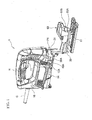
FIG 1 is a drawing that shows an overall perspective view of a jigsaw according to an embodiment of the present invention with a cover member removed from a housing. -
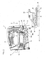
FIG 2 is a side view of the jigsaw with the cover member removed from the housing. -
FIG 3 is a bottom view of an essential portion of the jigsaw with the cover member removed from the housing. -
FIG 4 is a cross-sectional view of an essential portion of the jigsaw. - An embodiment of the present invention will be described with reference to
FIGS. 1 to 4 . A jigsaw 1 as shown inFIGS. 1 to 4 includes ahousing 10, arod 20, ablade 30, a first blow passage 40 (40A, 40B), a second blow passage 50 (50A, 50B), and acover member 60. The jigsaw 1 is one example of a cutting machine according to the present invention. - The
housing 10 is formed by assembling together left and right half housings made of resin. A handle H is provided on top of thehousing 10. The handle H accommodates a switch including atrigger 11 for activating and deactivating the jigsaw 1. A power cord C supplying power to the jigsaw 1 is attached at a rear end of the housing 10 (left side inFIGS. 1 to 4 ). - A motor M as a drive power source (see
FIG 4 ) is accommodated in a center portion of thehousing 10, and a reciprocating mechanism (not shown) is accommodated in a forward portion of the housing. An output shaft of the motor M is attached to a fan F for cooling the motor M, and meshes with a drive gear of the reciprocating mechanism. Further, in the forward portion of thehousing 10, arod 20 is reciprocably supported in an up-down direction Y (seeFIG 2 ) of thehousing 10 by the reciprocating mechanism, and a lower end portion of therod 20 projects downward from thehousing 10. The lower end portion of therod 20 is provided with ablade attachment portion 21, and a base end portion of thelinear blade 30 is detachably connected to theblade attachment portion 21. Theblade 30 is one example of a cutting blade according to the present invention, and theblade attachment portion 21 is one example of a connecting body according to the present invention. - As shown in
FIGS. 1 ,2 , and4 , anair outlet 12A is formed in a left side surface of thehousing 10 near a downwind side of the cooling fan F, while anair outlet 12B is formed in a right side surface of thehousing 10 near the downwind side. Thefirst blow passage 40A and thesecond blow passage 50A are formed branching from theair outlet 12A in the left side surface, as shown inFIGS. 1 and2 . Further, thefirst blow passage 40B and thesecond blow passage 50B are formed branching from theair outlet 12B in the right side surface. It should be noted that the top side ofFIG 4 corresponds the left side of thehousing 10, and the bottom side ofFIG 4 corresponds the right side of thehousing 10. - The
first blow passage 40A is formed as a recessed groove extending in a front-rear direction X of thehousing 10 on the left side surface of thehousing 10. An upstream end of thefirst blow passage 40A communicates with theair outlet 12A, and a downstream end of thefirst blow passage 40A opens toward a front surface of thehousing 10 and extends from a left rear side of therod 20 toward a top dead center position P1 of theblade attachment portion 21. Meanwhile, thefirst blow passage 40B is formed as a recessed groove extending in the front-rear direction X on the right side surface of thehousing 10. An upstream end of thefirst blow passage 40B communicates with theair outlet 12B, and a downstream end of thefirst blow passage 40B opens similar to thefirst blow passage 40A and extends from a right rear side of therod 20 toward the top dead center position P1. Thefirst blow passages - As shown in
FIGS. 1 to 3 , thesecond blow passage 50A is formed as a recessed groove which is inclined forward and extends along the left side surface of thehousing 10 toward a cutting place P2 of a workpiece W. An upstream end of thesecond blow passage 50A communicates with theair outlet 12A, and a downstream end of thesecond blow passage 50A opens toward a bottom surface of thehousing 10 and extends from a left rear side of theblade 30 toward the cutting place P2. - The
second blow passage 50B is formed as a recessed groove which is inclined forward and extends along the right side surface of thehousing 10 toward the cutting place P2. An upstream end of thesecond blow passage 50B communicates with theair outlet 12B, and a downstream end of thesecond blow passage 50B opens similar to thesecond blow passage 50A and extends from a right rear side of theblade 30 toward the cutting place P2. It should be noted that the top side ofFIG 3 corresponds the left side of thehousing 10 and the left side of theblade 30, and the bottom side ofFIG 3 corresponds the right side of thehousing 10 and the right side of theblade 30. - In a lower portion of the
housing 10, as shown inFIGS. 1 to 3 , a hollowdust collection passage 14 is formed extending in the front-rear direction X. Adust collection opening 15 is formed in a front lower surface of thedust collection passage 14. When a dust collector connected to thedust collection passage 14 operates, chips generated in the cutting place P2 are suctioned inside thedust collection passage 14 through thedust collection opening 15. - The
cover member 60 is threadably attached to the lower portion of thehousing 10. Thecover member 60 is made of aluminum and molded into a substantially U-shaped configuration as viewed from the front, as shown inFIGS. 3 and4 . Thecover member 60 covers, in a non-contacting manner, theair outlets first blow passages second blow passages housing 10, and the projecting section of therod 20 at the forward portion of thehousing 10. As shown inFIGS. 1 and4 , a front section of thecover member 60 is formed with aleft wall portion 60A that is continuous from a left side surface of thecover member 60 and projects diagonally forward and inward of thecover member 60, and aright wall portion 60B that is continuous from a right side surface of thecover member 60 and projects diagonally forward and inward of thecover member 60. After attaching thecover member 60 to thehousing 10, outer sides of each of theblow passages cover member 60. Theleft wall portion 60A projects toward the left side of therod 20, and theright wall portion 60B projects toward the right side of therod 20. As shown inFIGS. 1 and2 , abase 61 contacting an upper surface of the workpiece W is provided continuous from a lower portion of thecover member 60. - Next, the operation of the jigsaw 1 will be described. By contacting the base 61 with the upper surface of the workpiece W and pressing the
trigger 11 toward the inside of the handle H, the switch is set to an ON state and the motor M starts driving. The drive gear of the reciprocating mechanism rotates accordingly, and therod 20 and theblade 30 reciprocate in the up-down direction Y, thereby cutting the workpiece W along a cut line drawn on the workpiece W. In addition, driving of the motor M is accompanied by rotating of the cooling fan F, whereby air for cooling the motor M is suctioned inside thehousing 10 through an inlet of thehousing 10 and cools the motor M. The cooling air subsequently flows toward the downwind side of the cooling fan F, and such air is then blown from theair outlet 12A and guided toward thefirst blow passage 40A and thesecond blow passage 50A. The cooling air is also blown from theair outlet 12B and guided toward thefirst blow passage 40B and thesecond blow passage 50B. - The cooling air guided by the
second blow passages cover member 60 through a space between theblow passages first blow passage 40A flows along the inner surface of thecover member 60 and then flows from the left side of therod 20 in a direction intersecting therod 20 due to theleft wall portion 60A. Thus, the cooling air scatters the chips blown upward from the cutting place P2 forward therod 20. The cooling air guided by thefirst blow passage 40B similarly flows along the inner surface of thecover member 60 and then flows from the right side of therod 20 in a direction intersecting therod 20 due to theright wall portion 60B. Thus, the cooling air scatters the blown-upward chips forward therod 20. The cooling air flowing in this manner forwardly scatters the chips leftward and rightward therod 20, which can prevent the chips from heading toward the projecting section of therod 20. Thefirst blow passages - If the
blade 30 is reciprocated in the up-down direction Y to cut the workpiece W with the handle H placed at a bottom and thedust collection passage 14 placed at a top, the chips fall from the cutting place P2 toward the projecting section side of therod 20 located below. In this case as well, the cooling air which flows leftward and rightward therod 20 scatters the chips falling from the cutting place P2 forward therod 20 by the cooling air. Therefore, the chips can be prevented from entering thehousing 10 from the projecting section. - With the jigsaw 1 of the present embodiment, chips generated from the workpiece W being cut by the
blade 30 are scattered forward therod 20 by the cooling air from the downwind side of the cooling fan F. The cooling air flows in two directions of which one is guided through theair outlet 12A to thefirst blow passage 40A, and the other is guided through theair outlet 12B to thefirst blow passage 40B. Therefore, the chips can be prevented from entering thehousing 10 from the projecting section of therod 20 in thehousing 10. - When the cooling air guided toward the
first blow passages rod 20, the chips are scattered forward from both the left and right sides of therod 20. Therefore, the chips are blocked from heading toward the projecting section on thehousing 10 from the leftward and rightward of therod 20, so that the chips can be effectively prevented from entering thehousing 10 from the projecting section. - The chips generated in the cutting place P2 are scattered by the cooling air from the downwind side of the cooling fan F. The cooling air is guided through the
air outlet 12A to thesecond blow passage 50A and through theair outlet 12B to thesecond blow passage 50B. Therefore, a user can keep sight of a cut line drawn on the workpiece and an edge of the cutting blade when the cutting blade cuts the workpiece. As a result, better visibility of the blade edge and the cut line (cutting position) can be achieved, which increases in the efficiency of the cutting operation. - In addition, the
first blow passage 40A and thesecond blow passage 50A are formed branching from theair outlet 12A formed near the downwind side of the cooling fan F. Therefore, theblow passages first blow passage 40A and thesecond blow passage 50A are formed separately. Thus, theblow passages - The
first blow passage 40B and thesecond blow passage 50B are also formed branching from theair outlet 12B formed near the downwind side. Therefore, theblow passages blow passages - The cooling air guided toward the
first blow passages housing 10 and the inner surface of thecover member 60 along the inner surface, and is guided toward therod 20. Meanwhile, the cooling air guided toward thesecond blow passages housing 10 and the inner surface of thecover member 60, and is guided toward the cutting place P2. Therefore, the cooling air can be reliably guided toward therod 20 and the cutting place P2 without being affected by the flow of air around the jigsaw 1. - The present invention is not limited to the embodiment described above, and a configuration thereof may be partially modified as appropriate and practiced without departing from the scope of the invention. For example, although the
first blow passages housing 10 in the embodiment described above, the present invention is not limited to this example. One first blow passage may be formed inside thehousing 10 as communicating with the downwind side of the cooling fan F, and the downstream end of the first blow passage may open directly behind therod 20 and blow the cooling air such that the cooling air flows forwardly in a direction perpendicular to therod 20. Alternatively, two or more first blow passages may be formed inside thehousing 10 as communicating with the downwind side of the cooling fan F, and the downstream ends of the first blow passages may open toward therod 20. - In addition, although the
second blow passages housing 10 in the embodiment described above, the present invention is not limited to this example. One second blow passage may be formed inside thehousing 10 as communicating with the downwind side of the cooling fan F, and the downstream end of the second blow passage may open in the bottom surface of thehousing 10 toward the cutting place P2. If the first blow passage is also formed inside thehousing 10 as described above, the second blow passage may be formed branching with the first blow passage from the downwind side of the cooling fan F inside thehousing 10. - Moreover, in the embodiment described above, the
first blow passage 40A (40B) and thesecond blow passage 50A (50B) are each formed branching from theair outlet 12A (12B). However, the present invention is not limited to this example. As another example, one first blow passage and two or more second blow passages may be formed branching from therespective air outlets - It is explicitly stated that all features disclosed in the description and/or the claims are intended to be disclosed separately and independently from each other for the purpose of original disclosure as well as for the purpose of restricting the claimed invention independent of the composition of the features in the embodiments and/or the claims. It is explicitly stated that all value ranges or indications of groups of entities disclose every possible intermediate value or intermediate entity for the purpose of original disclosure as well as for the purpose of restricting the claimed invention, in particular as limits of value ranges.
Claims (15)
- A cutting machine (1), in which a reciprocating rod (20) is driven by a motor (M) and projects downward at a forward portion of a housing (10) that accommodates the motor (M) and a cooling fan (F) for cooling the motor (M), and a lower end of the rod (20) is connected to a cutting blade (30) for cutting a workpiece (W), the cutting machine (1) characterized in that
the housing (10) is formed with a first blow passage (40) and cooling air generated by the cooling fan (F) forwardly flows through the first blow passage in a direction intersecting the rod (20) from a rear side relative to the rod (20). - The cutting machine (1) according to claim 1, wherein
a pair of the first blow passages (40A, 40B) is provided in the housing (10) and the cooling air flows through the first blow passages (40A, 40B) leftward and rightward from the rear side of the rod (20). - The cutting machine (1) according to claim 1 or 2, wherein
a second blow passage (50A, 50B) is provided and the cooling air flows through the second blow passage (50A, 50B) toward a cutting region (P2) of the workpiece (W) being cut by the cutting blade (30). - The cutting machine (1) according to claim 3, wherein
the first blow passage (40A, 40B) and the second blow passage (50A, 50B) are formed branching from a downwind side of the cooling fan (F). - The cutting machine (1) according to claim 3 or 4, further comprising:a cover member (60) that is attached to a lower portion of the housing (10), and covers from the first blow passage (40A, 40B) and the second blow passage (50A, 50B) to the forward portion of the housing (10), whereinbetween an outer surface of the housing (10) and an inner surface of the cover member (60), the cooling air blown from the first blow passage (40A, 40B) is guided toward the rod (20) and the cooling air blown from the second blow passage (50A, 50B) is guided toward the cutting region (P2).
- The cutting machine (1) according to any one of claims 3 to 5, wherein
an air outlet (12A, 12B) from which the cooling air blows is formed on each of left and right side surfaces of the housing (10) on the downwind side of the cooling fan (F), and the first blow passage (40A, 40B) and the second blow passage (50A, 50B) are formed branching from the air outlet (12A, 12B) on each of the left and right side surfaces. - The cutting machine (1) according to claim 6, wherein
the first blow passage (40A, 40B) and the second blow passage (50A, 50B) are each formed as a recessed groove. - The cutting machine (1) according to claim 6 or 7, wherein
an upstream end of the first blow passage (40A, 40B) communicates with the air outlet (12A, 12B), and a downstream end of the first blow passage (40A, 40B) is connected to a front surface of the housing (10) and opens toward the rod (20). - The cutting machine (1) according to claim 6 or 7, wherein
an upstream end of the second blow passage (50A, 50B) communicates with the air outlet (12A, 12B), and a downstream end of the second blow passage (50A, 50B) is connected to a bottom surface of the housing (10) and opens toward the cutting region (P2). - The cutting machine (1) according to claim 5, wherein
with the cover member (60) attached to the lower portion of the housing (10), a front end edge of the cover member (60) is formed with a left wall portion (60A) that is continuous from a left side surface of the cover member (60) and projects toward a left side of the rod (20), and formed with a right wall portion (60B) that is continuous from a right side surface of the cover member (60) and projects toward a right side of the rod (20). - The cutting machine (1) according to claim 5 or 10, wherein
a base (61) that projects downward and contacts an upper surface of the workpiece (W) is provided continuous from the cover member (60). - The cutting machine (1) according to any one of claims 1 to 11, wherein the lower end of the rod (20) is connected through a connecting body (21) to the cutting blade, and cooling air generated by the cooling fan (F) flows through the first blow passage (40A, 40B) toward the connecting body (21) at a top dead center position (P1).
- The cutting machine (1) according to claim 12, wherein
an air outlet (12A, 12B) from which the cooling air blows is formed on each of left and right side surfaces of the housing (10) on a downwind side of the cooling fan (F), and the first blow passage (40A, 40B) is formed as a recessed groove on each of the left and right side surfaces, wherein an upstream end of the first blow passage (40A, 40B) communicates with the air outlet (12A, 12B), and a downstream end of the first blow passage (40A, 40B) is connected to a front surface of the housing (10) and opens toward the connecting body (21). - A cutting machine (1), in which a reciprocating rod (20) is driven by a motor (M) and projects downward at a forward portion of a housing (10) that accommodates the motor (M) and a cooling fan (F) for cooling the motor (M), and a lower end of the rod (20) is connected through a connecting body (21) to a cutting blade (30) for cutting a workpiece (W), the cutting machine (1) characterized in that a blow passage (40A, 40B) is formed in the housing (10) and cooling air generated by the cooling fan (F) flows through the blow passage (40A, 40B) toward the connecting body (21) at a top dead center position (P1).
- The cutting machine (1) according to claim 14, wherein
an air outlet (12A, 12B) from which the cooling air blows is formed on each of left and right side surfaces of the housing (10) on a downwind side of the cooling fan (F), and the blow passage (40A, 40B) is formed as a recessed groove on each of the left and right side surfaces, wherein an upstream end of the blow passage (40A, 40B) communicates with the air outlet (12A, 12B), and a downstream end of the blow passage (40A, 40B) is connected to a front surface of the housing (10) and opens toward the connecting body (21).
Applications Claiming Priority (1)
| Application Number | Priority Date | Filing Date | Title |
|---|---|---|---|
| JP2010275945A JP5654859B2 (en) | 2010-12-10 | 2010-12-10 | Cutting machine |
Publications (2)
| Publication Number | Publication Date |
|---|---|
| EP2463049A1 true EP2463049A1 (en) | 2012-06-13 |
| EP2463049B1 EP2463049B1 (en) | 2016-09-28 |
Family
ID=45092250
Family Applications (1)
| Application Number | Title | Priority Date | Filing Date |
|---|---|---|---|
| EP11190537.8A Active EP2463049B1 (en) | 2010-12-10 | 2011-11-24 | Cutting machine |
Country Status (5)
| Country | Link |
|---|---|
| US (1) | US20120144681A1 (en) |
| EP (1) | EP2463049B1 (en) |
| JP (1) | JP5654859B2 (en) |
| CN (1) | CN102554346B (en) |
| RU (1) | RU2011150222A (en) |
Families Citing this family (4)
| Publication number | Priority date | Publication date | Assignee | Title |
|---|---|---|---|---|
| JP6924577B2 (en) | 2017-01-13 | 2021-08-25 | 株式会社マキタ | Jigsaw |
| JP6824755B2 (en) | 2017-01-13 | 2021-02-03 | 株式会社マキタ | Jigsaw |
| CN109222127A (en) * | 2018-11-30 | 2019-01-18 | 泉州恒灼热力机械科技有限公司 | A kind of coconut husk tapping machine of milling cutter type |
| JP7588017B2 (en) * | 2021-03-26 | 2024-11-21 | 株式会社マキタ | Reciprocating cutting tool |
Citations (6)
| Publication number | Priority date | Publication date | Assignee | Title |
|---|---|---|---|---|
| US2631619A (en) * | 1949-09-03 | 1953-03-17 | Rcs Engineering Corp | Reciprocating saw tool attachment |
| US3832772A (en) * | 1972-06-02 | 1974-09-03 | Shapiro Leonard U | Pneumatic hand tool |
| DE7919565U1 (en) * | 1979-07-07 | 1979-10-25 | Ohlsen, Harald, 2100 Hamburg | Device for blowing out saw cut surfaces |
| US4730397A (en) * | 1985-08-09 | 1988-03-15 | Black & Decker, Inc. | Jig saw with two-piece shoe |
| EP1790432A1 (en) * | 2005-11-28 | 2007-05-30 | Black & Decker, Inc. | Power toll such as jig saw having means for removing cutting debris from workpiece |
| JP4248766B2 (en) | 2001-05-23 | 2009-04-02 | 株式会社マキタ | Reciprocating cutting tool |
Family Cites Families (7)
| Publication number | Priority date | Publication date | Assignee | Title |
|---|---|---|---|---|
| US2639737A (en) * | 1948-07-03 | 1953-05-26 | Harold S Forsberg | Motor driven reciprocating saw |
| US3085603A (en) * | 1961-09-01 | 1963-04-16 | Black & Decker Mfg Co | Auxiliary cooling means for portable electric jig saw |
| US3206989A (en) * | 1963-05-21 | 1965-09-21 | Black & Decker Mfg Co | Arcuate motion jig saw |
| JPS6046204U (en) * | 1983-09-02 | 1985-04-01 | 株式会社 マキタ電機製作所 | electric saw |
| JPS62117018U (en) * | 1986-01-17 | 1987-07-25 | ||
| JPH02117823U (en) * | 1989-03-10 | 1990-09-20 | ||
| US20030121389A1 (en) * | 2002-01-02 | 2003-07-03 | Wheeler Thomas J. | Reciprocating saw |
-
2010
- 2010-12-10 JP JP2010275945A patent/JP5654859B2/en active Active
-
2011
- 2011-11-08 US US13/291,501 patent/US20120144681A1/en not_active Abandoned
- 2011-11-18 CN CN201110374884.3A patent/CN102554346B/en active Active
- 2011-11-24 EP EP11190537.8A patent/EP2463049B1/en active Active
- 2011-12-09 RU RU2011150222/02A patent/RU2011150222A/en not_active Application Discontinuation
Patent Citations (6)
| Publication number | Priority date | Publication date | Assignee | Title |
|---|---|---|---|---|
| US2631619A (en) * | 1949-09-03 | 1953-03-17 | Rcs Engineering Corp | Reciprocating saw tool attachment |
| US3832772A (en) * | 1972-06-02 | 1974-09-03 | Shapiro Leonard U | Pneumatic hand tool |
| DE7919565U1 (en) * | 1979-07-07 | 1979-10-25 | Ohlsen, Harald, 2100 Hamburg | Device for blowing out saw cut surfaces |
| US4730397A (en) * | 1985-08-09 | 1988-03-15 | Black & Decker, Inc. | Jig saw with two-piece shoe |
| JP4248766B2 (en) | 2001-05-23 | 2009-04-02 | 株式会社マキタ | Reciprocating cutting tool |
| EP1790432A1 (en) * | 2005-11-28 | 2007-05-30 | Black & Decker, Inc. | Power toll such as jig saw having means for removing cutting debris from workpiece |
Also Published As
| Publication number | Publication date |
|---|---|
| CN102554346B (en) | 2015-09-09 |
| JP5654859B2 (en) | 2015-01-14 |
| RU2011150222A (en) | 2013-06-20 |
| EP2463049B1 (en) | 2016-09-28 |
| US20120144681A1 (en) | 2012-06-14 |
| JP2012121116A (en) | 2012-06-28 |
| CN102554346A (en) | 2012-07-11 |
Similar Documents
| Publication | Publication Date | Title |
|---|---|---|
| US11648656B2 (en) | Electric handheld working machine | |
| CN106163751B (en) | Air-flow and lighting system for bench saw | |
| EP1415746B1 (en) | Power tool | |
| CN101524853B (en) | Sawing machine | |
| EP2463049B1 (en) | Cutting machine | |
| KR102541105B1 (en) | Handheld machine tool with suction linkage | |
| US12145205B2 (en) | Electric circular saw | |
| EP1834723B1 (en) | Jigsaw with chips removal apparatus | |
| EP2679325A1 (en) | Jigsaw | |
| EP1790432B1 (en) | Power toll such as jig saw having means for removing cutting debris from workpiece | |
| EP2886233A1 (en) | Power circular saw | |
| CN115570631B (en) | Miter saws and power tools | |
| US20070033807A1 (en) | Planer with improved chip removal | |
| CN113118549A (en) | Electric circular saw | |
| US9931704B2 (en) | Line-of-sight blower for a power tool | |
| CN206690029U (en) | Power tool and its drifting dust part | |
| CN108262719A (en) | Power tool and its drifting dust component | |
| CN220146013U (en) | Haircut component capable of collecting broken hair | |
| GB2462365A (en) | Hand-held power tool with blowing duct | |
| CN104029181B (en) | hand tool | |
| JP2018058125A (en) | Electric tool | |
| JP2005230977A (en) | Cutting tool | |
| JP2001058302A (en) | Chip collecting device for undercut circular sawing machine |
Legal Events
| Date | Code | Title | Description |
|---|---|---|---|
| PUAI | Public reference made under article 153(3) epc to a published international application that has entered the european phase |
Free format text: ORIGINAL CODE: 0009012 |
|
| AK | Designated contracting states |
Kind code of ref document: A1 Designated state(s): AL AT BE BG CH CY CZ DE DK EE ES FI FR GB GR HR HU IE IS IT LI LT LU LV MC MK MT NL NO PL PT RO RS SE SI SK SM TR |
|
| AX | Request for extension of the european patent |
Extension state: BA ME |
|
| 17P | Request for examination filed |
Effective date: 20121204 |
|
| 17Q | First examination report despatched |
Effective date: 20150624 |
|
| GRAP | Despatch of communication of intention to grant a patent |
Free format text: ORIGINAL CODE: EPIDOSNIGR1 |
|
| INTG | Intention to grant announced |
Effective date: 20160203 |
|
| GRAJ | Information related to disapproval of communication of intention to grant by the applicant or resumption of examination proceedings by the epo deleted |
Free format text: ORIGINAL CODE: EPIDOSDIGR1 |
|
| GRAP | Despatch of communication of intention to grant a patent |
Free format text: ORIGINAL CODE: EPIDOSNIGR1 |
|
| GRAP | Despatch of communication of intention to grant a patent |
Free format text: ORIGINAL CODE: EPIDOSNIGR1 |
|
| GRAS | Grant fee paid |
Free format text: ORIGINAL CODE: EPIDOSNIGR3 |
|
| INTG | Intention to grant announced |
Effective date: 20160520 |
|
| GRAA | (expected) grant |
Free format text: ORIGINAL CODE: 0009210 |
|
| RIN1 | Information on inventor provided before grant (corrected) |
Inventor name: INAI, MASAHIKO Inventor name: HAYASHI, MASANORI |
|
| AK | Designated contracting states |
Kind code of ref document: B1 Designated state(s): AL AT BE BG CH CY CZ DE DK EE ES FI FR GB GR HR HU IE IS IT LI LT LU LV MC MK MT NL NO PL PT RO RS SE SI SK SM TR |
|
| REG | Reference to a national code |
Ref country code: GB Ref legal event code: FG4D |
|
| REG | Reference to a national code |
Ref country code: CH Ref legal event code: EP |
|
| REG | Reference to a national code |
Ref country code: AT Ref legal event code: REF Ref document number: 832318 Country of ref document: AT Kind code of ref document: T Effective date: 20161015 |
|
| REG | Reference to a national code |
Ref country code: IE Ref legal event code: FG4D |
|
| REG | Reference to a national code |
Ref country code: DE Ref legal event code: R096 Ref document number: 602011030719 Country of ref document: DE |
|
| REG | Reference to a national code |
Ref country code: FR Ref legal event code: PLFP Year of fee payment: 6 |
|
| REG | Reference to a national code |
Ref country code: LT Ref legal event code: MG4D |
|
| PG25 | Lapsed in a contracting state [announced via postgrant information from national office to epo] |
Ref country code: LT Free format text: LAPSE BECAUSE OF FAILURE TO SUBMIT A TRANSLATION OF THE DESCRIPTION OR TO PAY THE FEE WITHIN THE PRESCRIBED TIME-LIMIT Effective date: 20160928 Ref country code: HR Free format text: LAPSE BECAUSE OF FAILURE TO SUBMIT A TRANSLATION OF THE DESCRIPTION OR TO PAY THE FEE WITHIN THE PRESCRIBED TIME-LIMIT Effective date: 20160928 Ref country code: FI Free format text: LAPSE BECAUSE OF FAILURE TO SUBMIT A TRANSLATION OF THE DESCRIPTION OR TO PAY THE FEE WITHIN THE PRESCRIBED TIME-LIMIT Effective date: 20160928 Ref country code: RS Free format text: LAPSE BECAUSE OF FAILURE TO SUBMIT A TRANSLATION OF THE DESCRIPTION OR TO PAY THE FEE WITHIN THE PRESCRIBED TIME-LIMIT Effective date: 20160928 Ref country code: NO Free format text: LAPSE BECAUSE OF FAILURE TO SUBMIT A TRANSLATION OF THE DESCRIPTION OR TO PAY THE FEE WITHIN THE PRESCRIBED TIME-LIMIT Effective date: 20161228 |
|
| REG | Reference to a national code |
Ref country code: NL Ref legal event code: MP Effective date: 20160928 |
|
| REG | Reference to a national code |
Ref country code: AT Ref legal event code: MK05 Ref document number: 832318 Country of ref document: AT Kind code of ref document: T Effective date: 20160928 |
|
| PG25 | Lapsed in a contracting state [announced via postgrant information from national office to epo] |
Ref country code: BE Free format text: LAPSE BECAUSE OF NON-PAYMENT OF DUE FEES Effective date: 20161130 Ref country code: GR Free format text: LAPSE BECAUSE OF FAILURE TO SUBMIT A TRANSLATION OF THE DESCRIPTION OR TO PAY THE FEE WITHIN THE PRESCRIBED TIME-LIMIT Effective date: 20161229 Ref country code: SE Free format text: LAPSE BECAUSE OF FAILURE TO SUBMIT A TRANSLATION OF THE DESCRIPTION OR TO PAY THE FEE WITHIN THE PRESCRIBED TIME-LIMIT Effective date: 20160928 Ref country code: LV Free format text: LAPSE BECAUSE OF FAILURE TO SUBMIT A TRANSLATION OF THE DESCRIPTION OR TO PAY THE FEE WITHIN THE PRESCRIBED TIME-LIMIT Effective date: 20160928 Ref country code: NL Free format text: LAPSE BECAUSE OF FAILURE TO SUBMIT A TRANSLATION OF THE DESCRIPTION OR TO PAY THE FEE WITHIN THE PRESCRIBED TIME-LIMIT Effective date: 20160928 |
|
| PG25 | Lapsed in a contracting state [announced via postgrant information from national office to epo] |
Ref country code: RO Free format text: LAPSE BECAUSE OF FAILURE TO SUBMIT A TRANSLATION OF THE DESCRIPTION OR TO PAY THE FEE WITHIN THE PRESCRIBED TIME-LIMIT Effective date: 20160928 Ref country code: EE Free format text: LAPSE BECAUSE OF FAILURE TO SUBMIT A TRANSLATION OF THE DESCRIPTION OR TO PAY THE FEE WITHIN THE PRESCRIBED TIME-LIMIT Effective date: 20160928 |
|
| PG25 | Lapsed in a contracting state [announced via postgrant information from national office to epo] |
Ref country code: PT Free format text: LAPSE BECAUSE OF FAILURE TO SUBMIT A TRANSLATION OF THE DESCRIPTION OR TO PAY THE FEE WITHIN THE PRESCRIBED TIME-LIMIT Effective date: 20170130 Ref country code: CZ Free format text: LAPSE BECAUSE OF FAILURE TO SUBMIT A TRANSLATION OF THE DESCRIPTION OR TO PAY THE FEE WITHIN THE PRESCRIBED TIME-LIMIT Effective date: 20160928 Ref country code: BG Free format text: LAPSE BECAUSE OF FAILURE TO SUBMIT A TRANSLATION OF THE DESCRIPTION OR TO PAY THE FEE WITHIN THE PRESCRIBED TIME-LIMIT Effective date: 20161228 Ref country code: BE Free format text: LAPSE BECAUSE OF FAILURE TO SUBMIT A TRANSLATION OF THE DESCRIPTION OR TO PAY THE FEE WITHIN THE PRESCRIBED TIME-LIMIT Effective date: 20160928 Ref country code: IS Free format text: LAPSE BECAUSE OF FAILURE TO SUBMIT A TRANSLATION OF THE DESCRIPTION OR TO PAY THE FEE WITHIN THE PRESCRIBED TIME-LIMIT Effective date: 20170128 Ref country code: ES Free format text: LAPSE BECAUSE OF FAILURE TO SUBMIT A TRANSLATION OF THE DESCRIPTION OR TO PAY THE FEE WITHIN THE PRESCRIBED TIME-LIMIT Effective date: 20160928 Ref country code: SK Free format text: LAPSE BECAUSE OF FAILURE TO SUBMIT A TRANSLATION OF THE DESCRIPTION OR TO PAY THE FEE WITHIN THE PRESCRIBED TIME-LIMIT Effective date: 20160928 Ref country code: SM Free format text: LAPSE BECAUSE OF FAILURE TO SUBMIT A TRANSLATION OF THE DESCRIPTION OR TO PAY THE FEE WITHIN THE PRESCRIBED TIME-LIMIT Effective date: 20160928 Ref country code: AT Free format text: LAPSE BECAUSE OF FAILURE TO SUBMIT A TRANSLATION OF THE DESCRIPTION OR TO PAY THE FEE WITHIN THE PRESCRIBED TIME-LIMIT Effective date: 20160928 Ref country code: PL Free format text: LAPSE BECAUSE OF FAILURE TO SUBMIT A TRANSLATION OF THE DESCRIPTION OR TO PAY THE FEE WITHIN THE PRESCRIBED TIME-LIMIT Effective date: 20160928 |
|
| REG | Reference to a national code |
Ref country code: DE Ref legal event code: R097 Ref document number: 602011030719 Country of ref document: DE |
|
| PG25 | Lapsed in a contracting state [announced via postgrant information from national office to epo] |
Ref country code: IT Free format text: LAPSE BECAUSE OF FAILURE TO SUBMIT A TRANSLATION OF THE DESCRIPTION OR TO PAY THE FEE WITHIN THE PRESCRIBED TIME-LIMIT Effective date: 20160928 |
|
| REG | Reference to a national code |
Ref country code: CH Ref legal event code: PL |
|
| PG25 | Lapsed in a contracting state [announced via postgrant information from national office to epo] |
Ref country code: CH Free format text: LAPSE BECAUSE OF NON-PAYMENT OF DUE FEES Effective date: 20161130 Ref country code: LI Free format text: LAPSE BECAUSE OF NON-PAYMENT OF DUE FEES Effective date: 20161130 Ref country code: DK Free format text: LAPSE BECAUSE OF FAILURE TO SUBMIT A TRANSLATION OF THE DESCRIPTION OR TO PAY THE FEE WITHIN THE PRESCRIBED TIME-LIMIT Effective date: 20160928 |
|
| PLBE | No opposition filed within time limit |
Free format text: ORIGINAL CODE: 0009261 |
|
| STAA | Information on the status of an ep patent application or granted ep patent |
Free format text: STATUS: NO OPPOSITION FILED WITHIN TIME LIMIT |
|
| REG | Reference to a national code |
Ref country code: IE Ref legal event code: MM4A |
|
| 26N | No opposition filed |
Effective date: 20170629 |
|
| PG25 | Lapsed in a contracting state [announced via postgrant information from national office to epo] |
Ref country code: LU Free format text: LAPSE BECAUSE OF NON-PAYMENT OF DUE FEES Effective date: 20161130 |
|
| REG | Reference to a national code |
Ref country code: FR Ref legal event code: PLFP Year of fee payment: 7 |
|
| PG25 | Lapsed in a contracting state [announced via postgrant information from national office to epo] |
Ref country code: SI Free format text: LAPSE BECAUSE OF FAILURE TO SUBMIT A TRANSLATION OF THE DESCRIPTION OR TO PAY THE FEE WITHIN THE PRESCRIBED TIME-LIMIT Effective date: 20160928 Ref country code: IE Free format text: LAPSE BECAUSE OF NON-PAYMENT OF DUE FEES Effective date: 20161124 |
|
| PG25 | Lapsed in a contracting state [announced via postgrant information from national office to epo] |
Ref country code: HU Free format text: LAPSE BECAUSE OF FAILURE TO SUBMIT A TRANSLATION OF THE DESCRIPTION OR TO PAY THE FEE WITHIN THE PRESCRIBED TIME-LIMIT; INVALID AB INITIO Effective date: 20111124 Ref country code: CY Free format text: LAPSE BECAUSE OF FAILURE TO SUBMIT A TRANSLATION OF THE DESCRIPTION OR TO PAY THE FEE WITHIN THE PRESCRIBED TIME-LIMIT Effective date: 20160928 |
|
| PG25 | Lapsed in a contracting state [announced via postgrant information from national office to epo] |
Ref country code: MC Free format text: LAPSE BECAUSE OF FAILURE TO SUBMIT A TRANSLATION OF THE DESCRIPTION OR TO PAY THE FEE WITHIN THE PRESCRIBED TIME-LIMIT Effective date: 20160928 Ref country code: MK Free format text: LAPSE BECAUSE OF FAILURE TO SUBMIT A TRANSLATION OF THE DESCRIPTION OR TO PAY THE FEE WITHIN THE PRESCRIBED TIME-LIMIT Effective date: 20160928 Ref country code: TR Free format text: LAPSE BECAUSE OF FAILURE TO SUBMIT A TRANSLATION OF THE DESCRIPTION OR TO PAY THE FEE WITHIN THE PRESCRIBED TIME-LIMIT Effective date: 20160928 |
|
| PG25 | Lapsed in a contracting state [announced via postgrant information from national office to epo] |
Ref country code: MT Free format text: LAPSE BECAUSE OF NON-PAYMENT OF DUE FEES Effective date: 20161124 |
|
| REG | Reference to a national code |
Ref country code: FR Ref legal event code: PLFP Year of fee payment: 8 |
|
| PG25 | Lapsed in a contracting state [announced via postgrant information from national office to epo] |
Ref country code: AL Free format text: LAPSE BECAUSE OF FAILURE TO SUBMIT A TRANSLATION OF THE DESCRIPTION OR TO PAY THE FEE WITHIN THE PRESCRIBED TIME-LIMIT Effective date: 20160928 |
|
| PGFP | Annual fee paid to national office [announced via postgrant information from national office to epo] |
Ref country code: FR Payment date: 20250930 Year of fee payment: 15 |
|
| PGFP | Annual fee paid to national office [announced via postgrant information from national office to epo] |
Ref country code: DE Payment date: 20250930 Year of fee payment: 15 |
|
| PGFP | Annual fee paid to national office [announced via postgrant information from national office to epo] |
Ref country code: GB Payment date: 20251001 Year of fee payment: 15 |