EP2463048B1 - Cutting machine - Google Patents
Cutting machine Download PDFInfo
- Publication number
- EP2463048B1 EP2463048B1 EP10806062.5A EP10806062A EP2463048B1 EP 2463048 B1 EP2463048 B1 EP 2463048B1 EP 10806062 A EP10806062 A EP 10806062A EP 2463048 B1 EP2463048 B1 EP 2463048B1
- Authority
- EP
- European Patent Office
- Prior art keywords
- saw blade
- cutting machine
- operating element
- disposed
- worktable
- Prior art date
- Legal status (The legal status is an assumption and is not a legal conclusion. Google has not performed a legal analysis and makes no representation as to the accuracy of the status listed.)
- Not-in-force
Links
- 238000005520 cutting process Methods 0.000 title claims description 60
- 238000003825 pressing Methods 0.000 claims description 81
- 238000006243 chemical reaction Methods 0.000 claims description 6
- 239000000428 dust Substances 0.000 description 5
- 238000000034 method Methods 0.000 description 4
- 230000004323 axial length Effects 0.000 description 1
- 230000006835 compression Effects 0.000 description 1
- 238000007906 compression Methods 0.000 description 1
- 239000000463 material Substances 0.000 description 1
- 238000003466 welding Methods 0.000 description 1
Images






Classifications
-
- B—PERFORMING OPERATIONS; TRANSPORTING
- B23—MACHINE TOOLS; METAL-WORKING NOT OTHERWISE PROVIDED FOR
- B23D—PLANING; SLOTTING; SHEARING; BROACHING; SAWING; FILING; SCRAPING; LIKE OPERATIONS FOR WORKING METAL BY REMOVING MATERIAL, NOT OTHERWISE PROVIDED FOR
- B23D49/00—Machines or devices for sawing with straight reciprocating saw blades, e.g. hacksaws
- B23D49/08—Pad-saw machines, i.e. machines in which the blade is attached to a carrier at one end only
-
- B—PERFORMING OPERATIONS; TRANSPORTING
- B23—MACHINE TOOLS; METAL-WORKING NOT OTHERWISE PROVIDED FOR
- B23D—PLANING; SLOTTING; SHEARING; BROACHING; SAWING; FILING; SCRAPING; LIKE OPERATIONS FOR WORKING METAL BY REMOVING MATERIAL, NOT OTHERWISE PROVIDED FOR
- B23D51/00—Sawing machines or sawing devices working with straight blades, characterised only by constructional features of particular parts; Carrying or attaching means for tools, covered by this subclass, which are connected to a carrier at both ends
- B23D51/02—Sawing machines or sawing devices working with straight blades, characterised only by constructional features of particular parts; Carrying or attaching means for tools, covered by this subclass, which are connected to a carrier at both ends of beds; of guiding arrangements for work-tables or saw carriers; of frames
-
- B—PERFORMING OPERATIONS; TRANSPORTING
- B23—MACHINE TOOLS; METAL-WORKING NOT OTHERWISE PROVIDED FOR
- B23D—PLANING; SLOTTING; SHEARING; BROACHING; SAWING; FILING; SCRAPING; LIKE OPERATIONS FOR WORKING METAL BY REMOVING MATERIAL, NOT OTHERWISE PROVIDED FOR
- B23D51/00—Sawing machines or sawing devices working with straight blades, characterised only by constructional features of particular parts; Carrying or attaching means for tools, covered by this subclass, which are connected to a carrier at both ends
- B23D51/08—Sawing machines or sawing devices working with straight blades, characterised only by constructional features of particular parts; Carrying or attaching means for tools, covered by this subclass, which are connected to a carrier at both ends of devices for mounting straight saw blades or other tools
-
- B—PERFORMING OPERATIONS; TRANSPORTING
- B26—HAND CUTTING TOOLS; CUTTING; SEVERING
- B26D—CUTTING; DETAILS COMMON TO MACHINES FOR PERFORATING, PUNCHING, CUTTING-OUT, STAMPING-OUT OR SEVERING
- B26D7/00—Details of apparatus for cutting, cutting-out, stamping-out, punching, perforating, or severing by means other than cutting
- B26D7/26—Means for mounting or adjusting the cutting member; Means for adjusting the stroke of the cutting member
- B26D7/2614—Means for mounting the cutting member
-
- Y—GENERAL TAGGING OF NEW TECHNOLOGICAL DEVELOPMENTS; GENERAL TAGGING OF CROSS-SECTIONAL TECHNOLOGIES SPANNING OVER SEVERAL SECTIONS OF THE IPC; TECHNICAL SUBJECTS COVERED BY FORMER USPC CROSS-REFERENCE ART COLLECTIONS [XRACs] AND DIGESTS
- Y10—TECHNICAL SUBJECTS COVERED BY FORMER USPC
- Y10T—TECHNICAL SUBJECTS COVERED BY FORMER US CLASSIFICATION
- Y10T83/00—Cutting
- Y10T83/687—By tool reciprocable along elongated edge
-
- Y—GENERAL TAGGING OF NEW TECHNOLOGICAL DEVELOPMENTS; GENERAL TAGGING OF CROSS-SECTIONAL TECHNOLOGIES SPANNING OVER SEVERAL SECTIONS OF THE IPC; TECHNICAL SUBJECTS COVERED BY FORMER USPC CROSS-REFERENCE ART COLLECTIONS [XRACs] AND DIGESTS
- Y10—TECHNICAL SUBJECTS COVERED BY FORMER USPC
- Y10T—TECHNICAL SUBJECTS COVERED BY FORMER US CLASSIFICATION
- Y10T83/00—Cutting
- Y10T83/687—By tool reciprocable along elongated edge
- Y10T83/704—With work-support and means to vary relationship between tool and work support
Definitions
- the invention relates to a cutting machine, in particular to a cutting machine with a reciprocating cutting mechanism.
- a jig saw comprises a motor, a housing holding the motor, a motion conversion mechanism that is housed in the gearbox housing, driven by the motor and converting the rotation motion of the motor into the reciprocating motion of a reciprocating rod, a saw blade connecting to the reciprocating rod via a clamp, and a bottom plate supporting the jig saw body on the surface of a workpiece.
- the current upside-down jig saw is configured by directly turning the jig jaw available in the market and mounting the jig jaw on a worktable with a certain connecting mechanism.
- the saw clamp of the jig saw is an inseparable structure of the jig saw and is disposed below the worktable together with the jig saw body, so when the saw blade is required to the replaced, the operator is required to stretch out his/her hands below the worktable to operate the clamp so as to replace the saw blade. The operator is required to stoop and try to find the clamp by hand. Therefore, the saw blade is inconvenient to replace, and the operation needs much time and labor.
- the object of the present invention is to provide a cutting machine according to claim 1, which is easy to be operated.
- the present invention provides a cutting machine comprising:
- the operating element is disposed on the upper surface of the worktable.
- the saw blade clamp comprises a clamping wrench rotating around a reciprocating rod axis of the reciprocating rod, a linkage mechanism is disposed between the operating element and the clamping wrench, and thus the operating element is operable to drive the clamping wrench rotating.
- the linkage mechanism comprises a connecting plate connected to the operating element and rotating around a rotating axis which is parallel to the reciprocating rod axis, and an actuating element being connected to the connecting plate and driving the clamping wrench moving.
- the rotating axis of the connecting plate is parallel to the rotating axis of the actuating element.
- the rotating axis of the connecting plate rotates around the rotating axis of the actuating element.
- the actuating element comprises a rotating frame being disposed rotatablely with respect to the reciprocating rod, the rotating frame comprises a C-shape base portion, a connecting shaft is disposed at one end of the base portion, a pushing column which extends vertically is disposed at the other end of the base portion, and a connecting lug is disposed between the two ends of the base portion.
- the height of the pushing column is larger than a reciprocating travel of the reciprocating rod.
- a stop protrusion is disposed on the pushing column, when the clamping wrench contacts with a biasing surface of the pushing column, the stop protrusion would prevent the clamping wrench leaving from the biasing surface.
- the saw blade clamp further comprises an elastic element biases the operating element moving towards a clamping position at where being clamped the saw blade.
- the elastic element is a tension spring which is disposed between the worktable and the operating element, the tension spring is tensible along the moving direction of the operating element.
- the saw blade clamp comprises a clamping wrench rotating around a reciprocating rod axis of the reciprocating rod, an actuating element being connected to the operating element and driving the clamping wrench moving
- the cutting mechanism comprises a gearbox housing
- the elastic element is a torsion spring which is disposed between the actuating element and the gearbox housing, the torsion spring biases the actuating element rotating towards a clamping position at where being clamped the saw blade.
- the operating element is translationally movable to the worktable.
- a sliding groove is disposed on the worktable, the operating element comprises a sliding plate, the sliding plate is operable moving along the sliding groove between a releasing position where the saw blade is released and a clamping position where the saw blade is clamped.
- the operating element comprises an opening is disposed on the sliding plate.
- the saw blade clamp comprises a clamping wrench rotating around a rotating axis which is vertical to the reciprocating rod axis of the reciprocating rod, and a linkage mechanism being disposed between the operating element and the clamping wrench.
- the linkage mechanism comprises a connecting plate connected to the operating element and rotating around a rotating axis which is vertical to the reciprocating rod axis, and an actuating element connected to the connecting plate and driving the clamping wrench moving.
- the actuating element comprises a pressing pole, a pivot hole is disposed at one end of the pressing pole, the pressing pole is rotatablely mounted on the worktable or the base, a pressing portion is disposed at the other end of the pressing pole, the connecting plate connects to the middle portion of the pressing pole by a pin, the pressing portion is driven by the connecting plate and rotating around the pivot hole for moving the clamping wrench.
- a product which a distance from the center of the pivot hole to the pressing surface of the pressing portion multiplies a sine of a rotating angle that the pressing pole rotates around the pivot hole is larger than a reciprocating travel of the reciprocating rod.
- the operating element is rotatable relative to the worktable.
- the saw blade clamp comprises a clamping wrench rotating around a rotating axis which is vertical to the reciprocating rod axis of the reciprocating rod, an actuating element is pivotally disposed between the operating element and the clamping wrench.
- the operating element and the actuating element are rotatable around a same pivot shaft. different position.
- a cutting machine 2 comprises a worktable 4, a supporting unit 10 for supporting the worktable 4, a guard assembly 6 disposed on the upper surface 22 of the worktable 4, a pressing plate assembly 8 connecting to the guard assembly 6 and adjustably applying a certain pressure onto a workpiece, and a cutting mechanism 12 disposed on the lower surface 24 of the worktable 4.
- the left side of the figure 1 is defined as the front portion of the cutting machine 2, while the right side is defined as the rear portion of the cutting machine 2.
- the worktable 4 has the upper surface 22, the lower surface 24 and sidewalls 26a, 26b, 26c and 26d that extend vertically with respect to the upper and lower surfaces.
- the upper surface 22 and the sidewalls 26a, 26b, 26c and 26d compose the outer surface of the worktable 4.
- An opening 20 is formed on the worktable 4, positioned on the front portion of the cutting machine 2 and running through the upper surface 22 and the lower surface 24 from the top down.
- a saw blade 130 passes through the opening 20 from the bottom up.
- a workpiece 19 is capable of being placed on the upper surface 22 of the worktable 4, moving along the upper surface 22 so as to be cut by the saw blade 130.
- the opening 20 is square.
- a square blade protecting plate 21 is capable of being embedded into the opening 20 for preventing dust front entering the cutting machine to a certain extent, and when the saw blade 130 is broken, the protecting plate 21 is capable of being dismantled, so the operator takes out the saw blade 130 from the cutting machine.
- a slot 21a is formed in the middle of the protecting plate 21, and the saw blade 130 passes through the slot 21a.
- the worktable 4 is also provided with a longitudinal T-slot 28 and a transverse T-slot 30.
- the longitudinal T-slot 28 extends from the front portion to the rear portion of the worktable 4.
- the transverse T-slot 30 is positioned on the front side of the opening 20 and intersected with the longitudinal T-slot 28 to divide the upper surface 22 of the whole worktable 4 into four parts.
- the transverse T-slot 30 and the longitudinal T-slot 28 respectively extend from sidewalls 26a and 26b of the worktable 4 to reach the other sidewalls 26c and 26d which are disposed in parallel.
- the cross sections of the longitudinal T-slot 28 and the transverse T-slot 30 are identical and the bottoms 29 thereof are also provided with several through-holes 31 disposed at intervals along the extension direction of the T-slot.
- the guard assembly 6 comprises a bracket 56 detachably connected to the worktable, an extending arm 58 vertical to the bracket, and an extending guard 44 connected with the extending arm 58, left and right guard plates 38, 40 and a guard body 34.
- a guard clamping mechanism 48 with a clamping knob 50 adjustably fastens the extending guard 44 on the extending arm 58.
- a guide wheel 70 is disposed below the guard body 34 for guiding the reciprocating motion of the saw blade 130.
- a dust collecting hose 36 is positioned above the guard body 34 for connecting with a dust collector and collecting the dust generated during cutting.
- the left and right guard plates are connected with the guard body 34 via a pin shaft 42.
- a pressing plate assembly 8 is positioned between the guard assembly 6 and the worktable 4 to realize the height adjustment of a pressing plate 72 with respect to the worktable 4 by rotating an adjusting wrench 74.
- the supporting unit 10 comprises a base 82 with several supporting legs 110 and a body 84 with supporting walls 86a, 86b, 86c and 86d.
- a drawer 88 is positioned at the front portion of the supporting unit 10 for collecting the dust.
- the front supporting wall 86b of the body 84 is provided with a controlling panel 112 for receiving a main switch 116 and a speed adjusting switch 118 of the cutting machine 2.
- the supporting walls 86a, 86b, 86c and 86d compose the outer surface of the supporting base 10.
- the supporting unit 10 has the supporting wall, however skilled persons in this field should understand that the worktable and the cutting mechanism are capable of being supported by several supporting legs. Therefore, the supporting unit in the present invention may also be the bracket consisting of supporting legs.
- the corresponding outer surface of the supporting unit is the outer walls of the supporting legs.
- the cutting mechanism 12 is fixed on the lower surface 24 of the worktable 4 and received in the supporting unit 10 and comprises a motor 120 generating rotation motion, a reciprocating rod 126 driving the saw blade 130 that passes through the opening 20 to move reciprocatedly, a motion conversion mechanism 132 converting the rotation driving of the motor 120 into the reciprocating motion of the reciprocating rod 126, and a saw blade clamp 14 operable to clamp and release the saw blade 130.
- the saw blade clamp 14 comprises an operating element 144 positioned on the worktable 4 or on the outer surface of the supporting unit 10.
- the first embodiment of the saw blade clamp 14 is further described in combination with the attached drawings 1-7.
- the cutting machine 2 has a cutting mechanism 12, wherein the cutting mechanism 12 comprises a motor 120, a motor housing 122 receiving the motor 120, and a gearbox housing 124 connected with the housing 122 and receiving the motion conversion mechanism 132.
- the rotation motion of the motor 120 is converted into the reciprocating motion of a reciprocating rod 126 along a reciprocating rod axis 128 by the motion conversion mechanism 132.
- the saw blade clamp 14 comprises a clamp 134 connected to the reciprocating rod 126.
- the clamp 134 comprises a rotating sleeve 136 having a slot 138 for the saw blade 130 passing through, and a clamping element (not shown in the figure) that is received in the rotating sleeve 136 and clamps and releases the saw blade 130 along with the rotation of the rotating sleeve 136 with respect to the reciprocating rod axis 128.
- This kind of clamp is suitable for clamping the T-shaped saw blade, namely a saw blade with a protrusion at the tail, and the protrusion of the clamped saw blade is stopped by the end face of the rotating sleeve 136 with the slot 138.
- the outer wall of the rotating sleeve 136 extends outwards to form a clamping wrench 140, so an operator is able to turn the clamping wrench 140 to rotate around the reciprocating rod axis 128 so as to clamp and release the saw blade 130.
- the saw blade clamp 14 also comprises an operating element 144 positioned on the upper surface 22 of the worktable 4.
- the outer surface of the worktable 4 in this embodiment refers to the upper surface 22 thereof.
- the position of the operating element in the present invention is not only limited to the outer surface of the worktable, and the operating element is also capable of being disposed on the sidewall of the worktable, especially the front wall, which helps the operator replace the saw blade conveniently.
- the operating element is also capable of being disposed on the outer surface of the supporting unit 10, for example, the front supporting wall or left/right supporting wall. In case the supporting unit has no supporting wall or only has the supporting leg, the outer surface of the supporting unit is the outer wall of the supporting leg.
- the distance between the operating element and the blade clamp is usually smaller than or equal to the length of a single arm of a person. Therefore, the operator is able to touch the operating element comfortably and saves labor during the operation of replacing the saw blade.
- the saw blade clamp 14 comprises a clamping wrench 140 rotating around the reciprocating rod axis 128, and a linkage mechanism which is positioned between the operating element 144 and the clamping wrench 140 to force the operating element 144 to drive the clamping wrench 140 to rotate.
- the linkage mechanism comprises a connecting plate 152 that is connected with the operating element 144 and rotates around a rotation axis 155 parallel to the reciprocating rod axis 128, and an actuating element that is connected with the connecting plate 152 and drives the clamping wrench 140 to move.
- the operating element 144 comprises a sliding plate 146 that extends longitudinally, an opening 148 disposed in the middle portion of the sliding plate and a connecting rod 150 that extends vertically with respect to the sliding plate.
- the axis 151 of the connecting rod is parallel to the axis 149 of the opening and the two axes are disposed at an interval.
- the sliding plate surface of the operating element 144 is basically aligned with the upper surface 22 of the worktable 4, and the tabletop of the worktable 4 has no protruding structure to influence the movement of the workpiece thereon.
- the operating element may also be sunk into the upper surface of the worktable, but can be directly touched from the upper surface. Therefore, the operating element can be conveniently operated to replace the saw blade without influence on the movement of the workpiece.
- the worktable has a groove for receiving the operating element, and correspondingly the surface of the groove composes the outer surface of the worktable.
- the connecting plate 152 comprises pin holes 154 disposed on two ends of the connecting plate 152.
- the operating element 144 is connected with the connecting plate 152 via the pin 156, the pin holes 154 and the connecting rod 150.
- the actuating element comprises a rotating frame 158 positioned rotatably with the reciprocating rod 126.
- the rotating frame 158 comprises a C-shaped base portion 160 and a pushing column 162 which extends vertically with respect to the base portion 160.
- One end of the base portion 160 is a connecting shaft portion 172 with a rotating shaft 174, and the pushing column 162 is positioned at the other end of the base portion 160.
- a connecting lug 168 is positioned between the two ends of the base portion 160 and provided with a hole 170 for connecting with the connecting plate 152 via the pin 178.
- the rotating axis 155 of the connecting plate 152 is parallel to the rotating shaft 174 of the actuating element.
- the rotating axis 155 of the connecting plate 152 rotates around the rotating shaft 174 of the actuating element.
- the connecting shaft portion 172 of the rotating frame 158 is provided with a connecting hole 176, connecting with the gearbox housing 124 via the pin 179.
- the height of the pushing column 162 is set to the more than the reciprocating travel of the reciprocating rod 126.
- the height of the pushing column 162 is better equal to sum of the reciprocating travel of the reciprocating rod 126 and the axial length of the claming wrench 140, so the pushing column 162 is capable of contacting the clamping wrench 140 on the whole length of the clamping wrench 140 and ensures to reliably push the clamping wrench 140 and rotate the rotating sleeve 136 of the clamp.
- the pushing column 162 has a biasing surface 164, and after the assembly of the saw blade clamp 14 is completed, the biasing surface 164 is opposite to the biasing surface 142 of the clamping wrench 140.
- the biasing surface 164 and the biasing surface 142 have no contact and keep a certain distance there-between.
- the operating element 144 drives the connecting plate 152 to move so as to drive the rotating frame 158 to rotate around the rotating shaft 174.
- the biasing surface 164 contacts the biasing surface 142, and then the pushing column 162 is able to further push the clamping wrench 140 to rotate.
- the pushing column 162 is provided with a stop protrusion 166, so when the clamping wrench 140 is pressed against the pushing column 162, the stop protrusion 166 prevents the biasing surface 142 of the clamping wrench 140 from leaving the biasing surface 164 of the pushing column 162.
- the saw blade lamp 14 also comprises an elastic element forcing the operating element 144 to move towards the clamping position.
- the cutting mechanism 12 comprises a gearbox housing 124.
- the elastic element is a torsion spring 180 disposed between the actuating element and the gearbox housing, forcing the actuating element to rotate towards the position where the saw blade is clamped.
- the position, close to the receiving hole 125 of the reciprocating rod, of the gearbox housing 124 is provided with a groove 182 which extends along the reciprocating rod axis 128 and a stopping groove 184 which is protruded from the groove.
- the groove 182, the stopping groove 184 and the connecting hole 176 of the connecting rotation portion 172 of the stopping groove 184 together receive the torsion spring 180. Therefore, one end of the torsion spring 180 is clamped in the stopping groove 184, while the other end is clamped in the connecting hole 176.
- the operating element 144 moves relative to the worktable 4.
- the worktable 4 has a sliding chute 32, and the operating element 144 comprises a sliding plate 146.
- the sliding plate 146 is operable to slide between the position where the saw blade is clamped and the position where the saw blade is released along the sliding groove 32.
- the sliding groove 32 is positioned at the front portion of the worktable 4 and on the right side of the opening 20, so the operator is able to replace the saw blade at a comfortable position.
- the operating element 144 also comprises an opening 148 formed on the sliding plate 146. Therefore, the operator is able to stretch their fingers into the opening 148 to move the sliding plate 146 in the direction away from the saw blade 130.
- FIGS. 4-7 illustrate the concrete operation process of the saw blade clamp 14.
- Figure 4 and figure 6 are schematic views of the saw blade clamp 14 in the clamped state.
- the operating element 144 In the clamped state, the operating element 144 is located at the clamping position on the far left end of the sliding groove 32.
- the rotating frame 158 Under the action of the torsion spring 180, the rotating frame 158 separates the biasing surface 164 of the pushing column 162 from the biasing surface 142 of the clamping wrench 140.
- the vertical distance from the opening axis 149 of the operating element 144 to the reciprocating rod axis 128 is L1
- the protrusion of the saw blade 130 is stopped by the end face of the rotating sleeve 136 of the clamp, and the saw blade is clamped by the clamping element.
- FIG. 5 and figure 7 are schematic views of the saw blade clamp 14 at the released state.
- the operating element 144 is located at the releasing position on the far right end of the sliding groove 32.
- the vertical distance from the opening axis 149 of the operating element 144 to the reciprocating rod axis 128 is L2 which is more than L1.
- the saw blade clamp 14a comprises a clamp 134a connected to the reciprocating rod 126.
- the clamp 134a comprises a U-shaped clamping wrench 140a and a clamping element (not shown in the figure) which is operated by the clamping wrench 140a and moves along the inclined sliding groove on the clamping 135 to clamp and release the saw blade 130.
- This kind of clamp is suitable for clamping T-shaped and U-shaped saw blades, which means no matter whether or not the tail of the saw blade has a protrusion the saw blade is capable of being clamped.
- the operator is able to pull the clamping wrench 140a to rotate with respect to the axis vertical to the reciprocating rod axis 128, so the clamping element is forced to clamp and release the saw blade 130.
- the operating element 144a is also disposed on the upper surface 22 of the worktable 4.
- the saw blade clamp 14a comprises a clamping wrench 140a rotating around the axis vertical to the reciprocating rod axis 128, and a linkage mechanism is disposed between the operating element 144a and the clamping wrench 140a, so the operating element 144a is forced to drive the clamping wrench 140a to rotate so as to clamp and release the saw blade.
- the linkage mechanism comprises a connecting plate 152 that is connected with the operating element 144a and rotates around a rotation axis vertical to the reciprocating rod axis 128, and an actuating element that is connected with the connecting plate 152 and drives the clamping wrench 140a to move.
- the operating element 144a comprises a sliding plate 146 that extends longitudinally, an opening 148 disposed in the middle portion of the sliding plate, and large lugs 188 and a small lug 190 which are positioned on the two ends of the sliding plate 146 and extend vertically with respect to the sliding plate 146.
- the hole axes 189 on the large lugs 188 are vertical to the opening axis 149.
- the actuating element comprises a pressing pole 192 rotating with respect to the axis vertical to the reciprocating rod axis 128.
- a pivot hole 194 is disposed at one end of the pressing pole 192, a pressing portion 198 is disposed on the other end, and a pin hole 196 is disposed between the two ends.
- the pivot hole 194 of the pressing pole 192 and the pin hole 210 of a fixing plate 202 are rotationally mounted on the worktable 4 via the pin 157.
- the fixing plate 202 has a fixing portion 204 and a connecting portion 208 which extends vertically with respect to the fixing portion.
- the fixing portion 204 is provided with two mounting holes 206 for stably connecting the fixing hole 202 and the worktable 4 or the supporting unit 10.
- the pin hole 154 on the connecting plate 152 and the pin hole 196 in the middle portion of the pressing pole 192 are connected by the pin 212.
- the pressing portion 198 of the pressing pole 192 has a pressing surface 200 which is driven by the connecting plate 152 to rotate around the rotating shaft 194 so as to move the clamping wrench 140a.
- the pressing pole 192 is able to move between the releasing position as shown in figure 10 and the clamping position as shown in figure 11 , and the rotating angle is ⁇ .
- the reciprocating rod 126 is at different reciprocating position in different cutting process.
- the reciprocating travel of the reciprocating rod 126 is H.
- the distance from the rotating shaft 194 of the pressing pole 192 to the pressing surface 200 of the pressing portion 198 is D.
- the product uses the distance from the rotating shaft 194 of the pressing pole 192 to the pressing surface 200 of the pressing portion 198 by multiplying the sine of the angle about the pressing pole 192 rotating around the pivot hole 194 which is larger than the reciprocating travel of the reciprocating rod 126, which means D*sin ⁇ >H.
- the product uses the distance from the rotating shaft 194 of the pressing pole 192 to the pressing surface 200 of the pressing portion 198 multiplies the sine of the angle about the pressing pole 192 rotating around the pivot hole 194 is which larger than the sum of the reciprocating travel of the reciprocating rod 126 and the width of the pressing surface of the clamping wrench 140a, so the pressing pole 192 is able to contact the clamping wrench 140a on the whole pressing surface width of the clamping wrench to ensure that the clamping wrench 140a is reliably clamped.
- the pressing pole 192 has a pressing surface 200, and after the assembly of the saw blade clamp 14a is completed, the pressing surface 200 is face to the pressing surface 141 of the clamping wrench 140a.
- the pressing surfaces 200 and 141 have no contact and keep a certain distance between them.
- the operating element 144a drives the connecting plate 152 to move so as to drive the rotating frame 192 to rotate around the rotating axis 211. After the rotating frame 192 rotates to a certain angle, the pressing surfaces 200 and 141 have contact, and then the pressing pole 192 is able to further force the clamping wrench 140a to rotate.
- the saw blade lamp 14a also comprises an elastic element forcing the operating element 144a to move towards the clamping position.
- the elastic element is a tension spring 186 disposed between the operating element 144a and the worktable 4, forcing the operating element 144a to move towards the position where the saw blade is clamped.
- the operating element 144a is provided with a small lug 190 with a hole. One end of the tension spring 186 is hooked into the hole of the small lug 190, and the other end is hooked to the worktable 4.
- the operating element 144a translates relative to the worktable 4.
- the worktable 4 is provided with a sliding groove 32, and the operating element 144 comprises the sliding plate 146.
- the sliding plate 146 is able to slide between the position where the saw blade is clamped and the position where the saw blade is released along the sliding groove 32.
- the sliding groove 32 is positioned at the front portion of the worktable 4 and on the right side of the opening 20, so the operator is able to replace the saw blade at a comfortable position.
- the operating element 144 also comprises an opening 148 formed on the sliding plate 146. Therefore, the operator is able to stretch their fingers into the opening 148 to move the sliding plate 146 in the direction away from the saw blade 130.
- FIG 11 is a schematic view of the saw blade clamp 14a at the clamped state.
- the operating element 144a is located at the clamped position on the far left end of the sliding groove 32.
- the tension spring 186 Under the action of the tension spring 186, the pressing surface 200 of the pressing pole 192 and the pressing surface 141 of the claming wrench 140a are partitioned.
- the vertical distance from the opening axis 149 of the operating element 144a to the reciprocating rod axis 128 is L3, and the saw blade is clamped by the clamping element.
- FIG. 10 is a schematic view of the saw blade clamp 14a at the released state. At the released state, the operating element 144a is located at the releasing position on the far right end of the sliding groove 32.
- the vertical distance from the opening axis 149 of the operating element 144a to the reciprocating rod axis 128 is L4 which is shorter than L3.
- the attached drawings 12-14 illustrate the third embodiment of the saw blade clamp 14b.
- the operating element 144b is positioned on the upper surface of the worktable 4.
- the operating element 144b rotates with respect to the worktable 4 to clamp and release the saw blade.
- the saw blade clamp 14b comprises the clamping wrench 140a rotating around the axis vertical to the reciprocating rod axis 128, and an actuating element is disposed between the operating element 144b and the clamping wrench 140a.
- the worktable 4 is provided with the receiving groove 33 in which the operating element 144b is received.
- the operating element 144b comprises a flat plate body 147 and an opening 148 formed at one end of the flat plate body 147.
- the middle portion of the flat plate body 147 extends vertically to form a pull ring 214.
- the actuating element is the pressing plate 216.
- One end of the pressing plate 216 faces the clamping wrench 140a, while the other end is stably connected with the end of the operating element 144b via the rotating connection portion 215.
- the operating element 144b, the rotating connection portion 215 and the pressing plate 216 are integrally molded.
- the skilled persons in this field should understand that the pressing plate 216 and the operating element 144b have other fixed connections, such as welding, riveting, etc.
- the rotating connection portion 215 has a pivot hole connected to the fixing plate 202 via the pin 212. Therefore, the operating element 144b and the pressing plate 216 rotates around the same rotating axis 211.
- the pressing pole 216 is able to rotate between the releasing position as shown in figure 13 and the clamping position as shown in figure 14 , and the rotating angle is ⁇ .
- the reciprocating rod 126 is at different reciprocating positions in different cutting processes.
- the reciprocating travel of the reciprocating rod 126 is H.
- the distance from the pivot hole of the pressing plate 216 to the pressing surface 213 is L.
- the product uses the distance from the pivot hole of the pressing pole 216 to the pressing surface and multiplies the sine of the angle about the pressing plate 216 rotating around the rotating axis 211 which is larger than the reciprocating travel of the reciprocating rod 126, which means that L*sin ⁇ H.
- the product uses the distance from the pivot hole of the pressing plate 216 to the pressing surface 213 and multiplies the sine of the angle about the pressing plate 216 rotating around the rotating axis 211 which is larger than the sum of the reciprocating travel of the reciprocating rod 126 and the width of the pressing surface 213 of the clamping wrench 140a, so the pressing plate 216 is able to contact the clamping wrench 140a on the whole pressing surface 213 width of the clamping wrench to ensure that the clamping wrench 140a is reliably clamped.
- One end of the elastic element namely the tension spring 186, is hooked with the pull ring 214 of the operating element 144b, and the other end is connected with the worktable 4 or the supporting unit 10, so the operating element 144b moves towards the clamping position.
- the operating element is also capable of being disposed on the supporting unit. Specifically, the operating element is disposed on the base at the bottom portion of the supporting unit. Furthermore, the operating element is disposed at the front of the base, namely the side that the operator directly faces during operation.
- the concrete structures of the operating element, etc. in the present invention may have variations.
- the clamp has many structures in the prior art, capable of being equivalently replaced by the clamp structure disclosed in the present invention.
- the elastic element has two forms, namely the torsion spring and the tension spring, in the present invention, but the skilled persons in this field should know that other kinds of springs, such as the compression spring and the leaf spring, or other kinds of elastic elements, such as the elastic rubber piece, etc., all can be used as the elastic element in the present invention. Therefore, any variation and replacement based on the present invention shall be within the protection scope of the present invention.
Landscapes
- Engineering & Computer Science (AREA)
- Mechanical Engineering (AREA)
- Life Sciences & Earth Sciences (AREA)
- Forests & Forestry (AREA)
- Sawing (AREA)
Description
- The invention relates to a cutting machine, in particular to a cutting machine with a reciprocating cutting mechanism.
- The existing jig saws as disclosed in
US 2005/0183 559 A1 , are able to carry out all kinds of curved and linear cutting and therefore are widely applied in plate processing of various materials. Usually, a jig saw comprises a motor, a housing holding the motor, a motion conversion mechanism that is housed in the gearbox housing, driven by the motor and converting the rotation motion of the motor into the reciprocating motion of a reciprocating rod, a saw blade connecting to the reciprocating rod via a clamp, and a bottom plate supporting the jig saw body on the surface of a workpiece. - To develop the application, professional staff in this field place the jig saw upside down on the lower surface of a worktable so as to perform cutting when moving the workpiece. However, the current upside-down jig saw is configured by directly turning the jig jaw available in the market and mounting the jig jaw on a worktable with a certain connecting mechanism. During use, the saw clamp of the jig saw is an inseparable structure of the jig saw and is disposed below the worktable together with the jig saw body, so when the saw blade is required to the replaced, the operator is required to stretch out his/her hands below the worktable to operate the clamp so as to replace the saw blade. The operator is required to stoop and try to find the clamp by hand. Therefore, the saw blade is inconvenient to replace, and the operation needs much time and labor.
- The object of the present invention is to provide a cutting machine according to claim 1, which is easy to be operated.
- In order to realize the above object, the present invention provides a cutting machine comprising:
- a worktable including an opening and an upper surface for supporting a workpiece;
- a supporting unit for supporting the worktable, wherein the worktable and supporting unit have an external surface;
- a cutting mechanism mounted on a lower surface of the worktable and contained within the supporting unit comprising: a motor for outputting a rotation motion; a reciprocating rod driving a saw blade moving reciprocately through the opening; a motion conversion mechanism converting the rotation motion of the motor into a reciprocating motion of the reciprocating rod; and a saw blade clamp for clamping and releasing the saw blade, wherein the saw blade clamp comprises an operating element for operating the saw blade clamp which is disposed on the external surface of the worktable or the supporting unit.
- Comparing to the traditional technical as disclosed in
US2005/0183 559 A1 which discloses the preamble of claim 1, the present invention fixes the operating element on the worktable or the supporting unit, which brings operation of the saw blade clamp to a convenience position for operator, and the process of replacing the saw blade is very easy. - As a further improvement of the above proposal, the operating element is disposed on the upper surface of the worktable.
- As a further improvement of the above proposal, the saw blade clamp comprises a clamping wrench rotating around a reciprocating rod axis of the reciprocating rod, a linkage mechanism is disposed between the operating element and the clamping wrench, and thus the operating element is operable to drive the clamping wrench rotating.
- As a further improvement of the above proposal, the linkage mechanism comprises a connecting plate connected to the operating element and rotating around a rotating axis which is parallel to the reciprocating rod axis, and an actuating element being connected to the connecting plate and driving the clamping wrench moving.
- As a further improvement of the above proposal, the rotating axis of the connecting plate is parallel to the rotating axis of the actuating element.
- As a further improvement of the above proposal, the rotating axis of the connecting plate rotates around the rotating axis of the actuating element.
- As a further improvement of the above proposal, the actuating element comprises a rotating frame being disposed rotatablely with respect to the reciprocating rod, the rotating frame comprises a C-shape base portion, a connecting shaft is disposed at one end of the base portion, a pushing column which extends vertically is disposed at the other end of the base portion, and a connecting lug is disposed between the two ends of the base portion.
- As a further improvement of the above proposal, the height of the pushing column is larger than a reciprocating travel of the reciprocating rod.
- As a further improvement of the above proposal, a stop protrusion is disposed on the pushing column, when the clamping wrench contacts with a biasing surface of the pushing column, the stop protrusion would prevent the clamping wrench leaving from the biasing surface.
- As a further improvement of the above proposal, the saw blade clamp further comprises an elastic element biases the operating element moving towards a clamping position at where being clamped the saw blade.
- As a further improvement of the above proposal, the elastic element is a tension spring which is disposed between the worktable and the operating element, the tension spring is tensible along the moving direction of the operating element.
- As a further improvement of the above proposal, the saw blade clamp comprises a clamping wrench rotating around a reciprocating rod axis of the reciprocating rod, an actuating element being connected to the operating element and driving the clamping wrench moving, the cutting mechanism comprises a gearbox housing, the elastic element is a torsion spring which is disposed between the actuating element and the gearbox housing, the torsion spring biases the actuating element rotating towards a clamping position at where being clamped the saw blade.
- As a further improvement of the above proposal, the operating element is translationally movable to the worktable.
- As a further improvement of the above proposal, a sliding groove is disposed on the worktable, the operating element comprises a sliding plate, the sliding plate is operable moving along the sliding groove between a releasing position where the saw blade is released and a clamping position where the saw blade is clamped.
- As a further improvement of the above proposal, the operating element comprises an opening is disposed on the sliding plate.
- As a further improvement of the above proposal, the saw blade clamp comprises a clamping wrench rotating around a rotating axis which is vertical to the reciprocating rod axis of the reciprocating rod, and a linkage mechanism being disposed between the operating element and the clamping wrench.
- As a further improvement of the above proposal, the linkage mechanism comprises a connecting plate connected to the operating element and rotating around a rotating axis which is vertical to the reciprocating rod axis, and an actuating element connected to the connecting plate and driving the clamping wrench moving.
- As a further improvement of the above proposal, the actuating element comprises a pressing pole, a pivot hole is disposed at one end of the pressing pole, the pressing pole is rotatablely mounted on the worktable or the base, a pressing portion is disposed at the other end of the pressing pole, the connecting plate connects to the middle portion of the pressing pole by a pin, the pressing portion is driven by the connecting plate and rotating around the pivot hole for moving the clamping wrench.
- As a further improvement of the above proposal, a product which a distance from the center of the pivot hole to the pressing surface of the pressing portion multiplies a sine of a rotating angle that the pressing pole rotates around the pivot hole is larger than a reciprocating travel of the reciprocating rod.
- As a further improvement of the above proposal, the operating element is rotatable relative to the worktable.
- As a further improvement of the above proposal, the saw blade clamp comprises a clamping wrench rotating around a rotating axis which is vertical to the reciprocating rod axis of the reciprocating rod, an actuating element is pivotally disposed between the operating element and the clamping wrench.
- As a further improvement of the above proposal, the operating element and the actuating element are rotatable around a same pivot shaft. different position.
-
-
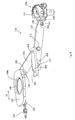
FIG. 1 is a schematic view of the cutting machine of the first embodiment according to the present invention; -
FIG. 2 is a schematic view of the worktable of the cutting machine which is assembled the supporting unit inFIG. 1 ; -
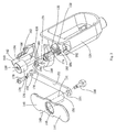
FIG. 3 is an exploded view of the saw blade clamp of the cutting machine inFIG. 1 ; -
FIG. 4 is a schematic view of the saw blade clamp of the cutting machine inFIG. 3 , wherein the saw blade clamp is clamped; -
FIG. 5 is a schematic view of the saw blade clamp of the cutting machine inFIG. 3 , wherein the saw blade clamp is released; -
FIG. 6 is a plan view of the saw blade clamp inFIG. 4 ; -
FIG. 7 is a plan view of the saw blade clamp inFIG. 5 ; -
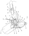
FIG. 8 is an exploded view of the saw blade clamp of the cutting machine of the second embodiment of the present invention; -
FIG. 9 is a schematic view of the saw blade clamp inFIG. 8 , wherein the saw blade clamp is released; -
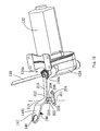
FIG. 10 is a side view of the saw blade clamp inFIG. 9 ; -
FIG. 11 is a side view of the saw blade clamp inFIG. 8 , wherein the saw blade clamp is clamped; -
FIG. 12 is a schematic view of the saw blade clamp of the cutting machine of the third embodiment according to the present invention; -
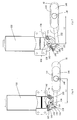
FIG. 13 is a side view of the saw blade clamp inFIG. 12 , wherein the saw blade clamp is released; -
FIG. 14 is a side view of the saw blade clamp inFIG. 12 , wherein the saw blade clamp is clamped; - Refering to the
figure 1-2 , a cutting machine 2 comprises aworktable 4, a supportingunit 10 for supporting theworktable 4, aguard assembly 6 disposed on theupper surface 22 of theworktable 4, apressing plate assembly 8 connecting to theguard assembly 6 and adjustably applying a certain pressure onto a workpiece, and acutting mechanism 12 disposed on thelower surface 24 of theworktable 4. - According to the use habits of operators, the left side of the
figure 1 is defined as the front portion of the cutting machine 2, while the right side is defined as the rear portion of the cutting machine 2. Theworktable 4 has theupper surface 22, thelower surface 24 andsidewalls upper surface 22 and thesidewalls worktable 4. Anopening 20 is formed on theworktable 4, positioned on the front portion of the cutting machine 2 and running through theupper surface 22 and thelower surface 24 from the top down. Asaw blade 130 passes through the opening 20 from the bottom up. Aworkpiece 19 is capable of being placed on theupper surface 22 of theworktable 4, moving along theupper surface 22 so as to be cut by thesaw blade 130. The opening 20 is square. A squareblade protecting plate 21 is capable of being embedded into the opening 20 for preventing dust front entering the cutting machine to a certain extent, and when thesaw blade 130 is broken, the protectingplate 21 is capable of being dismantled, so the operator takes out thesaw blade 130 from the cutting machine. Aslot 21a is formed in the middle of the protectingplate 21, and thesaw blade 130 passes through theslot 21a. - The
worktable 4 is also provided with a longitudinal T-slot 28 and a transverse T-slot 30. The longitudinal T-slot 28 extends from the front portion to the rear portion of theworktable 4. The transverse T-slot 30 is positioned on the front side of theopening 20 and intersected with the longitudinal T-slot 28 to divide theupper surface 22 of thewhole worktable 4 into four parts. The transverse T-slot 30 and the longitudinal T-slot 28 respectively extend fromsidewalls worktable 4 to reach theother sidewalls slot 28 and the transverse T-slot 30 are identical and thebottoms 29 thereof are also provided with several through-holes 31 disposed at intervals along the extension direction of the T-slot. - The
guard assembly 6 comprises abracket 56 detachably connected to the worktable, an extendingarm 58 vertical to the bracket, and an extendingguard 44 connected with the extendingarm 58, left andright guard plates guard body 34. Aguard clamping mechanism 48 with a clampingknob 50 adjustably fastens the extendingguard 44 on the extendingarm 58. Aguide wheel 70 is disposed below theguard body 34 for guiding the reciprocating motion of thesaw blade 130. Adust collecting hose 36 is positioned above theguard body 34 for connecting with a dust collector and collecting the dust generated during cutting. The left and right guard plates are connected with theguard body 34 via apin shaft 42. - A
pressing plate assembly 8 is positioned between theguard assembly 6 and theworktable 4 to realize the height adjustment of apressing plate 72 with respect to theworktable 4 by rotating an adjustingwrench 74. - The supporting
unit 10 comprises a base 82 with several supportinglegs 110 and abody 84 with supportingwalls drawer 88 is positioned at the front portion of the supportingunit 10 for collecting the dust. The front supportingwall 86b of thebody 84 is provided with a controllingpanel 112 for receiving amain switch 116 and aspeed adjusting switch 118 of the cutting machine 2. The supportingwalls base 10. In this embodiment, the supportingunit 10 has the supporting wall, however skilled persons in this field should understand that the worktable and the cutting mechanism are capable of being supported by several supporting legs. Therefore, the supporting unit in the present invention may also be the bracket consisting of supporting legs. The corresponding outer surface of the supporting unit is the outer walls of the supporting legs. - The
cutting mechanism 12 is fixed on thelower surface 24 of theworktable 4 and received in the supportingunit 10 and comprises amotor 120 generating rotation motion, areciprocating rod 126 driving thesaw blade 130 that passes through theopening 20 to move reciprocatedly, amotion conversion mechanism 132 converting the rotation driving of themotor 120 into the reciprocating motion of thereciprocating rod 126, and asaw blade clamp 14 operable to clamp and release thesaw blade 130. Thesaw blade clamp 14 comprises anoperating element 144 positioned on theworktable 4 or on the outer surface of the supportingunit 10. - The first embodiment of the
saw blade clamp 14 is further described in combination with the attached drawings 1-7. - The cutting machine 2 has a
cutting mechanism 12, wherein thecutting mechanism 12 comprises amotor 120, amotor housing 122 receiving themotor 120, and agearbox housing 124 connected with thehousing 122 and receiving themotion conversion mechanism 132. The rotation motion of themotor 120 is converted into the reciprocating motion of areciprocating rod 126 along areciprocating rod axis 128 by themotion conversion mechanism 132. - In this embodiment, the
saw blade clamp 14 comprises aclamp 134 connected to thereciprocating rod 126. Theclamp 134 comprises arotating sleeve 136 having aslot 138 for thesaw blade 130 passing through, and a clamping element (not shown in the figure) that is received in therotating sleeve 136 and clamps and releases thesaw blade 130 along with the rotation of therotating sleeve 136 with respect to thereciprocating rod axis 128. This kind of clamp is suitable for clamping the T-shaped saw blade, namely a saw blade with a protrusion at the tail, and the protrusion of the clamped saw blade is stopped by the end face of therotating sleeve 136 with theslot 138. The outer wall of therotating sleeve 136 extends outwards to form a clampingwrench 140, so an operator is able to turn the clampingwrench 140 to rotate around thereciprocating rod axis 128 so as to clamp and release thesaw blade 130. - In this embodiment, the
saw blade clamp 14 also comprises anoperating element 144 positioned on theupper surface 22 of theworktable 4. In other words, the outer surface of theworktable 4 in this embodiment refers to theupper surface 22 thereof. Of course, the position of the operating element in the present invention is not only limited to the outer surface of the worktable, and the operating element is also capable of being disposed on the sidewall of the worktable, especially the front wall, which helps the operator replace the saw blade conveniently. The skilled persons in this field should understand that the operating element is also capable of being disposed on the outer surface of the supportingunit 10, for example, the front supporting wall or left/right supporting wall. In case the supporting unit has no supporting wall or only has the supporting leg, the outer surface of the supporting unit is the outer wall of the supporting leg. The distance between the operating element and the blade clamp is usually smaller than or equal to the length of a single arm of a person. Therefore, the operator is able to touch the operating element comfortably and saves labor during the operation of replacing the saw blade. - The
saw blade clamp 14 comprises a clampingwrench 140 rotating around thereciprocating rod axis 128, and a linkage mechanism which is positioned between the operatingelement 144 and the clampingwrench 140 to force the operatingelement 144 to drive the clampingwrench 140 to rotate. - In this embodiment, the linkage mechanism comprises a connecting
plate 152 that is connected with theoperating element 144 and rotates around arotation axis 155 parallel to thereciprocating rod axis 128, and an actuating element that is connected with the connectingplate 152 and drives the clampingwrench 140 to move. - The
operating element 144 comprises a slidingplate 146 that extends longitudinally, anopening 148 disposed in the middle portion of the sliding plate and a connectingrod 150 that extends vertically with respect to the sliding plate. Theaxis 151 of the connecting rod is parallel to theaxis 149 of the opening and the two axes are disposed at an interval. In this embodiment, the sliding plate surface of theoperating element 144 is basically aligned with theupper surface 22 of theworktable 4, and the tabletop of theworktable 4 has no protruding structure to influence the movement of the workpiece thereon. Of course, the operating element may also be sunk into the upper surface of the worktable, but can be directly touched from the upper surface. Therefore, the operating element can be conveniently operated to replace the saw blade without influence on the movement of the workpiece. Meanwhile, the worktable has a groove for receiving the operating element, and correspondingly the surface of the groove composes the outer surface of the worktable. - The connecting
plate 152 comprises pin holes 154 disposed on two ends of the connectingplate 152. Theoperating element 144 is connected with the connectingplate 152 via thepin 156, the pin holes 154 and the connectingrod 150. - Preferably, the actuating element comprises a
rotating frame 158 positioned rotatably with thereciprocating rod 126. Therotating frame 158 comprises a C-shapedbase portion 160 and a pushingcolumn 162 which extends vertically with respect to thebase portion 160. One end of thebase portion 160 is a connectingshaft portion 172 with arotating shaft 174, and the pushingcolumn 162 is positioned at the other end of thebase portion 160. A connectinglug 168 is positioned between the two ends of thebase portion 160 and provided with ahole 170 for connecting with the connectingplate 152 via thepin 178. Preferably, the rotatingaxis 155 of the connectingplate 152 is parallel to therotating shaft 174 of the actuating element. Especially, the rotatingaxis 155 of the connectingplate 152 rotates around therotating shaft 174 of the actuating element. The connectingshaft portion 172 of therotating frame 158 is provided with a connectinghole 176, connecting with thegearbox housing 124 via thepin 179. - To ensure that the
rotating frame 158 is able to actuate the clampingwrench 140 no matter where thereciprocating rod 126 is positioned, the height of the pushingcolumn 162 is set to the more than the reciprocating travel of thereciprocating rod 126. Of course, the height of the pushingcolumn 162 is better equal to sum of the reciprocating travel of thereciprocating rod 126 and the axial length of theclaming wrench 140, so the pushingcolumn 162 is capable of contacting the clampingwrench 140 on the whole length of the clampingwrench 140 and ensures to reliably push theclamping wrench 140 and rotate therotating sleeve 136 of the clamp. - The pushing
column 162 has a biasingsurface 164, and after the assembly of thesaw blade clamp 14 is completed, the biasingsurface 164 is opposite to the biasingsurface 142 of the clampingwrench 140. During the reciprocating cutting motion of thesaw blade 130, the biasingsurface 164 and the biasingsurface 142 have no contact and keep a certain distance there-between. When thesaw blade 130 is required to be replaced, theoperating element 144 drives the connectingplate 152 to move so as to drive therotating frame 158 to rotate around therotating shaft 174. After therotating frame 158 rotates to a certain angle, the biasingsurface 164 contacts the biasingsurface 142, and then the pushingcolumn 162 is able to further push theclamping wrench 140 to rotate. To prevent the pushingcolumn 162 from failing in the process of pushing the clampingwrench 140 to rotate, the pushingcolumn 162 is provided with astop protrusion 166, so when the clampingwrench 140 is pressed against the pushingcolumn 162, thestop protrusion 166 prevents the biasingsurface 142 of the clampingwrench 140 from leaving the biasingsurface 164 of the pushingcolumn 162. - The
saw blade lamp 14 also comprises an elastic element forcing theoperating element 144 to move towards the clamping position. In this embodiment, thecutting mechanism 12 comprises agearbox housing 124. The elastic element is atorsion spring 180 disposed between the actuating element and the gearbox housing, forcing the actuating element to rotate towards the position where the saw blade is clamped. Specifically, the position, close to the receivinghole 125 of the reciprocating rod, of thegearbox housing 124 is provided with agroove 182 which extends along thereciprocating rod axis 128 and a stoppinggroove 184 which is protruded from the groove. Thegroove 182, the stoppinggroove 184 and the connectinghole 176 of the connectingrotation portion 172 of the stoppinggroove 184 together receive thetorsion spring 180. Therefore, one end of thetorsion spring 180 is clamped in the stoppinggroove 184, while the other end is clamped in the connectinghole 176. - In this embodiment, the
operating element 144 moves relative to theworktable 4. Theworktable 4 has a slidingchute 32, and theoperating element 144 comprises a slidingplate 146. The slidingplate 146 is operable to slide between the position where the saw blade is clamped and the position where the saw blade is released along the slidinggroove 32. The slidinggroove 32 is positioned at the front portion of theworktable 4 and on the right side of theopening 20, so the operator is able to replace the saw blade at a comfortable position. Theoperating element 144 also comprises anopening 148 formed on the slidingplate 146. Therefore, the operator is able to stretch their fingers into theopening 148 to move the slidingplate 146 in the direction away from thesaw blade 130. - The attached drawings 4-7 below illustrate the concrete operation process of the
saw blade clamp 14.Figure 4 andfigure 6 are schematic views of thesaw blade clamp 14 in the clamped state. In the clamped state, theoperating element 144 is located at the clamping position on the far left end of the slidinggroove 32. Under the action of thetorsion spring 180, therotating frame 158 separates the biasingsurface 164 of the pushingcolumn 162 from the biasingsurface 142 of the clampingwrench 140. At this time, the vertical distance from the openingaxis 149 of theoperating element 144 to thereciprocating rod axis 128 is L1, the protrusion of thesaw blade 130 is stopped by the end face of therotating sleeve 136 of the clamp, and the saw blade is clamped by the clamping element. When the saw blade is required to be replaced, the operator moves the slidingplate 146 rightwards along the direction of the arrow A1 in the figure to force the connectingplate 152 to move so as to drive therotating frame 158 to rotate around therotating shaft 174, and then the biasingsurface 164 of the pushingcolumn 162 is forced to contact the biasingsurface 142 of the clampingwrench 140; if continuously moves the slidingplate 146 to force the pushingcolumn 160 to push theclamping wrench 140 to the release position, the protrusion of thesaw blade 130 is aligned with theslot 138 on therotating sleeve 136 of the clamp, and then the operable is able to take out the saw blade with the other hand.Figure 5 andfigure 7 are schematic views of thesaw blade clamp 14 at the released state. At the released state, theoperating element 144 is located at the releasing position on the far right end of the slidinggroove 32. The vertical distance from the openingaxis 149 of theoperating element 144 to thereciprocating rod axis 128 is L2 which is more than L1. At this moment, if the operator releases the slidingplate 146, therotating frame 158 will automatically return to the clamped state under the action of thetorsion spring 180 and correspondingly drive the connectingplate 152 and theoperating element 144 to return to the clamping positions. - The second embodiment of the
saw blade clamp 14a is further described below in combination with the attached drawings 8-11. - In this embodiment, the
saw blade clamp 14a comprises aclamp 134a connected to thereciprocating rod 126. Theclamp 134a comprises aU-shaped clamping wrench 140a and a clamping element (not shown in the figure) which is operated by the clampingwrench 140a and moves along the inclined sliding groove on the clamping 135 to clamp and release thesaw blade 130. This kind of clamp is suitable for clamping T-shaped and U-shaped saw blades, which means no matter whether or not the tail of the saw blade has a protrusion the saw blade is capable of being clamped. The operator is able to pull the clampingwrench 140a to rotate with respect to the axis vertical to thereciprocating rod axis 128, so the clamping element is forced to clamp and release thesaw blade 130. - In this embodiment, the
operating element 144a is also disposed on theupper surface 22 of theworktable 4. - The
saw blade clamp 14a comprises a clampingwrench 140a rotating around the axis vertical to thereciprocating rod axis 128, and a linkage mechanism is disposed between the operatingelement 144a and the clampingwrench 140a, so theoperating element 144a is forced to drive the clampingwrench 140a to rotate so as to clamp and release the saw blade. - In this embodiment, the linkage mechanism comprises a connecting
plate 152 that is connected with theoperating element 144a and rotates around a rotation axis vertical to thereciprocating rod axis 128, and an actuating element that is connected with the connectingplate 152 and drives the clampingwrench 140a to move. - The
operating element 144a comprises a slidingplate 146 that extends longitudinally, anopening 148 disposed in the middle portion of the sliding plate, andlarge lugs 188 and asmall lug 190 which are positioned on the two ends of the slidingplate 146 and extend vertically with respect to the slidingplate 146. There are twolarge lugs 188, one end of the connectingplate 152 is capable of being inserted between the twolarge lugs 188 which are provided with holes matched with the pin holes 154 on the connectingplate 152, andoperating element 144a and the connectingplate 152 are connected via thepin 156. The hole axes 189 on thelarge lugs 188 are vertical to theopening axis 149. - Preferably, the actuating element comprises a
pressing pole 192 rotating with respect to the axis vertical to thereciprocating rod axis 128. Apivot hole 194 is disposed at one end of thepressing pole 192, apressing portion 198 is disposed on the other end, and apin hole 196 is disposed between the two ends. Thepivot hole 194 of thepressing pole 192 and thepin hole 210 of a fixingplate 202 are rotationally mounted on theworktable 4 via thepin 157. The fixingplate 202 has a fixingportion 204 and a connectingportion 208 which extends vertically with respect to the fixing portion. The fixingportion 204 is provided with two mountingholes 206 for stably connecting the fixinghole 202 and theworktable 4 or the supportingunit 10. Thepin hole 154 on the connectingplate 152 and thepin hole 196 in the middle portion of thepressing pole 192 are connected by thepin 212. Thepressing portion 198 of thepressing pole 192 has apressing surface 200 which is driven by the connectingplate 152 to rotate around therotating shaft 194 so as to move the clampingwrench 140a. - The
pressing pole 192 is able to move between the releasing position as shown infigure 10 and the clamping position as shown infigure 11 , and the rotating angle isθ. Thereciprocating rod 126 is at different reciprocating position in different cutting process. The reciprocating travel of thereciprocating rod 126 is H. The distance from therotating shaft 194 of thepressing pole 192 to thepressing surface 200 of thepressing portion 198 is D. To ensure that thepressing pole 192 is able to actuate the clampingwrench 140a no matter where thereciprocating rod 126 is positioned, the product uses the distance from therotating shaft 194 of thepressing pole 192 to thepressing surface 200 of thepressing portion 198 by multiplying the sine of the angle about thepressing pole 192 rotating around thepivot hole 194 which is larger than the reciprocating travel of thereciprocating rod 126, which means D*sinθ>H. Of course, the product uses the distance from therotating shaft 194 of thepressing pole 192 to thepressing surface 200 of thepressing portion 198 multiplies the sine of the angle about thepressing pole 192 rotating around thepivot hole 194 is which larger than the sum of the reciprocating travel of thereciprocating rod 126 and the width of the pressing surface of the clampingwrench 140a, so thepressing pole 192 is able to contact the clampingwrench 140a on the whole pressing surface width of the clamping wrench to ensure that the clampingwrench 140a is reliably clamped. - The
pressing pole 192 has apressing surface 200, and after the assembly of thesaw blade clamp 14a is completed, thepressing surface 200 is face to thepressing surface 141 of the clampingwrench 140a. During the reciprocating cutting motion of thesaw blade 130, thepressing surfaces saw blade 130 is required to be replaced, theoperating element 144a drives the connectingplate 152 to move so as to drive therotating frame 192 to rotate around the rotatingaxis 211. After therotating frame 192 rotates to a certain angle, thepressing surfaces pressing pole 192 is able to further force the clampingwrench 140a to rotate. - The
saw blade lamp 14a also comprises an elastic element forcing theoperating element 144a to move towards the clamping position. In this embodiment, the elastic element is atension spring 186 disposed between the operatingelement 144a and theworktable 4, forcing theoperating element 144a to move towards the position where the saw blade is clamped. Specifically, theoperating element 144a is provided with asmall lug 190 with a hole. One end of thetension spring 186 is hooked into the hole of thesmall lug 190, and the other end is hooked to theworktable 4. - In this embodiment, the
operating element 144a translates relative to theworktable 4. Theworktable 4 is provided with a slidinggroove 32, and theoperating element 144 comprises the slidingplate 146. The slidingplate 146 is able to slide between the position where the saw blade is clamped and the position where the saw blade is released along the slidinggroove 32. The slidinggroove 32 is positioned at the front portion of theworktable 4 and on the right side of theopening 20, so the operator is able to replace the saw blade at a comfortable position. Theoperating element 144 also comprises anopening 148 formed on the slidingplate 146. Therefore, the operator is able to stretch their fingers into theopening 148 to move the slidingplate 146 in the direction away from thesaw blade 130. - The attached drawings 10-11 below illustrate the concrete operation process of the
saw blade clamp 14a.Figure 11 is a schematic view of the saw blade clamp 14a at the clamped state. At the clamped state, theoperating element 144a is located at the clamped position on the far left end of the slidinggroove 32. Under the action of thetension spring 186, thepressing surface 200 of thepressing pole 192 and thepressing surface 141 of theclaming wrench 140a are partitioned. At this moment, the vertical distance from the openingaxis 149 of theoperating element 144a to thereciprocating rod axis 128 is L3, and the saw blade is clamped by the clamping element. When the saw blade is required to be replaced, the operator should move the slidingplate 146 rightwards along the direction of the arrow A2 in the figure to force the connectingplate 152 to move so as to drive thepressing frame 192 to rotate around the rotatingaxis 211, and then thepressing surface 200 of thepressing pole 192 is forced to contact thepressing surface 141 of the clampingwrench 140a; if it continuously moves the slidingplate 146, thepressing pole 192 pushes the clampingwrench 140a to the release position, and then the operator is able to take out the saw blade with the other hand.Figure 10 is a schematic view of the saw blade clamp 14a at the released state. At the released state, theoperating element 144a is located at the releasing position on the far right end of the slidinggroove 32. The vertical distance from the openingaxis 149 of theoperating element 144a to thereciprocating rod axis 128 is L4 which is shorter than L3. At this moment, the operator releases the slidingplate 146, theoperating element 144a will automatically return to the clamped state under the action of thetension spring 186 and correspondingly drive the connectingplate 152 and thepressing plate 192 to return to the clamping positions. Therefore, the clampingwrench 140a of the clamp will also return to the clamping position. - The attached drawings 12-14 illustrate the third embodiment of the
saw blade clamp 14b. - In this embodiment, the units and parts of the
saw blade clamp 14b, identical with those in the second embodiment, adopt the same mark numbers. Herein, the following is the detailed description of the differences between this embodiment and the above embodiment. - In this embodiment, the
operating element 144b is positioned on the upper surface of theworktable 4. Theoperating element 144b rotates with respect to theworktable 4 to clamp and release the saw blade. - The
saw blade clamp 14b comprises the clampingwrench 140a rotating around the axis vertical to thereciprocating rod axis 128, and an actuating element is disposed between the operatingelement 144b and the clampingwrench 140a. - The
worktable 4 is provided with the receivinggroove 33 in which theoperating element 144b is received. Theoperating element 144b comprises aflat plate body 147 and anopening 148 formed at one end of theflat plate body 147. The middle portion of theflat plate body 147 extends vertically to form apull ring 214. In this embodiment, the actuating element is thepressing plate 216. One end of thepressing plate 216 faces the clampingwrench 140a, while the other end is stably connected with the end of theoperating element 144b via therotating connection portion 215. Preferably, theoperating element 144b, therotating connection portion 215 and thepressing plate 216 are integrally molded. The skilled persons in this field should understand that thepressing plate 216 and theoperating element 144b have other fixed connections, such as welding, riveting, etc. Therotating connection portion 215 has a pivot hole connected to the fixingplate 202 via thepin 212. Therefore, theoperating element 144b and thepressing plate 216 rotates around the samerotating axis 211. - The
pressing pole 216 is able to rotate between the releasing position as shown infigure 13 and the clamping position as shown infigure 14 , and the rotating angle is α. Thereciprocating rod 126 is at different reciprocating positions in different cutting processes. The reciprocating travel of thereciprocating rod 126 is H. The distance from the pivot hole of thepressing plate 216 to thepressing surface 213 is L. To ensure that thepressing pole 216 is able to actuate the clampingwrench 140a no matter where thereciprocating rod 126 is positioned, the product uses the distance from the pivot hole of thepressing pole 216 to the pressing surface and multiplies the sine of the angle about thepressing plate 216 rotating around the rotatingaxis 211 which is larger than the reciprocating travel of thereciprocating rod 126, which means that L*sinα〉 H. Of course, the product uses the distance from the pivot hole of thepressing plate 216 to thepressing surface 213 and multiplies the sine of the angle about thepressing plate 216 rotating around the rotatingaxis 211 which is larger than the sum of the reciprocating travel of thereciprocating rod 126 and the width of thepressing surface 213 of the clampingwrench 140a, so thepressing plate 216 is able to contact the clampingwrench 140a on the wholepressing surface 213 width of the clamping wrench to ensure that the clampingwrench 140a is reliably clamped. - One end of the elastic element, namely the
tension spring 186, is hooked with thepull ring 214 of theoperating element 144b, and the other end is connected with theworktable 4 or the supportingunit 10, so the operatingelement 144b moves towards the clamping position. - The operating element is also capable of being disposed on the supporting unit. Specifically, the operating element is disposed on the base at the bottom portion of the supporting unit. Furthermore, the operating element is disposed at the front of the base, namely the side that the operator directly faces during operation.
- The skilled persons in this field should understand that the concrete structures of the operating element, etc. in the present invention may have variations. For example, the clamp has many structures in the prior art, capable of being equivalently replaced by the clamp structure disclosed in the present invention. For example, the elastic element has two forms, namely the torsion spring and the tension spring, in the present invention, but the skilled persons in this field should know that other kinds of springs, such as the compression spring and the leaf spring, or other kinds of elastic elements, such as the elastic rubber piece, etc., all can be used as the elastic element in the present invention. Therefore, any variation and replacement based on the present invention shall be within the protection scope of the present invention.
Claims (22)
- A cutting machine (2) comprising:a worktable (4) including an opening (20) and an upper surface (22) for supporting a workpiece (19);a supporting unit (10) for supporting the worktable, wherein the worktable and supporting unit have an external surface;a cutting mechanism (12) mounted on a lower surface (24) of the worktable and contained within the supporting unit comprising: a motor (120) for outputting a rotation motion; a reciprocating rod (126) driving a saw blade (130) moving reciprocately through the opening; a motion conversion mechanism (132) converting the rotation motion of the motor into a reciprocating motion of the reciprocating rod; and a saw blade clamp (14, 14a, 14b) for clamping and releasing the saw blade,characterized in that the saw blade clamp comprises an operating element (144, 144a, 144b) for operating the saw blade clamp which is disposed on the external surface of the worktable or the supporting unit.
- The cutting machine (2) of claim 1, wherein the operating element (144, 144a, 144b) is disposed on the upper surface (22) of the worktable (4).
- The cutting machine (2) of claim 2, wherein the saw blade clamp (14) comprises a clamping wrench (140) rotating around a reciprocating rod axis (128) of the reciprocating rod (126), a linkage mechanism is disposed between the operating element (144) and the clamping wrench, and thus the operating element is operable to drive the clamping wrench rotating.
- The cutting machine (2) of claim 3, wherein the linkage mechanism comprises a connecting plate (152) connected to the operating element (144) and rotating around a rotating axis (155) which is parallel to the reciprocating rod axis (128), and an actuating element being connected to the connecting plate and driving the clamping wrench (140) moving.
- The cutting machine (2) of claim 4, wherein the rotating axis (155) of the connecting plate (152) is parallel to the rotating axis of the actuating element.
- The cutting machine (2) of claim 5, wherein the rotating axis (155) of the connecting plate (152) rotates around the rotating axis of the actuating element.
- The cutting machine (2) of claim 6, wherein the actuating element comprises a rotating frame (158) being disposed rotatablely with respect to the reciprocating rod (126), the rotating frame comprises a C-shape base portion (160), a connecting shaft (172) is disposed at one end of the base portion, a pushing column (162) which extends vertically is disposed at the other end of the base portion, and a connecting lug (168) is disposed between the two ends of the base portion.
- The cutting machine (2) of claim 7, wherein the height of the pushing column (162) is larger than a reciprocating travel of the reciprocating rod (126).
- The cutting machine (2) of claim 8, wherein a stop protrusion (166) is disposed on the pushing column (162), when the clamping wrench (140) contacts with a biasing surface (164) of the pushing column, the stop protrusion would prevent the clamping wrench leaving from the biasing surface.
- The cutting machine (2) of claim 2, wherein the saw blade clamp (14, 14a) further comprises an elastic element (180, 186) biases the operating element (144, 144a) moving towards a clamping position at where being clamped the saw blade (130).
- The cutting machine (2) of claim 10, wherein the elastic element is a tension spring (186) which is disposed between the worktable (4) and the operating element (144a), the tension spring is tensible along the moving direction of the operating element.
- The cutting machine (2) of claim 10, wherein the saw blade clamp (14) comprises a clamping wrench (140) rotating around a reciprocating rod axis (128) of the reciprocating rod (126), an actuating element being connected to the operating element (144) and driving the clamping wrench moving, the cutting mechanism (12) comprises a gearbox housing (124), the elastic element is a torsion spring (180) which is disposed between the actuating element and the gearbox housing, the torsion spring biases the actuating element rotating towards a clamping position at where being clamped the saw blade (130).
- The cutting machine (2) of claim 2, wherein the operating element (144, 144a) is translationally movable to the worktable (4).
- The cutting machine (2) of claim 13, wherein a sliding groove (32) is disposed on the worktable (4), the operating element (144, 144a) comprises a sliding plate (146), the sliding plate is operable moving along the sliding groove between a releasing position where the saw blade (130) is released and a clamping position where the saw blade is clamped.
- The cutting machine (2) of claim 14, wherein the operating element (144, 144a) comprises an opening (148) is disposed on the sliding plate (146).
- The cutting machine (2) of claim 2, wherein the saw blade clamp (130) comprises a clamping wrench (140a) rotating around a rotating axis which is vertical to the reciprocating rod axis (128) of the reciprocating rod, and a linkage mechanism being disposed between the operating element (144a) and the clamping wrench.
- The cutting machine (2) of claim 16, wherein the linkage mechanism comprises a connecting plate (152) connected to the operating element (144a) and rotating around a rotating axis which is vertical to the reciprocating rod axis (128), and an actuating element connected to the connecting plate and driving the clamping wrench (140a) moving.
- The cutting machine (2) of claim 17, wherein the actuating element comprises a pressing pole (192), a pivot hole (194) is disposed at one end of the pressing pole, the pressing pole is rotatablely mounted on the worktable (4) or the base (82), a pressing portion (198) is disposed at the other end of the pressing pole, the connecting plate (152) connects to the middle portion of the pressing pole by a pin (157), the pressing portion is driven by the connecting plate and rotating around the pivot hole for moving the clamping wrench (140a).
- The cutting machine (2) of claim 18, wherein a product which a distance from the center of the pivot hole (194) to the pressing surface (200) of the pressing portion (198) multiplies a sine of a rotating angle that the pressing pole (192) rotates around the pivot hole is larger than a reciprocating travel of the reciprocating rod (126).
- The cutting machine (2) of claim 2, wherein the operating element (144b) is rotatable relative to the worktable (4).
- The cutting machine (2) of claim 20, wherein the saw blade clamp (14b) comprises a clamping wrench (140a) rotating around a rotating axis which is vertical to the reciprocating rod axis (128) of the reciprocating rod, an actuating element is pivotally disposed between the operating element (144b) and the clamping wrench.
- The cutting machine (2) of claim 21, wherein the operating element (144b) and the actuating element are rotatable around a same pivot shaft.
Applications Claiming Priority (4)
| Application Number | Priority Date | Filing Date | Title |
|---|---|---|---|
| CN200910163870XA CN101987381B (en) | 2009-08-07 | 2009-08-07 | Cutting machine |
| CN2009101736168A CN102000880B (en) | 2009-09-03 | 2009-09-03 | Cutting machine |
| CN 200910178066 CN102019464B (en) | 2009-09-22 | 2009-09-22 | Cutting machine |
| PCT/CN2010/075798 WO2011015158A1 (en) | 2009-08-07 | 2010-08-09 | Cutting machine |
Publications (3)
| Publication Number | Publication Date |
|---|---|
| EP2463048A1 EP2463048A1 (en) | 2012-06-13 |
| EP2463048A4 EP2463048A4 (en) | 2014-04-09 |
| EP2463048B1 true EP2463048B1 (en) | 2016-03-30 |
Family
ID=43543947
Family Applications (1)
| Application Number | Title | Priority Date | Filing Date |
|---|---|---|---|
| EP10806062.5A Not-in-force EP2463048B1 (en) | 2009-08-07 | 2010-08-09 | Cutting machine |
Country Status (3)
| Country | Link |
|---|---|
| US (1) | US9067267B2 (en) |
| EP (1) | EP2463048B1 (en) |
| WO (1) | WO2011015158A1 (en) |
Families Citing this family (10)
| Publication number | Priority date | Publication date | Assignee | Title |
|---|---|---|---|---|
| WO2011015160A1 (en) * | 2009-08-07 | 2011-02-10 | 苏州宝时得电动工具有限公司 | Cutting machine |
| CN104227783A (en) * | 2013-06-09 | 2014-12-24 | 宋忆宁 | Paper shredding device convenient to use |
| CN106041694B (en) * | 2016-07-26 | 2018-07-20 | 锐奇控股股份有限公司 | A kind of sand paper holding structure of sander |
| CN107738296A (en) * | 2017-11-23 | 2018-02-27 | 蚌埠威尔特滤清器有限公司 | A kind of corner cut equipment for air-conditioning filter cleaner |
| CN108901255A (en) * | 2018-07-17 | 2018-11-30 | 合肥霞康电子商务有限公司 | A kind of seedlings nursing plate pressure cave device |
| CN110230183B (en) * | 2019-07-01 | 2021-11-02 | 福建七匹狼实业股份有限公司 | Garment cutting system |
| CN112045257A (en) * | 2020-09-02 | 2020-12-08 | 中国十七冶集团有限公司 | High-rise building jacking die carrier construction is with preventing that work piece rocks cutting process device |
| US11826840B1 (en) * | 2022-07-21 | 2023-11-28 | Ronald Dennis Autrey | Scroll saw with movable arm |
| CN115446996B (en) * | 2022-07-21 | 2023-08-01 | 湖北国通领驭建设集团有限公司 | Reinforced concrete cutting equipment for hydropower installation of factory building |
| KR102788024B1 (en) * | 2023-11-20 | 2025-03-28 | 권영달 | Glass wool mat cutting machine that is easy to move and carry |
Citations (1)
| Publication number | Priority date | Publication date | Assignee | Title |
|---|---|---|---|---|
| US20050183559A1 (en) * | 2004-02-19 | 2005-08-25 | Rue Jerry R. | Reciprocating table saw |
Family Cites Families (12)
| Publication number | Priority date | Publication date | Assignee | Title |
|---|---|---|---|---|
| US3561185A (en) | 1968-02-12 | 1971-02-09 | Dyckerhoff & Widmann Ag | Armoring and stressing rod for concrete |
| US4186784A (en) | 1977-07-21 | 1980-02-05 | Atlantic Container Corporation | Tool table construction |
| GB2076737B (en) | 1980-05-27 | 1984-07-11 | Hollins Fred | Jig saw |
| US6267038B1 (en) | 1998-02-06 | 2001-07-31 | Black & Decker Inc. | Variable cut scroll saw |
| DE19925749A1 (en) | 1999-06-05 | 2000-12-07 | Bosch Gmbh Robert | Handheld jigsaw |
| US6986370B1 (en) * | 2000-02-01 | 2006-01-17 | Home Depot U.S.A., Inc. | Table saw |
| CN200970657Y (en) | 2006-05-25 | 2007-11-07 | 南京德朔实业有限公司 | Saw blade fastener |
| DE102006062000A1 (en) | 2006-12-29 | 2008-07-03 | Robert Bosch Gmbh | Stationary, motor operated underfloor saw e.g. pendular hack saw, has saw blade projected upward by table surface, and drive unit comprising motor and connected with saw blade to saw unit, where saw is designed as hack saw |
| DE102007052432A1 (en) | 2007-11-02 | 2009-05-07 | Seefluth, Christian | Stationary motor-driven compass saw comprises a saw blade arranged at a right angle to a horizontal working surface and having a mechanical guide formed by rollers or a sliding body in the region of a non-driven end |
| CN201227702Y (en) | 2008-07-25 | 2009-04-29 | 苏州宝时得电动工具有限公司 | Reciprocating saw |
| CN201471000U (en) | 2009-08-07 | 2010-05-19 | 苏州宝时得电动工具有限公司 | Cutting machine |
| CN201483084U (en) | 2009-09-03 | 2010-05-26 | 苏州宝时得电动工具有限公司 | Cutting machine |
-
2010
- 2010-08-09 US US13/389,425 patent/US9067267B2/en active Active
- 2010-08-09 WO PCT/CN2010/075798 patent/WO2011015158A1/en not_active Ceased
- 2010-08-09 EP EP10806062.5A patent/EP2463048B1/en not_active Not-in-force
Patent Citations (1)
| Publication number | Priority date | Publication date | Assignee | Title |
|---|---|---|---|---|
| US20050183559A1 (en) * | 2004-02-19 | 2005-08-25 | Rue Jerry R. | Reciprocating table saw |
Also Published As
| Publication number | Publication date |
|---|---|
| WO2011015158A1 (en) | 2011-02-10 |
| US9067267B2 (en) | 2015-06-30 |
| EP2463048A4 (en) | 2014-04-09 |
| US20120132050A1 (en) | 2012-05-31 |
| EP2463048A1 (en) | 2012-06-13 |
Similar Documents
| Publication | Publication Date | Title |
|---|---|---|
| US9067267B2 (en) | Cutting machine with blade clamp | |
| US6241594B1 (en) | Hand machine tool adjustable front handle | |
| US20080047411A1 (en) | Saw | |
| US9216485B2 (en) | Quick clamping device adapted for worktable | |
| EP2777879B1 (en) | Clamp | |
| CN201471000U (en) | Cutting machine | |
| CN103418836B (en) | A kind of electric hand tool with rail plate | |
| CN102114555A (en) | Electric tool | |
| CN110744135B (en) | Handheld band saw | |
| GB2446690A (en) | A Miter Saw | |
| US20050060896A1 (en) | Clamping apparatus for a tool component and an improved scrolling mechanism | |
| CA2453205A1 (en) | Clamping arrangement for receiving a saw blade in multiple orientations | |
| US8752644B2 (en) | Electric tool, particularly a saw | |
| US7168181B2 (en) | Hand tool apparatus and method | |
| US20160322183A1 (en) | Device switch for power tools including a switch locking mechanism | |
| US20070180711A1 (en) | Jigsaw actuation mechanism for imparting scrolling, orbital and reciprocating movement | |
| CN101987381B (en) | Cutting machine | |
| CN110744134B (en) | Handheld Band Saw | |
| CN208556769U (en) | A kind of fixture for processing aluminum profile dual-face milling machines | |
| GB2441869A (en) | Band saw machine with actuating shaft for replacing saw blade | |
| WO2012146214A1 (en) | Oblique cutting saw | |
| CN102019464B (en) | Cutting machine | |
| CN201543909U (en) | Cutting machine | |
| CN110744504B (en) | Handheld Power Tools | |
| CN100592951C (en) | Base plate of hand-held saw in straight reciprocating motion and the hand-held saw in straight reciprocating motion |
Legal Events
| Date | Code | Title | Description |
|---|---|---|---|
| PUAI | Public reference made under article 153(3) epc to a published international application that has entered the european phase |
Free format text: ORIGINAL CODE: 0009012 |
|
| 17P | Request for examination filed |
Effective date: 20120207 |
|
| AK | Designated contracting states |
Kind code of ref document: A1 Designated state(s): AL AT BE BG CH CY CZ DE DK EE ES FI FR GB GR HR HU IE IS IT LI LT LU LV MC MK MT NL NO PL PT RO SE SI SK SM TR |
|
| DAX | Request for extension of the european patent (deleted) | ||
| A4 | Supplementary search report drawn up and despatched |
Effective date: 20140311 |
|
| RIC1 | Information provided on ipc code assigned before grant |
Ipc: B23D 51/02 20060101ALI20140305BHEP Ipc: B27B 19/04 20060101ALI20140305BHEP Ipc: B23D 51/08 20060101AFI20140305BHEP |
|
| 17Q | First examination report despatched |
Effective date: 20141009 |
|
| GRAP | Despatch of communication of intention to grant a patent |
Free format text: ORIGINAL CODE: EPIDOSNIGR1 |
|
| INTG | Intention to grant announced |
Effective date: 20150930 |
|
| GRAS | Grant fee paid |
Free format text: ORIGINAL CODE: EPIDOSNIGR3 |
|
| GRAA | (expected) grant |
Free format text: ORIGINAL CODE: 0009210 |
|
| AK | Designated contracting states |
Kind code of ref document: B1 Designated state(s): AL AT BE BG CH CY CZ DE DK EE ES FI FR GB GR HR HU IE IS IT LI LT LU LV MC MK MT NL NO PL PT RO SE SI SK SM TR |
|
| REG | Reference to a national code |
Ref country code: GB Ref legal event code: FG4D |
|
| REG | Reference to a national code |
Ref country code: CH Ref legal event code: EP |
|
| REG | Reference to a national code |
Ref country code: AT Ref legal event code: REF Ref document number: 784806 Country of ref document: AT Kind code of ref document: T Effective date: 20160415 |
|
| REG | Reference to a national code |
Ref country code: IE Ref legal event code: FG4D |
|
| REG | Reference to a national code |
Ref country code: DE Ref legal event code: R096 Ref document number: 602010031873 Country of ref document: DE |
|
| REG | Reference to a national code |
Ref country code: LT Ref legal event code: MG4D |
|
| PG25 | Lapsed in a contracting state [announced via postgrant information from national office to epo] |
Ref country code: FI Free format text: LAPSE BECAUSE OF FAILURE TO SUBMIT A TRANSLATION OF THE DESCRIPTION OR TO PAY THE FEE WITHIN THE PRESCRIBED TIME-LIMIT Effective date: 20160330 Ref country code: HR Free format text: LAPSE BECAUSE OF FAILURE TO SUBMIT A TRANSLATION OF THE DESCRIPTION OR TO PAY THE FEE WITHIN THE PRESCRIBED TIME-LIMIT Effective date: 20160330 Ref country code: GR Free format text: LAPSE BECAUSE OF FAILURE TO SUBMIT A TRANSLATION OF THE DESCRIPTION OR TO PAY THE FEE WITHIN THE PRESCRIBED TIME-LIMIT Effective date: 20160701 Ref country code: NO Free format text: LAPSE BECAUSE OF FAILURE TO SUBMIT A TRANSLATION OF THE DESCRIPTION OR TO PAY THE FEE WITHIN THE PRESCRIBED TIME-LIMIT Effective date: 20160630 |
|
| REG | Reference to a national code |
Ref country code: NL Ref legal event code: MP Effective date: 20160330 |
|
| REG | Reference to a national code |
Ref country code: AT Ref legal event code: MK05 Ref document number: 784806 Country of ref document: AT Kind code of ref document: T Effective date: 20160330 |
|
| REG | Reference to a national code |
Ref country code: FR Ref legal event code: PLFP Year of fee payment: 7 |
|
| PG25 | Lapsed in a contracting state [announced via postgrant information from national office to epo] |
Ref country code: SE Free format text: LAPSE BECAUSE OF FAILURE TO SUBMIT A TRANSLATION OF THE DESCRIPTION OR TO PAY THE FEE WITHIN THE PRESCRIBED TIME-LIMIT Effective date: 20160330 Ref country code: LV Free format text: LAPSE BECAUSE OF FAILURE TO SUBMIT A TRANSLATION OF THE DESCRIPTION OR TO PAY THE FEE WITHIN THE PRESCRIBED TIME-LIMIT Effective date: 20160330 Ref country code: LT Free format text: LAPSE BECAUSE OF FAILURE TO SUBMIT A TRANSLATION OF THE DESCRIPTION OR TO PAY THE FEE WITHIN THE PRESCRIBED TIME-LIMIT Effective date: 20160330 |
|
| PG25 | Lapsed in a contracting state [announced via postgrant information from national office to epo] |
Ref country code: NL Free format text: LAPSE BECAUSE OF FAILURE TO SUBMIT A TRANSLATION OF THE DESCRIPTION OR TO PAY THE FEE WITHIN THE PRESCRIBED TIME-LIMIT Effective date: 20160330 |
|
| PG25 | Lapsed in a contracting state [announced via postgrant information from national office to epo] |
Ref country code: EE Free format text: LAPSE BECAUSE OF FAILURE TO SUBMIT A TRANSLATION OF THE DESCRIPTION OR TO PAY THE FEE WITHIN THE PRESCRIBED TIME-LIMIT Effective date: 20160330 Ref country code: PL Free format text: LAPSE BECAUSE OF FAILURE TO SUBMIT A TRANSLATION OF THE DESCRIPTION OR TO PAY THE FEE WITHIN THE PRESCRIBED TIME-LIMIT Effective date: 20160330 Ref country code: IS Free format text: LAPSE BECAUSE OF FAILURE TO SUBMIT A TRANSLATION OF THE DESCRIPTION OR TO PAY THE FEE WITHIN THE PRESCRIBED TIME-LIMIT Effective date: 20160730 |
|
| PG25 | Lapsed in a contracting state [announced via postgrant information from national office to epo] |
Ref country code: PT Free format text: LAPSE BECAUSE OF FAILURE TO SUBMIT A TRANSLATION OF THE DESCRIPTION OR TO PAY THE FEE WITHIN THE PRESCRIBED TIME-LIMIT Effective date: 20160801 Ref country code: SM Free format text: LAPSE BECAUSE OF FAILURE TO SUBMIT A TRANSLATION OF THE DESCRIPTION OR TO PAY THE FEE WITHIN THE PRESCRIBED TIME-LIMIT Effective date: 20160330 Ref country code: RO Free format text: LAPSE BECAUSE OF FAILURE TO SUBMIT A TRANSLATION OF THE DESCRIPTION OR TO PAY THE FEE WITHIN THE PRESCRIBED TIME-LIMIT Effective date: 20160330 Ref country code: AT Free format text: LAPSE BECAUSE OF FAILURE TO SUBMIT A TRANSLATION OF THE DESCRIPTION OR TO PAY THE FEE WITHIN THE PRESCRIBED TIME-LIMIT Effective date: 20160330 Ref country code: SK Free format text: LAPSE BECAUSE OF FAILURE TO SUBMIT A TRANSLATION OF THE DESCRIPTION OR TO PAY THE FEE WITHIN THE PRESCRIBED TIME-LIMIT Effective date: 20160330 Ref country code: ES Free format text: LAPSE BECAUSE OF FAILURE TO SUBMIT A TRANSLATION OF THE DESCRIPTION OR TO PAY THE FEE WITHIN THE PRESCRIBED TIME-LIMIT Effective date: 20160330 Ref country code: CZ Free format text: LAPSE BECAUSE OF FAILURE TO SUBMIT A TRANSLATION OF THE DESCRIPTION OR TO PAY THE FEE WITHIN THE PRESCRIBED TIME-LIMIT Effective date: 20160330 |
|
| PG25 | Lapsed in a contracting state [announced via postgrant information from national office to epo] |
Ref country code: BE Free format text: LAPSE BECAUSE OF FAILURE TO SUBMIT A TRANSLATION OF THE DESCRIPTION OR TO PAY THE FEE WITHIN THE PRESCRIBED TIME-LIMIT Effective date: 20160330 Ref country code: IT Free format text: LAPSE BECAUSE OF FAILURE TO SUBMIT A TRANSLATION OF THE DESCRIPTION OR TO PAY THE FEE WITHIN THE PRESCRIBED TIME-LIMIT Effective date: 20160330 |
|
| REG | Reference to a national code |
Ref country code: DE Ref legal event code: R097 Ref document number: 602010031873 Country of ref document: DE |
|
| PG25 | Lapsed in a contracting state [announced via postgrant information from national office to epo] |
Ref country code: DK Free format text: LAPSE BECAUSE OF FAILURE TO SUBMIT A TRANSLATION OF THE DESCRIPTION OR TO PAY THE FEE WITHIN THE PRESCRIBED TIME-LIMIT Effective date: 20160330 |
|
| PLBE | No opposition filed within time limit |
Free format text: ORIGINAL CODE: 0009261 |
|
| STAA | Information on the status of an ep patent application or granted ep patent |
Free format text: STATUS: NO OPPOSITION FILED WITHIN TIME LIMIT |
|
| 26N | No opposition filed |
Effective date: 20170103 |
|
| PG25 | Lapsed in a contracting state [announced via postgrant information from national office to epo] |
Ref country code: MC Free format text: LAPSE BECAUSE OF FAILURE TO SUBMIT A TRANSLATION OF THE DESCRIPTION OR TO PAY THE FEE WITHIN THE PRESCRIBED TIME-LIMIT Effective date: 20160330 |
|
| REG | Reference to a national code |
Ref country code: CH Ref legal event code: PL |
|
| PG25 | Lapsed in a contracting state [announced via postgrant information from national office to epo] |
Ref country code: LI Free format text: LAPSE BECAUSE OF NON-PAYMENT OF DUE FEES Effective date: 20160831 Ref country code: CH Free format text: LAPSE BECAUSE OF NON-PAYMENT OF DUE FEES Effective date: 20160831 |
|
| PG25 | Lapsed in a contracting state [announced via postgrant information from national office to epo] |
Ref country code: SI Free format text: LAPSE BECAUSE OF FAILURE TO SUBMIT A TRANSLATION OF THE DESCRIPTION OR TO PAY THE FEE WITHIN THE PRESCRIBED TIME-LIMIT Effective date: 20160330 |
|
| REG | Reference to a national code |
Ref country code: IE Ref legal event code: MM4A |
|
| PG25 | Lapsed in a contracting state [announced via postgrant information from national office to epo] |
Ref country code: IE Free format text: LAPSE BECAUSE OF NON-PAYMENT OF DUE FEES Effective date: 20160809 |
|
| REG | Reference to a national code |
Ref country code: FR Ref legal event code: PLFP Year of fee payment: 8 |
|
| PG25 | Lapsed in a contracting state [announced via postgrant information from national office to epo] |
Ref country code: LU Free format text: LAPSE BECAUSE OF NON-PAYMENT OF DUE FEES Effective date: 20160809 |
|
| PGFP | Annual fee paid to national office [announced via postgrant information from national office to epo] |
Ref country code: GB Payment date: 20170809 Year of fee payment: 8 Ref country code: DE Payment date: 20170822 Year of fee payment: 8 Ref country code: FR Payment date: 20170822 Year of fee payment: 8 |
|
| PG25 | Lapsed in a contracting state [announced via postgrant information from national office to epo] |
Ref country code: CY Free format text: LAPSE BECAUSE OF FAILURE TO SUBMIT A TRANSLATION OF THE DESCRIPTION OR TO PAY THE FEE WITHIN THE PRESCRIBED TIME-LIMIT Effective date: 20160330 Ref country code: HU Free format text: LAPSE BECAUSE OF FAILURE TO SUBMIT A TRANSLATION OF THE DESCRIPTION OR TO PAY THE FEE WITHIN THE PRESCRIBED TIME-LIMIT; INVALID AB INITIO Effective date: 20100809 |
|
| PG25 | Lapsed in a contracting state [announced via postgrant information from national office to epo] |
Ref country code: MK Free format text: LAPSE BECAUSE OF FAILURE TO SUBMIT A TRANSLATION OF THE DESCRIPTION OR TO PAY THE FEE WITHIN THE PRESCRIBED TIME-LIMIT Effective date: 20160330 Ref country code: MT Free format text: LAPSE BECAUSE OF NON-PAYMENT OF DUE FEES Effective date: 20160831 Ref country code: TR Free format text: LAPSE BECAUSE OF FAILURE TO SUBMIT A TRANSLATION OF THE DESCRIPTION OR TO PAY THE FEE WITHIN THE PRESCRIBED TIME-LIMIT Effective date: 20160330 |
|
| PG25 | Lapsed in a contracting state [announced via postgrant information from national office to epo] |
Ref country code: BG Free format text: LAPSE BECAUSE OF FAILURE TO SUBMIT A TRANSLATION OF THE DESCRIPTION OR TO PAY THE FEE WITHIN THE PRESCRIBED TIME-LIMIT Effective date: 20160330 |
|
| PG25 | Lapsed in a contracting state [announced via postgrant information from national office to epo] |
Ref country code: AL Free format text: LAPSE BECAUSE OF FAILURE TO SUBMIT A TRANSLATION OF THE DESCRIPTION OR TO PAY THE FEE WITHIN THE PRESCRIBED TIME-LIMIT Effective date: 20160330 |
|
| REG | Reference to a national code |
Ref country code: DE Ref legal event code: R119 Ref document number: 602010031873 Country of ref document: DE |
|
| GBPC | Gb: european patent ceased through non-payment of renewal fee |
Effective date: 20180809 |
|
| PG25 | Lapsed in a contracting state [announced via postgrant information from national office to epo] |
Ref country code: DE Free format text: LAPSE BECAUSE OF NON-PAYMENT OF DUE FEES Effective date: 20190301 |
|
| PG25 | Lapsed in a contracting state [announced via postgrant information from national office to epo] |
Ref country code: FR Free format text: LAPSE BECAUSE OF NON-PAYMENT OF DUE FEES Effective date: 20180831 |
|
| PG25 | Lapsed in a contracting state [announced via postgrant information from national office to epo] |
Ref country code: GB Free format text: LAPSE BECAUSE OF NON-PAYMENT OF DUE FEES Effective date: 20180809 |