EP2462030B1 - Device for applying heat-shrink labels - Google Patents
Device for applying heat-shrink labels Download PDFInfo
- Publication number
- EP2462030B1 EP2462030B1 EP10752194.0A EP10752194A EP2462030B1 EP 2462030 B1 EP2462030 B1 EP 2462030B1 EP 10752194 A EP10752194 A EP 10752194A EP 2462030 B1 EP2462030 B1 EP 2462030B1
- Authority
- EP
- European Patent Office
- Prior art keywords
- sleeve
- label
- central body
- container
- labelled
- Prior art date
- Legal status (The legal status is an assumption and is not a legal conclusion. Google has not performed a legal analysis and makes no representation as to the accuracy of the status listed.)
- Active
Links
Images





Classifications
-
- B—PERFORMING OPERATIONS; TRANSPORTING
- B65—CONVEYING; PACKING; STORING; HANDLING THIN OR FILAMENTARY MATERIAL
- B65C—LABELLING OR TAGGING MACHINES, APPARATUS, OR PROCESSES
- B65C3/00—Labelling other than flat surfaces
- B65C3/06—Affixing labels to short rigid containers
- B65C3/065—Affixing labels to short rigid containers by placing tubular labels around the container
Definitions
- the present invention refers to a device for applying heat-shrink labels, in accordance with the preamble of claim 1 and as known from WO2004/085263 .
- heat-shrink sleeves known in the sector as “shrink sleeves” or sleeve-like labels, which are substantially constituted by a tubular structure of heat-shrink plastic film designed to be fitted over the lateral surface of the container to be labelled.
- the distinctive characteristic of the aforementioned labels consists in the fact that, when they are subjected to heating, they retract, in the process fully adhering to the lateral surface of the container over which they are fitted.
- the container with its label is sent to a heating station, where the heat-shrinking of the label onto the lateral surface of the container is carried out.
- EP 1606169 in the name of Comag, which refers to a shuttle-operated device formed essentially by two cylindrical bodies that are arranged coaxially so as to form a gap between them and which are mutually movable along their common axis by means of the action of an injector, which is also used to inject the hot fluid (air or steam) for the heat-shrinking.
- the sleeve-like label is fitted over the internal cylindrical body and rests on suitable protrusions formed on the internal surface of the external jacket.
- the injector By pushing the external jacket upwards, the injector transports the sleeve-like label, together with the jacket, towards the container to be labelled, in such a way that the label is fitted over the container, and at the same time the external jacket is arranged around it. Then, by means of the injector, the hot fluid is introduced into the gap formed between the external jacket and the container in such a way as to obtain the heat-shrinking of the sleeve-like label onto the container.
- the principal drawback of this device is related to the fact that the thrust on the sleeve-like label is applied by means of protrusions that are angularly spaced around the longitudinal axis of the label, which apply localised vertical forces at determined points of the label with the consequence that, during the heat-shrinking phase, they cause localised deformations which can compromise the successful outcome of the labelling process.
- An applicator of sleeve-like labels is also known, from EP 1587736 B1 in the name of Benco Pack Srl, which is formed by a first plate which is provided with a plurality of vertical bars to hold the label to be applied and by a second plate which is vertically movable with respect to the first plate and on which are fixed spray nozzles of hot air or steam.
- the second plate, the label and the spray nozzles are arranged around the respective containers.
- the principal problem regards the difficulty of fitting, at determined speeds, the sleeve-like label to be transferred onto the container over the plurality of vertical bars that rise up from the first plate.
- labelling apparatuses that have, normally along the peripheral edge of a carousel, a plurality of forming spindles, around which is wrapped, one at a time, a section of heat-shrink film.
- the free ends of the section of heat-shrink film wrapped around the forming spindle are overlaid and, at the overlaid area, a heat-sealing line is executed in such a way as to make, around the forming spindle, a sleeve-like label.
- the pushing means are typically constituted by an external body having a plurality of pushing elements which extend radially in the direction of the axis of the forming spindle and are designed to slide inside complementarily-shaped recesses formed on the forming spindle and running parallel to the longitudinal axis of such forming spindle.
- the principal aim of the present invention is to resolve the problems in the background art and to overcome the above mentioned drawbacks, by offering a device for applying heat-shrink labels that is capable of eliminating, or at least drastically reducing, the above mentioned drawbacks in the devices currently known.
- an object of the invention is to provide a device for applying heat-shrink labels that makes the phase of positioning the sleeve-like label around the container to be labelled extremely rapid and effective.
- Another object of the invention is to make available a device for applying heat-shrink labels which has a high level of operational efficiency, in such a way as to make its use perceptibly advantageous from an economic viewpoint as well as from an operative viewpoint.
- the present invention refers to a method for applying heat-shrink labels, according to claim 12.
- the present invention refers to a device, generally designated by the reference numeral 1, for applying heat-shrink labels 10 onto containers 3 to be labelled such as, for example, jars for yogurts, puddings or desserts.
- the device 1 is, specifically, located at a station 2 for applying a sleeve-like label 10, such station 2 being arranged along a labelling line 100.
- the labelling device 1 has at least one applicator 4 which is adapted to feed from below at least one sleeve-like heat-shrink label 10 around a respective container 3 to be labelled.
- the applicator 4 comprises a central body 5, which is substantially cylindrical or, in general, shaped so as to conform to the shape of the lateral surface of the container 3 to be labelled and is designed to accommodate, around its own lateral surface 5a, a respective sleeve-like label 10 to be fed to the container to be labelled 3.
- the sleeve-like label 10 is transferred, already formed, by virtue of known means of transfer, to the applicator 4.
- the central body 5 can thus have a cylindrical lateral surface 5a with a circular bottom as shown in the figures, but it can also have a bottom that is rectangular or triangular or according to the shape of the lateral surface upon which to apply the label of the body to be labelled 3.
- the applicator 4 has, furthermore, an annular pusher body 6 that is arranged coaxially to, and outside, the central body 5 and which can perform a translational motion, on command, with respect to the central body 5 along the axis 101 of the central body 5 in order to place the sleeve-like label 10 around a respective container 3 to be labelled.
- the average transversal dimensions of the label 10 are larger (typically by 1-5 mm) than the transversal dimensions of the lateral surface 5a of the central body 5 in such a way as to form a meatus, or gap, between the internal surface of the label 10 and the lateral surface 5a of the central body 5.
- the device 1 is provided with heating means 7 that act in the region of action of the applicator 4 (and therefore at the application station 2), and which are adapted to activate the partial heat-shrinking of the sleeve-like label 10 fitted around the respective container to be labelled 3.
- the heating means 7 that act at the application station 2 act, for an extremely short time and/or in localised areas of the sleeve-like label 10, in such a way as to permit a partial heat-shrinking that is at least capable of ensuring that the sleeve-like label 10 does not slide downwards during its subsequent movement along the labelling line 100.
- the labelling line 100 it is possible for the labelling line 100 to be provided with a guide 8 for moving the containers 3 to be labelled in the upright condition.
- the guide 8 can be for example constituted by a pair of movement rails, upon which rests the lower surface of the top edge of the containers 3.
- the heating means 7 can be constituted by first heating means 7a located proximate to the portion of the movement guide 8 that is arranged at the region of action of the applicator 4.
- the first heating means 7a can be constituted by a perforated duct 9 that can be connected, at a first end 9a, to a steam supply duct 11, and at the other end, with an end nozzle 12 for discharging the condensate.
- the heating means 7 can comprise, furthermore, second heating means 13 which comprise at least one spray nozzle 13a that is supported by the applicator 4 and which can be moved simultaneously with the annular body 6 in order to be located beside the sleeve-like label 10 once this has been positioned by the applicator around the container to be labelled 3.
- the device 1 is conveniently provided with a station for completing the heat-shrinking 14 which is arranged downstream of the region of action of the applicator 4 (and therefore downstream of the application station 2) along the movement guide 8.
- the station for completing the heat-shrinking 14 can be implemented, for example, by using heating ovens 14a which are located below the area through which the containers 3 transit.
- the central body 5 has, internally, an axial cavity 15 that accommodates elastic return means, typically a spring 16, that act between the central body 5 (and typically between an upper abutment edge 17) and the annular body 6 and which are adapted to return the annular body 6 to the lowered position (as shown in figures from 5 to 7).
- elastic return means typically a spring 16 that act between the central body 5 (and typically between an upper abutment edge 17) and the annular body 6 and which are adapted to return the annular body 6 to the lowered position (as shown in figures from 5 to 7).
- the device 1 is also provided with movement means 18 for moving the annular body 6 which act in contrast with the elastic return means in order to push the annular body 6 upwards so as to bring, on command, the respective sleeve-like label 10 from the lateral surface 5a of the cylindrical body 5 into engagement with the respective container to be labelled 3.
- the movement means comprise pusher elements 19 which act, on the impulse of drive means and owing to the interposition of means of kinematic connection 20, at least partially along the axial cavity 15 of the central body 5.
- the central body 5 is provided, conveniently, with first longitudinal slots 21 which pass through the lateral surface 5a of the central body 5.
- the longitudinal slots 21 can be engaged slidingly by respective portions 22 for connection between the annular body 6 and a central element 23 which can move along the axial cavity 15 under the alternated action of the movement means 18 and the elastic return means.
- the central body 5 also has second longitudinal slots 26 which are adapted to reduce the sliding friction between the external surface 5a of the central body 5 and the internal surface of the sleeve-like labels 10 associated with it.
- the central body 5 has a tapering portion 27 that is directed upwards and which is adapted to facilitate the feeding of the sleeve-like labels 10 to the central body 5.
- the applicators 4 can be mounted on the external surface of a drum 28 which rotates about an axis that is substantially horizontal and inside which the movement means 18 act.
- a region can be set aside for feeding the sleeve-like labels 10 to the central bodies 5 before they are brought to the application station 2.
- the present invention further refers to a method for applying heat-shrink labels 10 to containers to be labelled 3, which comprises the phases of:
- the use of the central cylindrical body 5 facilitates the feeding of the sleeve-like labels 10 to the applicator 4 and the annular body 6, upon which rests all of the lower edge of the sleeve-like label 10, makes it possible to push the label upwards uniformly without the possibility of localised tensions being created.
- the dimensions may be any, according to the requirements.
Landscapes
- Labeling Devices (AREA)
- Surgical Instruments (AREA)
- Electric Ovens (AREA)
Description
- The present invention refers to a device for applying heat-shrink labels, in accordance with the preamble of
claim 1 and as known fromWO2004/085263 . - In the field of labelling containers such as bottles, jars and the like, it is common practice nowadays to use heat-shrink sleeves, known in the sector as "shrink sleeves" or sleeve-like labels, which are substantially constituted by a tubular structure of heat-shrink plastic film designed to be fitted over the lateral surface of the container to be labelled.
- The distinctive characteristic of the aforementioned labels consists in the fact that, when they are subjected to heating, they retract, in the process fully adhering to the lateral surface of the container over which they are fitted.
- To complete the labelling operation, in general the container with its label is sent to a heating station, where the heat-shrinking of the label onto the lateral surface of the container is carried out.
- This procedure has been found to be entirely satisfactory for the application of sleeve-like labels on containers like bottles or containers that have a widened bottom since, in these situations, the sleeve-like label is fitted on from above and is brought to rest, with its lower edge, on the supporting surface of the container, against either an edge or a radial projection formed along its longitudinal length.
- In these cases there is no risk that the sleeve-like label could move with respect to the container (and in particular, peel off) during its movement towards the heating station because, as described, its movement downwards is impeded either by the supporting surface or by the radial widenings formed on the container.
- However, it has been found that in some fields of use, such as for example the application of sleeve-like labels onto conical containers with a tapering portion towards the bottom of the container, as in jars used for packaging yogurts, puddings or desserts, it is necessary, precisely because of the conical nature of the jar, to operate by applying the sleeve-like label from the bottom upwards.
- In these cases the containers are moved along the labelling line by means of guides that engage the downwards-facing surface of an upper projection and, partly owing to this, it is evident that the sleeve-like labels would slide downwards during the transport of the container to the heat-shrinking station.
- To resolve this drawback, apparatuses have been offered which simultaneously execute the application, positioning and heat-shrinking of the sleeve-like label onto the container.
- One such apparatus is for example described in European patent application no.
EP 1606169 in the name of Comag, which refers to a shuttle-operated device formed essentially by two cylindrical bodies that are arranged coaxially so as to form a gap between them and which are mutually movable along their common axis by means of the action of an injector, which is also used to inject the hot fluid (air or steam) for the heat-shrinking. - In practice, the sleeve-like label is fitted over the internal cylindrical body and rests on suitable protrusions formed on the internal surface of the external jacket.
- By pushing the external jacket upwards, the injector transports the sleeve-like label, together with the jacket, towards the container to be labelled, in such a way that the label is fitted over the container, and at the same time the external jacket is arranged around it. Then, by means of the injector, the hot fluid is introduced into the gap formed between the external jacket and the container in such a way as to obtain the heat-shrinking of the sleeve-like label onto the container.
- The principal drawback of this device is related to the fact that the thrust on the sleeve-like label is applied by means of protrusions that are angularly spaced around the longitudinal axis of the label, which apply localised vertical forces at determined points of the label with the consequence that, during the heat-shrinking phase, they cause localised deformations which can compromise the successful outcome of the labelling process.
- It has also been observed that, in order to simultaneously execute the application, positioning and heat-shrinking of the sleeve-like label onto the container, it is necessary, for the same speed of the labelling line, to perceptibly reduce the time spent correctly positioning the label with the consequent risk that the sleeve-like label may not be perfectly fitted onto the respective container.
- An applicator of sleeve-like labels is also known, from
EP 1587736 B1 in the name of Benco Pack Srl, which is formed by a first plate which is provided with a plurality of vertical bars to hold the label to be applied and by a second plate which is vertically movable with respect to the first plate and on which are fixed spray nozzles of hot air or steam. - By raising, by means of a pneumatic lifting device, the second plate, the label and the spray nozzles are arranged around the respective containers.
- Subsequently, the introduction of hot air is activated by means of the spray nozzles, and the heat-shrinking of the labels around the respective containers is obtained.
- Although valid from a conceptual point of view, this applicator has also been found to have drawbacks.
- The principal problem regards the difficulty of fitting, at determined speeds, the sleeve-like label to be transferred onto the container over the plurality of vertical bars that rise up from the first plate.
- This determines the necessity of operating more slowly and consequently reducing the productivity of the plant.
- Furthermore, in this case also, if we wish to execute the heat-shrinking process simultaneously with positioning the label around the container, then it is necessary to seek to limit as far as possible the time spent on pushing and on positioning the sleeve-like label around the container, with a consequent increase in the risk of imperfections.
- Other types of labelling apparatuses are also known that have, normally along the peripheral edge of a carousel, a plurality of forming spindles, around which is wrapped, one at a time, a section of heat-shrink film.
- The free ends of the section of heat-shrink film wrapped around the forming spindle are overlaid and, at the overlaid area, a heat-sealing line is executed in such a way as to make, around the forming spindle, a sleeve-like label.
- Some solutions, such as for example those described in
US 3,959,065 and inUS 4,302,275 , specify means of pushing that are designed to move the sleeve-like label upwards. - When the sleeve-like label is formed directly on the forming spindles, it comes to fully adhere to the outside surface of such forming spindle and, for this reason, the pushing means are typically constituted by an external body having a plurality of pushing elements which extend radially in the direction of the axis of the forming spindle and are designed to slide inside complementarily-shaped recesses formed on the forming spindle and running parallel to the longitudinal axis of such forming spindle.
- The principal aim of the present invention is to resolve the problems in the background art and to overcome the above mentioned drawbacks, by offering a device for applying heat-shrink labels that is capable of eliminating, or at least drastically reducing, the above mentioned drawbacks in the devices currently known.
- Within this aim, an object of the invention is to provide a device for applying heat-shrink labels that makes the phase of positioning the sleeve-like label around the container to be labelled extremely rapid and effective.
- Another object of the invention is to make available a device for applying heat-shrink labels which has a high level of operational efficiency, in such a way as to make its use perceptibly advantageous from an economic viewpoint as well as from an operative viewpoint.
- This aim, as well as these and other objects which will become better evident hereinafter, are achieved by a device for applying heat-shrink labels, according to
claim 1. - According to another aspect, the present invention refers to a method for applying heat-shrink labels, according to
claim 12. - Further characteristics and advantages of the invention will become better apparent from the description that follows of preferred, but not exclusive, embodiments of a device for applying heat-shrink labels according to the invention, illustrated by way of non-limiting examples in the accompanying drawings wherein:
-
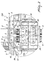
Figure 1 shows a side elevation view of a labelling line with the sleeve-like labels wrapped on the central body; -
Figure 2 shows, in an enlarged view, the station for applying the sleeve-like labels of the labelling line shown inFigure 1 ; -
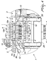
Figure 3 is a side elevation view of the labelling line with the sleeve-like labels fitted over the containers to be labelled; -
Figure 4 shows, in an enlarged view, the station for applying the sleeve-like labels of the labelling line shown inFigure 3 ; -
Figure 5 is a perspective view of a pair of applicators with the associated annular body in the lowered condition; -
Figure 6 shows an end elevation view of the applicators shown infigure 5 ; -
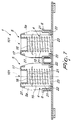
Figure 7 is a sectional view of the applicators with the annular body in the lowered condition, taken along the line marked VII-VII inFigure 6 ; -
Figure 8 is a perspective view of a pair of applicators with the associated annular body in the raised condition; -
Figure 9 shows an end elevation view of the applicators shown infigure 8 ; -
Figure 10 is a sectional view of the applicators with the annular body in the raised condition, taken along the line marked X-X inFigure 9 . - In the embodiments that follow, individual characteristics shown in relation to specific examples may in reality be interchanged with other, different characteristics, existing in other embodiments.
- With reference to the figures, the present invention refers to a device, generally designated by the
reference numeral 1, for applying heat-shrink labels 10 ontocontainers 3 to be labelled such as, for example, jars for yogurts, puddings or desserts. - The
device 1 is, specifically, located at astation 2 for applying a sleeve-like label 10,such station 2 being arranged along alabelling line 100. - The
labelling device 1 has at least oneapplicator 4 which is adapted to feed from below at least one sleeve-like heat-shrink label 10 around arespective container 3 to be labelled. - The
applicator 4 comprises acentral body 5, which is substantially cylindrical or, in general, shaped so as to conform to the shape of the lateral surface of thecontainer 3 to be labelled and is designed to accommodate, around its ownlateral surface 5a, a respective sleeve-like label 10 to be fed to the container to be labelled 3. - Conveniently, the sleeve-
like label 10 is transferred, already formed, by virtue of known means of transfer, to theapplicator 4. - For the purposes of example, the
central body 5 can thus have a cylindricallateral surface 5a with a circular bottom as shown in the figures, but it can also have a bottom that is rectangular or triangular or according to the shape of the lateral surface upon which to apply the label of the body to be labelled 3. - The
applicator 4 has, furthermore, anannular pusher body 6 that is arranged coaxially to, and outside, thecentral body 5 and which can perform a translational motion, on command, with respect to thecentral body 5 along theaxis 101 of thecentral body 5 in order to place the sleeve-like label 10 around arespective container 3 to be labelled. - The average transversal dimensions of the
label 10 are larger (typically by 1-5 mm) than the transversal dimensions of thelateral surface 5a of thecentral body 5 in such a way as to form a meatus, or gap, between the internal surface of thelabel 10 and thelateral surface 5a of thecentral body 5. - The
device 1 is provided with heating means 7 that act in the region of action of the applicator 4 (and therefore at the application station 2), and which are adapted to activate the partial heat-shrinking of the sleeve-like label 10 fitted around the respective container to be labelled 3. - Practically speaking, the heating means 7 that act at the
application station 2 act, for an extremely short time and/or in localised areas of the sleeve-like label 10, in such a way as to permit a partial heat-shrinking that is at least capable of ensuring that the sleeve-like label 10 does not slide downwards during its subsequent movement along thelabelling line 100. - In this regard, it is possible for the
labelling line 100 to be provided with aguide 8 for moving thecontainers 3 to be labelled in the upright condition. - The
guide 8 can be for example constituted by a pair of movement rails, upon which rests the lower surface of the top edge of thecontainers 3. - Conveniently, the heating means 7 can be constituted by first heating means 7a located proximate to the portion of the
movement guide 8 that is arranged at the region of action of theapplicator 4. - With reference to the embodiment shown in the figures from 1 to 4, the first heating means 7a can be constituted by a
perforated duct 9 that can be connected, at afirst end 9a, to asteam supply duct 11, and at the other end, with anend nozzle 12 for discharging the condensate. - The heating means 7 can comprise, furthermore, second heating means 13 which comprise at least one
spray nozzle 13a that is supported by theapplicator 4 and which can be moved simultaneously with theannular body 6 in order to be located beside the sleeve-like label 10 once this has been positioned by the applicator around the container to be labelled 3. Thedevice 1 is conveniently provided with a station for completing the heat-shrinking 14 which is arranged downstream of the region of action of the applicator 4 (and therefore downstream of the application station 2) along themovement guide 8. - The station for completing the heat-shrinking 14 can be implemented, for example, by using
heating ovens 14a which are located below the area through which thecontainers 3 transit. - According to a preferred embodiment, the
central body 5 has, internally, anaxial cavity 15 that accommodates elastic return means, typically aspring 16, that act between the central body 5 (and typically between an upper abutment edge 17) and theannular body 6 and which are adapted to return theannular body 6 to the lowered position (as shown in figures from 5 to 7). - The
device 1 is also provided with movement means 18 for moving theannular body 6 which act in contrast with the elastic return means in order to push theannular body 6 upwards so as to bring, on command, the respective sleeve-like label 10 from thelateral surface 5a of thecylindrical body 5 into engagement with the respective container to be labelled 3. - Advantageously, the movement means
comprise pusher elements 19 which act, on the impulse of drive means and owing to the interposition of means ofkinematic connection 20, at least partially along theaxial cavity 15 of thecentral body 5. - The
central body 5 is provided, conveniently, with firstlongitudinal slots 21 which pass through thelateral surface 5a of thecentral body 5. - The
longitudinal slots 21 can be engaged slidingly byrespective portions 22 for connection between theannular body 6 and acentral element 23 which can move along theaxial cavity 15 under the alternated action of the movement means 18 and the elastic return means. - The
central body 5 also has secondlongitudinal slots 26 which are adapted to reduce the sliding friction between theexternal surface 5a of thecentral body 5 and the internal surface of the sleeve-like labels 10 associated with it. - Conveniently, the
central body 5 has a taperingportion 27 that is directed upwards and which is adapted to facilitate the feeding of the sleeve-like labels 10 to thecentral body 5. - To increase the productivity of the line, the
applicators 4 can be mounted on the external surface of adrum 28 which rotates about an axis that is substantially horizontal and inside which the movement means 18 act. - With this embodiment, a region can be set aside for feeding the sleeve-
like labels 10 to thecentral bodies 5 before they are brought to theapplication station 2. - The present invention further refers to a method for applying heat-shrink
labels 10 to containers to be labelled 3, which comprises the phases of: - feeding a container to be labelled 3 to a
station 2 for applying a sleeve-like heat-shrink label 10; - feeding from below, by means of an
applicator 4, a sleeve-like label 10 to the container to be labelled 3; - heating, by virtue of heating means 7 arranged at the
application station 2, at least one portion of the sleeve-like label 10 fitted around thecontainer 3 to be labelled in order to activate the partial heat-shrinking of the sleeve-like label 10; - sending the
container 3 from theapplication station 2 toward aheating station 14, which is adapted to complete the heat-shrinking of the sleeve-like label 10 onto the container to be labelled 3. - The invention, thus conceived, is susceptible of numerous modifications and variations, all of which are within the scope of the appended claims.
- In practice it has been found that in all the embodiments the invention has fully achieved the aim and objects.
- In particular, the use of the central
cylindrical body 5 facilitates the feeding of the sleeve-like labels 10 to theapplicator 4 and theannular body 6, upon which rests all of the lower edge of the sleeve-like label 10, makes it possible to push the label upwards uniformly without the possibility of localised tensions being created. - In addition, the possibility of carrying out the heat-shrinking process at two different times (and, in particular, in two distinct regions) makes it possible to perceptibly increase the time spent on positioning the label, so drastically reducing the possibility of errors during this critical phase.
- In practice the dimensions may be any, according to the requirements.
- Moreover, all the details may be substituted by other, technically equivalent elements.
- In this regard, there is no specific reason to prevent the
annular body 6 from being divided into one or more sections. - Where the technical features mentioned in any claim are followed by reference signs, those reference signs have been included for the sole purpose of increasing the intelligibility of the claims and accordingly, such reference signs do not have any limiting effect on the interpretation of each element identified by way of example by such reference signs.
Claims (12)
- A device (1) for applying heat-shrink labels (10), comprising at least one applicator (4), which is adapted to feed from below, and located at an application station (2) for applying a sleeve-like label, at least one sleeve-like heat-shrink label (10) around a respective container (3) to be labelled, said applicator (4) comprising a central body (5), which is substantially cylindrical or shaped so as to conform to the shape of said container to be labelled (3), said device (1) comprising means of transfer for transferring said sleeve-like label (10) to the applicator (4), where said sleeve-like label (10) is fed around the lateral surface (5a) of a respective central body (5), characterized in that a gap is provided between the lateral surface (5a) of said central body (5) and the internal surface of the sleeve-like label (10) fitted onto said central body (5), the average transversal dimensions of said sleeve-like label (10) being 1-5 mm larger than the transversal dimensions of said lateral surface (5a) of said central body (5), said device(1) being provided with an annular pusher body (6) which is arranged coaxially and externally to said central body (5) and can perform a translational motion on command with respect to said central body (5) along the axis of said central body (5) in order to place said sleeve-like label (10) around said container to be labelled (3), all of the lower edge of said sleeve-like label (10) resting upon said annular pusher body (6).
- The device (1) for applying heat-shrink labels according to claim 1, characterized in that it comprises heating means (7), which act at a region of action of said at least one applicator (4) and are adapted to activate a partial heat-shrinking of the sleeve-like label (10) fitted around the respective container to be labelled (3).
- The device (1) for applying heat-shrink labels according to claim 2, characterized in that it comprises a guide (8) for moving said containers to be labelled (3) in the upright condition, said heating means (7) comprising first heating means (7a) located proximate to the portion of said movement guide (8) that is arranged at the region of action of said at least one applicator (4).
- The device (1) for applying heat-shrink labels according to claim 3 characterized in that said heating means (7) comprises second heating means (13), which comprise at least one spray nozzle (13a) that is supported by said applicator (4) and can move simultaneously with said annular body (6).
- The device (1) for applying heat-shrink labels according to one or more of the preceding claims 2-4, characterized in that it comprises a station (14) completing the heat-shrinking process which is arranged downstream of said region of action of said at least one applicator (4) along said movement guide (8).
- The device (1) for applying heat-shrink labels according to one or more of the preceding claims, characterized in that said central body (5) is provided internally with an axial cavity (15), which accommodates elastic return means (16) that act between said central body (5) and said annular body (6) and are adapted to return said annular body (6) to the lowered position.
- The device (1) for applying heat-shrink labels according to claim 6, characterized in that it comprises movement means (18) for moving said annular body (6), which act in contrast with said elastic return means in order to push upward said annular body (6) so as to move the respective sleeve-like label (10) into engagement with the respective container to be labelled (3).
- The device (1) for applying heat-shrink labels according to claim 7, characterized in that said movement means (18) act at least partially along said axial cavity (15) of said central body (5).
- The device (1) for applying heat-shrink labels according to claim 8, characterized in that said central body (5) comprises first longitudinal slots (21), which pass through the lateral surface (5a) of said central body (5) and can be engaged slidingly by respective portions (22) for connection between said annular body (6) and a central element (23), which can move along said axial cavity (15), said central element (23) being connected kinematically to said movement means (16) and to said elastic return means.
- The device (1) for applying heat-shrink labels according to one or more of the preceding claims, characterized in that said central body (5) comprises second longitudinal slots (26), which are adapted to reduce the sliding friction between the lateral surface (5a) of said central body (5) and the internal surface of said sleeve-like label (10).
- The device (1) for applying heat-shrink labels according to one or more of the preceding claims, characterized in that said central body (5) has a tapering portion (27) that is directed upward and is adapted to facilitate the feeding of said sleeve-like labels (10) to said central body (5).
- A method for applying heat-shrink labels, comprising the steps of:- feeding a container to be labelled (3) to a station (2) for applying at least one sleeve-like heat-shrink label (10);- transferring a sleeve-like heat-shrink label (10) to an applicator (4), said applicator (4) comprising a central body (5), which is substantially cylindrical or shaped so as to conform to the shape of said container to be labelled (3), said sleeve-like label (10) being fed around the lateral surface (5a) of a respective central body (5), a gap being provided between the lateral surface (5a) of said central body (5) and the internal surface of the sleeve-like label (10) fitted onto said central body (5), the average transversal dimensions of said sleeve-like label (10) being 1-5 mm larger than the transversal dimensions of said lateral surface (5a) of said central body (5);- feeding from below, by means of said applicator (4), said sleeve-like label (10) to said container to be labelled (3), an annular pusher body (6) being arranged coaxially and externally to said central body (5) and being able to perform a translational motion on command with respect to said central body (5) along the axis of said central body (5) in order to place said sleeve-like label (10) around said container to be labelled (3), all of the lower edge of said sleeve-like label (10) resting upon said annular pusher body (6);- heating, by virtue of heating means (7) arranged at said application station (2), at least one portion of said sleeve-like label (10) fitted around said container to be labelled (3) in order to activate the partial heat-shrinking of said sleeve-like label (10);- sending said container (3) from said application station (2) toward a heating station (14), which is adapted to complete the heat-shrinking of said sleeve-like label (10) onto said container to be labelled (3).
Applications Claiming Priority (2)
| Application Number | Priority Date | Filing Date | Title |
|---|---|---|---|
| ITVR2009A000118A IT1395687B1 (en) | 2009-08-03 | 2009-08-03 | DEVICE FOR THE APPLICATION OF THERMORETRIBLE LABELS |
| PCT/IB2010/053483 WO2011015981A1 (en) | 2009-08-03 | 2010-07-30 | Device for applying heat-shrink labels |
Publications (2)
| Publication Number | Publication Date |
|---|---|
| EP2462030A1 EP2462030A1 (en) | 2012-06-13 |
| EP2462030B1 true EP2462030B1 (en) | 2016-08-31 |
Family
ID=42126499
Family Applications (1)
| Application Number | Title | Priority Date | Filing Date |
|---|---|---|---|
| EP10752194.0A Active EP2462030B1 (en) | 2009-08-03 | 2010-07-30 | Device for applying heat-shrink labels |
Country Status (4)
| Country | Link |
|---|---|
| EP (1) | EP2462030B1 (en) |
| ES (1) | ES2612548T3 (en) |
| IT (1) | IT1395687B1 (en) |
| WO (1) | WO2011015981A1 (en) |
Families Citing this family (6)
| Publication number | Priority date | Publication date | Assignee | Title |
|---|---|---|---|---|
| DE102011090102A1 (en) * | 2011-12-29 | 2013-07-04 | Krones Aktiengesellschaft | Apparatus and method for attaching shrink sleeves to containers |
| WO2016027286A1 (en) * | 2014-08-18 | 2016-02-25 | New Tech S.R.L. | Machine for applying shrink sleeve labels and process for applying said labels |
| EP3315425A4 (en) * | 2015-06-23 | 2019-03-06 | Fuji Seal International, Inc. | Film fitting head |
| IT201900003003A1 (en) * | 2019-03-01 | 2020-09-01 | Finpac Italia S R L | MACHINE AND METHOD FOR THE APPLICATION OF TUBULAR LABELS ON CONTAINERS |
| CN110667966B (en) * | 2019-10-24 | 2024-12-06 | 杭州中亚机械股份有限公司 | Label paper carrier |
| CN110697190B (en) * | 2019-10-24 | 2025-01-10 | 杭州中亚机械股份有限公司 | Label paper supply device |
Family Cites Families (5)
| Publication number | Priority date | Publication date | Assignee | Title |
|---|---|---|---|---|
| US3959065A (en) * | 1974-04-25 | 1976-05-25 | Owens-Illinois, Inc. | Method and apparatus for producing plastic-covered containers |
| US4302275A (en) * | 1979-11-27 | 1981-11-24 | Owens-Illinois, Inc. | Apparatus for forming tubular plastic sleeves for application to bottles |
| CN100447054C (en) | 2003-01-29 | 2008-12-31 | 本克包装设备有限公司 | Labeling equipment for containers |
| ITRM20030128A1 (en) * | 2003-03-24 | 2004-09-25 | Enrico Ghini | DEVICE FOR THE APPLICATION AND THERMORETRATION OF |
| ITRE20070082A1 (en) * | 2007-06-22 | 2008-12-23 | Benco Pack Spa | MACHINE AND METHOD FOR CONTAINER LABELING |
-
2009
- 2009-08-03 IT ITVR2009A000118A patent/IT1395687B1/en active
-
2010
- 2010-07-30 ES ES10752194.0T patent/ES2612548T3/en active Active
- 2010-07-30 WO PCT/IB2010/053483 patent/WO2011015981A1/en not_active Ceased
- 2010-07-30 EP EP10752194.0A patent/EP2462030B1/en active Active
Also Published As
| Publication number | Publication date |
|---|---|
| EP2462030A1 (en) | 2012-06-13 |
| WO2011015981A1 (en) | 2011-02-10 |
| IT1395687B1 (en) | 2012-10-16 |
| ITVR20090118A1 (en) | 2011-02-04 |
| ES2612548T3 (en) | 2017-05-17 |
Similar Documents
| Publication | Publication Date | Title |
|---|---|---|
| EP2462030A1 (en) | Device for applying heat-shrink labels | |
| US9193493B2 (en) | Labelling machine | |
| US8627870B2 (en) | Apparatus and method for labeling containers with different types of labels | |
| CN100447054C (en) | Labeling equipment for containers | |
| NL2008718C2 (en) | Labelling plant and method for fixing sleeves around containers. | |
| JP2010530832A (en) | Apparatus and method for attaching labels to containers | |
| WO2004020291A1 (en) | Process and apparatus for forming tubular labels of heat shrinkable film and inserting containers therein | |
| EP2669203B1 (en) | Labelling machine and method | |
| CN101746534B (en) | Device and method for labeling roller supplied label on container | |
| EP2883804B1 (en) | A labelling unit for applying a label onto an article | |
| WO2011077465A1 (en) | A unit for applying a label on a relative article | |
| US9771175B2 (en) | Labelling unit for applying a label onto an article | |
| EP2851334B1 (en) | Container handling apparatus | |
| WO2011018807A1 (en) | A unit for applying a label on a relative article | |
| EP2754616B1 (en) | Label mounting device | |
| EP4116103B1 (en) | MACHINE FOR PRINTING INFORMATION ONTO A CONTAINER | |
| EP3115308A1 (en) | A label application apparatus and method | |
| EP3816057B1 (en) | Heat-shrinking device and heat-shrinking method for heat shrinkable label | |
| EP2673199B1 (en) | A unit for applying a label on a relative article |
Legal Events
| Date | Code | Title | Description |
|---|---|---|---|
| PUAI | Public reference made under article 153(3) epc to a published international application that has entered the european phase |
Free format text: ORIGINAL CODE: 0009012 |
|
| 17P | Request for examination filed |
Effective date: 20120210 |
|
| AK | Designated contracting states |
Kind code of ref document: A1 Designated state(s): AL AT BE BG CH CY CZ DE DK EE ES FI FR GB GR HR HU IE IS IT LI LT LU LV MC MK MT NL NO PL PT RO SE SI SK SM TR |
|
| DAX | Request for extension of the european patent (deleted) | ||
| GRAP | Despatch of communication of intention to grant a patent |
Free format text: ORIGINAL CODE: EPIDOSNIGR1 |
|
| INTG | Intention to grant announced |
Effective date: 20160307 |
|
| GRAS | Grant fee paid |
Free format text: ORIGINAL CODE: EPIDOSNIGR3 |
|
| GRAA | (expected) grant |
Free format text: ORIGINAL CODE: 0009210 |
|
| AK | Designated contracting states |
Kind code of ref document: B1 Designated state(s): AL AT BE BG CH CY CZ DE DK EE ES FI FR GB GR HR HU IE IS IT LI LT LU LV MC MK MT NL NO PL PT RO SE SI SK SM TR |
|
| REG | Reference to a national code |
Ref country code: CH Ref legal event code: EP Ref country code: GB Ref legal event code: FG4D |
|
| REG | Reference to a national code |
Ref country code: IE Ref legal event code: FG4D |
|
| REG | Reference to a national code |
Ref country code: DE Ref legal event code: R096 Ref document number: 602010036026 Country of ref document: DE |
|
| REG | Reference to a national code |
Ref country code: AT Ref legal event code: REF Ref document number: 824748 Country of ref document: AT Kind code of ref document: T Effective date: 20161015 |
|
| REG | Reference to a national code |
Ref country code: LT Ref legal event code: MG4D |
|
| REG | Reference to a national code |
Ref country code: NL Ref legal event code: MP Effective date: 20160831 |
|
| REG | Reference to a national code |
Ref country code: AT Ref legal event code: MK05 Ref document number: 824748 Country of ref document: AT Kind code of ref document: T Effective date: 20160831 |
|
| PG25 | Lapsed in a contracting state [announced via postgrant information from national office to epo] |
Ref country code: FI Free format text: LAPSE BECAUSE OF FAILURE TO SUBMIT A TRANSLATION OF THE DESCRIPTION OR TO PAY THE FEE WITHIN THE PRESCRIBED TIME-LIMIT Effective date: 20160831 Ref country code: LT Free format text: LAPSE BECAUSE OF FAILURE TO SUBMIT A TRANSLATION OF THE DESCRIPTION OR TO PAY THE FEE WITHIN THE PRESCRIBED TIME-LIMIT Effective date: 20160831 Ref country code: NO Free format text: LAPSE BECAUSE OF FAILURE TO SUBMIT A TRANSLATION OF THE DESCRIPTION OR TO PAY THE FEE WITHIN THE PRESCRIBED TIME-LIMIT Effective date: 20161130 Ref country code: HR Free format text: LAPSE BECAUSE OF FAILURE TO SUBMIT A TRANSLATION OF THE DESCRIPTION OR TO PAY THE FEE WITHIN THE PRESCRIBED TIME-LIMIT Effective date: 20160831 |
|
| PG25 | Lapsed in a contracting state [announced via postgrant information from national office to epo] |
Ref country code: GR Free format text: LAPSE BECAUSE OF FAILURE TO SUBMIT A TRANSLATION OF THE DESCRIPTION OR TO PAY THE FEE WITHIN THE PRESCRIBED TIME-LIMIT Effective date: 20161201 Ref country code: SE Free format text: LAPSE BECAUSE OF FAILURE TO SUBMIT A TRANSLATION OF THE DESCRIPTION OR TO PAY THE FEE WITHIN THE PRESCRIBED TIME-LIMIT Effective date: 20160831 Ref country code: AT Free format text: LAPSE BECAUSE OF FAILURE TO SUBMIT A TRANSLATION OF THE DESCRIPTION OR TO PAY THE FEE WITHIN THE PRESCRIBED TIME-LIMIT Effective date: 20160831 Ref country code: NL Free format text: LAPSE BECAUSE OF FAILURE TO SUBMIT A TRANSLATION OF THE DESCRIPTION OR TO PAY THE FEE WITHIN THE PRESCRIBED TIME-LIMIT Effective date: 20160831 Ref country code: LV Free format text: LAPSE BECAUSE OF FAILURE TO SUBMIT A TRANSLATION OF THE DESCRIPTION OR TO PAY THE FEE WITHIN THE PRESCRIBED TIME-LIMIT Effective date: 20160831 |
|
| PG25 | Lapsed in a contracting state [announced via postgrant information from national office to epo] |
Ref country code: RO Free format text: LAPSE BECAUSE OF FAILURE TO SUBMIT A TRANSLATION OF THE DESCRIPTION OR TO PAY THE FEE WITHIN THE PRESCRIBED TIME-LIMIT Effective date: 20160831 Ref country code: EE Free format text: LAPSE BECAUSE OF FAILURE TO SUBMIT A TRANSLATION OF THE DESCRIPTION OR TO PAY THE FEE WITHIN THE PRESCRIBED TIME-LIMIT Effective date: 20160831 |
|
| REG | Reference to a national code |
Ref country code: ES Ref legal event code: FG2A Ref document number: 2612548 Country of ref document: ES Kind code of ref document: T3 Effective date: 20170517 |
|
| PG25 | Lapsed in a contracting state [announced via postgrant information from national office to epo] |
Ref country code: DK Free format text: LAPSE BECAUSE OF FAILURE TO SUBMIT A TRANSLATION OF THE DESCRIPTION OR TO PAY THE FEE WITHIN THE PRESCRIBED TIME-LIMIT Effective date: 20160831 Ref country code: SK Free format text: LAPSE BECAUSE OF FAILURE TO SUBMIT A TRANSLATION OF THE DESCRIPTION OR TO PAY THE FEE WITHIN THE PRESCRIBED TIME-LIMIT Effective date: 20160831 Ref country code: BG Free format text: LAPSE BECAUSE OF FAILURE TO SUBMIT A TRANSLATION OF THE DESCRIPTION OR TO PAY THE FEE WITHIN THE PRESCRIBED TIME-LIMIT Effective date: 20161130 Ref country code: SM Free format text: LAPSE BECAUSE OF FAILURE TO SUBMIT A TRANSLATION OF THE DESCRIPTION OR TO PAY THE FEE WITHIN THE PRESCRIBED TIME-LIMIT Effective date: 20160831 Ref country code: PT Free format text: LAPSE BECAUSE OF FAILURE TO SUBMIT A TRANSLATION OF THE DESCRIPTION OR TO PAY THE FEE WITHIN THE PRESCRIBED TIME-LIMIT Effective date: 20170102 Ref country code: BE Free format text: LAPSE BECAUSE OF FAILURE TO SUBMIT A TRANSLATION OF THE DESCRIPTION OR TO PAY THE FEE WITHIN THE PRESCRIBED TIME-LIMIT Effective date: 20160831 Ref country code: PL Free format text: LAPSE BECAUSE OF FAILURE TO SUBMIT A TRANSLATION OF THE DESCRIPTION OR TO PAY THE FEE WITHIN THE PRESCRIBED TIME-LIMIT Effective date: 20160831 Ref country code: CZ Free format text: LAPSE BECAUSE OF FAILURE TO SUBMIT A TRANSLATION OF THE DESCRIPTION OR TO PAY THE FEE WITHIN THE PRESCRIBED TIME-LIMIT Effective date: 20160831 |
|
| REG | Reference to a national code |
Ref country code: DE Ref legal event code: R097 Ref document number: 602010036026 Country of ref document: DE |
|
| REG | Reference to a national code |
Ref country code: FR Ref legal event code: PLFP Year of fee payment: 8 |
|
| PLBE | No opposition filed within time limit |
Free format text: ORIGINAL CODE: 0009261 |
|
| STAA | Information on the status of an ep patent application or granted ep patent |
Free format text: STATUS: NO OPPOSITION FILED WITHIN TIME LIMIT |
|
| 26N | No opposition filed |
Effective date: 20170601 |
|
| PG25 | Lapsed in a contracting state [announced via postgrant information from national office to epo] |
Ref country code: SI Free format text: LAPSE BECAUSE OF FAILURE TO SUBMIT A TRANSLATION OF THE DESCRIPTION OR TO PAY THE FEE WITHIN THE PRESCRIBED TIME-LIMIT Effective date: 20160831 |
|
| REG | Reference to a national code |
Ref country code: CH Ref legal event code: PL |
|
| GBPC | Gb: european patent ceased through non-payment of renewal fee |
Effective date: 20170730 |
|
| PG25 | Lapsed in a contracting state [announced via postgrant information from national office to epo] |
Ref country code: GB Free format text: LAPSE BECAUSE OF NON-PAYMENT OF DUE FEES Effective date: 20170730 Ref country code: LI Free format text: LAPSE BECAUSE OF NON-PAYMENT OF DUE FEES Effective date: 20170731 Ref country code: CH Free format text: LAPSE BECAUSE OF NON-PAYMENT OF DUE FEES Effective date: 20170731 |
|
| REG | Reference to a national code |
Ref country code: IE Ref legal event code: MM4A |
|
| REG | Reference to a national code |
Ref country code: FR Ref legal event code: PLFP Year of fee payment: 9 |
|
| PG25 | Lapsed in a contracting state [announced via postgrant information from national office to epo] |
Ref country code: LU Free format text: LAPSE BECAUSE OF NON-PAYMENT OF DUE FEES Effective date: 20170730 |
|
| PG25 | Lapsed in a contracting state [announced via postgrant information from national office to epo] |
Ref country code: IE Free format text: LAPSE BECAUSE OF NON-PAYMENT OF DUE FEES Effective date: 20170730 |
|
| PG25 | Lapsed in a contracting state [announced via postgrant information from national office to epo] |
Ref country code: MT Free format text: LAPSE BECAUSE OF NON-PAYMENT OF DUE FEES Effective date: 20170730 |
|
| PG25 | Lapsed in a contracting state [announced via postgrant information from national office to epo] |
Ref country code: AL Free format text: LAPSE BECAUSE OF FAILURE TO SUBMIT A TRANSLATION OF THE DESCRIPTION OR TO PAY THE FEE WITHIN THE PRESCRIBED TIME-LIMIT Effective date: 20160831 |
|
| PG25 | Lapsed in a contracting state [announced via postgrant information from national office to epo] |
Ref country code: MC Free format text: LAPSE BECAUSE OF FAILURE TO SUBMIT A TRANSLATION OF THE DESCRIPTION OR TO PAY THE FEE WITHIN THE PRESCRIBED TIME-LIMIT Effective date: 20160831 Ref country code: HU Free format text: LAPSE BECAUSE OF FAILURE TO SUBMIT A TRANSLATION OF THE DESCRIPTION OR TO PAY THE FEE WITHIN THE PRESCRIBED TIME-LIMIT; INVALID AB INITIO Effective date: 20100730 |
|
| PG25 | Lapsed in a contracting state [announced via postgrant information from national office to epo] |
Ref country code: CY Free format text: LAPSE BECAUSE OF NON-PAYMENT OF DUE FEES Effective date: 20160831 |
|
| PG25 | Lapsed in a contracting state [announced via postgrant information from national office to epo] |
Ref country code: MK Free format text: LAPSE BECAUSE OF FAILURE TO SUBMIT A TRANSLATION OF THE DESCRIPTION OR TO PAY THE FEE WITHIN THE PRESCRIBED TIME-LIMIT Effective date: 20160831 |
|
| PG25 | Lapsed in a contracting state [announced via postgrant information from national office to epo] |
Ref country code: TR Free format text: LAPSE BECAUSE OF FAILURE TO SUBMIT A TRANSLATION OF THE DESCRIPTION OR TO PAY THE FEE WITHIN THE PRESCRIBED TIME-LIMIT Effective date: 20160831 |
|
| PG25 | Lapsed in a contracting state [announced via postgrant information from national office to epo] |
Ref country code: IS Free format text: LAPSE BECAUSE OF FAILURE TO SUBMIT A TRANSLATION OF THE DESCRIPTION OR TO PAY THE FEE WITHIN THE PRESCRIBED TIME-LIMIT Effective date: 20161231 |
|
| REG | Reference to a national code |
Ref country code: DE Ref legal event code: R082 Ref document number: 602010036026 Country of ref document: DE Representative=s name: SCHIEBER - FARAGO PATENTANWAELTE, DE Ref country code: DE Ref legal event code: R082 Ref document number: 602010036026 Country of ref document: DE Representative=s name: FARAGO PATENTANWALTSGESELLSCHAFT MBH, DE |
|
| REG | Reference to a national code |
Ref country code: DE Ref legal event code: R082 Ref document number: 602010036026 Country of ref document: DE Representative=s name: SCHIEBER - FARAGO PATENTANWAELTE, DE |
|
| P01 | Opt-out of the competence of the unified patent court (upc) registered |
Effective date: 20230529 |
|
| PGFP | Annual fee paid to national office [announced via postgrant information from national office to epo] |
Ref country code: FR Payment date: 20250620 Year of fee payment: 16 |
|
| PGFP | Annual fee paid to national office [announced via postgrant information from national office to epo] |
Ref country code: ES Payment date: 20250801 Year of fee payment: 16 |
|
| PGFP | Annual fee paid to national office [announced via postgrant information from national office to epo] |
Ref country code: DE Payment date: 20250620 Year of fee payment: 16 |
|
| PGFP | Annual fee paid to national office [announced via postgrant information from national office to epo] |
Ref country code: IT Payment date: 20250619 Year of fee payment: 16 |