EP2461849B1 - Tray for positioning elongated objects, in particular syringe bodies or syringes - Google Patents
Tray for positioning elongated objects, in particular syringe bodies or syringes Download PDFInfo
- Publication number
- EP2461849B1 EP2461849B1 EP09736669A EP09736669A EP2461849B1 EP 2461849 B1 EP2461849 B1 EP 2461849B1 EP 09736669 A EP09736669 A EP 09736669A EP 09736669 A EP09736669 A EP 09736669A EP 2461849 B1 EP2461849 B1 EP 2461849B1
- Authority
- EP
- European Patent Office
- Prior art keywords
- tray
- openings
- flanges
- projections
- row
- Prior art date
- Legal status (The legal status is an assumption and is not a legal conclusion. Google has not performed a legal analysis and makes no representation as to the accuracy of the status listed.)
- Active
Links
Images

Classifications
-
- A—HUMAN NECESSITIES
- A61—MEDICAL OR VETERINARY SCIENCE; HYGIENE
- A61M—DEVICES FOR INTRODUCING MEDIA INTO, OR ONTO, THE BODY; DEVICES FOR TRANSDUCING BODY MEDIA OR FOR TAKING MEDIA FROM THE BODY; DEVICES FOR PRODUCING OR ENDING SLEEP OR STUPOR
- A61M5/00—Devices for bringing media into the body in a subcutaneous, intra-vascular or intramuscular way; Accessories therefor, e.g. filling or cleaning devices, arm rests
- A61M5/008—Racks for supporting syringes or needles
-
- B—PERFORMING OPERATIONS; TRANSPORTING
- B65—CONVEYING; PACKING; STORING; HANDLING THIN OR FILAMENTARY MATERIAL
- B65D—CONTAINERS FOR STORAGE OR TRANSPORT OF ARTICLES OR MATERIALS, e.g. BAGS, BARRELS, BOTTLES, BOXES, CANS, CARTONS, CRATES, DRUMS, JARS, TANKS, HOPPERS, FORWARDING CONTAINERS; ACCESSORIES, CLOSURES, OR FITTINGS THEREFOR; PACKAGING ELEMENTS; PACKAGES
- B65D25/00—Details of other kinds or types of rigid or semi-rigid containers
- B65D25/02—Internal fittings
- B65D25/10—Devices to locate articles in containers
- B65D25/108—Devices, e.g. plates, presenting apertures through which the articles project
-
- B—PERFORMING OPERATIONS; TRANSPORTING
- B01—PHYSICAL OR CHEMICAL PROCESSES OR APPARATUS IN GENERAL
- B01L—CHEMICAL OR PHYSICAL LABORATORY APPARATUS FOR GENERAL USE
- B01L2200/00—Solutions for specific problems relating to chemical or physical laboratory apparatus
- B01L2200/02—Adapting objects or devices to another
- B01L2200/025—Align devices or objects to ensure defined positions relative to each other
-
- B—PERFORMING OPERATIONS; TRANSPORTING
- B01—PHYSICAL OR CHEMICAL PROCESSES OR APPARATUS IN GENERAL
- B01L—CHEMICAL OR PHYSICAL LABORATORY APPARATUS FOR GENERAL USE
- B01L9/00—Supporting devices; Holding devices
- B01L9/54—Supports specially adapted for pipettes and burettes
Definitions
- the present invention relates to a tray for positioning elongated objects, in particular syringe bodies or syringes.
- elongated objects in particular syringe bodies or syringes.
- Each one of these elongated objects comprises a body, notably cylindrical, and a noncircular flange, having a length greater than its width.
- the flange is located at one end of the cylindrical body, or near this end.
- the flange can be integral with the syringe body or can be formed by a separate part mounted on the proximal end of this body.
- syringe bodies or syringes are to be transported from one site to another site, either when they are manufactured on a site and are filled on another site, or, less frequently, when they are manufactured and filled on the same site and are to be used on another site.
- the tray with the syringe bodies or syringes thereon is placed in a packaging box, which is sealed and sterilized. At destination, the box is opened and the tray is extracted therefrom, the tray being subsequently used for handling and/or filling of the syringe bodies or syringes by automated means.
- a known tray for grouping syringe bodies or syringes includes a plate and a plurality of chimneys projecting from at least a face of this plate, these chimneys being dimensioned to receive the syringe bodies or syringes through them until the flanges of the syringe bodies or syringes bear against the upper free edges of these chimneys.
- the tray according to this patent application does not overcome the above-mentioned drawback, notably because the geometry of the rectangular housings leads to additional handling operations for clipping and unclipping the syringe flanges.
- the object of the present invention is to overcome this drawback.
- the tray concerned includes, in a known way, a plate with spaced apart openings arranged in parallel rows, intended to receive the bodies of the elongated objects, and projections that place the flanges of the elongated objects inserted in these openings in a determined position on the tray when said bodies of these elongated objects are engaged in these openings.
- each flange of an object of said first row is positioned in a space existing between the two adjacent flanges of the objects of said second row, in the immediate vicinity of these two flanges.
- the tray according to the invention thus makes it possible to position the flanges of the elongated objects according to given angular orientations, identical from one row to an adjacent row, and thus to put these flanges in the immediate vicinity one with each other, with imbrications.
- the openings can thus be arranged in positions notably closer than the openings of a tray according to the prior art, and the density of these objects on this tray can be significantly increased, while allowing the external dimensions of the tray to remain identical to those of the existing trays. This conservation of these external dimensions is indeed necessary not to induce too important modifications of the automated treatment units of the elongated objects, in particular of the units for handling and/or filling syringe bodies.
- each projection includes a cylindrical stem and a radial wall, extending radially from this cylindrical stem, said cylindrical stem being arranged substantially between two openings of the same row of openings so that the flanges of the elongated objects engaged in these openings come in its immediate vicinity, as well as the flange of an elongated object engaged in the contiguous opening of the adjacent row, and said radial wall being arranged according to the desired determined angular position of the flanges of the elongated objects and being intended to be inserted between the flanges of the elongated objects inserted in two contiguous openings of two rows of adjacent openings.
- Said projections can also be in the form of rectilinear walls, or of studs having a form corresponding to that of spaces existing between the flanges of two adjacent rows of objects.
- Said projections can be arranged so that the flanges come in contact therewith or come in the immediate vicinity therewith when the objects are in a complete engagement in the openings of the tray, these projections thus allowing maintaining the flanges in said determined angular position.
- said projections include sloped edges forming ramps which the flanges are intended to meet during the engagement of the objects in the openings of the tray and against which these flanges slip further to this meeting, this slip allowing bringing the flanges in said determined angular position.
- the elongated objects can thus be inserted in the openings of the tray according to an unspecified angular position of their flanges, these objects being brought in said determined angular position by the slip of the flanges against said projections.
- This slip can be carried out by itself or be caused for example by a vibration transmitted to the tray.
- the tray includes projections arranged on two diametrically opposed sides of the openings, and the two projections of a same opening include edges of reversed slopes from one projection to the other of this same opening.
- Said sloped edges of the projections can be rectilinear or exhibit a curved form.
- the projections can also exhibit bevelled free edges, i.e. sloped in the direction of the thickness of these projections, which the flanges are intended to meet during the engagement of the objects in the openings of the tray and against which these flanges slip further to this meeting.
- This slip makes it possible to bring the flanges in said determined angular position or contributes to bring these flanges in this position.
- the projections can be interrupted from a row of openings to an adjacent row of openings, or can be continuous from a row of openings to an adjacent row of openings.
- the tray can include no chimneys, in which case said projections are fixed to the plate of this tray; when the tray includes chimneys delimiting said openings for receiving the elongated objects, said projections can be arranged on the level of the free edges of these chimneys.
- Said projections can include retention means making it possible to carry out retention of the flanges, in particular by clamping or snapping.
- the packaging box containing the tray can thus be turned upside down without risk of the flanges coming out of said projections, and thus without loss of said predetermined angular position.
- the tray can also include, with a same aim, chimneys delimiting said openings for receiving said elongated objects, these chimneys having lengths such that the flanges of the elongated objects received therein are, after installation of the tray in a packaging box and installation on the box of a membrane immobilized with respect to the box, located in the immediate vicinity of this membrane.
- the tray can also include, still with a same aim, a heightening base part making it possible to heighten the plate of the tray with respect to a shoulder for supporting this tray arranged in said packaging box, this base part making it possible to raise the tray so that the flanges of the elongated objects placed on the tray are located in the immediate vicinity of a membrane immobilized with respect to the box.
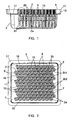
- Figures 1 to 4 show a tray 1 for positioning syringes bodies 2 put in place in a packaging box 3 sealed by a membrane 4 and sterilized.
- This assembly is used to transport the syringe bodies 2 from one site to another, in particular from a site of manufacture of the syringe bodies 2 to a site of filling of these syringe bodies 2 and assembly of the syringes.
- the syringe bodies 2 represented are well-known in themselves. Each one of them is made of glass or plastic or any suitable material, and includes a cylindrical barrel 2a and a proximal flange 2b integral therewith.
- the barrel 2a forms a delivery tip, equipped with a needle, this tip and this needle being covered by a protection cap 2c, yet in place on the syringe body 2 at this stage of manufacture.
- the flange 2b is of noncircular form, having thus a length and a width; it includes two rectilinear longitudinal edges 2b1 and two curved end edges 2b2 centred on the revolution axis of the body 2, like more particularly visible on figure 4 .
- This flange 2b can receive for instance a part such as the one described in the document US 5,667,495 , forming bearing surfaces for a user's fingers at the time of the injection and forming a stop preventing the withdrawal of the piston of the syringe out of the barrel 2a.
- the tray 1 includes, on a face, series of tubular walls 5, or “chimneys", grouped by rows 6, which form upper openings 7 and conduits intended to receive the syringe bodies 2. The latter are engaged in these conduits until their flanges 2b come to rest against the free edge of the chimneys 5 delimiting the openings 7.
- the inner diameters of said conduits are such that these conduits are able to receive the barrels 2a without substantial radial play but with possibility of free pivoting in the conduits.
- chimneys 5 of a row 6 are offset in the longitudinal direction of this row compared to chimneys 5 of the adjacent rows 6 so that chimneys 5 of rows 6 form oblique rows 8 of syringe bodies 2.
- these oblique rows 8 form angles of about 70° with the longitudinal directions of rows 6.
- the chimneys 5 are arranged ones with respect to the others, within the same row 6 or the same row 8, and from a row 6 or row 8 to an adjacent row 6 or row 8, so that the rectilinear edges 2b1 and curved edges 2b2 come in the vicinity to each other when the syringe bodies 2 are inserted in the chimneys 5.
- Figure 3 also shows that the length of the chimneys 5 is such that the proximal surfaces of the flanges 2b, i.e. the surfaces of these flanges opposed to the barrels 2a, come just under the sealing membrane 4 of the box 3 when tray 1 is put in place in this box 3.
- Tray 1 includes moreover, as it is more particularly shown in figures 3 and 4 , positioning projections 10 making it possible to place the flanges 2b in a determined angular position with respect to rows 6.
- Each projection 10 extends perpendicular to the plate 11 of the tray 1, and includes a cylindrical stem 10a and a wall 10b extending radially from this stem 10a, to which it is connected.
- the stem 10a is located substantially halfway of two consecutive chimneys 5 of the same row 6 and has its axis located substantially on a tangent T of the wall of these two chimneys 5 (see figure 4 ).
- Its diameter is such that the curved edges 2b2 of three flanges 2b of three adjacent syringe bodies 2 (two syringe bodies 2 located in the same row 6 and the syringe bodies 2 located in an adjacent row 6) come in the immediate vicinity from it when these syringe bodies 2 are in place in the chimneys 5.
- Its length is such that its free end extends up to the level of the proximal surfaces of the flanges 2b (see figure 3 ).
- the wall 10b extends according to a determined angle with respect to the row 6, according to the desired determined angular position of the flanges 2b on the tray 1, namely according to an angle of about 20° with respect to row 6 in the example shown. As that appears on figures 3 and 4 , the length of this wall 10b is such that it extends up to the membrane 4, being inserted between the rectilinear edges 2b1 of two flanges 2b placed in two adjacent rows 6.
- Each row 6, at one of its ends (that appearing on the left on figure 2 ) includes a projection 10 identical to the other projections 10 of this row 6, placed in alignment with these other projections 10.
- the box 3 forms a peripheral shoulder 15 on which the peripheral zones of the tray 1 come to rest when this tray is inserted in this box.
- the latter can also form snapping ribs 16 retaining these peripheral zones against this shoulder 15 when box 3 is turned upside down.
- the membrane 4 is sealed on an outer edge 17 which the box 3 also includes. Apart from this edge17, this membrane 4 rests on the projections 10.
- the syringe bodies 2 are inserted on the tray 1 with engagement of the flanges 2b between the projections 10 and inducing the determined angular orientation of these flanges like shown on figure 2 and immobilization of the flanges 2b in this determined angular orientation. It is thus possible to arrange the chimneys 5 in close positions, such that the flanges 2b are arranged in the immediate vicinity one with each other, with imbrications, and thus to significantly increase the density of the syringe bodies 2 on the tray 1. A quite higher number of syringe bodies 2 can be inserted on a tray 1, while allowing the external dimensions of the tray 1 to remain identical to those of the existing trays. This conservation of these external dimensions is indeed necessary not to induce too important modifications of the automated treatment units for handling and/or filling the syringe bodies 2.
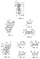
- Figure 5 shows an embodiment in which the chimneys 5 have lengths less than those of the chimneys 5 of the embodiment shown on figure 3 , so that the flanges 2b are remote from the membrane 4.
- the projections 10 include in this case snapping edges 10c, behind which the flanges 2b are retained when they are bearing against the free edges of the chimneys 5, and thus immobilized axially with respect to the tray. The determined angular orientations of the syringe bodies 2 are not thus likely to be lost when box 3 is turned upside down.
- Figure 6 shows an embodiment in which the chimneys 5 also have lengths smaller than those of the chimneys 5 of the embodiment shown on figure 3 but make it possible nevertheless to immediately place the flanges 2b under the membrane 4.
- tray 1 includes a peripheral heightening base part 20 for heightening the plate 11 with respect to shoulder 15.
- Figures 7 and 8 show a tray 1 deprived of the chimneys 5, in which the above mentioned projections are formed by walls 10 arranged on both sides of the openings 7 and oriented according to the desired determined angular position of the flanges 2b.
- Figure 9 shows a tray 1 with chimneys 5. Walls 10 are then arranged on the free ends of the chimneys 5, on two diametrically opposed sides of each one of these chimneys 5.
- Figures 10 to 13 show a tray 1 deprived of the chimneys 5, in which the above mentioned projections are formed by rectilinear walls 10 arranged on both sides of the openings 7. These walls 10 are oriented according to the desired determined angular position of the flanges 2b and extend in a continuous way along rows 8 of openings 7.
- Figures 11 and 12 show that walls 10 including, in front of each opening 7, spaced tips forming rectilinear sloped edges 10d, the sloped edges 10d being located on two opposite sides of the same opening 7 and having reversed slopes. These edges form ramps which the flanges 2b meet during the insertion of the syringe bodies 2 in the openings 7 and against which these flanges slip further to this meeting.
- this slip makes it possible, when the syringe bodies 2 are engaged in the openings 7 with the flanges 2b in an angular position that does not corresponds to the desired determined angular orientation, to make these syringe bodies 2 pivot in these openings 7 until bringing the flanges 2b according to this desired determined angular orientation.
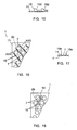
- Figure 15 shows an alternative in which the sloped edges 10d are curved and not rectilinear.
- Figures 16 and 17 show a tray 1 deprived of the chimneys 5, in which the above mentioned projections are also formed by rectilinear walls 10 arranged on both sides of the openings 7, oriented according to the desired determined angular position of the flanges 2b and extending in a continuous way the rows 8 of openings 7.
- walls 10 have bevelled free edges 10e, i.e. sloped according to the thickness of these walls, in the direction of the openings 7.
- the flanges 2b are meet these bevelled free edges 10e when the syringe bodies 2 are engaged in the openings 7 according to an angular position not corresponding to the desired determined angular orientation, the bevelled free edges 10e making it possible to make these syringe bodies 2 pivot in these openings 7 until bringing the flanges 2b according to said desired determined angular orientation.
- Figure 18 shows an embodiment in which the above mentioned projections are comprised of studs 10 having a form corresponding to that of the spaces existing between the flanges 2b of two adjacent rows of syringe bodies 2.
- the invention provides a tray for positioning elongated objects, in particular syringe bodies or syringes, having substantial advantages with respect to the trays of the prior art.
Landscapes
- Health & Medical Sciences (AREA)
- Engineering & Computer Science (AREA)
- Heart & Thoracic Surgery (AREA)
- Vascular Medicine (AREA)
- Anesthesiology (AREA)
- Biomedical Technology (AREA)
- Hematology (AREA)
- Life Sciences & Earth Sciences (AREA)
- Animal Behavior & Ethology (AREA)
- General Health & Medical Sciences (AREA)
- Public Health (AREA)
- Veterinary Medicine (AREA)
- Mechanical Engineering (AREA)
- Infusion, Injection, And Reservoir Apparatuses (AREA)
- Details Of Rigid Or Semi-Rigid Containers (AREA)
Description
- The present invention relates to a tray for positioning elongated objects, in particular syringe bodies or syringes. Each one of these elongated objects comprises a body, notably cylindrical, and a noncircular flange, having a length greater than its width. In the case of a syringe body, the flange is located at one end of the cylindrical body, or near this end. The flange can be integral with the syringe body or can be formed by a separate part mounted on the proximal end of this body.
- It is frequent that syringe bodies or syringes are to be transported from one site to another site, either when they are manufactured on a site and are filled on another site, or, less frequently, when they are manufactured and filled on the same site and are to be used on another site.
- For this transport, it is current to group the syringe bodies or syringes on a tray having openings and tubular walls or chimneys coaxially surrounding these openings, the openings receiving the syringe bodies and the flanges bearing against said tubular walls or chimneys. The tray with the syringe bodies or syringes thereon is placed in a packaging box, which is sealed and sterilized. At destination, the box is opened and the tray is extracted therefrom, the tray being subsequently used for handling and/or filling of the syringe bodies or syringes by automated means.
- A known tray for grouping syringe bodies or syringes includes a plate and a plurality of chimneys projecting from at least a face of this plate, these chimneys being dimensioned to receive the syringe bodies or syringes through them until the flanges of the syringe bodies or syringes bear against the upper free edges of these chimneys.
- With this tray, however, the number of syringe bodies or syringes that can be installed on a same tray is limited. This limitation has a direct consequence on the number of packaging boxes having to be used to transport a given number of syringe bodies or syringes and thus on the cost of the packaging and of the transport of these syringe bodies or syringes. For the user, it is necessary to open and handle a significant number of packaging boxes to process a given number of syringe bodies or syringes.
- In order to increase the density of syringes in a tray, and thus minimizing the handling operations, it would be useful for instance to have the rows of syringes closer one to another; however, due to the particular shape of the syringe flanges, it is not possible, with conventional trays, to have syringe rows closer because flanges might then contact and there is a high risk of breakage during handling operations.
- It is besides known by the
document EP 1 449 551 A1 to provide the plate of the tray with projecting walls forming rectangular housings for receiving the flanges of the syringe bodies. These housings orient these flanges in a determined position on the tray, in which the length and the width of the flanges are perpendicular to the rows and the rows of syringe bodies on the tray. - The tray according to this patent application does not overcome the above-mentioned drawback, notably because the geometry of the rectangular housings leads to additional handling operations for clipping and unclipping the syringe flanges.
- The object of the present invention is to overcome this drawback.
- The tray concerned includes, in a known way, a plate with spaced apart openings arranged in parallel rows, intended to receive the bodies of the elongated objects, and projections that place the flanges of the elongated objects inserted in these openings in a determined position on the tray when said bodies of these elongated objects are engaged in these openings.
- According to the invention,
- said projections are arranged so as to place the length of said flanges in a determined angular position with respect to the rows of openings, and
- the openings of a first row of openings are arranged with respect to a second row of openings adjacent to said first row, such that after installation of the elongated objects on the tray, the flanges of the objects inserted in the openings of said the first row imbricates with the flanges of the objects inserted in the openings of said second row.
- By "determined angular position", it must be understood that the lengths of the flanges are neither parallel nor perpendicular to the longitudinal directions of the rows of openings.
- By "imbricates", it must be understood that each flange of an object of said first row is positioned in a space existing between the two adjacent flanges of the objects of said second row, in the immediate vicinity of these two flanges.
- The tray according to the invention thus makes it possible to position the flanges of the elongated objects according to given angular orientations, identical from one row to an adjacent row, and thus to put these flanges in the immediate vicinity one with each other, with imbrications. The openings can thus be arranged in positions notably closer than the openings of a tray according to the prior art, and the density of these objects on this tray can be significantly increased, while allowing the external dimensions of the tray to remain identical to those of the existing trays. This conservation of these external dimensions is indeed necessary not to induce too important modifications of the automated treatment units of the elongated objects, in particular of the units for handling and/or filling syringe bodies.
- This increase in the density of the number of elongated objects makes it possible to reduce the number of packagings that are necessary for the conditioning and the transport of a given number of these objects, and thus to reduce the costs of conditioning and transporting these objects. The subsequent operations of opening and handling the boxes containing these objects are also reduced accordingly.
- Said projections of the tray can have any appropriate shape making it possible to maintain the flanges in said angular position when the elongated objects are in place in the openings of the tray. According to a preferred embodiment of the invention, each projection includes a cylindrical stem and a radial wall, extending radially from this cylindrical stem, said cylindrical stem being arranged substantially between two openings of the same row of openings so that the flanges of the elongated objects engaged in these openings come in its immediate vicinity, as well as the flange of an elongated object engaged in the contiguous opening of the adjacent row, and said radial wall being arranged according to the desired determined angular position of the flanges of the elongated objects and being intended to be inserted between the flanges of the elongated objects inserted in two contiguous openings of two rows of adjacent openings.
- Said projections can also be in the form of rectilinear walls, or of studs having a form corresponding to that of spaces existing between the flanges of two adjacent rows of objects.
- Said projections can be arranged so that the flanges come in contact therewith or come in the immediate vicinity therewith when the objects are in a complete engagement in the openings of the tray, these projections thus allowing maintaining the flanges in said determined angular position.
- These projections thus only make it possible to maintain the flanges in said determined angular position. The orientation of these flanges necessary for their engagement near the projections or in the immediate vicinity of these projections is then carried out by adequate angular positioning of the objects at the moment of their installation on the tray, this positioning being operated manually or mechanically.
- According to another possibility, said projections include sloped edges forming ramps which the flanges are intended to meet during the engagement of the objects in the openings of the tray and against which these flanges slip further to this meeting, this slip allowing bringing the flanges in said determined angular position.
- The elongated objects can thus be inserted in the openings of the tray according to an unspecified angular position of their flanges, these objects being brought in said determined angular position by the slip of the flanges against said projections. This slip can be carried out by itself or be caused for example by a vibration transmitted to the tray.
- Preferably, in this case, the tray includes projections arranged on two diametrically opposed sides of the openings, and the two projections of a same opening include edges of reversed slopes from one projection to the other of this same opening.
- Said sloped edges of the projections can be rectilinear or exhibit a curved form.
- The projections can also exhibit bevelled free edges, i.e. sloped in the direction of the thickness of these projections, which the flanges are intended to meet during the engagement of the objects in the openings of the tray and against which these flanges slip further to this meeting.
- This slip makes it possible to bring the flanges in said determined angular position or contributes to bring these flanges in this position.
- The projections can be interrupted from a row of openings to an adjacent row of openings, or can be continuous from a row of openings to an adjacent row of openings.
- The tray can include no chimneys, in which case said projections are fixed to the plate of this tray; when the tray includes chimneys delimiting said openings for receiving the elongated objects, said projections can be arranged on the level of the free edges of these chimneys.
- Said projections can include retention means making it possible to carry out retention of the flanges, in particular by clamping or snapping.
- The packaging box containing the tray can thus be turned upside down without risk of the flanges coming out of said projections, and thus without loss of said predetermined angular position.
- The tray can also include, with a same aim, chimneys delimiting said openings for receiving said elongated objects, these chimneys having lengths such that the flanges of the elongated objects received therein are, after installation of the tray in a packaging box and installation on the box of a membrane immobilized with respect to the box, located in the immediate vicinity of this membrane.
- The tray can also include, still with a same aim, a heightening base part making it possible to heighten the plate of the tray with respect to a shoulder for supporting this tray arranged in said packaging box, this base part making it possible to raise the tray so that the flanges of the elongated objects placed on the tray are located in the immediate vicinity of a membrane immobilized with respect to the box.
- The invention will be readily understood, and other features and advantages thereof will appear, in reference to the appended diagrammatic drawing, representative, as non-restrictive examples, several possible embodiments of the tray which it relates to.
-
Figure 1 is a side view, partially cut out, of a tray for positioning syringe bodies according to a first embodiment, this tray being placed in a sealed and sterilized packaging box; -
figure 2 is a top view of this tray; -
figure 3 is an enlarged scale view of the part surrounded by a circle onfigure 1 ; -
figure 4 is an enlarged scale view of the part surrounded by a circle onfigure 2 ; -
figure 5 is a view similar tofigure 3 of the tray according to another embodiment; -
figure 6 is a side cut-out partial view of the tray according to another embodiment; -
figure 7 is a partial top view of the tray according to another embodiment, the syringe bodies being shown in dashed lines; -
figure 8 of it is a cross-section according to the line VIII-VIII offigure 7 ; -
figure 9 is a partial top view of the tray according to another embodiment; -
figure 10 is a partial top view of the tray according to still another embodiment, the syringe bodies being shown in dashed lines; -
figure 11 is a sectional view according to the line XI-XI offigure 10 ; -
figure 12 is a sectional view according to the line XII-XII offigure 10 ; -
figure 13 is a cross-section according to the line XI-XI offigure 10 , showing two syringe bodies in dashed lines, the one on left side on the figure being in the course of installation on the tray and the one on the right side on the figure is installed on the tray; -
figure 14 is a view of the two syringe bodies offigure 13 in the respective positions which they occupy on thisfigure 13 ; -
figure 15 is a view of the tray similar tofigure 11 according to another embodiment; -
figure 16 is a view of the tray similar tofigure 10 according to still another embodiment; -
figure 17 of it is a view in section according to line XVII-XVII offigure 16 ; and -
figure 18 is a view of the tray similar tofigure 10 according to still another embodiment. - By simplification, the parts or elements of an embodiment which are found in an identical or similar way in another embodiment will be identified by the same numerical reference and will not be described again.
-
Figures 1 to 4 show atray 1 for positioningsyringes bodies 2 put in place in apackaging box 3 sealed by amembrane 4 and sterilized. This assembly is used to transport thesyringe bodies 2 from one site to another, in particular from a site of manufacture of thesyringe bodies 2 to a site of filling of thesesyringe bodies 2 and assembly of the syringes. - The
syringe bodies 2 represented are well-known in themselves. Each one of them is made of glass or plastic or any suitable material, and includes acylindrical barrel 2a and aproximal flange 2b integral therewith. Thebarrel 2a forms a delivery tip, equipped with a needle, this tip and this needle being covered by aprotection cap 2c, yet in place on thesyringe body 2 at this stage of manufacture. Theflange 2b is of noncircular form, having thus a length and a width; it includes two rectilinear longitudinal edges 2b1 and two curved end edges 2b2 centred on the revolution axis of thebody 2, like more particularly visible onfigure 4 . Thisflange 2b can receive for instance a part such as the one described in the documentUS 5,667,495 , forming bearing surfaces for a user's fingers at the time of the injection and forming a stop preventing the withdrawal of the piston of the syringe out of thebarrel 2a. - The
tray 1 includes, on a face, series oftubular walls 5, or "chimneys", grouped byrows 6, which formupper openings 7 and conduits intended to receive thesyringe bodies 2. The latter are engaged in these conduits until theirflanges 2b come to rest against the free edge of thechimneys 5 delimiting theopenings 7. The inner diameters of said conduits are such that these conduits are able to receive thebarrels 2a without substantial radial play but with possibility of free pivoting in the conduits. - It appears on
figure 2 thatchimneys 5 of arow 6 are offset in the longitudinal direction of this row compared tochimneys 5 of theadjacent rows 6 so thatchimneys 5 ofrows 6 formoblique rows 8 ofsyringe bodies 2. In the embodiment shown, theseoblique rows 8 form angles of about 70° with the longitudinal directions ofrows 6. It also appears that thechimneys 5 are arranged ones with respect to the others, within thesame row 6 or thesame row 8, and from arow 6 orrow 8 to anadjacent row 6 orrow 8, so that the rectilinear edges 2b1 and curved edges 2b2 come in the vicinity to each other when thesyringe bodies 2 are inserted in thechimneys 5. -
Figure 3 also shows that the length of thechimneys 5 is such that the proximal surfaces of theflanges 2b, i.e. the surfaces of these flanges opposed to thebarrels 2a, come just under the sealingmembrane 4 of thebox 3 whentray 1 is put in place in thisbox 3. -
Tray 1 includes moreover, as it is more particularly shown infigures 3 and 4 ,positioning projections 10 making it possible to place theflanges 2b in a determined angular position with respect torows 6. Eachprojection 10 extends perpendicular to theplate 11 of thetray 1, and includes acylindrical stem 10a and awall 10b extending radially from thisstem 10a, to which it is connected. Thestem 10a is located substantially halfway of twoconsecutive chimneys 5 of thesame row 6 and has its axis located substantially on a tangent T of the wall of these two chimneys 5 (seefigure 4 ). Its diameter is such that the curved edges 2b2 of threeflanges 2b of three adjacent syringe bodies 2 (twosyringe bodies 2 located in thesame row 6 and thesyringe bodies 2 located in an adjacent row 6) come in the immediate vicinity from it when thesesyringe bodies 2 are in place in thechimneys 5. Its length is such that its free end extends up to the level of the proximal surfaces of theflanges 2b (seefigure 3 ). Thewall 10b extends according to a determined angle with respect to therow 6, according to the desired determined angular position of theflanges 2b on thetray 1, namely according to an angle of about 20° with respect torow 6 in the example shown. As that appears onfigures 3 and 4 , the length of thiswall 10b is such that it extends up to themembrane 4, being inserted between the rectilinear edges 2b1 of twoflanges 2b placed in twoadjacent rows 6. - Each
row 6, at one of its ends (that appearing on the left onfigure 2 ) includes aprojection 10 identical to theother projections 10 of thisrow 6, placed in alignment with theseother projections 10. - The
box 3 forms aperipheral shoulder 15 on which the peripheral zones of thetray 1 come to rest when this tray is inserted in this box. The latter can also form snappingribs 16 retaining these peripheral zones against thisshoulder 15 whenbox 3 is turned upside down. - The
membrane 4 is sealed on anouter edge 17 which thebox 3 also includes. Apart from this edge17, thismembrane 4 rests on theprojections 10. - In practice, the
syringe bodies 2 are inserted on thetray 1 with engagement of theflanges 2b between theprojections 10 and inducing the determined angular orientation of these flanges like shown onfigure 2 and immobilization of theflanges 2b in this determined angular orientation. It is thus possible to arrange thechimneys 5 in close positions, such that theflanges 2b are arranged in the immediate vicinity one with each other, with imbrications, and thus to significantly increase the density of thesyringe bodies 2 on thetray 1. A quite higher number ofsyringe bodies 2 can be inserted on atray 1, while allowing the external dimensions of thetray 1 to remain identical to those of the existing trays. This conservation of these external dimensions is indeed necessary not to induce too important modifications of the automated treatment units for handling and/or filling thesyringe bodies 2. - This increase in the density reduces the number of
boxes 3 necessary for the conditioning and the transport of a given number ofsyringe bodies 2, and thus the costs of conditioning and transport of thesesyringe bodies 2. -
Figure 5 shows an embodiment in which thechimneys 5 have lengths less than those of thechimneys 5 of the embodiment shown onfigure 3 , so that theflanges 2b are remote from themembrane 4. Theprojections 10 include in thiscase snapping edges 10c, behind which theflanges 2b are retained when they are bearing against the free edges of thechimneys 5, and thus immobilized axially with respect to the tray. The determined angular orientations of thesyringe bodies 2 are not thus likely to be lost whenbox 3 is turned upside down. -
Figure 6 shows an embodiment in which thechimneys 5 also have lengths smaller than those of thechimneys 5 of the embodiment shown onfigure 3 but make it possible nevertheless to immediately place theflanges 2b under themembrane 4. Indeed, in this case,tray 1 includes a peripheral heighteningbase part 20 for heightening theplate 11 with respect toshoulder 15. -
Figures 7 and 8 show atray 1 deprived of thechimneys 5, in which the above mentioned projections are formed bywalls 10 arranged on both sides of theopenings 7 and oriented according to the desired determined angular position of theflanges 2b. -
Figure 9 shows atray 1 withchimneys 5.Walls 10 are then arranged on the free ends of thechimneys 5, on two diametrically opposed sides of each one of thesechimneys 5. -
Figures 10 to 13 show atray 1 deprived of thechimneys 5, in which the above mentioned projections are formed byrectilinear walls 10 arranged on both sides of theopenings 7. Thesewalls 10 are oriented according to the desired determined angular position of theflanges 2b and extend in a continuous way alongrows 8 ofopenings 7.Figures 11 and 12 show thatwalls 10 including, in front of eachopening 7, spaced tips forming rectilinear slopededges 10d, the slopededges 10d being located on two opposite sides of thesame opening 7 and having reversed slopes. These edges form ramps which theflanges 2b meet during the insertion of thesyringe bodies 2 in theopenings 7 and against which these flanges slip further to this meeting. As shown onfigures 13 and 14 , this slip makes it possible, when thesyringe bodies 2 are engaged in theopenings 7 with theflanges 2b in an angular position that does not corresponds to the desired determined angular orientation, to make thesesyringe bodies 2 pivot in theseopenings 7 until bringing theflanges 2b according to this desired determined angular orientation. -
Figure 15 shows an alternative in which the slopededges 10d are curved and not rectilinear. -
Figures 16 and 17 show atray 1 deprived of thechimneys 5, in which the above mentioned projections are also formed byrectilinear walls 10 arranged on both sides of theopenings 7, oriented according to the desired determined angular position of theflanges 2b and extending in a continuous way therows 8 ofopenings 7. In this case, as it is visible onfigure 17 ,walls 10 have bevelledfree edges 10e, i.e. sloped according to the thickness of these walls, in the direction of theopenings 7. In the same manner that previously described, theflanges 2b are meet these bevelledfree edges 10e when thesyringe bodies 2 are engaged in theopenings 7 according to an angular position not corresponding to the desired determined angular orientation, the bevelledfree edges 10e making it possible to make thesesyringe bodies 2 pivot in theseopenings 7 until bringing theflanges 2b according to said desired determined angular orientation. -
Figure 18 shows an embodiment in which the above mentioned projections are comprised ofstuds 10 having a form corresponding to that of the spaces existing between theflanges 2b of two adjacent rows ofsyringe bodies 2. - As appears from the preceding, the invention provides a tray for positioning elongated objects, in particular syringe bodies or syringes, having substantial advantages with respect to the trays of the prior art.
- The invention was described above in reference to embodiments provided purely as examples. It goes without saying that it is not limited to these embodiments, but that it extends to all embodiments covered by the appended claims.
Claims (15)
- Tray (1) for positioning elongated objects, each having a cylindrical body (2a) and a noncircular flange (2b) having a length greater than its width, the tray (1) including a plate with spaced apart openings (7) arranged in parallel rows (6), intended to receive the bodies (2a) of the elongated objects, and the tray (1) having projections (10) that place the flanges (2b) of the elongated objects inserted in these openings (7) in a determined position on the tray (1) when said bodies (2a) of these elongated objects are engaged in these openings (7);
characterized in that:- said projections (10) are arranged so as to place the length of said flanges (2b) in a determined angular position with respect to at least one of the rows (6) of openings (7), and- the openings (7) of a first row (6) of openings (7) are arranged with respect to a second row (6) of openings (7) adjacent to said first row (6), such that after installation of the elongated objects on the tray (1), the flanges (2b) of the objects inserted in the openings (7) of said the first row (6) imbricates with the flanges (2b) of the objects inserted in the openings (7) of said second row (6). - Tray (1) according to claim 1, characterized in that each projection (10) includes a cylindrical stem (10a) and a radial wall (10b), extending radially from this cylindrical stem (10a), said cylindrical stem (10a) being arranged substantially between two openings (7) of the same row of openings (7) so that the flanges (2b) of the elongated objects engaged in these openings (7) come in its immediate vicinity, as well as the flange (2b) of an elongated object engaged in the contiguous opening (7) of the adjacent row (6), and said radial wall (10b) being arranged according to the desired determined angular position of the flanges (2b) of the elongated objects and being intended to be inserted between the flanges (2b) of the elongated objects inserted in two contiguous openings (7) of two rows (6) of adjacent openings (7).
- Tray (1) according to claim 1, characterized in that said projections (10) are in the form of rectilinear walls or of studs (10e) having a form corresponding to spaces remaining between the flanges (2b) of two adjacent rows (6) of objects.
- Tray (1) according to anyone of claims 1-3, characterized in that said projections (10) are arranged so that the flanges (2b) come in contact therewith or come in the immediate vicinity therewith when the elongated objects are in a complete engagement in the openings (7) of the tray (1), these projections (10) thus allowing to maintain the flanges (2b) in said determined angular position.
- Tray (1) according to anyone of claims 1-3, characterized in that said projections (10) include sloped edges (10d) forming ramps which the flanges (2b) are intended to meet during the engagement of the objects in the openings (7) of the tray (1) and against which these flanges (2b) slip further to this meeting, this slip allowing to bring the flanges (2b) in said determined angular position.
- Tray (1) according to claim 5, characterized in that said projections (10) are arranged on two diametrically opposed sides of the openings (7), and said two projections (10) of a same opening (7) include edges (10d) of reversed slopes from one projection (10) to the other of this same opening (7).
- Tray (1) according to claim 5 or claim 6, characterized in that said sloped edges (10d) of said projections (10) are rectilinear.
- Tray (1) according to claim 5 or claim 6, characterized in that said sloped edges of the projections (10) exhibit a curved form.
- Tray (1) according to one of claims 1 to 7, characterized in that the projections (10) exhibit bevelled free edges (10e), which the flanges (2b) are intended to meet during the engagement of the objects in the openings (7) of the tray (1) and against which these flanges (2b) slip further to this meeting.
- Tray (1) according to one of claims 1 to 9, characterized in that said projections (10) are interrupted from a row of openings (7) to an adjacent row of openings (7).
- Tray (1) according to one of claims 1 to 9, characterized in that said projections (10) are continuous from a row of openings (7) to an adjacent row of openings (7).
- Tray (1) according to one of claims 1 to 11, characterized in that it includes chimneys (5) delimiting said openings (7) for the engagement of the objects, and in that said projections (10) are arranged on the level of the free ends of these chimneys (5).
- Tray (1) according to one of claims 1 to 11, characterized in that said projections (10) include retention means (10c) making it possible to carry out retention of the flanges (2b), in particular by clamping or snapping.
- Tray (1) according to one of claims 1 to 11, characterized in that it includes chimneys (5) delimiting said openings (7) for receiving said elongated objects, these chimneys (5) having lengths such that the flanges (2b) of the elongated objects received therein are, after installation of the tray (1) in a packaging box (3) and installation on the box of a membrane (4) immobilized with respect to the box (3), in the immediate vicinity of this membrane (4).
- Tray (1) according to one of claims 1 to 11, characterized in that it includes a heightening base part (20) making it possible to heighten the plate (11) of the tray (1) with respect to a shoulder (15) for supporting this tray (1) arranged in a packaging box (11), this base part (20) making it possible to raise the tray (1) so that the flanges (2b) of the elongated objects placed on the tray (1) are located in the immediate vicinity of a membrane (4) immobilized with respect to the box (3).
Applications Claiming Priority (1)
| Application Number | Priority Date | Filing Date | Title |
|---|---|---|---|
| PCT/IB2009/006907 WO2011015896A1 (en) | 2009-08-07 | 2009-08-07 | Tray for positioning elongated objects, in particular syringe bodies or syringes |
Publications (2)
| Publication Number | Publication Date |
|---|---|
| EP2461849A1 EP2461849A1 (en) | 2012-06-13 |
| EP2461849B1 true EP2461849B1 (en) | 2013-03-20 |
Family
ID=42110259
Family Applications (1)
| Application Number | Title | Priority Date | Filing Date |
|---|---|---|---|
| EP09736669A Active EP2461849B1 (en) | 2009-08-07 | 2009-08-07 | Tray for positioning elongated objects, in particular syringe bodies or syringes |
Country Status (6)
| Country | Link |
|---|---|
| US (3) | US20120193256A1 (en) |
| EP (1) | EP2461849B1 (en) |
| JP (1) | JP5336658B2 (en) |
| CN (1) | CN102481403B (en) |
| ES (1) | ES2407662T3 (en) |
| WO (1) | WO2011015896A1 (en) |
Families Citing this family (44)
| Publication number | Priority date | Publication date | Assignee | Title |
|---|---|---|---|---|
| CN101868273B (en) | 2007-10-02 | 2014-10-15 | 莱蒙德尔有限公司 | External drug pump |
| GB201004102D0 (en) * | 2010-03-12 | 2010-04-28 | Liversidge Barry P | Syringe barrels and handling systems |
| EP2621552B1 (en) | 2010-09-28 | 2016-06-29 | Becton Dickinson France | Packaging for cylindrical containers |
| JP4685198B1 (en) * | 2010-11-11 | 2011-05-18 | 株式会社アルテ | Manufacturing method of packaging plate, syringe holding container, and container combined syringe |
| DE102011015112A1 (en) * | 2011-03-21 | 2012-09-27 | Vetter Pharma-Fertigung GmbH & Co. KG | Container, holding device, holding system and injection aid |
| DE102012103896A1 (en) | 2012-05-03 | 2013-11-07 | Schott Ag | Supporting structure for simultaneously holding a plurality of medical or pharmaceutical containers and transport or packaging container with self |
| DE102012103898A1 (en) | 2012-05-03 | 2013-11-07 | Schott Ag | Supporting structure for simultaneously holding a plurality of medical or pharmaceutical containers and transport or packaging container with self |
| DE102012103899B4 (en) | 2012-05-03 | 2016-09-22 | Schott Ag | Method and device for treating containers for storing substances for medical or pharmaceutical applications |
| DE102012110339B4 (en) | 2012-05-03 | 2014-04-10 | Schott Ag | Holding structure for simultaneously holding a plurality of medical or pharmaceutical containers as well as transport or packaging containers with self and method for treating such containers |
| EP2659981B1 (en) | 2012-05-03 | 2016-03-23 | Schott AG | Transport or packaging container with a support structure for simultaneously holding a plurality of containers for medical, pharmaceutical or cosmetic applications and method for treating such containers |
| DE102012108215A1 (en) * | 2012-07-13 | 2014-01-16 | Schott Ag | Method for treating or processing containers used for storing e.g. medical substances, involves automatically passing containers opened at one end, through processing stations for treatment or processing, with conveying device |
| KR101655726B1 (en) | 2012-05-03 | 2016-09-07 | 쇼오트 아게 | Method and device for treating containers and substances stored therein for medical, pharmaceutical or cosmetic applications |
| DE102012111624A1 (en) | 2012-05-03 | 2013-11-07 | Schott Ag | Process for treating or processing containers for medical or pharmaceutical applications and carriers and transport or packaging containers therefor |
| EP2844936B1 (en) | 2012-05-03 | 2016-10-12 | Schott AG | Method and device for treating containers and substances stored therein for medical, pharmaceutical or cosmetic applications |
| KR20150009982A (en) | 2012-05-03 | 2015-01-27 | 쇼오트 아게 | Method and device for treating containers and substances stored therein for medical, pharmaceutical or cosmetic applications |
| MX368397B (en) | 2012-10-12 | 2019-10-01 | Int Flavors & Fragrances Inc | Enhanced deposition of ethyl vanillin or vanillin with friable microcapsules. |
| ES2688418T3 (en) | 2012-10-31 | 2018-11-02 | Daikyo Seiko, Ltd. | Receptacle tray |
| US9408965B2 (en) * | 2014-10-31 | 2016-08-09 | Tolmar, Inc. | Method and system for handling and transporting syringes |
| DE102015108066A1 (en) | 2015-05-21 | 2016-11-24 | Gerresheimer Bünde Gmbh | syringe nest |
| US10576207B2 (en) | 2015-10-09 | 2020-03-03 | West Pharma. Services IL, Ltd. | Angled syringe patch injector |
| CN113648488B (en) | 2015-10-09 | 2024-03-29 | 西医药服务以色列分公司 | Curved fluid path attachment to prefilled fluid reservoir |
| US11311674B2 (en) | 2016-01-21 | 2022-04-26 | West Pharma. Services IL, Ltd. | Medicament delivery device comprising a visual indicator |
| CN111544704B (en) | 2016-01-21 | 2022-06-03 | 西医药服务以色列有限公司 | Force containment in autoinjectors |
| WO2017127215A1 (en) | 2016-01-21 | 2017-07-27 | Medimop Medical Projects Ltd. | Needle insertion and retraction mechanism |
| WO2017132554A1 (en) * | 2016-01-27 | 2017-08-03 | West Pharmaceutical Services, Inc. | Syringe nest with hexagonal chimneys and center offset |
| DE102016201268A1 (en) * | 2016-01-28 | 2017-08-03 | Schott Schweiz Ag | Support plate for pharmaceutical containers |
| WO2017161076A1 (en) | 2016-03-16 | 2017-09-21 | Medimop Medical Projects Ltd. | Staged telescopic screw assembly having different visual indicators |
| CN113577438B (en) | 2016-08-01 | 2023-05-23 | 西医药服务以色列有限公司 | Partial door closing prevention spring |
| CN109562229B (en) | 2016-08-01 | 2021-07-13 | 西医药服务以色列有限公司 | Anti-Rotation Cartridge Pin |
| WO2018144733A1 (en) | 2017-02-03 | 2018-08-09 | Biotix, Inc. | Nested pipette tip arrays and related methods |
| USD854185S1 (en) | 2017-02-03 | 2019-07-16 | Biotix, Inc. | Pipette tip receptacle plate |
| WO2018222521A1 (en) | 2017-05-30 | 2018-12-06 | West Pharma. Services IL, Ltd. | Modular drive train for wearable injector |
| IT201800003376A1 (en) * | 2018-03-08 | 2019-09-08 | Nuova Ompi Srl | STRUCTURE FOR THE PACKAGING OF CONTAINERS FOR PHARMACEUTICAL USE |
| US11298455B2 (en) | 2018-05-02 | 2022-04-12 | Becton Dickinson France | Holding device configured to support a plurality of medical containers such as syringes |
| US11161671B2 (en) * | 2019-07-18 | 2021-11-02 | Daikyo Seiko Ltd. | Medical device container |
| WO2021126679A1 (en) * | 2019-12-16 | 2021-06-24 | Merck Sharp & Dohme Corp. | Pre-filled syringe stopper retainer having projections or receivers and methods of using same |
| DE102020203992B4 (en) | 2020-03-27 | 2022-12-15 | Gerresheimer Regensburg Gmbh | System, device and method for forming a holding device or a syringe nest with insertion bevels for transporting and storing medical containers |
| US12138417B2 (en) * | 2020-06-25 | 2024-11-12 | Sanofi | Workpiece carrier for components of drug delivery devices |
| CN116744988B (en) * | 2021-01-26 | 2026-07-10 | 贝克顿迪金森法国公司 | Inlay set |
| EP4233935B1 (en) | 2022-02-23 | 2026-04-29 | Becton Dickinson France | Holding device for medical containers with reinforcing ribs for increasing stiffness and reducing deflection |
| US20250177253A1 (en) | 2022-02-23 | 2025-06-05 | Becton Dickinson France | Holding Device for Medical Containers With Plates of Different Elevations |
| EP4537870A1 (en) | 2023-10-13 | 2025-04-16 | Becton, Dickinson and Company | Medical container holding device with rigidity-enhancing raised plateau |
| EP4635528A1 (en) | 2024-04-15 | 2025-10-22 | SCHOTT Pharma Schweiz AG | Assembly for pharmaceutical containers for reducing contact between containers and sidewalls of assembly |
| CN119329889A (en) * | 2024-10-31 | 2025-01-21 | 江苏乐聚医药科技有限公司 | A nesting board |
Family Cites Families (20)
| Publication number | Priority date | Publication date | Assignee | Title |
|---|---|---|---|---|
| FR2041409A6 (en) * | 1969-04-23 | 1971-01-29 | Specia Expansion Chimiqu | |
| USRE34133E (en) * | 1976-07-23 | 1992-11-24 | Dynatech Holdings, Ltd. | Microtest plates |
| US4154795A (en) * | 1976-07-23 | 1979-05-15 | Dynatech Holdings Limited | Microtest plates |
| JPH0741048A (en) * | 1993-07-20 | 1995-02-10 | Arute:Kk | Transport box |
| US5667495A (en) | 1995-04-21 | 1997-09-16 | Becton Dickinson France S.A. | Backstop device for a syringe |
| JP3796345B2 (en) * | 1998-02-23 | 2006-07-12 | ゼオン化成株式会社 | Rod shipping container |
| US6907679B2 (en) * | 1998-11-12 | 2005-06-21 | Qlt Usa, Inc. | Method for lyophilizing an active agent |
| US6722054B2 (en) * | 1998-11-12 | 2004-04-20 | Atrix Laboratories, Inc. | Process and delivery container for lyophilizing active agent |
| US6286678B1 (en) * | 1999-03-05 | 2001-09-11 | Rainin Instruments Co., Inc. | Refill pack for pipette tip racks and improved pipette tip support plate for use in such packs and racks |
| DE10012575A1 (en) * | 2000-03-15 | 2001-09-27 | Schott Glas | Transport device for medical containers |
| FR2816925B1 (en) * | 2000-11-20 | 2003-02-14 | Becton Dickinson France | PACKAGING FOR PRODUCTS TO BE STERILIZED USING A HIGH TEMPERATURE STERILIZING FLUID |
| US6755912B2 (en) * | 2002-07-30 | 2004-06-29 | Acushnet Company | Heating of golf balls prior to painting |
| ATE504324T1 (en) * | 2003-02-24 | 2011-04-15 | Becton Dickinson France | DEVICE FOR GROUPING SYRINGES |
| CN1764484B (en) * | 2003-02-24 | 2011-04-06 | 贝克顿迪金森法国公司 | Stand for injector main block packaging |
| US7232038B2 (en) * | 2004-04-27 | 2007-06-19 | Whitney Steven G | Disposable test tube rack |
| MX2007000297A (en) * | 2004-07-01 | 2007-08-16 | West Pharm Serv Inc | Vacuum package system and method. |
| US8100263B2 (en) * | 2004-07-01 | 2012-01-24 | West Pharmaceutical Services, Inc. | Vacuum package system |
| CN201067562Y (en) * | 2007-01-10 | 2008-06-04 | 王海峰 | Mixing-avoiding compatibility syringe support bracket |
| US8118167B2 (en) * | 2007-03-05 | 2012-02-21 | Daikyo Seiko, Ltd. | Medical container |
| JP5559880B2 (en) * | 2009-07-15 | 2014-07-23 | ベクトン ディキンソン フランス | Tray for positioning elongated objects, especially syringe body or syringe |
-
2009
- 2009-08-07 CN CN200980161403.1A patent/CN102481403B/en active Active
- 2009-08-07 US US13/389,111 patent/US20120193256A1/en not_active Abandoned
- 2009-08-07 ES ES09736669T patent/ES2407662T3/en active Active
- 2009-08-07 EP EP09736669A patent/EP2461849B1/en active Active
- 2009-08-07 JP JP2012523395A patent/JP5336658B2/en active Active
- 2009-08-07 WO PCT/IB2009/006907 patent/WO2011015896A1/en not_active Ceased
-
2018
- 2018-01-29 US US15/882,167 patent/US10143793B2/en active Active
- 2018-10-29 US US16/173,479 patent/US10350347B2/en active Active
Also Published As
| Publication number | Publication date |
|---|---|
| CN102481403A (en) | 2012-05-30 |
| US10350347B2 (en) | 2019-07-16 |
| WO2011015896A1 (en) | 2011-02-10 |
| JP5336658B2 (en) | 2013-11-06 |
| US10143793B2 (en) | 2018-12-04 |
| EP2461849A1 (en) | 2012-06-13 |
| US20190060559A1 (en) | 2019-02-28 |
| US20180147341A1 (en) | 2018-05-31 |
| JP2013500811A (en) | 2013-01-10 |
| US20120193256A1 (en) | 2012-08-02 |
| ES2407662T3 (en) | 2013-06-13 |
| CN102481403B (en) | 2014-06-04 |
Similar Documents
| Publication | Publication Date | Title |
|---|---|---|
| US10143793B2 (en) | Tray for positioning elongated objects, in particular syringe bodies or syringes | |
| US8490790B2 (en) | Plate for holding a group of syringe body objects | |
| EP2453947B1 (en) | Tray for positioning elongated objects, in particular syringe bodies or syringes | |
| EP3242694B1 (en) | Covers for drug container piston arrays or piston nests and packages for cover and piston nest assemblies | |
| EP2865400B1 (en) | Syringe storage container | |
| US11179296B2 (en) | Container holding member and medical container set | |
| EP2621552B1 (en) | Packaging for cylindrical containers | |
| ES2758990T3 (en) | Container to hold culture media | |
| US9144465B2 (en) | Transport carrier for syringes | |
| CN105764439B (en) | Individual packaging for elongate objects | |
| EP2921152B1 (en) | Drug dispensing system | |
| ES2362355T3 (en) | SET OF ELEMENTS FOR THE GROUPING OF SYRINGE BODIES. | |
| JP2025098281A (en) | Plastic flange for medical container, medical container including said plastic flange, and method for manufacturing said medical container | |
| US20180169340A1 (en) | Method for producing at least one reservoir assembly, injectable-product reservoir assembly for an injection pen and injection pen equipped with such an assembly | |
| EP4076578A1 (en) | Pre-filled syringe stopper retainer and methods of using same | |
| WO2013103079A1 (en) | Gasket storage container | |
| JP6498492B2 (en) | Holder and sterilization method using the same | |
| AU2003289757A1 (en) | Surgical screw dispenser |
Legal Events
| Date | Code | Title | Description |
|---|---|---|---|
| PUAI | Public reference made under article 153(3) epc to a published international application that has entered the european phase |
Free format text: ORIGINAL CODE: 0009012 |
|
| 17P | Request for examination filed |
Effective date: 20120228 |
|
| AK | Designated contracting states |
Kind code of ref document: A1 Designated state(s): AT BE BG CH CY CZ DE DK EE ES FI FR GB GR HR HU IE IS IT LI LT LU LV MC MK MT NL NO PL PT RO SE SI SK SM TR |
|
| DAX | Request for extension of the european patent (deleted) | ||
| GRAP | Despatch of communication of intention to grant a patent |
Free format text: ORIGINAL CODE: EPIDOSNIGR1 |
|
| GRAS | Grant fee paid |
Free format text: ORIGINAL CODE: EPIDOSNIGR3 |
|
| GRAA | (expected) grant |
Free format text: ORIGINAL CODE: 0009210 |
|
| AK | Designated contracting states |
Kind code of ref document: B1 Designated state(s): AT BE BG CH CY CZ DE DK EE ES FI FR GB GR HR HU IE IS IT LI LT LU LV MC MK MT NL NO PL PT RO SE SI SK SM TR |
|
| REG | Reference to a national code |
Ref country code: GB Ref legal event code: FG4D |
|
| REG | Reference to a national code |
Ref country code: CH Ref legal event code: EP |
|
| REG | Reference to a national code |
Ref country code: IE Ref legal event code: FG4D |
|
| REG | Reference to a national code |
Ref country code: AT Ref legal event code: REF Ref document number: 601665 Country of ref document: AT Kind code of ref document: T Effective date: 20130415 |
|
| REG | Reference to a national code |
Ref country code: DE Ref legal event code: R096 Ref document number: 602009014194 Country of ref document: DE Effective date: 20130516 |
|
| REG | Reference to a national code |
Ref country code: ES Ref legal event code: FG2A Ref document number: 2407662 Country of ref document: ES Kind code of ref document: T3 Effective date: 20130613 |
|
| PG25 | Lapsed in a contracting state [announced via postgrant information from national office to epo] |
Ref country code: SE Free format text: LAPSE BECAUSE OF FAILURE TO SUBMIT A TRANSLATION OF THE DESCRIPTION OR TO PAY THE FEE WITHIN THE PRESCRIBED TIME-LIMIT Effective date: 20130320 Ref country code: LT Free format text: LAPSE BECAUSE OF FAILURE TO SUBMIT A TRANSLATION OF THE DESCRIPTION OR TO PAY THE FEE WITHIN THE PRESCRIBED TIME-LIMIT Effective date: 20130320 Ref country code: BG Free format text: LAPSE BECAUSE OF FAILURE TO SUBMIT A TRANSLATION OF THE DESCRIPTION OR TO PAY THE FEE WITHIN THE PRESCRIBED TIME-LIMIT Effective date: 20130620 Ref country code: NO Free format text: LAPSE BECAUSE OF FAILURE TO SUBMIT A TRANSLATION OF THE DESCRIPTION OR TO PAY THE FEE WITHIN THE PRESCRIBED TIME-LIMIT Effective date: 20130620 |
|
| REG | Reference to a national code |
Ref country code: AT Ref legal event code: MK05 Ref document number: 601665 Country of ref document: AT Kind code of ref document: T Effective date: 20130320 |
|
| REG | Reference to a national code |
Ref country code: LT Ref legal event code: MG4D |
|
| PG25 | Lapsed in a contracting state [announced via postgrant information from national office to epo] |
Ref country code: SI Free format text: LAPSE BECAUSE OF FAILURE TO SUBMIT A TRANSLATION OF THE DESCRIPTION OR TO PAY THE FEE WITHIN THE PRESCRIBED TIME-LIMIT Effective date: 20130320 Ref country code: LV Free format text: LAPSE BECAUSE OF FAILURE TO SUBMIT A TRANSLATION OF THE DESCRIPTION OR TO PAY THE FEE WITHIN THE PRESCRIBED TIME-LIMIT Effective date: 20130320 Ref country code: FI Free format text: LAPSE BECAUSE OF FAILURE TO SUBMIT A TRANSLATION OF THE DESCRIPTION OR TO PAY THE FEE WITHIN THE PRESCRIBED TIME-LIMIT Effective date: 20130320 Ref country code: GR Free format text: LAPSE BECAUSE OF FAILURE TO SUBMIT A TRANSLATION OF THE DESCRIPTION OR TO PAY THE FEE WITHIN THE PRESCRIBED TIME-LIMIT Effective date: 20130621 |
|
| REG | Reference to a national code |
Ref country code: NL Ref legal event code: VDEP Effective date: 20130320 |
|
| PG25 | Lapsed in a contracting state [announced via postgrant information from national office to epo] |
Ref country code: BE Free format text: LAPSE BECAUSE OF FAILURE TO SUBMIT A TRANSLATION OF THE DESCRIPTION OR TO PAY THE FEE WITHIN THE PRESCRIBED TIME-LIMIT Effective date: 20130320 Ref country code: HR Free format text: LAPSE BECAUSE OF FAILURE TO SUBMIT A TRANSLATION OF THE DESCRIPTION OR TO PAY THE FEE WITHIN THE PRESCRIBED TIME-LIMIT Effective date: 20130320 |
|
| PG25 | Lapsed in a contracting state [announced via postgrant information from national office to epo] |
Ref country code: IS Free format text: LAPSE BECAUSE OF FAILURE TO SUBMIT A TRANSLATION OF THE DESCRIPTION OR TO PAY THE FEE WITHIN THE PRESCRIBED TIME-LIMIT Effective date: 20130720 Ref country code: RO Free format text: LAPSE BECAUSE OF FAILURE TO SUBMIT A TRANSLATION OF THE DESCRIPTION OR TO PAY THE FEE WITHIN THE PRESCRIBED TIME-LIMIT Effective date: 20130320 Ref country code: EE Free format text: LAPSE BECAUSE OF FAILURE TO SUBMIT A TRANSLATION OF THE DESCRIPTION OR TO PAY THE FEE WITHIN THE PRESCRIBED TIME-LIMIT Effective date: 20130320 Ref country code: CZ Free format text: LAPSE BECAUSE OF FAILURE TO SUBMIT A TRANSLATION OF THE DESCRIPTION OR TO PAY THE FEE WITHIN THE PRESCRIBED TIME-LIMIT Effective date: 20130320 Ref country code: PT Free format text: LAPSE BECAUSE OF FAILURE TO SUBMIT A TRANSLATION OF THE DESCRIPTION OR TO PAY THE FEE WITHIN THE PRESCRIBED TIME-LIMIT Effective date: 20130722 Ref country code: SK Free format text: LAPSE BECAUSE OF FAILURE TO SUBMIT A TRANSLATION OF THE DESCRIPTION OR TO PAY THE FEE WITHIN THE PRESCRIBED TIME-LIMIT Effective date: 20130320 Ref country code: NL Free format text: LAPSE BECAUSE OF FAILURE TO SUBMIT A TRANSLATION OF THE DESCRIPTION OR TO PAY THE FEE WITHIN THE PRESCRIBED TIME-LIMIT Effective date: 20130320 Ref country code: AT Free format text: LAPSE BECAUSE OF FAILURE TO SUBMIT A TRANSLATION OF THE DESCRIPTION OR TO PAY THE FEE WITHIN THE PRESCRIBED TIME-LIMIT Effective date: 20130320 |
|
| PG25 | Lapsed in a contracting state [announced via postgrant information from national office to epo] |
Ref country code: PL Free format text: LAPSE BECAUSE OF FAILURE TO SUBMIT A TRANSLATION OF THE DESCRIPTION OR TO PAY THE FEE WITHIN THE PRESCRIBED TIME-LIMIT Effective date: 20130320 Ref country code: CY Free format text: LAPSE BECAUSE OF FAILURE TO SUBMIT A TRANSLATION OF THE DESCRIPTION OR TO PAY THE FEE WITHIN THE PRESCRIBED TIME-LIMIT Effective date: 20130320 |
|
| PGFP | Annual fee paid to national office [announced via postgrant information from national office to epo] |
Ref country code: IT Payment date: 20130822 Year of fee payment: 5 |
|
| PLBE | No opposition filed within time limit |
Free format text: ORIGINAL CODE: 0009261 |
|
| STAA | Information on the status of an ep patent application or granted ep patent |
Free format text: STATUS: NO OPPOSITION FILED WITHIN TIME LIMIT |
|
| PG25 | Lapsed in a contracting state [announced via postgrant information from national office to epo] |
Ref country code: DK Free format text: LAPSE BECAUSE OF FAILURE TO SUBMIT A TRANSLATION OF THE DESCRIPTION OR TO PAY THE FEE WITHIN THE PRESCRIBED TIME-LIMIT Effective date: 20130320 |
|
| 26N | No opposition filed |
Effective date: 20140102 |
|
| REG | Reference to a national code |
Ref country code: HU Ref legal event code: AG4A Ref document number: E018287 Country of ref document: HU |
|
| REG | Reference to a national code |
Ref country code: CH Ref legal event code: PL |
|
| REG | Reference to a national code |
Ref country code: DE Ref legal event code: R097 Ref document number: 602009014194 Country of ref document: DE Effective date: 20140102 |
|
| PG25 | Lapsed in a contracting state [announced via postgrant information from national office to epo] |
Ref country code: LI Free format text: LAPSE BECAUSE OF NON-PAYMENT OF DUE FEES Effective date: 20130831 Ref country code: MC Free format text: LAPSE BECAUSE OF FAILURE TO SUBMIT A TRANSLATION OF THE DESCRIPTION OR TO PAY THE FEE WITHIN THE PRESCRIBED TIME-LIMIT Effective date: 20130320 Ref country code: CH Free format text: LAPSE BECAUSE OF NON-PAYMENT OF DUE FEES Effective date: 20130831 |
|
| REG | Reference to a national code |
Ref country code: IE Ref legal event code: MM4A |
|
| PG25 | Lapsed in a contracting state [announced via postgrant information from national office to epo] |
Ref country code: IE Free format text: LAPSE BECAUSE OF NON-PAYMENT OF DUE FEES Effective date: 20130807 |
|
| PG25 | Lapsed in a contracting state [announced via postgrant information from national office to epo] |
Ref country code: IT Free format text: LAPSE BECAUSE OF NON-PAYMENT OF DUE FEES Effective date: 20140807 |
|
| PG25 | Lapsed in a contracting state [announced via postgrant information from national office to epo] |
Ref country code: SM Free format text: LAPSE BECAUSE OF FAILURE TO SUBMIT A TRANSLATION OF THE DESCRIPTION OR TO PAY THE FEE WITHIN THE PRESCRIBED TIME-LIMIT Effective date: 20130320 |
|
| PG25 | Lapsed in a contracting state [announced via postgrant information from national office to epo] |
Ref country code: TR Free format text: LAPSE BECAUSE OF FAILURE TO SUBMIT A TRANSLATION OF THE DESCRIPTION OR TO PAY THE FEE WITHIN THE PRESCRIBED TIME-LIMIT Effective date: 20130320 Ref country code: MT Free format text: LAPSE BECAUSE OF FAILURE TO SUBMIT A TRANSLATION OF THE DESCRIPTION OR TO PAY THE FEE WITHIN THE PRESCRIBED TIME-LIMIT Effective date: 20130320 |
|
| PG25 | Lapsed in a contracting state [announced via postgrant information from national office to epo] |
Ref country code: MK Free format text: LAPSE BECAUSE OF FAILURE TO SUBMIT A TRANSLATION OF THE DESCRIPTION OR TO PAY THE FEE WITHIN THE PRESCRIBED TIME-LIMIT Effective date: 20130320 Ref country code: LU Free format text: LAPSE BECAUSE OF NON-PAYMENT OF DUE FEES Effective date: 20130807 |
|
| REG | Reference to a national code |
Ref country code: FR Ref legal event code: PLFP Year of fee payment: 8 |
|
| REG | Reference to a national code |
Ref country code: FR Ref legal event code: PLFP Year of fee payment: 9 |
|
| REG | Reference to a national code |
Ref country code: FR Ref legal event code: PLFP Year of fee payment: 10 |
|
| PGFP | Annual fee paid to national office [announced via postgrant information from national office to epo] |
Ref country code: HU Payment date: 20240813 Year of fee payment: 16 |
|
| PGFP | Annual fee paid to national office [announced via postgrant information from national office to epo] |
Ref country code: ES Payment date: 20250901 Year of fee payment: 17 |
|
| PGFP | Annual fee paid to national office [announced via postgrant information from national office to epo] |
Ref country code: DE Payment date: 20250724 Year of fee payment: 17 |
|
| PGFP | Annual fee paid to national office [announced via postgrant information from national office to epo] |
Ref country code: GB Payment date: 20250724 Year of fee payment: 17 |
|
| PGFP | Annual fee paid to national office [announced via postgrant information from national office to epo] |
Ref country code: FR Payment date: 20250723 Year of fee payment: 17 |
|
| PG25 | Lapsed in a contracting state [announced via postgrant information from national office to epo] |
Ref country code: HU Free format text: LAPSE BECAUSE OF NON-PAYMENT OF DUE FEES Effective date: 20250808 |