EP2461784B1 - Press in bottle adapter - Google Patents
Press in bottle adapter Download PDFInfo
- Publication number
- EP2461784B1 EP2461784B1 EP10794709.5A EP10794709A EP2461784B1 EP 2461784 B1 EP2461784 B1 EP 2461784B1 EP 10794709 A EP10794709 A EP 10794709A EP 2461784 B1 EP2461784 B1 EP 2461784B1
- Authority
- EP
- European Patent Office
- Prior art keywords
- bottle
- adapter
- dispenser
- tip portion
- neck
- Prior art date
- Legal status (The legal status is an assumption and is not a legal conclusion. Google has not performed a legal analysis and makes no representation as to the accuracy of the status listed.)
- Active
Links
Images




Classifications
-
- B—PERFORMING OPERATIONS; TRANSPORTING
- B65—CONVEYING; PACKING; STORING; HANDLING THIN OR FILAMENTARY MATERIAL
- B65D—CONTAINERS FOR STORAGE OR TRANSPORT OF ARTICLES OR MATERIALS, e.g. BAGS, BARRELS, BOTTLES, BOXES, CANS, CARTONS, CRATES, DRUMS, JARS, TANKS, HOPPERS, FORWARDING CONTAINERS; ACCESSORIES, CLOSURES, OR FITTINGS THEREFOR; PACKAGING ELEMENTS; PACKAGES
- B65D47/00—Closures with filling and discharging, or with discharging, devices
- B65D47/04—Closures with discharging devices other than pumps
- B65D47/20—Closures with discharging devices other than pumps comprising hand-operated members for controlling discharge
- B65D47/2018—Closures with discharging devices other than pumps comprising hand-operated members for controlling discharge comprising a valve or like element which is opened or closed by deformation of the container or closure
- B65D47/2031—Closures with discharging devices other than pumps comprising hand-operated members for controlling discharge comprising a valve or like element which is opened or closed by deformation of the container or closure the element being formed by a slit, narrow opening or constrictable spout, the size of the outlet passage being able to be varied by increasing or decreasing the pressure
-
- A—HUMAN NECESSITIES
- A61—MEDICAL OR VETERINARY SCIENCE; HYGIENE
- A61J—CONTAINERS SPECIALLY ADAPTED FOR MEDICAL OR PHARMACEUTICAL PURPOSES; DEVICES OR METHODS SPECIALLY ADAPTED FOR BRINGING PHARMACEUTICAL PRODUCTS INTO PARTICULAR PHYSICAL OR ADMINISTERING FORMS; DEVICES FOR ADMINISTERING FOOD OR MEDICINES ORALLY; BABY COMFORTERS; DEVICES FOR RECEIVING SPITTLE
- A61J1/00—Containers specially adapted for medical or pharmaceutical purposes
- A61J1/14—Details; Accessories therefor
- A61J1/20—Arrangements for transferring or mixing fluids, e.g. from vial to syringe
- A61J1/2096—Combination of a vial and a syringe for transferring or mixing their contents
-
- A—HUMAN NECESSITIES
- A61—MEDICAL OR VETERINARY SCIENCE; HYGIENE
- A61J—CONTAINERS SPECIALLY ADAPTED FOR MEDICAL OR PHARMACEUTICAL PURPOSES; DEVICES OR METHODS SPECIALLY ADAPTED FOR BRINGING PHARMACEUTICAL PRODUCTS INTO PARTICULAR PHYSICAL OR ADMINISTERING FORMS; DEVICES FOR ADMINISTERING FOOD OR MEDICINES ORALLY; BABY COMFORTERS; DEVICES FOR RECEIVING SPITTLE
- A61J1/00—Containers specially adapted for medical or pharmaceutical purposes
- A61J1/14—Details; Accessories therefor
-
- A—HUMAN NECESSITIES
- A61—MEDICAL OR VETERINARY SCIENCE; HYGIENE
- A61J—CONTAINERS SPECIALLY ADAPTED FOR MEDICAL OR PHARMACEUTICAL PURPOSES; DEVICES OR METHODS SPECIALLY ADAPTED FOR BRINGING PHARMACEUTICAL PRODUCTS INTO PARTICULAR PHYSICAL OR ADMINISTERING FORMS; DEVICES FOR ADMINISTERING FOOD OR MEDICINES ORALLY; BABY COMFORTERS; DEVICES FOR RECEIVING SPITTLE
- A61J1/00—Containers specially adapted for medical or pharmaceutical purposes
- A61J1/14—Details; Accessories therefor
- A61J1/20—Arrangements for transferring or mixing fluids, e.g. from vial to syringe
- A61J1/2003—Accessories used in combination with means for transfer or mixing of fluids, e.g. for activating fluid flow, separating fluids, filtering fluid or venting
- A61J1/2048—Connecting means
- A61J1/2051—Connecting means having tap means, e.g. tap means activated by sliding
Definitions
- the present invention relates to adapters that are pressed into the open end of a bottle neck to allow the use of a dispenser such as a syringe with a bottle, and, more particularly, to a press in adapter that can be pressed into the open end of a bottle which restricts leakage from the bottle and resists removal from the bottle.
- the adapter is located at the top of the bottle neck to create a syringe accessibility to that bottle. They are pressed into the open top of the bottle to make assembly relatively cost effective and have a central opening through which a dispenser or syringe can be inserted to reach and withdraw the medicine from the bottle.
- the central opening can be used by a child to access the medicine by inverting the bottle and shaking, sucking or otherwise manipulating the bottle to access the medicine.
- the bottle may be overturned, either deliberately or inadvertently, and the contents leak out of that central opening.
- Another problem with the present adapters is that there is an upper flange that sits atop the upper edge of the neck of the bottle such that a child, or other person can insert a tool, fingernail, or even teeth to pry the adapter out of the bottle neck and thus expose the medicine to a child.
- EP 0 138 681 A2 describes an assembly for preparing and dispensing a solution and the stopper for such an assembly, said assembly comprising a first bottle containing a first liquid component, with an elongated head; a second bottle containing a second component, liquid or solid; a stopper for this second bottle presenting a recess, whose shape is homologous of the head of the first bottle, and in which said head is for example screwed.
- the bottom of the recess is constituted by a membrane of deformable material comprising an axial orifice which is hermetically closed, in the absence of deformation of the membrane, by the natural radial constriction of the material of the membrane.
- the present invention provides a system for removing the contents of a bottle, as set out in claim 1.
- the present invention further provides a method for removing the contents of a bottle, as set out in claim 9.
- the adapter has a valve located at its distal end that resides within the neck of the bottle.
- the valve prevents the spillage of medicine from the bottle if the bottle is inadvertently overturned or there is a deliberate attempt by a child to gain access to the medicine within the bottle.
- the valve can be of different constructions and is not limited to the specific configurations disclosed.
- the valve may be a two piece construction.
- the adapter has a two-piece valve, such as a duck bill valve at its distal end that is snapped or molded on to the adapter.
- the valve is opened as the dispenser or syringe penetrates the duck bill valve so that access can be gained by the dispenser or syringe to the medicine within the bottle.
- valve can be constructed as a unitary adapter such that the adapter and valve are molded together in a one-piece design.
- the valve has a dome-shaped valve member that is flexible and is distorted by the dispenser or syringe as it is introduced into the bottle.
- the dome shaped member flexes inwardly by the advancement of the distal end of the dispenser or syringe to open a passageway for the dispenser or syringe to access the medicine within the bottle.
- the adapters described below have an upper flange that is recessed or countersunk with the top of the neck of the bottle so that it is considerably difficult to gain access to the underside of the upper flange to pry the adapter out of the neck of the bottle to gain access to the medicine.
- a molded cap that is adapted to be affixed to the neck of a bottle.
- the cap has a lower body and an upper lid that is hingedly affixed to the lower body, such as by the use of a living hinge.
- the upper lid can then be moved between a closed position where the central opening in the cap is closed and an upper position where the central opening is open and accessible by a syringe.
- valve at the distal end of the cap that extends into the bottle and the valve can be opened by the physical insertion of a dispenser or syringe in the manner described with respect to the adapters.
- the adapter does not utilize a valve at the distal end, but instead relies on a reduced opening in conjunction with the other features disclosed to restrict the inadvertent or unintentional flow of fluid from the bottle.
- Fig. 1 there is shown a cross-sectional view of a conventional bottle adapter 10 currently being used commercially.
- the bottle 12 has an upstanding neck 14 having an upper, cylindrical surface 16.
- the adapter 10 includes a plurality of fins 18 that extend outwardly from a cylindrical portion 20 of the adapter 10 and press against the inside surface 22 of the neck 14 to retain the adapter 10 firmly in position after being pressed into the neck 14 of the bottle 12.
- the adapter 10 has an upper flange 24 that closes the neck 14 of the bottle 12 and which has a central opening 26 through which a syringe can be inserted in gaining access to the medicine that is contained within the bottle 12.
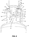
- FIG 2 there is shown a cross-sectional view of an exemplary embodiment of an adapter 28 constructed in accordance with the present invention.
- the adapter 28 of this embodiment has been pressed into the neck 30 of a bottle 32 so as to be tightly secured thereto.
- a cylindrical portion 34 having fins 36 extending outwardly therefrom to contact and be secured to the inside surface 38 of the neck 30.
- a central opening 40 to allow access by a dispenser or syringe to the medicine within the bottle 32.
- Fig. 2 there can also be seen the upper cylindrical surface 42 of the neck 30 and there is a ledge 44 formed inwardly thereof having an inner cylindrical surface 46.
- the upper flange 48 of the adapter 28 thus seats atop of the inner cylindrical surface 46 such that the upper surface 50 of the upper flange 48 is generally aligned and contiguous with the upper cylindrical surface 42, thus making it very difficult to pry the adapter 28 out of its operative position pressed into the neck 30 of bottle 32.
- the upper flange 48 is countersunk or recessed into the neck 30 of the bottle 32.
- the adapter 28 further includes an inner cylindrical portion 52 extending downwardly from the upper flange 48 in the direction toward the bottle 32.
- adapter 28 also includes a valve 53 to prevent the medicine from spilling out of the bottle 32 in case the bottle 32 is inadvertently tipped over or a child tries to access the contents by inverting the bottle 32.
- the valve 53 is comprised of a valve body 54 made of a molded material having an inner surface 56 of a diameter that fits closely over the inner cylindrical portion 52.
- An annular projection 58 is formed on the inner surface 56 of the valve body 54 that interfits into an annular depression 60 formed on the inner cylindrical portion 52 such that the valve body 54 can be readily snapped on to the inner cylindrical portion 52 in constructing the adapter 28 additionally, valve 53 may be molded directly on to adapter 28 forming a single contiguous unit.
- the lower portion of the valve body 54 is formed as a duck bill valve 61 that is normally closed but opens when an object such as a dispenser is inserted therethrough and the function and purpose of the duck bill valve 61 will later become clear.
- a dispenser 62 that is positioned within the adapter 28 just short of full penetration into the adapter 28 and, of course, into the central opening 40 and into the bottle 32.
- the dispenser 62 has a distal end 64 that is adapted to be inserted into the bottle 32 to reach the medicine therein and to withdraw the desired amount of the medicine.
- the distal end 64 is shown to be just contacting the duck bill valve 61 and further penetration into the bottle 32 allows the distal end 64 to penetrate the duck bill valve 61 to enter the bottle 32.
- the dispenser 62 also includes a cylindrical flange 66 that interfits into an enlarged cylindrical opening 68 that is larger in diameter than the central opening 40. As such, when the dispenser 62 is fully inserted into its operable position into the bottle 32, the cylindrical flange 66 seats in the enlarged cylindrical opening 68.
- a key 72 is formed on the dispenser 62 that interfits into a keyway 74 formed in the upper flange 48 of the adapter 28 such that the dispenser 62 must be accurately radially oriented to align the key 72 with the keyway 74 in order to be able to insert the dispenser 62 further into the bottle 32 so as to have the distal end 64 access the medicine.
- the dispenser 62 cannot simply be inserted into the bottle 32 but must be carefully oriented, as an adult could do, to actually have the dispenser 62 open the valve to access and remove any medicine within the bottle 32.
- the adapter 76 has a plurality of annular bumps 78 formed on the exterior of a cylindrical portion 80 that has a larger diameter than the cylindrical portion 34 of Fig. 2 such that the annular bumps 78 interfit into annular recesses 82 formed in the interior surface 84 of the neck 30 of the bottle 32. As such when the adapter 76 is pressed into the neck 30, the annular bumps 78 snap into the annular recesses 82 to positively secure the adapter 76 to the bottle 32.
- Fig. 4 there is shown a cross sectional view of a further exemplary embodiment of the present invention, again using like numbers for those previously used on corresponding components.
- the adapter 86 is a one-piece molded construction and the valve 88 is molded into the adapter 86 as a single molded piece.
- Fig. 5 there is shown a shown a cross-sectional view of a further embodiment of the present invention and, again like numbers are used to identify corresponding components described in the previous Figures.
- the adapter 94 is pressed into the neck 30 of the bottle 32 in the same manner as previously described.
- the valve 96 comprises a two piece unit, with the cylindrical portion 98 having a plurality of annular recesses 100 formed at is lower portion 102.
- a dome-shaped valve member 104 interfits into the lower portion 102 and has annular ribs 106 formed thereon that snap into the annular recesses 100 in the lower portion 102 of the valve 96.
- the dome shaped valve member 104 therefore snaps onto the lower portion 120 of the cylindrical portion 98 to securely join the two components.
- the dome shaped valve member 104 has an upper portion 108 forming a plurality of serrations 110 that, in turn, create a plurality of upper surfaces 112. Accordingly, as the distal end 64 of dispenser 62 moves downwardly, that distal end 64 contacts the upper surfaces 112 of the dome shaped valve member 104 and further downward movement causes upper portion 108 of the dome shaped valve member 104 to distort and move downwardly, thereby opening a passageway from the bottle 32 through the serrations 110 to enter the dispenser 62.
- FIG. 6 , 7 and 8 there is shown a cross-sectional view of a cap 116 constructed in accordance with the present invention, a cross-sectional view of the cap 116 of Fig 6 in the open position and a perspective view of the Fig. 6 cap 116, respectively.
- the cap 116 is comprised of a lower body 118 and an upper lid 120 that is movable between a closed position and an open position as will be later explained.
- the lower body 118 has an outer cylindrical portion 122 the surrounds the neck 124 of the bottle 126.
- the lower body 118 includes an inner cylindrical portion 132 having a plurality of annular recesses 134 formed at its lower portion 136.
- a dome-shaped valve member 138 interfits into the lower portion 136 and has annular ribs 140 formed thereon that snap into the annular recesses 134 in the lower portion 136 of the lower body 118.
- the dome shaped valve member 138 therefore snaps onto the lower portion 136 of the inner cylindrical portion 132 to securely join the two components.
- the dome shaped valve member 138 has an upper portion 142 forming a plurality of serrations 144 that, in turn, create a plurality of upper surfaces 146. Accordingly, as the distal end 145 of the dispenser 143 moves downwardly, that distal end 145 contacts the upper surfaces 146 of the dome shaped valve member 138 and further downward movement causes upper portion 142 of the dome shaped valve member 138 to distort and move downwardly, thereby opening a passageway from the bottle 126 through the serrations 144 to enter the dispenser 143 in the same manner as described with respect to Fig. 5 .
- the lower body 118 also includes a central opening 148 that receives the dispenser 143 in accessing the medicine within the bottle 126. There is also a pair of upward latches 150 provided on the lower body 118 that extend upwardly and serve a purpose to be later explained.
- the upper lid 120 is hingedly affixed to the lower body 118 and in the exemplary embodiment that hinged connection can be by means of a living hinge 152.
- the upper lid 120 has a closed position as shown in Fig. 6 and an open position as shown in Fig. 7 .
- the upper lid 120 in the closed position of Fig. 6 , includes a downwardly extending plug 154 that interfits into and closes the central opening 148.
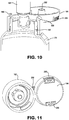
- FIG. 9 a cross-sectional view of a cap 160 constructed in accordance with the present invention
- a cross-sectional view of the cap 160 of Fig. 9 in the open position and a perspective view of the Fig. 9 cap 160, respectively.
- the cap 160 is comprised of a lower body 162 and an upper lid 164 that is movable between a closed position and an open position as will be later explained.
- the lower body 162 has an outer cylindrical portion 166 that surrounds the neck 168 of the bottle 170.
- a fin 171 formed on the lower body 162 the interfits with a projection 172 provided on the neck 168 of the bottle 170 such that the lower body 162 can be easily snapped onto the bottle neck 168 to securely assemble the cap 160 to the bottle 170.
- the lower body 162 includes an inner cylindrical portion 174 having an annular recesses 176 formed at is lower portion 178.
- a valve 180 is located in the lower portion 178 of the inner cylindrical portion 174 and is comprised of a valve body 184 made of a molded material having an inner surface 186 of a diameter that fits closely over the inner cylindrical portion 174.
- An annular projection 188 is formed on the inner surface of the valve body 184 that interfits into the annular recess 176 formed on the inner cylindrical portion 174 such that the valve body 184 can be readily snapped on to the inner cylindrical portion 174 in constructing the cap 160.
- the lower portion of the valve body 184 is formed as a duck bill valve 192 that is normally closed but opens when an object is inserted therethrough and the function and purpose of the duck bill valve 192 is the same as that discussed with respect to Fig. 2 as will be appreciated buy those skilled in the art, the present invention is not limited to the use of duckbill valves as other valve configurations and shapes maybe used without departing form the spirit of the invention.
- the lower body 162 also includes a central opening 194 that receives a dispenser or syringe 196 in accessing the medicine within the bottle 170. Again, as with the embodiment of Figs. 6-8 , there is a pair of upward latches 198 provided on the lower body 162 that extend upwardly
- the upper lid 164 is hingedly affixed to the lower body 162 and in the exemplary embodiment that hinged connection can be by means of a living hinge 200.
- the upper lid 164 has a closed position as shown in Fig 9 and an open position as shown in Fig 10 .
- the upper lid 164 includes a downwardly extending plug 202 that interfits into and closes the central opening 194.
- the adapter 210 has an annular bump 212 formed on the exterior of a cylindrical portion 213 that has a larger diameter than the cylindrical portion 34 of Fig. 2 such that the annular bump 212 interfits into annular recesses 211 formed in the interior surface 84 of the neck 30 of the bottle 32. As such when the adapter 210 is pressed into the neck 30, the annular bump 212 snaps into the annular recesses 211 to positively secure the adapter 210 to the bottle 32.
- the adapter 210 further includes an inner cylindrical portion 214 extending downwardly from the upper flange 48 in the direction toward the bottle 32.
- Cylindrical portion 214 has a inwardly sloping bottom portion 215 that narrows central opening 40 to orifice 216.
- dispenser 62 can be inserted completely into cylindrical portion 214. In this position, distal end 64 contacts bottom portion 215 and medicine from bottle 32 can be dispensed through orifice 216 into dispenser 62.
- the reduction in the diameter of central opening 40 down to the diameter of orifice 216 severely limits and greatly reduces access to the medicine within bottle 32.
Landscapes
- Health & Medical Sciences (AREA)
- Engineering & Computer Science (AREA)
- Mechanical Engineering (AREA)
- Pharmacology & Pharmacy (AREA)
- Life Sciences & Earth Sciences (AREA)
- Animal Behavior & Ethology (AREA)
- General Health & Medical Sciences (AREA)
- Public Health (AREA)
- Veterinary Medicine (AREA)
- Closures For Containers (AREA)
- Medical Preparation Storing Or Oral Administration Devices (AREA)
Description
- The present invention relates to adapters that are pressed into the open end of a bottle neck to allow the use of a dispenser such as a syringe with a bottle, and, more particularly, to a press in adapter that can be pressed into the open end of a bottle which restricts leakage from the bottle and resists removal from the bottle.
- There are, today, bottle adapters that are used for children's medications and allows a bottle to be accessed by a syringe so that the caregiver can administer that dosage of the medicine to the child. Basically, the adapter is located at the top of the bottle neck to create a syringe accessibility to that bottle. They are pressed into the open top of the bottle to make assembly relatively cost effective and have a central opening through which a dispenser or syringe can be inserted to reach and withdraw the medicine from the bottle.
- With the present adapters, however, there are some problems, in that children can bypass the adapter and access the content of the bottle, either by effecting some bypass method or by the removal of the adapter in its entirety. It is estimated that about 180,000 children each year are seen for medication overdoses and the main issue in such overdoses is the unsupervised ingestion of the medicine.
- For example, one issue with existing adapters is that the central opening can be used by a child to access the medicine by inverting the bottle and shaking, sucking or otherwise manipulating the bottle to access the medicine. There is, also the possibility that the bottle may be overturned, either deliberately or inadvertently, and the contents leak out of that central opening.
- Another problem with the present adapters, is that there is an upper flange that sits atop the upper edge of the neck of the bottle such that a child, or other person can insert a tool, fingernail, or even teeth to pry the adapter out of the bottle neck and thus expose the medicine to a child.
- It would therefore be advantageous to have an improved bottle adapted that can be pressed into the bottle and which provides enhanced protection against access to the content of the bottle by persons, such as children.
-
EP 0 138 681 A2 describes an assembly for preparing and dispensing a solution and the stopper for such an assembly, said assembly comprising a first bottle containing a first liquid component, with an elongated head; a second bottle containing a second component, liquid or solid; a stopper for this second bottle presenting a recess, whose shape is homologous of the head of the first bottle, and in which said head is for example screwed. The bottom of the recess is constituted by a membrane of deformable material comprising an axial orifice which is hermetically closed, in the absence of deformation of the membrane, by the natural radial constriction of the material of the membrane. By screwing the first bottle in the stopper, the membrane is axially deformed and the orifice is radially distended, thus allowing the two bottles to be placed in communication in reversible manner. This document also describes a process for making the stopper. - The present invention provides a system for removing the contents of a bottle, as set out in claim 1.
- The present invention further provides a method for removing the contents of a bottle, as set out in claim 9.
-
-
Fig. 1 is a cross-sectional view of a conventional bottle adapter in its operative position interfitted into the top of a bottle; -
Fig. 2 is a cross-sectional view of an exemplary embodiment of a bottle adapter of the present invention in its operative position interfitted into the top of a bottle; -
Fig. 3 is a cross-sectional view of an alternative embodiment of a bottle adapter of the present invention in its operative position interfitted into the top of a bottle; -
Fig. 4 is a cross-sectional view of a further alternative embodiment of a bottle adapter of the present invention in its operative position interfitted into the top of a bottle; -
Fig. 5 is a cross-sectional view of a still further alternative embodiment of a bottle adapter of the present invention in its operative position interfitted into the top of a bottle; -
Fig. 6 is a cross-sectional view of a cap with its upper lid in the closed position closing the top of a bottle; -
Fig. 7 is a cross-sectional view of the cap ofFig 6 with the upper lid in the open position; -
Fig. 8 is a perspective view of the cap ofFig 6 ; -
Fig. 9 is a is a cross-sectional view of an other embodiment of a cap of the present invention with its upper lid in the closed position closing the top of a bottle; -
Fig 10 is a cross-sectional view of the cap ofFig 9 with the upper lid in the open position; -
Fig 11 is a perspective view of the cap ofFig 9 and -
Fig. 12 is a cross-sectional view of a further embodiment of a bottle adapter of the present invention in its operative position interfitted into the top of a bottle; - As described below, an embodiment of the present invention overcomes the difficulties heretofore encountered with present press in bottle adapters. With the present invention, the adapter has a valve located at its distal end that resides within the neck of the bottle. The valve prevents the spillage of medicine from the bottle if the bottle is inadvertently overturned or there is a deliberate attempt by a child to gain access to the medicine within the bottle. As will be appreciated by those skilled in the art, the valve can be of different constructions and is not limited to the specific configurations disclosed.
- The valve may be a two piece construction. In this example, the adapter has a two-piece valve, such as a duck bill valve at its distal end that is snapped or molded on to the adapter. The valve is opened as the dispenser or syringe penetrates the duck bill valve so that access can be gained by the dispenser or syringe to the medicine within the bottle.
- Alternatively, the valve can be constructed as a unitary adapter such that the adapter and valve are molded together in a one-piece design.
- In another example, the valve has a dome-shaped valve member that is flexible and is distorted by the dispenser or syringe as it is introduced into the bottle. The dome shaped member flexes inwardly by the advancement of the distal end of the dispenser or syringe to open a passageway for the dispenser or syringe to access the medicine within the bottle.
- As a advantageous feature, the adapters described below, have an upper flange that is recessed or countersunk with the top of the neck of the bottle so that it is considerably difficult to gain access to the underside of the upper flange to pry the adapter out of the neck of the bottle to gain access to the medicine.
- There is further described a molded cap that is adapted to be affixed to the neck of a bottle. The cap has a lower body and an upper lid that is hingedly affixed to the lower body, such as by the use of a living hinge. The upper lid can then be moved between a closed position where the central opening in the cap is closed and an upper position where the central opening is open and accessible by a syringe. There is a locking system that locks the upper lid in its closed position and the locking system requires a deliberate action by the user to open the upper lid to gain access to the medicine within the bottle.
- With the cap covering the neck of the bottle, there is a valve at the distal end of the cap that extends into the bottle and the valve can be opened by the physical insertion of a dispenser or syringe in the manner described with respect to the adapters.
- In another example, the adapter does not utilize a valve at the distal end, but instead relies on a reduced opening in conjunction with the other features disclosed to restrict the inadvertent or unintentional flow of fluid from the bottle.
- These and other features and their advantages will become more readily apparent during the following detailed description taken in conjunction with the drawings herein.
- Referring now to
Fig. 1 , there is shown a cross-sectional view of aconventional bottle adapter 10 currently being used commercially. As can be seen, thebottle 12 has anupstanding neck 14 having an upper,cylindrical surface 16. Theadapter 10 includes a plurality offins 18 that extend outwardly from acylindrical portion 20 of theadapter 10 and press against theinside surface 22 of theneck 14 to retain theadapter 10 firmly in position after being pressed into theneck 14 of thebottle 12. - The
adapter 10 has anupper flange 24 that closes theneck 14 of thebottle 12 and which has acentral opening 26 through which a syringe can be inserted in gaining access to the medicine that is contained within thebottle 12. - Accordingly, there is a disadvantage with the
conventional adapter 10 ofFig. 1 since theupper flange 24 overlaps the uppercylindrical surface 16 of theneck 14 and, therefore, present an opportunity for someone, such as a child, to pry theadapter 10 out of thebottle 12 by inserting a tool, fingernail, or by use of teeth between theupper flange 24 and the uppercylindrical surface 16 of the bottle. - Turning now to
Fig 2 , there is shown a cross-sectional view of an exemplary embodiment of anadapter 28 constructed in accordance with the present invention. As can be seen, theadapter 28 of this embodiment has been pressed into theneck 30 of abottle 32 so as to be tightly secured thereto. Again, there is acylindrical portion 34 havingfins 36 extending outwardly therefrom to contact and be secured to theinside surface 38 of theneck 30. There is acentral opening 40 to allow access by a dispenser or syringe to the medicine within thebottle 32. - In
Fig. 2 , there can also be seen the uppercylindrical surface 42 of theneck 30 and there is aledge 44 formed inwardly thereof having an innercylindrical surface 46. In the interfitting of theadapter 28 to thebottle 32, theupper flange 48 of theadapter 28 thus seats atop of the innercylindrical surface 46 such that theupper surface 50 of theupper flange 48 is generally aligned and contiguous with the uppercylindrical surface 42, thus making it very difficult to pry theadapter 28 out of its operative position pressed into theneck 30 ofbottle 32. In effect, theupper flange 48 is countersunk or recessed into theneck 30 of thebottle 32. Theadapter 28 further includes an innercylindrical portion 52 extending downwardly from theupper flange 48 in the direction toward thebottle 32. - In this embodiment,
adapter 28 also includes avalve 53 to prevent the medicine from spilling out of thebottle 32 in case thebottle 32 is inadvertently tipped over or a child tries to access the contents by inverting thebottle 32. Thevalve 53 is comprised of avalve body 54 made of a molded material having aninner surface 56 of a diameter that fits closely over the innercylindrical portion 52. Anannular projection 58 is formed on theinner surface 56 of thevalve body 54 that interfits into anannular depression 60 formed on the innercylindrical portion 52 such that thevalve body 54 can be readily snapped on to the innercylindrical portion 52 in constructing theadapter 28 additionally,valve 53 may be molded directly on toadapter 28 forming a single contiguous unit. - The lower portion of the
valve body 54 is formed as aduck bill valve 61 that is normally closed but opens when an object such as a dispenser is inserted therethrough and the function and purpose of theduck bill valve 61 will later become clear. - As also can be seen in
Fig. 2 , there is adispenser 62 that is positioned within theadapter 28 just short of full penetration into theadapter 28 and, of course, into thecentral opening 40 and into thebottle 32. Thedispenser 62 has adistal end 64 that is adapted to be inserted into thebottle 32 to reach the medicine therein and to withdraw the desired amount of the medicine. In the position ofFig. 2 , thedistal end 64 is shown to be just contacting theduck bill valve 61 and further penetration into thebottle 32 allows thedistal end 64 to penetrate theduck bill valve 61 to enter thebottle 32. - The
dispenser 62 also includes acylindrical flange 66 that interfits into an enlargedcylindrical opening 68 that is larger in diameter than thecentral opening 40. As such, when thedispenser 62 is fully inserted into its operable position into thebottle 32, thecylindrical flange 66 seats in the enlargedcylindrical opening 68. - A key 72 is formed on the
dispenser 62 that interfits into akeyway 74 formed in theupper flange 48 of theadapter 28 such that thedispenser 62 must be accurately radially oriented to align the key 72 with thekeyway 74 in order to be able to insert thedispenser 62 further into thebottle 32 so as to have thedistal end 64 access the medicine. Thus, thedispenser 62 cannot simply be inserted into thebottle 32 but must be carefully oriented, as an adult could do, to actually have thedispenser 62 open the valve to access and remove any medicine within thebottle 32. - Turning now to
Fig. 3 , there is shown a cross-sectional view of a further embodiment of the present invention where like identification numbers are used on the same components described and explained with respect toFig. 2 . In this embodiment, theadapter 76 has a plurality ofannular bumps 78 formed on the exterior of acylindrical portion 80 that has a larger diameter than thecylindrical portion 34 ofFig. 2 such that theannular bumps 78 interfit intoannular recesses 82 formed in theinterior surface 84 of theneck 30 of thebottle 32. As such when theadapter 76 is pressed into theneck 30, theannular bumps 78 snap into theannular recesses 82 to positively secure theadapter 76 to thebottle 32. - Turning now to
Fig. 4 , there is shown a cross sectional view of a further exemplary embodiment of the present invention, again using like numbers for those previously used on corresponding components. In this embodiment, however, theadapter 86 is a one-piece molded construction and thevalve 88 is molded into theadapter 86 as a single molded piece. - Turning now to
Fig. 5 , there is shown a shown a cross-sectional view of a further embodiment of the present invention and, again like numbers are used to identify corresponding components described in the previous Figures. In this embodiment, theadapter 94 is pressed into theneck 30 of thebottle 32 in the same manner as previously described. With this embodiment, however, thevalve 96 comprises a two piece unit, with thecylindrical portion 98 having a plurality ofannular recesses 100 formed at islower portion 102. A dome-shapedvalve member 104 interfits into thelower portion 102 and hasannular ribs 106 formed thereon that snap into theannular recesses 100 in thelower portion 102 of thevalve 96. The dome shapedvalve member 104 therefore snaps onto thelower portion 120 of thecylindrical portion 98 to securely join the two components. - The dome shaped
valve member 104 has anupper portion 108 forming a plurality ofserrations 110 that, in turn, create a plurality ofupper surfaces 112. Accordingly, as thedistal end 64 ofdispenser 62 moves downwardly, thatdistal end 64 contacts theupper surfaces 112 of the dome shapedvalve member 104 and further downward movement causesupper portion 108 of the dome shapedvalve member 104 to distort and move downwardly, thereby opening a passageway from thebottle 32 through theserrations 110 to enter thedispenser 62. - Turning now to
Figs 6 ,7 and 8 , there is shown a cross-sectional view of acap 116 constructed in accordance with the present invention, a cross-sectional view of thecap 116 ofFig 6 in the open position and a perspective view of theFig. 6 cap 116, respectively. - Accordingly, as can be seen in
Figs. 6-8 , thecap 116 is comprised of alower body 118 and anupper lid 120 that is movable between a closed position and an open position as will be later explained. In this embodiment, thelower body 118 has an outercylindrical portion 122 the surrounds theneck 124 of thebottle 126. There is aindention 128 formed in thelower body 118 that interfits with aprojection 130 provided on theneck 124 of thebottle 126 such that thelower body 118 can be easily snapped onto thebottle neck 124 to securely assemble thecap 116 to thebottle 126. - As can also be seen, the
lower body 118 includes an innercylindrical portion 132 having a plurality ofannular recesses 134 formed at itslower portion 136. A dome-shapedvalve member 138 interfits into thelower portion 136 and hasannular ribs 140 formed thereon that snap into theannular recesses 134 in thelower portion 136 of thelower body 118. The dome shapedvalve member 138 therefore snaps onto thelower portion 136 of the innercylindrical portion 132 to securely join the two components. - The dome shaped
valve member 138 has anupper portion 142 forming a plurality ofserrations 144 that, in turn, create a plurality ofupper surfaces 146. Accordingly, as thedistal end 145 of thedispenser 143 moves downwardly, thatdistal end 145 contacts theupper surfaces 146 of the dome shapedvalve member 138 and further downward movement causesupper portion 142 of the dome shapedvalve member 138 to distort and move downwardly, thereby opening a passageway from thebottle 126 through theserrations 144 to enter thedispenser 143 in the same manner as described with respect toFig. 5 . - The
lower body 118 also includes acentral opening 148 that receives thedispenser 143 in accessing the medicine within thebottle 126. There is also a pair ofupward latches 150 provided on thelower body 118 that extend upwardly and serve a purpose to be later explained. - Taking then, the
upper lid 120, theupper lid 120 is hingedly affixed to thelower body 118 and in the exemplary embodiment that hinged connection can be by means of aliving hinge 152. Theupper lid 120 has a closed position as shown inFig. 6 and an open position as shown inFig. 7 . As can be seen, in the closed position ofFig. 6 , theupper lid 120 includes a downwardly extendingplug 154 that interfits into and closes thecentral opening 148. - Also, in the closed position of
Fig. 6 , there aredownward latches 156 that latch with theupward latches 150 of thelower body 118 to retain theupper lid 120 in its closed position. In order to move theupper lid 120 from its latched, closed position ofFig. 6 to its open position ofFig. 7 , there arerelease buttons 158 formed in theupper lid 120 that are adapted to be pressed inwardly so as to move the downward latches 156 inwardly to disengage from theupward latches 150, thereby releasing theupper lid 120 from its latched, closed position so that theupper lid 120 can readily be moved to its open position. - Turning now to
Figs. 9 ,10 and 11 , there is shown a cross-sectional view of acap 160 constructed in accordance with the present invention, a cross-sectional view of thecap 160 ofFig. 9 in the open position and a perspective view of theFig. 9 cap 160, respectively. - Accordingly, as can be seen in
Figs. 9-11 , thecap 160 is comprised of alower body 162 and anupper lid 164 that is movable between a closed position and an open position as will be later explained. In this embodiment, thelower body 162 has an outercylindrical portion 166 that surrounds theneck 168 of thebottle 170. There is afin 171 formed on thelower body 162 the interfits with aprojection 172 provided on theneck 168 of thebottle 170 such that thelower body 162 can be easily snapped onto thebottle neck 168 to securely assemble thecap 160 to thebottle 170. - As can also be seen, the
lower body 162 includes an innercylindrical portion 174 having anannular recesses 176 formed at islower portion 178. Avalve 180 is located in thelower portion 178 of the innercylindrical portion 174 and is comprised of avalve body 184 made of a molded material having aninner surface 186 of a diameter that fits closely over the innercylindrical portion 174. Anannular projection 188 is formed on the inner surface of thevalve body 184 that interfits into theannular recess 176 formed on the innercylindrical portion 174 such that thevalve body 184 can be readily snapped on to the innercylindrical portion 174 in constructing thecap 160. - The lower portion of the
valve body 184 is formed as aduck bill valve 192 that is normally closed but opens when an object is inserted therethrough and the function and purpose of theduck bill valve 192 is the same as that discussed with respect toFig. 2 as will be appreciated buy those skilled in the art, the present invention is not limited to the use of duckbill valves as other valve configurations and shapes maybe used without departing form the spirit of the invention. - The
lower body 162 also includes acentral opening 194 that receives a dispenser orsyringe 196 in accessing the medicine within thebottle 170. Again, as with the embodiment ofFigs. 6-8 , there is a pair ofupward latches 198 provided on thelower body 162 that extend upwardly - Again the
upper lid 164 is hingedly affixed to thelower body 162 and in the exemplary embodiment that hinged connection can be by means of aliving hinge 200. Theupper lid 164 has a closed position as shown inFig 9 and an open position as shown inFig 10 . As can be seen in the closed position ofFig. 9 , theupper lid 164 includes a downwardly extendingplug 202 that interfits into and closes thecentral opening 194. - Also, in the closed position of
Fig. 9 , there aredownward latches 204 that latch with theupward latches 198 of thelower body 162 to retain theupper lid 164 in its closed position. In order to move theupper lid 164 from its latched, closed position ofFig. 9 to its open position ofFig. 10 , there arerelease buttons 206 formed in theupper lid 164 that are adapted to be pressed inwardly so as to move the downward latches 204 inwardly to disengage from theupward latches 198, thereby releasing theupper lid 164 from its latched, closed position so that theupper lid 164 can readily be moved to its open position. - Turning now to
Fig. 12 , there is shown a cross-sectional view of a further embodiment of the present invention where like identification numbers are used on the same components described and explained with respect toFigs. 2 and3 . In this embodiment, theadapter 210 has anannular bump 212 formed on the exterior of acylindrical portion 213 that has a larger diameter than thecylindrical portion 34 ofFig. 2 such that theannular bump 212 interfits intoannular recesses 211 formed in theinterior surface 84 of theneck 30 of thebottle 32. As such when theadapter 210 is pressed into theneck 30, theannular bump 212 snaps into theannular recesses 211 to positively secure theadapter 210 to thebottle 32. Theadapter 210 further includes an innercylindrical portion 214 extending downwardly from theupper flange 48 in the direction toward thebottle 32.Cylindrical portion 214 has a inwardly slopingbottom portion 215 that narrowscentral opening 40 toorifice 216. In this embodiment, when key 72 ondispenser 62 is properly aligned withkeyway 74,dispenser 62 can be inserted completely intocylindrical portion 214. In this position,distal end 64 contactsbottom portion 215 and medicine frombottle 32 can be dispensed throughorifice 216 intodispenser 62. The reduction in the diameter ofcentral opening 40 down to the diameter oforifice 216 severely limits and greatly reduces access to the medicine withinbottle 32. - Those skilled in the art will readily recognize numerous adaptations and modifications which can be made to the pressed in bottle adapter, bottle and dispenser of the present invention which will result in an improved adapter, bottle and dispenser, yet all of which will fall within the scope of the present invention as defined in the following claims.
Claims (10)
- A system for removing the contents of a bottle (32), the system comprising:a bottle (32) having a neck (30) forming an internal surface,an adapter (28, 86, 76) interfitted into the bottle (32) and having a seal against the internal surface, said adapter (28, 86, 76) having a central opening extending therethrough and a distal end extending into the neck (30) and a normally closed valve (53, 88) located proximate the distal end of the adapter (28, 86, 76) closing the central opening, anda dispenser (62) including a barrel portion and a narrow tip portion at a distal end (64), said narrowed tip portion adapted to be inserted into the central opening of the adapter (28, 86, 76), said tip portion being dimensioned so as to penetrate no further than a predetermined distance into the bottle (32) to contact and open the normally closed valve (53, 88) to open said central opening for removal of the contents of the bottle (32),wherein said barrel portion is larger in diameter than the central opening so as to remain outside the bottle (32) and only the narrowed tip portion penetrates the bottle (32) to the predetermined distance,wherein, when penetrating the bottle (32) to the predetermined distance, the narrowed tip portion enters an interior cavity of the normally closed valve (53, 88) to open the valve (53, 88).
- The system of claim 1 further comprising a keying system that selectively prevents the narrowed tip portion of the dispenser (62) from penetrating the predetermined distance into the bottle (32) .
- The system of claim 2 wherein the keying system prevents the penetration of the narrowed tip portion of the dispenser (62) the predetermined distance into the bottle unless the dispenser (62) is in a predetermined radial orientation with respect to the adapter (28, 86, 76).
- The system of claim 2 wherein the keying system comprises a key (72) formed on the tip portion of the dispenser (62) and a keyway (74) formed in the adapter (28, 86, 76) and wherein the key must align and enter into the keyway (74) to allow the tip portion of the dispenser (62) to penetrate the predetermined distance into the bottle (32).
- The system of claim 1, wherein an internal surface of a neck (30) of the bottle (32) has at least one annular recess (82) and the adapter (76) has an external surface having at least one annular bump (78) adapted to interfit into the at least one annular recess (82).
- The system of claim 1 wherein the normally closed valve (53, 88) is integrally molded to the adapter (86).
- The system of claim 1 wherein the normally closed valve (53, 88) is a duck bill valve (61).
- The system of claim 1 wherein the external surface of the adapter (76) comprises a plurality of annular bumps (78) that seal against an internal surface of a neck (30).
- A method of removing the contents of a bottle (32) comprising the steps of:providing a bottle (32) having a neck (30) forming an internal surface, the bottle (32) having an adapter (28, 86, 78) interfitted into the bottle (32) and sealed against the internal surface, said adapter (28, 86, 78) having a central opening extending therethrough and a distal end extending into the neck (30), a normally closed valve (53, 88) located proximate the distal end of the adapter closing the central opening, the adapter having a keyway (74) formed therein,providing a dispenser (62), the dispenser including a barrel portion and a narrow tip portion at a distal end (64), the narrow tip portion having a key (72) formed thereon;radially aligning the key (72) on the narrow tip portion of the dispenser (62) with the keyway (74) formed on the adapter (28, 86, 78); andinserting the narrow tip portion of the dispenser (62) into the bottle (32) with the key (72) entering the keyway (74) to a predetermined depth defined by an interior surface of the keyway,whereby the narrow tip portion of the dispenser (62) enters an interior cavity of the normally closed valve (53, 88) to open the valve.
- The method of claim 9 wherein the step of aligning comprises rotating the dispenser (62) radially to align the key (72) with the keyway (74).
Priority Applications (1)
| Application Number | Priority Date | Filing Date | Title |
|---|---|---|---|
| EP17187698.0A EP3266437A1 (en) | 2009-06-30 | 2010-06-30 | Press in bottle adapter |
Applications Claiming Priority (2)
| Application Number | Priority Date | Filing Date | Title |
|---|---|---|---|
| US22172809P | 2009-06-30 | 2009-06-30 | |
| PCT/US2010/040614 WO2011002893A1 (en) | 2009-06-30 | 2010-06-30 | Press in bottle adapter |
Related Child Applications (2)
| Application Number | Title | Priority Date | Filing Date |
|---|---|---|---|
| EP17187698.0A Division EP3266437A1 (en) | 2009-06-30 | 2010-06-30 | Press in bottle adapter |
| EP17187698.0A Division-Into EP3266437A1 (en) | 2009-06-30 | 2010-06-30 | Press in bottle adapter |
Publications (3)
| Publication Number | Publication Date |
|---|---|
| EP2461784A1 EP2461784A1 (en) | 2012-06-13 |
| EP2461784A4 EP2461784A4 (en) | 2017-02-22 |
| EP2461784B1 true EP2461784B1 (en) | 2018-05-09 |
Family
ID=43379605
Family Applications (2)
| Application Number | Title | Priority Date | Filing Date |
|---|---|---|---|
| EP17187698.0A Withdrawn EP3266437A1 (en) | 2009-06-30 | 2010-06-30 | Press in bottle adapter |
| EP10794709.5A Active EP2461784B1 (en) | 2009-06-30 | 2010-06-30 | Press in bottle adapter |
Family Applications Before (1)
| Application Number | Title | Priority Date | Filing Date |
|---|---|---|---|
| EP17187698.0A Withdrawn EP3266437A1 (en) | 2009-06-30 | 2010-06-30 | Press in bottle adapter |
Country Status (4)
| Country | Link |
|---|---|
| US (1) | US8459312B2 (en) |
| EP (2) | EP3266437A1 (en) |
| CA (1) | CA2764895C (en) |
| WO (1) | WO2011002893A1 (en) |
Families Citing this family (42)
| Publication number | Priority date | Publication date | Assignee | Title |
|---|---|---|---|---|
| US20110130740A1 (en) * | 1998-03-06 | 2011-06-02 | Abner Levy | Medication Bottle for Use with Oral Syringe |
| US9296531B2 (en) * | 2010-01-12 | 2016-03-29 | Medela Holding Ag | Container with sealed cap and venting system |
| US20120216909A1 (en) * | 2010-11-01 | 2012-08-30 | Abner Levy | Dosing Adapter for Use with Oral Syringe |
| ITPR20110045A1 (en) * | 2011-05-30 | 2012-12-01 | Bormioli Rocco & Figlio Spa | ADAPTER. |
| US8485231B2 (en) | 2011-07-11 | 2013-07-16 | Tessy Plastics Corporation | Method and apparatus for dispensing liquid medicine |
| US8931522B2 (en) * | 2011-08-16 | 2015-01-13 | Glenn B. Paige | Fill cap for a drink container |
| US8870004B2 (en) | 2011-10-25 | 2014-10-28 | Target Brands, Inc. | Pharmacy bottle, system, and method |
| US8758322B2 (en) | 2011-10-25 | 2014-06-24 | Target Brands, Inc. | Dispensing insert for a medicine containment and dispensing system and associated method |
| US9156569B2 (en) * | 2011-12-21 | 2015-10-13 | Berry Plastics Corporation | Pediatric dosing dispenser |
| US9849067B2 (en) | 2011-12-21 | 2017-12-26 | Berry Plastics Corporation | Pediatric dosing dispenser |
| US8783486B1 (en) * | 2012-03-09 | 2014-07-22 | Chase H. Hoyt | Bottle stopper for evacuation pump |
| WO2014012066A2 (en) | 2012-07-13 | 2014-01-16 | Comar, Inc. | Upwardly biasing child-resistant closure for liquid medicaments |
| FR2995290B1 (en) * | 2012-09-13 | 2014-09-26 | Rexam Dispensing Sys | FILLABLE VIAL FOR DISPENSING A FLUID PRODUCT |
| EP2719420A1 (en) * | 2012-10-12 | 2014-04-16 | Becton Dickinson France | Adaptor for a drug delivery device and method for mounting said adaptor thereon |
| FR2996828B1 (en) * | 2012-10-15 | 2014-10-24 | Rexam Dispensing Sys | FILLABLE VIAL FOR DISPENSING A FLUID PRODUCT |
| FR2996829B1 (en) * | 2012-10-15 | 2014-10-24 | Rexam Dispensing Sys | FILLABLE VIAL FOR DISPENSING A FLUID PRODUCT |
| MX2012013347A (en) * | 2012-11-16 | 2013-10-08 | Leopoldo Meneses Fernandez | System for dispensing drugs. |
| US20170028131A1 (en) * | 2013-03-07 | 2017-02-02 | Nicholas J Perazzo | Push-pull medication container adapter cap for enteral syringe filling systems |
| US9763854B2 (en) | 2015-05-20 | 2017-09-19 | L. Perrigo Company | Flow restrictor |
| AT517242B1 (en) * | 2015-06-11 | 2019-05-15 | Innveri Ag | Device for preserving beverages |
| GB201512640D0 (en) * | 2015-07-17 | 2015-08-26 | Obrist Closures Switzerland | Improvements in or relating to closures |
| GB2546755A (en) * | 2016-01-26 | 2017-08-02 | Gobubl Ltd | Vessel cap |
| US11166876B2 (en) | 2016-02-24 | 2021-11-09 | Neomed, Inc. | Fluid transfer connector |
| US12447112B2 (en) | 2016-02-24 | 2025-10-21 | Avent, Inc. | Fluid transfer connector |
| WO2017147233A2 (en) | 2016-02-24 | 2017-08-31 | Neomed, Inc. | Fluid transfer connector |
| US10058481B1 (en) | 2016-06-25 | 2018-08-28 | Ronald D. Russo | Safety sealed bottle stopper |
| US20180050183A1 (en) * | 2016-08-17 | 2018-02-22 | Kristine Marie Taylor | Internal bottle adapter for material transfer |
| USD908212S1 (en) | 2016-08-17 | 2021-01-19 | Kristine Marie Taylor | Adapter |
| GB2560693B (en) * | 2017-02-01 | 2019-11-20 | Nerudia Ltd | Valve assembly and dispenser |
| US11383900B2 (en) | 2019-03-01 | 2022-07-12 | Berry Global, Inc. | Pediatric dosing dispenser |
| WO2020180791A1 (en) | 2019-03-01 | 2020-09-10 | Berry Global, Inc. | Pediatric dosing dispenser |
| WO2020190490A1 (en) | 2019-03-15 | 2020-09-24 | Berry Global, Inc. | Pediatric dosing dispenser |
| JP6892564B1 (en) * | 2019-08-26 | 2021-06-23 | 株式会社メニコン | Eye device case and refill container used for the eye device case |
| CN113804845B (en) * | 2020-06-11 | 2024-03-15 | 力合科技(湖南)股份有限公司 | Water quality on-line monitoring sampling device |
| AU2021349207B2 (en) * | 2020-09-28 | 2024-07-11 | Boston Scientific Scimed, Inc. | Universal fluid container enclosure systems |
| WO2022271578A1 (en) * | 2021-06-21 | 2022-12-29 | Vertice Pharma Llc | Adapter for clinical, medical and laboratory containers |
| CN121291933A (en) | 2021-09-01 | 2026-01-09 | 贝里国际公司 | Packaging for storing and distributing fluids |
| US11903902B2 (en) | 2022-01-03 | 2024-02-20 | Benjamin Martin DAVIS | Fluid transfer couplings |
| USD975543S1 (en) * | 2022-01-28 | 2023-01-17 | Qingzhi Li | Bottle adapter |
| CN114948726B (en) * | 2022-07-29 | 2022-11-15 | 上海奥科达生物医药科技有限公司 | Liquid preparation multiple administration system |
| US12403244B2 (en) | 2023-05-18 | 2025-09-02 | Adavation Llc | Syringe infusion pump |
| US12582812B2 (en) | 2023-11-22 | 2026-03-24 | Adavation Llc | Selectably locking medical coupling |
Family Cites Families (17)
| Publication number | Priority date | Publication date | Assignee | Title |
|---|---|---|---|---|
| US2290348A (en) * | 1940-03-06 | 1942-07-21 | Gen Motors Corp | Container |
| US2783908A (en) * | 1953-02-13 | 1957-03-05 | Glaxo Lab Ltd | Closures for bottles, vials and the like |
| US4220248A (en) * | 1978-10-31 | 1980-09-02 | Polytop Corporation | Closure with hinged lid and cam and spring elements holding lid open or closed |
| ES266599Y (en) * | 1982-06-18 | 1983-11-16 | "DEVICE APPLICABLE TO THE CONDUCT OF ANALYSIS". | |
| US5688254A (en) | 1983-01-24 | 1997-11-18 | Icu Medical, Inc. | Medical connector |
| FR2552404B1 (en) * | 1983-09-26 | 1987-12-24 | Merck Sharp & Dohme | ASSEMBLY FOR PREPARING AND DELIVERING A SOLUTION, SHUTTERING PLUG FOR SUCH ASSEMBLY AND METHOD FOR MANUFACTURING THE SAME |
| DE69001491T2 (en) * | 1989-02-03 | 1993-08-12 | Glaxo Group Ltd | CLOSURE. |
| US4917253A (en) * | 1989-03-30 | 1990-04-17 | Continental Plastics, Inc. | Container-closure with fold over projections |
| US5088612A (en) | 1991-06-10 | 1992-02-18 | Comar, Inc. | Vial cap |
| US5429256A (en) * | 1994-01-24 | 1995-07-04 | Kestenbaum; Alan D. | Drug withdrawal system for container |
| US5620434A (en) | 1994-03-14 | 1997-04-15 | Brony; Seth K. | Medicine vial link for needleless syringes |
| US5931828A (en) * | 1996-09-04 | 1999-08-03 | The West Company, Incorporated | Reclosable vial closure |
| US5921419A (en) * | 1998-05-04 | 1999-07-13 | Bracco Research Usa | Universal stopper |
| GB0013690D0 (en) * | 2000-06-06 | 2000-07-26 | Advanced Biotech Ltd | Improved closure |
| WO2002085429A2 (en) | 2001-04-24 | 2002-10-31 | Comar | Child friendly syringe |
| NL1022901C2 (en) * | 2003-03-12 | 2004-09-14 | Marita De Beer Holding B V | Shutter and methods for placing or removing such a shutter. |
| DE102004010845B3 (en) * | 2004-03-05 | 2005-05-25 | Seaquist-Löffler Kunststoffwerk Gmbh | Closure for a container has a membrane valve having a base with a diameter which is larger than the cross-section of a tubular support |
-
2010
- 2010-06-29 US US12/825,786 patent/US8459312B2/en active Active
- 2010-06-30 WO PCT/US2010/040614 patent/WO2011002893A1/en not_active Ceased
- 2010-06-30 CA CA2764895A patent/CA2764895C/en active Active
- 2010-06-30 EP EP17187698.0A patent/EP3266437A1/en not_active Withdrawn
- 2010-06-30 EP EP10794709.5A patent/EP2461784B1/en active Active
Non-Patent Citations (1)
| Title |
|---|
| None * |
Also Published As
| Publication number | Publication date |
|---|---|
| CA2764895A1 (en) | 2011-01-06 |
| EP3266437A1 (en) | 2018-01-10 |
| WO2011002893A1 (en) | 2011-01-06 |
| EP2461784A4 (en) | 2017-02-22 |
| US20100327010A1 (en) | 2010-12-30 |
| US8459312B2 (en) | 2013-06-11 |
| EP2461784A1 (en) | 2012-06-13 |
| CA2764895C (en) | 2017-10-31 |
Similar Documents
| Publication | Publication Date | Title |
|---|---|---|
| US8459312B2 (en) | Press in bottle adapter | |
| ES2976289T3 (en) | Closure system for a drug container and drug container with a closure system | |
| US20170253392A1 (en) | Drinking containers and related methods | |
| US20120104054A1 (en) | Fluid safety dispenser | |
| US20250017819A1 (en) | Medicament container | |
| US11850210B2 (en) | Tamper evident plastic closure for vials for storing substances for medical or pharmaceutical applications and use thereof | |
| CN113784897B (en) | pediatric dose dispenser | |
| EP0951267A1 (en) | Container | |
| EA015648B1 (en) | Multidose vial assemblies and adapters therefor | |
| US10744520B1 (en) | Nasal sprayer with child resistant safety lock assembly | |
| US11974965B2 (en) | Pediatric dosing dispenser | |
| US20120279968A1 (en) | Child Resistant Dosing Adapter Cap | |
| US3473681A (en) | Safety medicine bottle closure | |
| JP4635497B2 (en) | Liquid container dispensing device | |
| CN104870334A (en) | Pouring structure for refill container | |
| CN114206746A (en) | Vial closure assembly | |
| US8651305B1 (en) | Reclosable container closure | |
| US6112920A (en) | Child-proof, senior-friendly pill bottle closure | |
| JP2003292004A (en) | Injection cap | |
| JP2011105336A (en) | Cap for liquid storage container | |
| WO2008047980A1 (en) | Disposable blood sampling container | |
| USRE28861E (en) | Safety medicine bottle closure | |
| KR102415691B1 (en) | Cap assembly formed with micro-needles and medicament container assembly having the same | |
| KR200342898Y1 (en) | A structure of stopper with safety function | |
| KR200371222Y1 (en) | Safety plug and receptacle of structure |
Legal Events
| Date | Code | Title | Description |
|---|---|---|---|
| PUAI | Public reference made under article 153(3) epc to a published international application that has entered the european phase |
Free format text: ORIGINAL CODE: 0009012 |
|
| 17P | Request for examination filed |
Effective date: 20120416 |
|
| AK | Designated contracting states |
Kind code of ref document: A1 Designated state(s): AL AT BE BG CH CY CZ DE DK EE ES FI FR GB GR HR HU IE IS IT LI LT LU LV MC MK MT NL NO PL PT RO SE SI SK SM TR |
|
| DAX | Request for extension of the european patent (deleted) | ||
| RAP1 | Party data changed (applicant data changed or rights of an application transferred) |
Owner name: COMAR, LLC |
|
| RIC1 | Information provided on ipc code assigned before grant |
Ipc: A61J 1/20 20060101AFI20160927BHEP |
|
| RA4 | Supplementary search report drawn up and despatched (corrected) |
Effective date: 20170119 |
|
| RIC1 | Information provided on ipc code assigned before grant |
Ipc: A61J 1/20 20060101AFI20170113BHEP |
|
| GRAP | Despatch of communication of intention to grant a patent |
Free format text: ORIGINAL CODE: EPIDOSNIGR1 |
|
| INTG | Intention to grant announced |
Effective date: 20171124 |
|
| GRAS | Grant fee paid |
Free format text: ORIGINAL CODE: EPIDOSNIGR3 |
|
| GRAA | (expected) grant |
Free format text: ORIGINAL CODE: 0009210 |
|
| AK | Designated contracting states |
Kind code of ref document: B1 Designated state(s): AL AT BE BG CH CY CZ DE DK EE ES FI FR GB GR HR HU IE IS IT LI LT LU LV MC MK MT NL NO PL PT RO SE SI SK SM TR |
|
| REG | Reference to a national code |
Ref country code: GB Ref legal event code: FG4D |
|
| REG | Reference to a national code |
Ref country code: CH Ref legal event code: EP Ref country code: AT Ref legal event code: REF Ref document number: 996892 Country of ref document: AT Kind code of ref document: T Effective date: 20180515 |
|
| REG | Reference to a national code |
Ref country code: IE Ref legal event code: FG4D |
|
| REG | Reference to a national code |
Ref country code: DE Ref legal event code: R096 Ref document number: 602010050524 Country of ref document: DE |
|
| REG | Reference to a national code |
Ref country code: FR Ref legal event code: PLFP Year of fee payment: 9 |
|
| REG | Reference to a national code |
Ref country code: NL Ref legal event code: MP Effective date: 20180509 |
|
| REG | Reference to a national code |
Ref country code: LT Ref legal event code: MG4D |
|
| PG25 | Lapsed in a contracting state [announced via postgrant information from national office to epo] |
Ref country code: ES Free format text: LAPSE BECAUSE OF FAILURE TO SUBMIT A TRANSLATION OF THE DESCRIPTION OR TO PAY THE FEE WITHIN THE PRESCRIBED TIME-LIMIT Effective date: 20180509 Ref country code: SE Free format text: LAPSE BECAUSE OF FAILURE TO SUBMIT A TRANSLATION OF THE DESCRIPTION OR TO PAY THE FEE WITHIN THE PRESCRIBED TIME-LIMIT Effective date: 20180509 Ref country code: BG Free format text: LAPSE BECAUSE OF FAILURE TO SUBMIT A TRANSLATION OF THE DESCRIPTION OR TO PAY THE FEE WITHIN THE PRESCRIBED TIME-LIMIT Effective date: 20180809 Ref country code: FI Free format text: LAPSE BECAUSE OF FAILURE TO SUBMIT A TRANSLATION OF THE DESCRIPTION OR TO PAY THE FEE WITHIN THE PRESCRIBED TIME-LIMIT Effective date: 20180509 Ref country code: NO Free format text: LAPSE BECAUSE OF FAILURE TO SUBMIT A TRANSLATION OF THE DESCRIPTION OR TO PAY THE FEE WITHIN THE PRESCRIBED TIME-LIMIT Effective date: 20180809 Ref country code: LT Free format text: LAPSE BECAUSE OF FAILURE TO SUBMIT A TRANSLATION OF THE DESCRIPTION OR TO PAY THE FEE WITHIN THE PRESCRIBED TIME-LIMIT Effective date: 20180509 |
|
| PG25 | Lapsed in a contracting state [announced via postgrant information from national office to epo] |
Ref country code: HR Free format text: LAPSE BECAUSE OF FAILURE TO SUBMIT A TRANSLATION OF THE DESCRIPTION OR TO PAY THE FEE WITHIN THE PRESCRIBED TIME-LIMIT Effective date: 20180509 Ref country code: LV Free format text: LAPSE BECAUSE OF FAILURE TO SUBMIT A TRANSLATION OF THE DESCRIPTION OR TO PAY THE FEE WITHIN THE PRESCRIBED TIME-LIMIT Effective date: 20180509 Ref country code: NL Free format text: LAPSE BECAUSE OF FAILURE TO SUBMIT A TRANSLATION OF THE DESCRIPTION OR TO PAY THE FEE WITHIN THE PRESCRIBED TIME-LIMIT Effective date: 20180509 Ref country code: GR Free format text: LAPSE BECAUSE OF FAILURE TO SUBMIT A TRANSLATION OF THE DESCRIPTION OR TO PAY THE FEE WITHIN THE PRESCRIBED TIME-LIMIT Effective date: 20180810 |
|
| REG | Reference to a national code |
Ref country code: AT Ref legal event code: MK05 Ref document number: 996892 Country of ref document: AT Kind code of ref document: T Effective date: 20180509 |
|
| PG25 | Lapsed in a contracting state [announced via postgrant information from national office to epo] |
Ref country code: RO Free format text: LAPSE BECAUSE OF FAILURE TO SUBMIT A TRANSLATION OF THE DESCRIPTION OR TO PAY THE FEE WITHIN THE PRESCRIBED TIME-LIMIT Effective date: 20180509 Ref country code: CZ Free format text: LAPSE BECAUSE OF FAILURE TO SUBMIT A TRANSLATION OF THE DESCRIPTION OR TO PAY THE FEE WITHIN THE PRESCRIBED TIME-LIMIT Effective date: 20180509 Ref country code: EE Free format text: LAPSE BECAUSE OF FAILURE TO SUBMIT A TRANSLATION OF THE DESCRIPTION OR TO PAY THE FEE WITHIN THE PRESCRIBED TIME-LIMIT Effective date: 20180509 Ref country code: PL Free format text: LAPSE BECAUSE OF FAILURE TO SUBMIT A TRANSLATION OF THE DESCRIPTION OR TO PAY THE FEE WITHIN THE PRESCRIBED TIME-LIMIT Effective date: 20180509 Ref country code: AT Free format text: LAPSE BECAUSE OF FAILURE TO SUBMIT A TRANSLATION OF THE DESCRIPTION OR TO PAY THE FEE WITHIN THE PRESCRIBED TIME-LIMIT Effective date: 20180509 Ref country code: SK Free format text: LAPSE BECAUSE OF FAILURE TO SUBMIT A TRANSLATION OF THE DESCRIPTION OR TO PAY THE FEE WITHIN THE PRESCRIBED TIME-LIMIT Effective date: 20180509 Ref country code: DK Free format text: LAPSE BECAUSE OF FAILURE TO SUBMIT A TRANSLATION OF THE DESCRIPTION OR TO PAY THE FEE WITHIN THE PRESCRIBED TIME-LIMIT Effective date: 20180509 |
|
| REG | Reference to a national code |
Ref country code: CH Ref legal event code: PL |
|
| REG | Reference to a national code |
Ref country code: DE Ref legal event code: R097 Ref document number: 602010050524 Country of ref document: DE |
|
| PG25 | Lapsed in a contracting state [announced via postgrant information from national office to epo] |
Ref country code: SM Free format text: LAPSE BECAUSE OF FAILURE TO SUBMIT A TRANSLATION OF THE DESCRIPTION OR TO PAY THE FEE WITHIN THE PRESCRIBED TIME-LIMIT Effective date: 20180509 |
|
| PLBE | No opposition filed within time limit |
Free format text: ORIGINAL CODE: 0009261 |
|
| STAA | Information on the status of an ep patent application or granted ep patent |
Free format text: STATUS: NO OPPOSITION FILED WITHIN TIME LIMIT |
|
| PG25 | Lapsed in a contracting state [announced via postgrant information from national office to epo] |
Ref country code: LU Free format text: LAPSE BECAUSE OF NON-PAYMENT OF DUE FEES Effective date: 20180630 Ref country code: MC Free format text: LAPSE BECAUSE OF FAILURE TO SUBMIT A TRANSLATION OF THE DESCRIPTION OR TO PAY THE FEE WITHIN THE PRESCRIBED TIME-LIMIT Effective date: 20180509 |
|
| 26N | No opposition filed |
Effective date: 20190212 |
|
| PG25 | Lapsed in a contracting state [announced via postgrant information from national office to epo] |
Ref country code: CH Free format text: LAPSE BECAUSE OF NON-PAYMENT OF DUE FEES Effective date: 20180630 Ref country code: LI Free format text: LAPSE BECAUSE OF NON-PAYMENT OF DUE FEES Effective date: 20180630 |
|
| PG25 | Lapsed in a contracting state [announced via postgrant information from national office to epo] |
Ref country code: SI Free format text: LAPSE BECAUSE OF FAILURE TO SUBMIT A TRANSLATION OF THE DESCRIPTION OR TO PAY THE FEE WITHIN THE PRESCRIBED TIME-LIMIT Effective date: 20180509 |
|
| PG25 | Lapsed in a contracting state [announced via postgrant information from national office to epo] |
Ref country code: AL Free format text: LAPSE BECAUSE OF FAILURE TO SUBMIT A TRANSLATION OF THE DESCRIPTION OR TO PAY THE FEE WITHIN THE PRESCRIBED TIME-LIMIT Effective date: 20180509 |
|
| PG25 | Lapsed in a contracting state [announced via postgrant information from national office to epo] |
Ref country code: MT Free format text: LAPSE BECAUSE OF NON-PAYMENT OF DUE FEES Effective date: 20180630 |
|
| PG25 | Lapsed in a contracting state [announced via postgrant information from national office to epo] |
Ref country code: TR Free format text: LAPSE BECAUSE OF FAILURE TO SUBMIT A TRANSLATION OF THE DESCRIPTION OR TO PAY THE FEE WITHIN THE PRESCRIBED TIME-LIMIT Effective date: 20180509 |
|
| PG25 | Lapsed in a contracting state [announced via postgrant information from national office to epo] |
Ref country code: HU Free format text: LAPSE BECAUSE OF FAILURE TO SUBMIT A TRANSLATION OF THE DESCRIPTION OR TO PAY THE FEE WITHIN THE PRESCRIBED TIME-LIMIT; INVALID AB INITIO Effective date: 20100630 Ref country code: PT Free format text: LAPSE BECAUSE OF FAILURE TO SUBMIT A TRANSLATION OF THE DESCRIPTION OR TO PAY THE FEE WITHIN THE PRESCRIBED TIME-LIMIT Effective date: 20180509 |
|
| PG25 | Lapsed in a contracting state [announced via postgrant information from national office to epo] |
Ref country code: CY Free format text: LAPSE BECAUSE OF FAILURE TO SUBMIT A TRANSLATION OF THE DESCRIPTION OR TO PAY THE FEE WITHIN THE PRESCRIBED TIME-LIMIT Effective date: 20180509 Ref country code: MK Free format text: LAPSE BECAUSE OF NON-PAYMENT OF DUE FEES Effective date: 20180509 |
|
| PG25 | Lapsed in a contracting state [announced via postgrant information from national office to epo] |
Ref country code: IS Free format text: LAPSE BECAUSE OF FAILURE TO SUBMIT A TRANSLATION OF THE DESCRIPTION OR TO PAY THE FEE WITHIN THE PRESCRIBED TIME-LIMIT Effective date: 20180909 |
|
| PGFP | Annual fee paid to national office [announced via postgrant information from national office to epo] |
Ref country code: DE Payment date: 20250603 Year of fee payment: 16 |
|
| PGFP | Annual fee paid to national office [announced via postgrant information from national office to epo] |
Ref country code: GB Payment date: 20250606 Year of fee payment: 16 |
|
| PGFP | Annual fee paid to national office [announced via postgrant information from national office to epo] |
Ref country code: BE Payment date: 20250609 Year of fee payment: 16 |
|
| PGFP | Annual fee paid to national office [announced via postgrant information from national office to epo] |
Ref country code: FR Payment date: 20250605 Year of fee payment: 16 |
|
| PGFP | Annual fee paid to national office [announced via postgrant information from national office to epo] |
Ref country code: IE Payment date: 20250605 Year of fee payment: 16 |
|
| PGFP | Annual fee paid to national office [announced via postgrant information from national office to epo] |
Ref country code: IT Payment date: 20250617 Year of fee payment: 16 |