EP2461501A1 - Tunnel follow-up message for transparent clock - Google Patents
Tunnel follow-up message for transparent clock Download PDFInfo
- Publication number
- EP2461501A1 EP2461501A1 EP10290634A EP10290634A EP2461501A1 EP 2461501 A1 EP2461501 A1 EP 2461501A1 EP 10290634 A EP10290634 A EP 10290634A EP 10290634 A EP10290634 A EP 10290634A EP 2461501 A1 EP2461501 A1 EP 2461501A1
- Authority
- EP
- European Patent Office
- Prior art keywords
- message
- tunnel
- follow
- signature
- node
- Prior art date
- Legal status (The legal status is an assumption and is not a legal conclusion. Google has not performed a legal analysis and makes no representation as to the accuracy of the status listed.)
- Withdrawn
Links
Images

Classifications
-
- H—ELECTRICITY
- H04—ELECTRIC COMMUNICATION TECHNIQUE
- H04J—MULTIPLEX COMMUNICATION
- H04J3/00—Time-division multiplex systems
- H04J3/02—Details
- H04J3/06—Synchronising arrangements
- H04J3/0635—Clock or time synchronisation in a network
- H04J3/0638—Clock or time synchronisation among nodes; Internode synchronisation
-
- H—ELECTRICITY
- H04—ELECTRIC COMMUNICATION TECHNIQUE
- H04J—MULTIPLEX COMMUNICATION
- H04J3/00—Time-division multiplex systems
- H04J3/02—Details
- H04J3/06—Synchronising arrangements
-
- H—ELECTRICITY
- H04—ELECTRIC COMMUNICATION TECHNIQUE
- H04J—MULTIPLEX COMMUNICATION
- H04J3/00—Time-division multiplex systems
- H04J3/02—Details
- H04J3/06—Synchronising arrangements
- H04J3/0635—Clock or time synchronisation in a network
- H04J3/0638—Clock or time synchronisation among nodes; Internode synchronisation
- H04J3/0658—Clock or time synchronisation among packet nodes
- H04J3/0661—Clock or time synchronisation among packet nodes using timestamps
- H04J3/0664—Clock or time synchronisation among packet nodes using timestamps unidirectional timestamps
-
- H—ELECTRICITY
- H04—ELECTRIC COMMUNICATION TECHNIQUE
- H04L—TRANSMISSION OF DIGITAL INFORMATION, e.g. TELEGRAPHIC COMMUNICATION
- H04L63/00—Network architectures or network communication protocols for network security
- H04L63/12—Applying verification of the received information
- H04L63/123—Applying verification of the received information received data contents, e.g. message integrity
Definitions
- This invention relates generally to the technical field of synchronization transfer using the IEEE Standard 1588 TM -2008 protocol, also called as Precision Time Protocol (PTP).
- PTP Precision Time Protocol
- Precision Time Protocol (PTP), standardized by the IEEE (Institut of Electrical and Electronics Engineers), is one of the most up-to-date standard that addresses synchronization problem within packet-based networks. In fact, PTP was designed as an improvement on current time synchronization technologies such as Network Time Protocol (NTP).
- NTP Network Time Protocol
- PTP is a packet-based protocol relying on the measurement of the communication path delay between a time source, designated as a master clock, and a receiver, designated as a slave clock.
- a TC simply provides corrections for the PTP packet residence time across the network node (i.e. a bridge, a router, a switch, a repeater, or the like).
- the residence time corresponds here to the time needed by a PTP event message to propagate from an ingress port to an egress port of the network node. To that end, TC proceeds with:
- Another object of the present invention is to overcome at least one of the aforementioned problems without adding relatively complex circuitries to conventional TCs.
- Another object of the present invention is to avoid layer violation while timing messages are handled by TCs.
- Another object of the present invention is to allow TC deployment within encapsulation/tunneling embodiments, or more generally wherever it is impossible to modify timing messages.
- Another object of the present invention is to permit TC deployment on an intermediate node within a tunnel, whatever its ability to access to PTP event message content.
- Another object of the present invention is to permit TC deployment across encrypted tunnels within PTP networks.
- Another object of the present invention is to provide a method for TC deployment across IPSec tunnels.
- the present invention is directed to addressing the effects of one or more of the problems set forth above.
- the following presents a simplified summary of the invention in order to provide a basic understanding of some aspects of the invention. This summary is not an exhaustive overview of the invention. It is not intended to identify key of critical elements of the invention or to delineate the scope of the invention. Its sole purpose is to present some concepts in a simplified form as a prelude to the more detailed description that is discussed later.
- the present invention relates to a method for handling at least one encapsulated synchronization message by a tunnel node including a transparent clock, said method comprising the following steps:
- the synchronization message is tagged with a class of service value.
- the tunnel follow-up message is comprised within a maintenance message.
- the synchronization message is encrypted.
- the synchronization message is transported within nested tunnels.
- the present invention further relates to a tunnel node including a transparent clock and comprising means for generating a signature from an incoming encapsulated synchronization message.
- a hash function as a mean for generating a signature from the incoming encapsulated synchronization message, is provided.
- the generated signature binds unambiguously and uniquely the tunnel follow-up message to its associated synchronization message (e.g. PTP event message).
- the tunnel-follow up message may be modified by tunnel intermediate nodes without breaking the layer separation principle.
- FIG. 1 With reference to figure 1 , there is shown a tunnel 5 materialized by a MPLS LSP (Multi-Protocol Label Switching - Label Switch Path) through a plurality of node 1-4 within a packet-based network.
- MPLS LSP Multi-Protocol Label Switching - Label Switch Path
- the tunnel 5 end nodes are the tunnel head-end node 1 and the tunnel tail-end node 4. Both nodes 1 and 4 are of the LER (Label Edge Router) type.
- the tunnel intermediate nodes 2-3 are of the LSR (Label Switching Router) type.
- the tunnel 5 may comprise none intermediate node, an intermediate node, or a plurality of intermediate nodes.
- All nodes 1-4 of the tunnel 5 comprise conventional TCs functionalities.
- the handling of a PTP event message 6 comprises:
- the PTP event message 6 is tagged with a dedicated CoS (Class of Services) value.
- CoS Class of Services
- tunnel intermediate nodes 2-3 recognize PTP event messages 6 on the basis of dedicated CoS value tagged thereon.
- the CoS value may be transported within the MPLS label 3-bit EXP field (Cf. IETF RFC 3032).
- the PTP event message 6 may be tagged with a message type flag, or with a message identifier, or a specific dedicated MPLS label.
- the generated message is a Tunnel Follow-up Message (TFM) 8, valid only within the tunnel 5 boundaries.
- TFM 8 is somewhat similar to PTPV2 standard follow-up message, except that TFM 8 does not follow the same data path 11 as its associated PTP event message 6 (also called as synchronization message). In other words, TFM 8 is not conveyed in the same tunnel 5 as its correspondent PTP event message 6. TFM 8 is routed on path 9 which includes the tunnel 5 nodes.
- TFM 8 is somewhat similar to PTPV2 standard follow-up message, except that TFM 8 does not follow the same data path 11 as its associated PTP event message 6 (also called as synchronization message). In other words, TFM 8 is not conveyed in the same tunnel 5 as its correspondent PTP event message 6. TFM 8 is routed on path 9 which includes the tunnel 5 nodes.
- TFM 8 it is transported or encapsulated so that the intermediate nodes 2-3 of the tunnel 5 can modify its CF (Correction Field) without breaking the layer separation principle.
- TFM 8 is transported, for example, within a "modified" OAM (Operations Administration and Maintenance) LSP traceroute message so that the CF of the TFM 8 may be modified at each intermediate node 2-3, namely at each hop by each traversed LSR (alternatively, each traversed LSR can communicate the associated event message residence time in the same manner as it communicates its own IP system address in a standard traceroute procedure).
- OAM Operations Administration and Maintenance
- the TFM 8 comprises a plurality of additional TLVs (Type-Length-Value structures), such as
- the event message signature 7 may be obtained from the event message 6 according to a plurality of methods, such as by using
- the event message signature 7 is hash function of the entire encapsulated PTP event message 6.
- TCs deployment within tunnel 5 comprises the following steps:
- an encrypted tunnel 25 (an IPSec tunnel 25 for example) is created between the output port of the tunnel head-end node 21 to the input port of the tunnel tail-end node 24.
- the encrypted tunnel 25 encapsulates all data flows, including PTP event message 26, passing through intermediate nodes 22-23.
- Tunnel intermediate nodes 22-23 recognize encapsulated PTP event messages 26 on the basis of distinctive mark tagged thereon.
- PTP event messages 26 are tagged with dedicated CoS value transported within the DSCP (Differentiated Services CodePoint) field within the IPSec header.
- DSCP Differentiated Services CodePoint
- TCs deployment within an encrypted tunnel 25 comprises the following steps:
- the generated TFM 28 within the IPSec tunnel 25 may include more than one TLV such as:
- a tunnel intermediate node 22-23 or the tunnel tail-end node 24 may receive the TFM 28 before the associated PTP event message 26.
- this tunnel node 22-24 buffers the TFM 28 while waiting for the reception its associated PTP event message 26.
- a validity timer is launched and the expiry of this timer triggers the erasure of the TFM 28 from the buffer.
- TFM mechanism is used in the case of a multiple levels of tunnels/encapsulations. This case outlines the utility of TL-TLV.
- TL-TLV is used to indicate the level associated to a TFM.
- the tunnel level can be manually configured by the operator, but can also be automatically managed (e.g. automatically increased at the tunnel ingress end node and decreased at the tunnel egress end node).
- the level-1-tunnel can be a GRE tunnel and the level-2-tunnel can be an IPSec tunnel (central segment (node 32 - node 33) is supposed to be un-secured).
- level-1 signature of the encapsulated PTP event message i.e. in node 1
- level-2 signature in node 32
- the level-2 event message signature 40 is concatenated to the level-1 event message signature 37.
- the former event message signature 40 may replace the later event message signature 37 in order to reduce the TFM size.
- TCs embedded within the tunnel nodes described above are provided with required means for TFM generation and handling.
- Such means may include
Landscapes
- Engineering & Computer Science (AREA)
- Computer Networks & Wireless Communication (AREA)
- Signal Processing (AREA)
- Data Exchanges In Wide-Area Networks (AREA)
- Synchronisation In Digital Transmission Systems (AREA)
Abstract
- generating a signature (7) from the encapsulated synchronization message (6);
- generating, or updating if it has already been generated, a tunnel follow-up message (8) which includes the encapsulated synchronization message signature (7);
- measuring the encapsulated synchronization message residence time across the tunnel node (1-4);
- updating the correction field of the tunnel follow-up message with the measured residence time.
Description
- This invention relates generally to the technical field of synchronization transfer using the IEEE Standard 1588TM-2008 protocol, also called as Precision Time Protocol (PTP).
- As telecommunication data transmission is increasingly reliant on packet-based networks (e.g. Ethernet, MPLS/IP), robust methods for time and frequency synchronization within these networks are more and more required. By synchronization, a way of distributing common time and frequency references to network clocks, embedded within network nodes, in order to align their time and frequency scales, is meant.
- Precision Time Protocol (PTP), standardized by the IEEE (Institut of Electrical and Electronics Engineers), is one of the most up-to-date standard that addresses synchronization problem within packet-based networks. In fact, PTP was designed as an improvement on current time synchronization technologies such as Network Time Protocol (NTP).
- PTP is a packet-based protocol relying on the measurement of the communication path delay between a time source, designated as a master clock, and a receiver, designated as a slave clock.
- PTP has first introduced Boundary Clock (BC) concept, but very soon with the development of packet-based networks, a plurality of BC limitations have been pointed out, especially with regards to the possible number of cascaded BCs in a synchronization chain. Indeed, it is shown that the synchronization transfer over a long chain of BCs can result in a large phase error accumulation. Such error is mainly due to
- PTP message exchanges between different pairs of successive BCs in the chain which may not necessarily be syntonized (synchronized in frequency); as well as,
- gain peaking and noise generation in phase-locked loop servos at the successive BCs.
- Thus, as an alternative to BC, a recent concept, called Transparent Clock (TC) was specified in a second release (PTPV2) mainly with the goal of bypassing cascade scalability issue.
- In principle, a TC simply provides corrections for the PTP packet residence time across the network node (i.e. a bridge, a router, a switch, a repeater, or the like). The residence time corresponds here to the time needed by a PTP event message to propagate from an ingress port to an egress port of the network node. To that end, TC proceeds with:
- PTP event messages (Sync, Delay_req, Delay_Res for example) identification;
- their residence time computing (Both ingress and egress timestamps are recorded and saved to calculate the residence time);
- updating a newly introduced time-interval field within PTP event messages (named CF for Correction Field); and subsequently
- forwarding, just as an ordinary switch, these modified PTP event messages.
- Accordingly, one can retain that TC forwards PTP event message but after modifying it, though keeping in mind what CF modification may induce.
- Hence, as soon as tunneling and encapsulation are evoked, several problems with regard to PTP event messages modification arise. In fact, the ability to modify a PTP packet (or more generally, a PTP event message) encapsulated within a tunnel raises several concerns and issues. Among those problems, one can mention:
- the modification of encapsulated PTP event messages raises the concern of layer violation as it contradicts the principle of encapsulation itself which aims to protect encapsulated data from being modified by intermediate nodes of the tunnel. The document "Issues with the Transparent Clock concept of PTPv2", France Telecom, ITU-T SG15/Q13 interim meeting, 16 March - 20 March 2009 , San Jose reveals such a problem. Regarding this matter, a given network node is allowed to modify a packet payload only if its address is the destination address of the packet. Otherwise, the node violates the layer separation principle;
- the modification itself may be impossible: any modification of the PTP packet content requires the creation of a new packet with all the initial encapsulation headers and recomputed checksums. However, intermediate nodes of a tunnel often do not comprise all the protocol stacks implemented for this purpose. For example, SDH equipments in the middle of an Ethernet-over-SDH (EoS) tunnel are not likely to have an Ethernet protocol stack implemented in order to regenerate the Ethernet header and especially to recompute the Ethernet Frame Check Sequence (FCS) (e.g. in a Frame-mapped Generic Framing Procedure (GFP) as defined by the ITU-T G.7041). Indeed, the modification of the correction field within the encapsulated PTP message requires the recomputation of all FCSs (e.g. both Ethernet FCS and GFP FCS in an EoS encapsulation context) in order to avoid the whole encapsulating frame from being discarded at reception;
- in the case of IPSec tunneling or, more generally, of encryption use, the modification of the encapsulated PTP packet content, by intermediate nodes, simply reveals as an impossible task (as the encryption key is not distributed to intermediate nodes for security reasons).
- It is one object of the present invention to overcome at least one of the aforementioned problems and to offer advantages over the prior art.
- Another object of the present invention is to overcome at least one of the aforementioned problems without adding relatively complex circuitries to conventional TCs.
- Another object of the present invention is to avoid layer violation while timing messages are handled by TCs.
- Another object of the present invention is to allow TC deployment within encapsulation/tunneling embodiments, or more generally wherever it is impossible to modify timing messages.
- Another object of the present invention is to permit TC deployment on an intermediate node within a tunnel, whatever its ability to access to PTP event message content.
- Another object of the present invention is to permit TC deployment across encrypted tunnels within PTP networks.
- Another object of the present invention is to provide a method for TC deployment across IPSec tunnels.
- The objects, advantages and other features of the present invention will become more apparent from the following disclosure and claims. The following non-restrictive description of preferred embodiments is given for the purpose of exemplification only with reference to the accompanying drawings in which like reference characters refer to similar elements and in which
-
figure 1 is a block diagram showing an illustrative embodiment relating to layer violation avoidance; -
figure 2 is a block diagram showing an illustrative embodiment relating to encrypted tunnels; -
figure 3 is a block diagram showing an illustrative embodiment relating to nested tunnels. - It is to be noted that numeral references do not connote, here, any particular order or hierarchy, and are used only for referencing purpose.
- The present invention is directed to addressing the effects of one or more of the problems set forth above. The following presents a simplified summary of the invention in order to provide a basic understanding of some aspects of the invention. This summary is not an exhaustive overview of the invention. It is not intended to identify key of critical elements of the invention or to delineate the scope of the invention. Its sole purpose is to present some concepts in a simplified form as a prelude to the more detailed description that is discussed later.
- The present invention relates to a method for handling at least one encapsulated synchronization message by a tunnel node including a transparent clock, said method comprising the following steps:
- generating a signature from the encapsulated synchronization message;
- generating, or updating if it has already been generated, a tunnel follow-up message which includes the encapsulated synchronization message signature;
- measuring the encapsulated synchronization message residence time across the tunnel node;
- updating the correction field of the tunnel follow-up message with the aforementionned measured residence time.
- In accordance with a broad aspect, the synchronization message is tagged with a class of service value.
- In accordance with another broad aspect, the tunnel follow-up message is comprised within a maintenance message.
- In accordance with another broad aspect, the synchronization message is encrypted.
- In accordance with another broad aspect, the synchronization message is transported within nested tunnels.
- The present invention further relates to a tunnel node including a transparent clock and comprising means for generating a signature from an incoming encapsulated synchronization message.
- In accordance with a broad aspect, a hash function, as a mean for generating a signature from the incoming encapsulated synchronization message, is provided.
- Advantageously, the generated signature binds unambiguously and uniquely the tunnel follow-up message to its associated synchronization message (e.g. PTP event message).
- Advantageously, the tunnel-follow up message may be modified by tunnel intermediate nodes without breaking the layer separation principle.
- While the invention is susceptible to various modification and alternative forms, specific embodiments thereof have been shown by way of examples in the drawings. It should be understood, however, that the description herein of specific embodiments is not intended to limit the invention to the particular forms disclosed.
- It may of course be appreciated that in the development of any such actual embodiments, implementation-specific decisions should be made to achieve the developer's specific goal, such as compliance with system-related and business-related constraints. It will be appreciated that such a development effort might be time consuming but may nevertheless be a routine understanding for those or ordinary skill in the art having the benefit of this disclosure.
- With reference to
figure 1 , there is shown atunnel 5 materialized by a MPLS LSP (Multi-Protocol Label Switching - Label Switch Path) through a plurality of node 1-4 within a packet-based network. - The
tunnel 5 end nodes are the tunnel head-end node 1 and the tunnel tail-end node 4. Bothnodes - The tunnel intermediate nodes 2-3 are of the LSR (Label Switching Router) type. The
tunnel 5 may comprise none intermediate node, an intermediate node, or a plurality of intermediate nodes. - All nodes 1-4 of the
tunnel 5 comprise conventional TCs functionalities. - According to one embodiment and within the context of TCs deployment, the handling of a
PTP event message 6 comprises: - forwarding the
PTP event message 6 without any modification and within its original data path 11 (i.e. keeping the synchronization signal within theoriginal data path 11, following the data traffic), but tagged with a distinctive mark ; - generating a new message 8 in such a way that it can be read and modified by intermediate nodes (TCs) 2-3; and
- associating in a bijective way the generated message 8 to the forwarded
PTP event message 6. - In one embodiment, the
PTP event message 6 is tagged with a dedicated CoS (Class of Services) value. Thus, tunnel intermediate nodes 2-3 recognizePTP event messages 6 on the basis of dedicated CoS value tagged thereon. The CoS value may be transported within the MPLS label 3-bit EXP field (Cf. IETF RFC 3032). - Alternatively, the
PTP event message 6 may be tagged with a message type flag, or with a message identifier, or a specific dedicated MPLS label. - In one embodiment, the generated message is a Tunnel Follow-up Message (TFM) 8, valid only within the
tunnel 5 boundaries. TFM 8 is somewhat similar to PTPV2 standard follow-up message, except that TFM 8 does not follow thesame data path 11 as its associated PTP event message 6 (also called as synchronization message). In other words, TFM 8 is not conveyed in thesame tunnel 5 as its correspondentPTP event message 6. TFM 8 is routed on path 9 which includes thetunnel 5 nodes. - According to another aspect of TFM 8, it is transported or encapsulated so that the intermediate nodes 2-3 of the
tunnel 5 can modify its CF (Correction Field) without breaking the layer separation principle. To that end, TFM 8 is transported, for example, within a "modified" OAM (Operations Administration and Maintenance) LSP traceroute message so that the CF of the TFM 8 may be modified at each intermediate node 2-3, namely at each hop by each traversed LSR (alternatively, each traversed LSR can communicate the associated event message residence time in the same manner as it communicates its own IP system address in a standard traceroute procedure). It is worth to mention, here, that there is no layer violation as traceroute procedures use Time-to-Live (TTL) expiry to address intermediate nodes (IP traceroute, OAM LSP traceroute for example). - The TFM 8 comprises a plurality of additional TLVs (Type-Length-Value structures), such as
- Event Message Signature 7 TLV (EMS-TLV) including a signature of the associated
event message 6. EMS-TLV permits to unambiguously and uniquely binding the TFM 8 to its associatedevent message 6; - Event Message Type TLV (EMT-TLV) indicating the type of the associated event message 6 (Sync, Delay_Req, Delay_Res for example);
- Tunnel Routing Information TLV (TRI-TLV) allowing intermediate nodes (i.e. TCs) 2-3 to route the TFM 8 following the same path taken by the
tunnel 5. As non-limitative examples, the TRI-TLV may contain thetunnel 5 IP destination address in the case of a GRE tunnel, or an Explicit Route Object (ERO) in the case of a MPLS tunnel; - Tunnel Level TLV (TL-TLV) allowing the deployment of TFM concept to multiple levels of encapsulations/tunnels. TL-TLV indicates the level of encapsulation associated to the tunnel conveying the
event messages 6. This tunnel level is a configuration parameter which may be provided by the operator at each tunnel end node. - The event message signature 7 may be obtained from the
event message 6 according to a plurality of methods, such as by using - a hash function of the encapsulated event message 6 (MD5 or SHA-2 for example);
- the
event message 6 sequence number or more generally any bijective function of at least a distinctive feature of the PTP event message 6 (synchronization sequence number, synchronization sequence number + type for example), if the intermediate LSRs 2-3 are provided with means for this feature snooping or the content of thePTP event message 6 is not encrypted. - In a preferred embodiment, the event message signature 7 is hash function of the entire encapsulated
PTP event message 6. - With reference to
figure 1 and according to disclosed embodiments, TCs deployment withintunnel 5 comprises the following steps: - generating, at the tunnel head-
end node 1, an event message signature 7 from the incoming PTP event message 6 (arrow 67 onfigure 1 ) ; - forwarding, without modification, the incoming
PTP event message 6; - generating a TFM 8 including the event message signature 7 (
arrow 78 onfigure 1 ) within the EMS-TLV; - updating, in an additive manner, the correction field (CF)of TFM 8 with the residence time of the PTP event message across the tunnel node;
- transporting the generated TFM 8 in a traceroute 9, preferably in a "modified" OAM LSP traceroute 9;
- at the tunnel tail-
end node 4, the TFM 8 message is converted into a standard Follow-upmessage 10 containing the cumulated residence times across different Transparent Clocks embedded in traversed network nodes. This later follows now the same data path as the associated event message. Alternatively, the cumulated residence times within the TFM 8 CF can be copied to the CF of the associated event message. - In one embodiment illustrated in
figure 2 and aiming, among others, at TCs deployment in a ciphering context, an encrypted tunnel 25 (anIPSec tunnel 25 for example) is created between the output port of the tunnel head-end node 21 to the input port of the tunnel tail-end node 24. Theencrypted tunnel 25 encapsulates all data flows, includingPTP event message 26, passing through intermediate nodes 22-23. - Tunnel intermediate nodes 22-23 recognize encapsulated
PTP event messages 26 on the basis of distinctive mark tagged thereon. In one embodiment,PTP event messages 26 are tagged with dedicated CoS value transported within the DSCP (Differentiated Services CodePoint) field within the IPSec header. - With reference to
figure 2 , TCs deployment within anencrypted tunnel 25 comprises the following steps: - encapsulating, by the tunnel head-
end node 21 at the level of its input port, of incomingPTP event message 26 into theIPSec tunnel 25; - generating an event message signature 27 (
arrow 267 onfigure 2 ) from the encapsulated/encryptedPTP event message 26, using, for example, a hash function, then forwarding the encapsulated/encryptedPTP event message 26 to the output port of the tunnel head-end node 21; - generating, by the tunnel head-
end node 21, aTFM 28 based on the encapsulated/encryptedPTT event message 26 and including theevent message signature 27 generated therefrom(arrow 278 onfigure 2 ) ; - transmitting the generated
TFM 28, toward tunnel intermediate nodes 22-23 (Both, the encapsulatedPTP event message 26 andTFM 28 traverse, here, an unsecured portion of the network) ; - upon reception of the encapsulated
PTP event message 26 and then of the TFM 28 (the reception order can be reversed), at the tunnelintermediate node 22, the following actions are performed by this node 22:- o detecting the encapsulated
PTP event message 26 on the basis of the dedicated CoS value in the IPSec header; - o generating the associated
event message signature 27; - o measuring the
event message 26 residence time; - o storing the so-generated
event message signature 27 and the so-measured residence time in a dedicated memory entry (taking care, beforehand, of launching a validity timer, the expiry of the timer triggers the erasure of the memory entry); - o receiving and identifying, on the basis of the
event message signature 27, theTFM 28 that is associated to the above encapsulatedPTP event message 26, thanks to the content of TFM 8 EMS-TLV; - o updating the identified
TFM 28 correction field with the so-measured residence time; - o reading the TRI-TLV in order to forward the
TFM 28 towards the next node following the same path as theIPSec tunnel 25.
- o detecting the encapsulated
- performing the above steps at each traversed tunnel
intermediate node 23, in the same way as it is performed by the tunnelintermediate node 22; - upon reception of both encapsulated
PTP event message 26 and its associatedTFM 28 at the tunnel tail-end node 24, then the following actions are performed by this later node 24:- o de-encapsulating the
PTP event message 26 from theIPSec tunnel 25, at the tunnel tail-end node 24 input port; - o recording the
PTP event message 26 residence time; - o sending the de-encapsulated
PTP event message 26 to the output port of the tunnel tail-end node 24; - o generating a standard Follow-up message 20 (two-step mode, according to conventional TC standard) using the content of the
TFM 28, especially adding to the correction field (CF) of the later message the so-recorded cumulated residence time and writing the total value into the new Follow-upmessage 20 correction field; - o sending the Follow-up
message 20 to the output port of the tunnel tail-end node 24, following, this time, the same data path as the one of the associatedevent message 26.
- o de-encapsulating the
- As in the above embodiments, the generated
TFM 28 within theIPSec tunnel 25 may include more than one TLV such as: - EMS-TLV containing a
signature 27 generated from the encapsulatedPTP event message 26. It allows tunnel intermediate nodes 22-23 to unambiguously associate theTFM 28 with thePTP event message 26. It is to be noted that the later message is encrypted within theIPSec tunnel 25 so that its content (e.g. sequence number) cannot be read by tunnel intermediate nodes 22-23; - EMT-TLV indicating the type of the associated PTP event message 26 (Sync, Delay_Req, Delay_Resp for example); this allows for generation the concept to other event messages than Sync message.
- TRI-TLV aiming at conveying the
TFM 28 in a secure manner (it is to be stressed that the data may cross an un-secure portion of the network). It can be decided to make use of an available and dedicated transport channel (e.g. a Slow Protocol channel in case of Ethernet) in a link-by-link basis. In this case, the TRI-TLV can contain, for example, the IPSec tunnel destination address so that theTFM 28 can be routed at each tunnel intermediate node 23-24 and can follow the same path as theIPSec tunnel 25; - TL-TLV indicating the tunnel level. In the case shown on
figure 2 , tunnel level is set to 1, as there is only a single level of encapsulation in this example. - A tunnel intermediate node 22-23 or the tunnel tail-
end node 24 may receive theTFM 28 before the associatedPTP event message 26. In this case, this tunnel node 22-24 buffers theTFM 28 while waiting for the reception its associatedPTP event message 26. A validity timer is launched and the expiry of this timer triggers the erasure of theTFM 28 from the buffer. - In another embodiment illustrated in
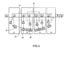
figure 3 , TFM mechanism is used in the case of a multiple levels of tunnels/encapsulations. This case outlines the utility of TL-TLV. - In fact, TL-TLV is used to indicate the level associated to a TFM. The tunnel level can be manually configured by the operator, but can also be automatically managed (e.g. automatically increased at the tunnel ingress end node and decreased at the tunnel egress end node).
- As an example, the level-1-tunnel can be a GRE tunnel and the level-2-tunnel can be an IPSec tunnel (central segment (node 32 - node 33) is supposed to be un-secured). In this case, level-1 signature of the encapsulated PTP event message (i.e. in node 1) may be the message sequence number and level-2 signature (in node 32) may be a hash function of the encrypted
PTP event message 36. - With reference to
figure 3 , theTFM 38 - is generated by the tunnel head-
end node 31 of tunnel 35 (level-1) which includes therein a firstevent message signature 37 obtained from the encapsulatedPTP event message 36; - is then modified to contain a second
event message signature 40 generated by the tunnel head-end node 32 (being also a tunnel intermediate node within the tunnel 35) of the tunnel 45 (level-2) on the basis of the encrypted (i.e. IPSec ciphering)PTP event message 36; - exits the level-2
tunnel 45 while getting rid of the level-2event message signature 40 and retaining level-1event message signature 37 relative to the level-1tunnel 35; - traverse, from the output port of the tunnel tail-end node of the
tunnel 45, the remaining nodes of thetunnel 35 with only theevent message signature 37. - As illustrated in
figure 3 , the level-2event message signature 40 is concatenated to the level-1event message signature 37. Alternatively, the formerevent message signature 40 may replace the laterevent message signature 37 in order to reduce the TFM size. - The skilled person should understand that those teachings may be extended to more than two nested tunnels wherein a PTP even message may undergo successive encapsulations/de-encapsulations.
- TCs embedded within the tunnel nodes described above, are provided with required means for TFM generation and handling. Such means may include
- means for generating a TFM;
- means for generating an event message signature using for example a hash function.
- It is to be noted that herein described method and system are independent of TC type, whatever an end-to-end or a peer-to-peer one.
- At this time, it is noteworthy to mention that the herein described embodiments are not limited to PTPv2. The skilled person should understand those teachings may concern any other synchronization protocol, or any further version of PTP making use TCs. Hence, the expression "PTP event message", cited above, may be substituted by "synchronization event message", "timing message", or more generally "synchronization message".
Claims (15)
- A method for handling at least one encapsulated synchronization message (6) by a tunnel node (1-4) including a transparent clock, said method comprising the following steps:- generating a signature (7) from the encapsulated synchronization message (6);- generating, or updating if it has already been generated, a tunnel follow-up message (8) which includes the encapsulated synchronization message signature (7);- measuring the encapsulated synchronization message residence time across the tunnel node (1-4);- updating the correction field of the tunnel follow-up message with the aforementioned measured residence time.
- The method of claim 1, wherein the signature (7) is generated using a hash function of the entire encapsulated synchronization message (6).
- The method of claim 1, wherein the signature (7) is generated using a bijective function of at least a distinctive feature of the synchronization message (6).
- The method of claim 3, wherein the distinctive feature of the synchronization message (6) is the synchronization sequence number thereof.
- The method of any of claims 1 to 4, wherein the tunnel follow-up message (8) is comprised within a maintenance message.
- The method of claim 5, wherein the tunnel follow-up message is comprised within a modified OAM LSP traceroute message.
- The method of any of claims 1 to 6, wherein the generated follow-up message (8) includes further an event message type TLV.
- The method of any of claims 1 to 7, wherein the generated follow-up message (8) includes further a tunnel level TLV.
- The method of any of claims 1 to 8, wherein the generated follow-up message (8) includes further a tunnel routing information TLV.
- The method of any of claim 1 to 9, wherein the encapsulated synchronization message is encrypted.
- The method of any of claims 1 to 10, wherein the tunnel node buffers, for a predefined duration, the tunnel follow-up message (8) while waiting for the reception of the encapsulated synchronization message (6) associated thereto.
- The method of any of claims 1 to 11, further comprising, if the tunnel node (1-4) is a tunnel tail-end node (4), a conversion step of the tunnel follow-up message (8) into a standard Follow-up message (10) containing the updated correction filed of the tunnel follow-up message (8).
- The method of any of claims 1 to 12, wherein the synchronization message is a Precision Time Protocol event message.
- A tunnel node (1-4) including a transparent clock and comprising means for generating a signature (7) from an incoming encapsulated synchronization message (6).
- The tunnel node (1-4) of claim 14, wherein the means for generating a signature (6) comprise a hash function.
Priority Applications (6)
| Application Number | Priority Date | Filing Date | Title |
|---|---|---|---|
| EP10290634A EP2461501A1 (en) | 2010-12-01 | 2010-12-01 | Tunnel follow-up message for transparent clock |
| JP2013541268A JP5717868B2 (en) | 2010-12-01 | 2011-10-25 | Transparent clock tunnel follow-up message |
| PCT/EP2011/068654 WO2012072343A1 (en) | 2010-12-01 | 2011-10-25 | Tunnel follow-up message for transparent clock |
| CN2011800644395A CN103283164A (en) | 2010-12-01 | 2011-10-25 | Tunnel follow-p message for transparent clock |
| US13/990,300 US9608750B2 (en) | 2010-12-01 | 2011-10-25 | Tunnel follow-up message for transparent clock |
| KR1020137017078A KR101504854B1 (en) | 2010-12-01 | 2011-10-25 | Tunnel follow-up message for transparent clock |
Applications Claiming Priority (1)
| Application Number | Priority Date | Filing Date | Title |
|---|---|---|---|
| EP10290634A EP2461501A1 (en) | 2010-12-01 | 2010-12-01 | Tunnel follow-up message for transparent clock |
Publications (1)
| Publication Number | Publication Date |
|---|---|
| EP2461501A1 true EP2461501A1 (en) | 2012-06-06 |
Family
ID=43828222
Family Applications (1)
| Application Number | Title | Priority Date | Filing Date |
|---|---|---|---|
| EP10290634A Withdrawn EP2461501A1 (en) | 2010-12-01 | 2010-12-01 | Tunnel follow-up message for transparent clock |
Country Status (6)
| Country | Link |
|---|---|
| US (1) | US9608750B2 (en) |
| EP (1) | EP2461501A1 (en) |
| JP (1) | JP5717868B2 (en) |
| KR (1) | KR101504854B1 (en) |
| CN (1) | CN103283164A (en) |
| WO (1) | WO2012072343A1 (en) |
Cited By (3)
| Publication number | Priority date | Publication date | Assignee | Title |
|---|---|---|---|---|
| EP2816749A1 (en) * | 2013-01-30 | 2014-12-24 | Huawei Technologies Co., Ltd. | Clock synchronization method and device |
| WO2016071138A1 (en) * | 2014-11-05 | 2016-05-12 | Telefonaktiebolaget L M Ericsson (Publ) | Transmitting residence time information in a network |
| US9369224B2 (en) | 2013-01-30 | 2016-06-14 | Huawei Technologies Co., Ltd. | Clock synchronization method and device |
Families Citing this family (10)
| Publication number | Priority date | Publication date | Assignee | Title |
|---|---|---|---|---|
| EP2712099B1 (en) * | 2012-09-19 | 2015-04-01 | Alcatel Lucent | Method for managing and maintaining an accurate distribution of time in a network when a failure occurs |
| EP2712100A1 (en) * | 2012-09-19 | 2014-03-26 | Alcatel Lucent | Method for switching from a one-way into a two-way signalling mode as a protection scheme for the distribution of time and frequency over a packet switched network |
| JP6518593B2 (en) * | 2013-01-07 | 2019-05-22 | マイクロセミ フリクエンシー アンド タイム コーポレーション | General asymmetry correction for packet timing protocols |
| US9306693B2 (en) * | 2013-11-15 | 2016-04-05 | Broadcom Corporation | Time synchronization architecture in a network device |
| US10447608B2 (en) * | 2014-11-14 | 2019-10-15 | Marvell Semiconductor, Inc. | Packet scheduling using hierarchical scheduling process with priority propagation |
| US10999250B1 (en) | 2016-08-17 | 2021-05-04 | Infersight Llc | System and method for validating a message conveyed via a network |
| US20180054417A1 (en) * | 2016-08-17 | 2018-02-22 | lnfersight LLC | Packet tracking |
| US11153213B2 (en) * | 2019-04-25 | 2021-10-19 | Hewlett Packard Enterprise Development Lp | ECMP set based on route time delay |
| US11177897B2 (en) * | 2020-02-21 | 2021-11-16 | Ciena Corporation | Distributed precision time protocol transparent clock |
| US11563709B2 (en) | 2020-03-31 | 2023-01-24 | Snap Inc. | Messaging system of partial and out-of-order events |
Family Cites Families (20)
| Publication number | Priority date | Publication date | Assignee | Title |
|---|---|---|---|---|
| JPH0715421A (en) * | 1993-06-25 | 1995-01-17 | Fuji Facom Corp | Clock synchronizing device in communication network |
| US7092361B2 (en) * | 2001-12-17 | 2006-08-15 | Alcatel Canada Inc. | System and method for transmission of operations, administration and maintenance packets between ATM and switching networks upon failures |
| US7164652B2 (en) * | 2001-12-17 | 2007-01-16 | Alcatel Canada Inc. | System and method for detecting failures and re-routing connections in a communication network |
| WO2005006670A1 (en) * | 2003-07-09 | 2005-01-20 | Fujitsu Limited | Session establishment method in label switch network and label switch node |
| US7436782B2 (en) * | 2004-03-25 | 2008-10-14 | Alcatel Lucent | Full mesh LSP and full mesh T-LDP provisioning between provider edge routers in support of Layer-2 and Layer-3 virtual private network services |
| US8111627B2 (en) * | 2007-06-29 | 2012-02-07 | Cisco Technology, Inc. | Discovering configured tunnels between nodes on a path in a data communications network |
| JP2009065579A (en) * | 2007-09-10 | 2009-03-26 | Nec Corp | Time synchronizing system, time synchronizing method, node, and program |
| US7966420B2 (en) * | 2007-10-30 | 2011-06-21 | Telefonaktiebolaget L M Ericsson (Publ) | Enhance fault tracing in multi-tiered Ethernet/MPLS network |
| CN101425890A (en) | 2008-11-21 | 2009-05-06 | 中兴通讯股份有限公司 | Transmitted clock implementing apparatus and method |
| JP2010190635A (en) * | 2009-02-17 | 2010-09-02 | Sony Corp | Slave device, method of synchronizing time of the same, master device, and electronic device system |
| CN101494613B (en) * | 2009-02-24 | 2012-04-04 | 华为技术有限公司 | Method for clock message tunnel transmission, network node and communication system |
| JP4766128B2 (en) * | 2009-02-27 | 2011-09-07 | ソニー株式会社 | Slave device, slave device time synchronization method, and electronic device system |
| JP5369814B2 (en) * | 2009-03-26 | 2013-12-18 | ソニー株式会社 | Receiving device and time correction method for receiving device |
| US8630315B2 (en) * | 2010-02-17 | 2014-01-14 | Ciena Corporation | Ethernet network synchronization systems and methods |
| JP5509914B2 (en) * | 2010-02-23 | 2014-06-04 | 富士通株式会社 | Information communication system and time synchronization method |
| US8644352B1 (en) * | 2010-03-12 | 2014-02-04 | Marvell International Ltd. | System and method for accurate time sampling in presence of output delay |
| US8976680B2 (en) * | 2010-03-15 | 2015-03-10 | Juniper Networks, Inc. | Operations, administration, and management fields for packet transport |
| CN101827098A (en) | 2010-03-31 | 2010-09-08 | 中兴通讯股份有限公司 | Processing method and device for time synchronization |
| EP2424136B1 (en) * | 2010-08-24 | 2013-10-02 | Siemens Aktiengesellschaft | System and method for time synchronization in a communication network |
| US8804736B1 (en) * | 2011-09-23 | 2014-08-12 | Juniper Networks, Inc. | Network tunneling using a label stack delimiter |
-
2010
- 2010-12-01 EP EP10290634A patent/EP2461501A1/en not_active Withdrawn
-
2011
- 2011-10-25 WO PCT/EP2011/068654 patent/WO2012072343A1/en active Application Filing
- 2011-10-25 JP JP2013541268A patent/JP5717868B2/en not_active Expired - Fee Related
- 2011-10-25 US US13/990,300 patent/US9608750B2/en active Active
- 2011-10-25 CN CN2011800644395A patent/CN103283164A/en active Pending
- 2011-10-25 KR KR1020137017078A patent/KR101504854B1/en not_active IP Right Cessation
Non-Patent Citations (5)
| Title |
|---|
| "Issues with the Transparent Clock concept of PTPv2", ITU-T SG15/Q13 INTERIM MEETING, 16 March 2009 (2009-03-16) |
| ALBERT TREYTL ET AL: "Securing IEEE 1588 by IPsec tunnels - An analysis", PRECISION CLOCK SYNCHRONIZATION FOR MEASUREMENT CONTROL AND COMMUNICATION (ISPCS), 2010 INTERNATIONAL IEEE SYMPOSIUM ON, IEEE, PISCATAWAY, NJ, USA, 27 September 2010 (2010-09-27), pages 83 - 90, XP031780849, ISBN: 978-1-4244-5978-0 * |
| DAVARI A OREN BROADCOM L MARTINI CISCO S: "Transporting PTP messages (1588) over MPLS Networks; draft-davari-tictoc-1588overmpls-00.txt", TRANSPORTING PTP MESSAGES (1588) OVER MPLS NETWORKS; DRAFT-DAVARI-TICTOC-1588OVERMPLS-00.TXT, INTERNET ENGINEERING TASK FORCE, IETF; STANDARDWORKINGDRAFT, INTERNET SOCIETY (ISOC) 4, RUE DES FALAISES CH- 1205 GENEVA, SWITZERLAND, 23 September 2010 (2010-09-23), pages 1 - 13, XP015071277 * |
| SÃ CR BASTIEN JOBERT FRANCE TELECOM FRANCE: "Issues with the Transparent Clock concept of PTPv2 in a telecom environment;28", ITU-T DRAFTS ; STUDY PERIOD 2009-2012, INTERNATIONAL TELECOMMUNICATION UNION, GENEVA ; CH, vol. Study Group 15 ; 13, 6 October 2010 (2010-10-06), pages 1 - 5, XP017448523 * |
| XU HUAWEI TECHNOLOGIES Y: "IPsec security for packet based synchronization; draft-xu-tictoc-ipsec-security-for-synchronization-00.txt", IPSEC SECURITY FOR PACKET BASED SYNCHRONIZATION; DRAFT-XU-TICTOC-IPSEC-SECURITY-FOR-SYNCHRONIZATION-00.TXT, INTERNET ENGINEERING TASK FORCE, IETF; STANDARDWORKINGDRAFT, INTERNET SOCIETY (ISOC) 4, RUE DES FALAISES CH- 1205 GENEVA, SWITZERLAND, 16 October 2010 (2010-10-16), pages 1 - 13, XP015071736 * |
Cited By (8)
| Publication number | Priority date | Publication date | Assignee | Title |
|---|---|---|---|---|
| EP2816749A1 (en) * | 2013-01-30 | 2014-12-24 | Huawei Technologies Co., Ltd. | Clock synchronization method and device |
| EP2816749A4 (en) * | 2013-01-30 | 2014-12-24 | Huawei Tech Co Ltd | Clock synchronization method and device |
| US9369224B2 (en) | 2013-01-30 | 2016-06-14 | Huawei Technologies Co., Ltd. | Clock synchronization method and device |
| WO2016071138A1 (en) * | 2014-11-05 | 2016-05-12 | Telefonaktiebolaget L M Ericsson (Publ) | Transmitting residence time information in a network |
| WO2016070947A1 (en) * | 2014-11-05 | 2016-05-12 | Telefonaktiebolaget L M Ericsson (Publ) | Transmitting residence time information in a network |
| US10567101B2 (en) | 2014-11-05 | 2020-02-18 | Telefonaktiebolaget Lm Ericsson (Publ) | Transmitting residence time information in a network |
| EP3761533A1 (en) * | 2014-11-05 | 2021-01-06 | Telefonaktiebolaget LM Ericsson (publ) | Transmitting residence time information in a network |
| US11444713B2 (en) | 2014-11-05 | 2022-09-13 | Telefonaktiebolaget Lm Ericsson (Publ) | Transmitting residence time information in a network |
Also Published As
| Publication number | Publication date |
|---|---|
| US20140036936A1 (en) | 2014-02-06 |
| KR101504854B1 (en) | 2015-03-20 |
| WO2012072343A1 (en) | 2012-06-07 |
| JP5717868B2 (en) | 2015-05-13 |
| JP2014500672A (en) | 2014-01-09 |
| CN103283164A (en) | 2013-09-04 |
| US9608750B2 (en) | 2017-03-28 |
| KR20130090920A (en) | 2013-08-14 |
Similar Documents
| Publication | Publication Date | Title |
|---|---|---|
| US9608750B2 (en) | Tunnel follow-up message for transparent clock | |
| CN107113236B (en) | Transmitting residence time information in a network | |
| US11374848B2 (en) | Explicit routing with network function encoding | |
| US9882666B2 (en) | Time synchronization for network testing equipment | |
| EP2395696B1 (en) | Clock message tunnel transmission method, network node and communication system thereof | |
| US9906457B2 (en) | Operations, administration and management fields for packet transport | |
| US9031095B2 (en) | Precision timing using a modified synchronization operation | |
| US20080304476A1 (en) | Ethernet over mpls circuit emulation service | |
| KR101488233B1 (en) | Non-intrusive method for synchronizing master and slave clocks of a packet-switched network, and associated synchronization devices | |
| US11888727B2 (en) | Extending BGP protection for SR path ingress protection | |
| CN115580569A (en) | Source routing tunnel ingress node protection | |
| KR101337054B1 (en) | Synchronizing packet sequence numbers for line card redundancy | |
| EP2458757B1 (en) | A method for transmitting IEEE 1588V2 synchronization packets over ethernet in link-by-link mode, via network elements having a transparent clock, and associated help device | |
| CN102377663A (en) | Method, device and system for processing clock message | |
| JP7039125B2 (en) | Time synchronization method, time synchronization program, time synchronization device, and time synchronization system | |
| Bui et al. | Protocol agnostic On-Path Supports |
Legal Events
| Date | Code | Title | Description |
|---|---|---|---|
| PUAI | Public reference made under article 153(3) epc to a published international application that has entered the european phase |
Free format text: ORIGINAL CODE: 0009012 |
|
| AK | Designated contracting states |
Kind code of ref document: A1 Designated state(s): AL AT BE BG CH CY CZ DE DK EE ES FI FR GB GR HR HU IE IS IT LI LT LU LV MC MK MT NL NO PL PT RO RS SE SI SK SM TR |
|
| AX | Request for extension of the european patent |
Extension state: BA ME |
|
| 17P | Request for examination filed |
Effective date: 20121206 |
|
| 111Z | Information provided on other rights and legal means of execution |
Free format text: AL AT BE BG CH CY CZ DE DK EE ES FI FR GB GR HR HU IE IS IT LI LT LU LV MC MK MT NL NO PL PT RO RS SE SI SK SM TR Effective date: 20130410 |
|
| RAP1 | Party data changed (applicant data changed or rights of an application transferred) |
Owner name: ALCATEL LUCENT |
|
| D11X | Information provided on other rights and legal means of execution (deleted) | ||
| 17Q | First examination report despatched |
Effective date: 20150706 |
|
| RAP1 | Party data changed (applicant data changed or rights of an application transferred) |
Owner name: ALCATEL LUCENT |
|
| STAA | Information on the status of an ep patent application or granted ep patent |
Free format text: STATUS: THE APPLICATION IS DEEMED TO BE WITHDRAWN |
|
| 18D | Application deemed to be withdrawn |
Effective date: 20180316 |