EP2461368A1 - Terminal board circuit - Google Patents
Terminal board circuit Download PDFInfo
- Publication number
- EP2461368A1 EP2461368A1 EP09847758A EP09847758A EP2461368A1 EP 2461368 A1 EP2461368 A1 EP 2461368A1 EP 09847758 A EP09847758 A EP 09847758A EP 09847758 A EP09847758 A EP 09847758A EP 2461368 A1 EP2461368 A1 EP 2461368A1
- Authority
- EP
- European Patent Office
- Prior art keywords
- terminal plate
- rectangular wire
- opening
- present
- projection
- Prior art date
- Legal status (The legal status is an assumption and is not a legal conclusion. Google has not performed a legal analysis and makes no representation as to the accuracy of the status listed.)
- Withdrawn
Links
Images




Classifications
-
- H—ELECTRICITY
- H02—GENERATION; CONVERSION OR DISTRIBUTION OF ELECTRIC POWER
- H02S—GENERATION OF ELECTRIC POWER BY CONVERSION OF INFRARED RADIATION, VISIBLE LIGHT OR ULTRAVIOLET LIGHT, e.g. USING PHOTOVOLTAIC [PV] MODULES
- H02S40/00—Components or accessories in combination with PV modules, not provided for in groups H02S10/00 - H02S30/00
- H02S40/30—Electrical components
- H02S40/34—Electrical components comprising specially adapted electrical connection means to be structurally associated with the PV module, e.g. junction boxes
-
- H—ELECTRICITY
- H01—ELECTRIC ELEMENTS
- H01R—ELECTRICALLY-CONDUCTIVE CONNECTIONS; STRUCTURAL ASSOCIATIONS OF A PLURALITY OF MUTUALLY-INSULATED ELECTRICAL CONNECTING ELEMENTS; COUPLING DEVICES; CURRENT COLLECTORS
- H01R11/00—Individual connecting elements providing two or more spaced connecting locations for conductive members which are, or may be, thereby interconnected, e.g. end pieces for wires or cables supported by the wire or cable and having means for facilitating electrical connection to some other wire, terminal, or conductive member, blocks of binding posts
- H01R11/01—Individual connecting elements providing two or more spaced connecting locations for conductive members which are, or may be, thereby interconnected, e.g. end pieces for wires or cables supported by the wire or cable and having means for facilitating electrical connection to some other wire, terminal, or conductive member, blocks of binding posts characterised by the form or arrangement of the conductive interconnection between the connecting locations
-
- H—ELECTRICITY
- H01—ELECTRIC ELEMENTS
- H01R—ELECTRICALLY-CONDUCTIVE CONNECTIONS; STRUCTURAL ASSOCIATIONS OF A PLURALITY OF MUTUALLY-INSULATED ELECTRICAL CONNECTING ELEMENTS; COUPLING DEVICES; CURRENT COLLECTORS
- H01R4/00—Electrically-conductive connections between two or more conductive members in direct contact, i.e. touching one another; Means for effecting or maintaining such contact; Electrically-conductive connections having two or more spaced connecting locations for conductors and using contact members penetrating insulation
- H01R4/10—Electrically-conductive connections between two or more conductive members in direct contact, i.e. touching one another; Means for effecting or maintaining such contact; Electrically-conductive connections having two or more spaced connecting locations for conductors and using contact members penetrating insulation effected solely by twisting, wrapping, bending, crimping, or other permanent deformation
- H01R4/18—Electrically-conductive connections between two or more conductive members in direct contact, i.e. touching one another; Means for effecting or maintaining such contact; Electrically-conductive connections having two or more spaced connecting locations for conductors and using contact members penetrating insulation effected solely by twisting, wrapping, bending, crimping, or other permanent deformation by crimping
- H01R4/182—Electrically-conductive connections between two or more conductive members in direct contact, i.e. touching one another; Means for effecting or maintaining such contact; Electrically-conductive connections having two or more spaced connecting locations for conductors and using contact members penetrating insulation effected solely by twisting, wrapping, bending, crimping, or other permanent deformation by crimping for flat conductive elements, e.g. flat cables
-
- H—ELECTRICITY
- H01—ELECTRIC ELEMENTS
- H01R—ELECTRICALLY-CONDUCTIVE CONNECTIONS; STRUCTURAL ASSOCIATIONS OF A PLURALITY OF MUTUALLY-INSULATED ELECTRICAL CONNECTING ELEMENTS; COUPLING DEVICES; CURRENT COLLECTORS
- H01R4/00—Electrically-conductive connections between two or more conductive members in direct contact, i.e. touching one another; Means for effecting or maintaining such contact; Electrically-conductive connections having two or more spaced connecting locations for conductors and using contact members penetrating insulation
- H01R4/10—Electrically-conductive connections between two or more conductive members in direct contact, i.e. touching one another; Means for effecting or maintaining such contact; Electrically-conductive connections having two or more spaced connecting locations for conductors and using contact members penetrating insulation effected solely by twisting, wrapping, bending, crimping, or other permanent deformation
- H01R4/18—Electrically-conductive connections between two or more conductive members in direct contact, i.e. touching one another; Means for effecting or maintaining such contact; Electrically-conductive connections having two or more spaced connecting locations for conductors and using contact members penetrating insulation effected solely by twisting, wrapping, bending, crimping, or other permanent deformation by crimping
- H01R4/183—Electrically-conductive connections between two or more conductive members in direct contact, i.e. touching one another; Means for effecting or maintaining such contact; Electrically-conductive connections having two or more spaced connecting locations for conductors and using contact members penetrating insulation effected solely by twisting, wrapping, bending, crimping, or other permanent deformation by crimping for cylindrical elongated bodies, e.g. cables having circular cross-section
- H01R4/184—Electrically-conductive connections between two or more conductive members in direct contact, i.e. touching one another; Means for effecting or maintaining such contact; Electrically-conductive connections having two or more spaced connecting locations for conductors and using contact members penetrating insulation effected solely by twisting, wrapping, bending, crimping, or other permanent deformation by crimping for cylindrical elongated bodies, e.g. cables having circular cross-section comprising a U-shaped wire-receiving portion
-
- H—ELECTRICITY
- H01—ELECTRIC ELEMENTS
- H01R—ELECTRICALLY-CONDUCTIVE CONNECTIONS; STRUCTURAL ASSOCIATIONS OF A PLURALITY OF MUTUALLY-INSULATED ELECTRICAL CONNECTING ELEMENTS; COUPLING DEVICES; CURRENT COLLECTORS
- H01R43/00—Apparatus or processes specially adapted for manufacturing, assembling, maintaining, or repairing of line connectors or current collectors or for joining electric conductors
- H01R43/16—Apparatus or processes specially adapted for manufacturing, assembling, maintaining, or repairing of line connectors or current collectors or for joining electric conductors for manufacturing contact members, e.g. by punching and by bending
-
- Y—GENERAL TAGGING OF NEW TECHNOLOGICAL DEVELOPMENTS; GENERAL TAGGING OF CROSS-SECTIONAL TECHNOLOGIES SPANNING OVER SEVERAL SECTIONS OF THE IPC; TECHNICAL SUBJECTS COVERED BY FORMER USPC CROSS-REFERENCE ART COLLECTIONS [XRACs] AND DIGESTS
- Y02—TECHNOLOGIES OR APPLICATIONS FOR MITIGATION OR ADAPTATION AGAINST CLIMATE CHANGE
- Y02E—REDUCTION OF GREENHOUSE GAS [GHG] EMISSIONS, RELATED TO ENERGY GENERATION, TRANSMISSION OR DISTRIBUTION
- Y02E10/00—Energy generation through renewable energy sources
- Y02E10/50—Photovoltaic [PV] energy
Definitions
- the present invention relates to a terminal plate circuit being able to securely hold an electrical connection state between a terminal plate and a rectangular wire even in a severe environment such as within a terminal box for solar cell panel and being suitable for automation of manufacturing processes.
- the terminal plate circuit in a case where the terminal plate circuit is used within a terminal box for solar cell panel, the electrical connection state between the terminal plate and the rectangular wire must be maintained for an extremely long period of time in the severe environment, so that the reliability has not been sufficient by a connection method implemented by only soldering or welding of the aforementioned background art.
- the terminal plate circuit disclosed in Patent Document 1 can remarkably enhance the reliability of the connected part between the terminal plate and the rectangular wire.
- the pressing member is independently needed, and therefore, there was a space to further improve this terminal plate circuit for automating the manufacturing processes.
- Patent Document 1 WO 2009/081508
- the present invention has been devised under such a circumstance of the background art, and an object thereof is to provide a terminal plate circuit in which the reliability of an electrical connection state between a terminal plate and a rectangular wire is enhanced by a method suitable for automation of manufacturing processes.
- the present invention provides a terminal plate circuit including a terminal plate and a rectangular wire, characterized in that an opening through which the rectangular wire can penetrate is formed in the terminal plate by pushing out a material of a part of the terminal plate from one side to the other side in such a manner as not to be completely separated from the terminal plate; in that the rectangular wire penetrates the terminal plate from one side to the other side thereof through the opening; and in that the rectangular wire projecting onto the other side of the terminal plate is pressed against a surface and/or an edge on the other side of the terminal plate by a projection of the terminal plate which has been formed by pushing out the material of a part of the terminal plate.
- the present invention provides a terminal plate circuit including a terminal plate and a rectangular wire, characterized in that an opening through which the rectangular wire can penetrate is formed in the terminal plate; in that the rectangular wire penetrates the terminal plate from one side to the other side thereof through the opening; and in that the rectangular wire projecting onto the other side of the terminal plate is pressed against a surface and/or an edge on the other side of the terminal plate by a projection of the terminal plate which has been formed by pushing out a material of a part of the terminal plate at a position different from the opening from one side to the other side of the terminal plate in such a manner as not to be completely separated from the terminal plate.
- the part at which the rectangular wire is pressed against the terminal plate is soldered or welded, and the terminal plate circuit is used within a terminal box for solar cell panel.
- the projection is formed by pushing out the material of a part of the terminal plate from one side to the other side, and then, the rectangular wire is pressed against the terminal plate by using the projection. Therefore, it is possible to enhance the reliability of the electrical connection state between the terminal plate and the rectangular wire by the simple configuration without using any independent component. Moreover, the terminal plate circuit of the present invention is remarkably suitable for automation of the manufacturing processes since reliable electrical connection state can be formed simply by allowing the rectangular wire to penetrate through the opening of the terminal plate and by pressing the projection of the terminal plate against the rectangular wire.
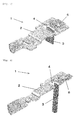
- Fig. 1 is a perspective view showing the first embodiment of a terminal plate circuit of the present invention.
- Fig. 2 is a fractured perspective view showing a contact state of constituent components in the terminal plate circuit of Fig. 1 .
- a terminal plate circuit 1 includes a terminal plate 2 and a rectangular wire 3.
- the terminal plate 2 is provided, by pushing out the material of a part of the terminal plate from lower side to upper side, with an opening 4 having such a size as to allow the rectangular wire 3 to penetrate therethrough and as to prevent the rectangular wire 3 from being largely shifted in lateral directions.
- the rectangular wire 3 is inserted into the opening 4 from the lower side of the terminal plate 2 and is penetrated to the upper side of the terminal plate 2.
- the rectangular wire 3 projecting onto the upper side of the terminal plate 2 is pressed against a surface and/or an edge on the upper side of the terminal plate by a projection 5 of the terminal plate which has been pushed out in order to form the opening 4. In this manner, the electrical connection state between the terminal plate 2 and the rectangular wire 3 becomes sure.
- the opening 4 has a size enough to allow the rectangular wire 3 to freely penetrate therethrough until the rectangular wire 3 penetrates from the lower side to the upper side.
- the opening 4 becomes narrow since the projection 5 of the terminal plate 2 which has been pushed out in order to form the opening presses the rectangular wire when the electrical connection state between the terminal plate 2 and the rectangular wire 3 is formed.
- the projection 5 of the terminal plate 2 may take any shape unless it is completely separated from the terminal plate 2: for example, it may be partly cut or may be divided into a plurality of parts.
- the important thing is that the projection 5 of the terminal plate 2, which is not completely separated from the terminal plate 2, firmly presses the rectangular wire 3 so as to establish the electrical connection state between the terminal plate 2 and the rectangular wire 3.
- the projection 5 of the terminal plate 2 may press the rectangular wire 3 against not only a single part but also a plurality of parts in the terminal plate 2: for example, it may press the rectangular wire 3 against not only the upper surface of the terminal plate 2 but also the upper edge of the opening 4.
- the rectangular wire 3 used in the terminal plate circuit 1 of the present invention may be appropriately selected from conventionally known ones.
- the terminal plate 2 should be preferably enlarged as shown in Figs. 1 and 2 in order to enhance the function for cooling a diode to be mounted thereon in the case where the terminal plate 2 is used within a terminal box for solar cell panel.
- the other constituent components used in the terminal plate circuit 1 may be appropriately selected from conventionally known ones.
- the terminal plate circuit 1 of the present invention can provide a firmer electrical connection state between the terminal plate 2 and the rectangular wire 3 by soldering or welding in such a manner as to cover the electrical contact part between the terminal plate 2 and the rectangular wire 3, in addition to pressing of the projection 5 of the terminal plate 2 against the rectangular wire 3 as described above.
- Fig. 3 is a perspective view showing the second embodiment of a terminal plate circuit of the present invention.
- Fig. 4 is a fractured perspective view showing a contact state of constituent components in the terminal plate circuit of Fig. 3 .
- the projection 5 of the terminal plate 2 is formed by pushing out the terminal plate 2 from the lower side to the upper side when forming the opening 4 through which the rectangular wire 3 penetrates.
- a major difference in the second embodiment resides in that a projection 6 of a terminal plate 2 is formed by pushing out, at a position different from an opening 4 through which a rectangular wire 3 penetrates, a material of a part of the terminal plate from the lower side to the upper side of the terminal plate in such a manner as not to be completely separated from the terminal plate, as is obvious from Figs. 3 and 4 .
- the substantial difference between the first and second embodiments is whether the projection 5 of the terminal plate 2 for pressing the rectangular wire 3 is formed from the opening 4 for allowing the rectangular wire 3 to penetrate therethrough or from the part other than the opening 4.
- the other matters are basically identical to each other between the first and second embodiments without any substantial difference.
- Fig. 5 is a perspective view showing the third embodiment of a terminal plate circuit of the present invention
- Fig. 6 is a fractured perspective view showing a contact state of constituent components in the terminal plate circuit of Fig. 5
- Fig. 7 is a perspective view showing the fourth embodiment of a terminal plate circuit of the present invention
- Fig. 8 is a fractured perspective view showing a contact state of constituent components in the terminal plate circuit of Fig. 7
- Fig. 9 is a perspective view showing the fifth embodiment of a terminal plate circuit of the present invention
- Fig. 10 is a fractured perspective view showing a contact state of constituent components in the terminal plate circuit of Fig. 9 .
- Fig. 10 is a fractured perspective view showing a contact state of constituent components in the terminal plate circuit of Fig. 9 .
- FIG. 11 is a perspective view showing the sixth embodiment of a terminal plate circuit of the present invention
- Fig. 12 is a fractured perspective view showing a contact state of constituent components in the terminal plate circuit of Fig. 11 .
- the third to sixth embodiments relate to several modifications of the projection 6 of the terminal plate 2 in the second embodiment of the present invention.
- the projection 6 of the terminal plate 2 is formed into a door, and presses the rectangular wire 3 disposed thereunder.
- a projection 6 projects in a bridge shape, and presses a rectangular wire 3 disposed thereunder.
- a projection 6 is formed into double doors by dividing a projected bridge part at the center thereof, and presses a rectangular wire 3 disposed thereunder.
- a projection 6 is formed into a door, and the opened door presses a rectangular wire 3 over an opening 4.
- a projection 6 is formed by folding an end of a terminal plate 2 from lower side to upper side, and presses a rectangular wire 3 disposed thereunder.
- the terminal plate circuit of the present invention can enhance the reliability of the electrical connection state between the terminal plate and the rectangular wire by the simple method without using any independent component, and therefore, it can be suitably adopted for automating the manufacturing processes of a terminal box for solar cell panel.
Landscapes
- Connections Effected By Soldering, Adhesion, Or Permanent Deformation (AREA)
- Photovoltaic Devices (AREA)
Abstract
Description
- The present invention relates to a terminal plate circuit being able to securely hold an electrical connection state between a terminal plate and a rectangular wire even in a severe environment such as within a terminal box for solar cell panel and being suitable for automation of manufacturing processes.
- Conventionally, in order to connect a rectangular wire electrically to a terminal plate in a terminal plate circuit, it has been carried out by providing an opening, through which the rectangular wire penetrates, in the terminal plate, inserting the rectangular wire through this opening from upper side or lower side, contacting the terminal plate with the rectangular wire electrically, and soldering or welding the contacting part.
- However, in a case where the terminal plate circuit is used within a terminal box for solar cell panel, the electrical connection state between the terminal plate and the rectangular wire must be maintained for an extremely long period of time in the severe environment, so that the reliability has not been sufficient by a connection method implemented by only soldering or welding of the aforementioned background art.
- On the other hand, as a method for enhancing the reliability of the electrical connection state between the terminal plate and the rectangular wire, fixing the rectangular wire to the terminal plate with use of a screw and thereafter soldering or welding the fixed part has been carried out conventionally; however, fixation with a screw involves formation of a screw hole and a work of mounting the screw, so that the manufacturing processes become complex and hence the above method is not desirable.
- In view of this, the applicant has already proposed a terminal plate circuit, in which a pressing member capable of sandwiching an end of a terminal plate presses a rectangular wire against the terminal plate, so as to enhance the reliability of an electrical connection state between the terminal plate and the rectangular wire (cf. Patent Document 1).
- The terminal plate circuit disclosed in
Patent Document 1 can remarkably enhance the reliability of the connected part between the terminal plate and the rectangular wire. However, the pressing member is independently needed, and therefore, there was a space to further improve this terminal plate circuit for automating the manufacturing processes. - Patent Document 1:
WO 2009/081508 - The present invention has been devised under such a circumstance of the background art, and an object thereof is to provide a terminal plate circuit in which the reliability of an electrical connection state between a terminal plate and a rectangular wire is enhanced by a method suitable for automation of manufacturing processes.
- As a result of an earnest study by the inventors of the present application in order to achieve the above object, they have found that by pressing a rectangular wire penetrating the terminal plate against the terminal plate by means of a projection formed by pushing out a material of a part of a terminal plate from one side to the other side, the reliability of an electrical connection state between the terminal plate and the rectangular wire can be readily enhanced in a method suitable for automating manufacturing processes, and thus, they have reached the completion of the present invention.
- Specifically, the present invention provides a terminal plate circuit including a terminal plate and a rectangular wire, characterized in that an opening through which the rectangular wire can penetrate is formed in the terminal plate by pushing out a material of a part of the terminal plate from one side to the other side in such a manner as not to be completely separated from the terminal plate; in that the rectangular wire penetrates the terminal plate from one side to the other side thereof through the opening; and in that the rectangular wire projecting onto the other side of the terminal plate is pressed against a surface and/or an edge on the other side of the terminal plate by a projection of the terminal plate which has been formed by pushing out the material of a part of the terminal plate.
- Moreover, the present invention provides a terminal plate circuit including a terminal plate and a rectangular wire, characterized in that an opening through which the rectangular wire can penetrate is formed in the terminal plate; in that the rectangular wire penetrates the terminal plate from one side to the other side thereof through the opening; and in that the rectangular wire projecting onto the other side of the terminal plate is pressed against a surface and/or an edge on the other side of the terminal plate by a projection of the terminal plate which has been formed by pushing out a material of a part of the terminal plate at a position different from the opening from one side to the other side of the terminal plate in such a manner as not to be completely separated from the terminal plate.
- In preferred embodiments of the terminal plate circuit of the present invention, the part at which the rectangular wire is pressed against the terminal plate is soldered or welded, and the terminal plate circuit is used within a terminal box for solar cell panel.
- In the terminal plate circuit of the present invention, the projection is formed by pushing out the material of a part of the terminal plate from one side to the other side, and then, the rectangular wire is pressed against the terminal plate by using the projection. Therefore, it is possible to enhance the reliability of the electrical connection state between the terminal plate and the rectangular wire by the simple configuration without using any independent component. Moreover, the terminal plate circuit of the present invention is remarkably suitable for automation of the manufacturing processes since reliable electrical connection state can be formed simply by allowing the rectangular wire to penetrate through the opening of the terminal plate and by pressing the projection of the terminal plate against the rectangular wire.
-
- [
Fig. 1] Fig. 1 is a perspective view of the first embodiment of a terminal plate circuit of the present invention. - [
Fig. 2] Fig. 2 is a fractured perspective view illustrating a contact state of constituent components of the first embodiment of the terminal plate circuit of the present invention. - [
Fig. 3] Fig. 3 is a perspective view of the second embodiment of a terminal plate circuit of the present invention. - [
Fig. 4] Fig. 4 is a fractured perspective view illustrating a contact state of constituent components of the second embodiment of the terminal plate circuit of the present invention. - [
Fig. 5] Fig. 5 is a perspective view of the third embodiment of a terminal plate circuit of the present invention. - [
Fig. 6] Fig. 6 is a fractured perspective view illustrating a contact state of constituent components of the third embodiment of the terminal plate circuit of the present invention. - [
Fig. 7] Fig. 7 is a perspective view of the fourth embodiment of a terminal plate circuit of the present invention. - [
Fig. 8] Fig. 8 is a fractured perspective view illustrating a contact state of constituent components of the fourth embodiment of the terminal plate circuit of the present invention. - [
Fig. 9] Fig. 9 is a perspective view of the fifth embodiment of a terminal plate circuit of the present invention. - [
Fig. 10] Fig. 10 is a fractured perspective view illustrating a contact state of constituent components of the fifth embodiment of the terminal plate circuit of the present invention. - [
Fig. 11] Fig. 11 is a perspective view of the sixth embodiment of a terminal plate circuit of the present invention. - [
Fig. 12] Fig. 12 is a fractured perspective view illustrating a contact state of constituent components of the sixth embodiment of the terminal plate circuit of the present invention. - The embodiments of the terminal plate circuit of the present invention will now be illustrated with reference to the drawings hereinafter, but the present invention is not limited thereto.
-
Fig. 1 is a perspective view showing the first embodiment of a terminal plate circuit of the present invention.Fig. 2 is a fractured perspective view showing a contact state of constituent components in the terminal plate circuit ofFig. 1 . As is obvious fromFigs. 1 and 2 , aterminal plate circuit 1 includes aterminal plate 2 and arectangular wire 3. Theterminal plate 2 is provided, by pushing out the material of a part of the terminal plate from lower side to upper side, with anopening 4 having such a size as to allow therectangular wire 3 to penetrate therethrough and as to prevent therectangular wire 3 from being largely shifted in lateral directions. Therectangular wire 3 is inserted into theopening 4 from the lower side of theterminal plate 2 and is penetrated to the upper side of theterminal plate 2. Therectangular wire 3 projecting onto the upper side of theterminal plate 2 is pressed against a surface and/or an edge on the upper side of the terminal plate by aprojection 5 of the terminal plate which has been pushed out in order to form theopening 4. In this manner, the electrical connection state between theterminal plate 2 and therectangular wire 3 becomes sure. - The
opening 4 has a size enough to allow therectangular wire 3 to freely penetrate therethrough until therectangular wire 3 penetrates from the lower side to the upper side. Theopening 4 becomes narrow since theprojection 5 of theterminal plate 2 which has been pushed out in order to form the opening presses the rectangular wire when the electrical connection state between theterminal plate 2 and therectangular wire 3 is formed. Theprojection 5 of theterminal plate 2 may take any shape unless it is completely separated from the terminal plate 2: for example, it may be partly cut or may be divided into a plurality of parts. Here, the important thing is that theprojection 5 of theterminal plate 2, which is not completely separated from theterminal plate 2, firmly presses therectangular wire 3 so as to establish the electrical connection state between theterminal plate 2 and therectangular wire 3. Theprojection 5 of theterminal plate 2 may press therectangular wire 3 against not only a single part but also a plurality of parts in the terminal plate 2: for example, it may press therectangular wire 3 against not only the upper surface of theterminal plate 2 but also the upper edge of theopening 4. - The
rectangular wire 3 used in theterminal plate circuit 1 of the present invention may be appropriately selected from conventionally known ones. Theterminal plate 2 should be preferably enlarged as shown inFigs. 1 and 2 in order to enhance the function for cooling a diode to be mounted thereon in the case where theterminal plate 2 is used within a terminal box for solar cell panel. The other constituent components used in theterminal plate circuit 1 may be appropriately selected from conventionally known ones. - The
terminal plate circuit 1 of the present invention can provide a firmer electrical connection state between theterminal plate 2 and therectangular wire 3 by soldering or welding in such a manner as to cover the electrical contact part between theterminal plate 2 and therectangular wire 3, in addition to pressing of theprojection 5 of theterminal plate 2 against therectangular wire 3 as described above. -
Fig. 3 is a perspective view showing the second embodiment of a terminal plate circuit of the present invention.Fig. 4 is a fractured perspective view showing a contact state of constituent components in the terminal plate circuit ofFig. 3 . In the above first embodiment, theprojection 5 of theterminal plate 2 is formed by pushing out theterminal plate 2 from the lower side to the upper side when forming theopening 4 through which therectangular wire 3 penetrates. A major difference in the second embodiment resides in that aprojection 6 of aterminal plate 2 is formed by pushing out, at a position different from anopening 4 through which arectangular wire 3 penetrates, a material of a part of the terminal plate from the lower side to the upper side of the terminal plate in such a manner as not to be completely separated from the terminal plate, as is obvious fromFigs. 3 and 4 . In other words, the substantial difference between the first and second embodiments is whether theprojection 5 of theterminal plate 2 for pressing therectangular wire 3 is formed from theopening 4 for allowing therectangular wire 3 to penetrate therethrough or from the part other than theopening 4. The other matters are basically identical to each other between the first and second embodiments without any substantial difference. -
Fig. 5 is a perspective view showing the third embodiment of a terminal plate circuit of the present invention, andFig. 6 is a fractured perspective view showing a contact state of constituent components in the terminal plate circuit ofFig. 5 .Fig. 7 is a perspective view showing the fourth embodiment of a terminal plate circuit of the present invention, andFig. 8 is a fractured perspective view showing a contact state of constituent components in the terminal plate circuit ofFig. 7 .Fig. 9 is a perspective view showing the fifth embodiment of a terminal plate circuit of the present invention, andFig. 10 is a fractured perspective view showing a contact state of constituent components in the terminal plate circuit ofFig. 9 .Fig. 11 is a perspective view showing the sixth embodiment of a terminal plate circuit of the present invention, andFig. 12 is a fractured perspective view showing a contact state of constituent components in the terminal plate circuit ofFig. 11 . The third to sixth embodiments relate to several modifications of theprojection 6 of theterminal plate 2 in the second embodiment of the present invention. - In the second embodiment of the present invention, the
projection 6 of theterminal plate 2 is formed into a door, and presses therectangular wire 3 disposed thereunder. In the third embodiment, aprojection 6 projects in a bridge shape, and presses arectangular wire 3 disposed thereunder. In the fourth embodiment, aprojection 6 is formed into double doors by dividing a projected bridge part at the center thereof, and presses arectangular wire 3 disposed thereunder. In the fifth embodiment, aprojection 6 is formed into a door, and the opened door presses arectangular wire 3 over anopening 4. In the sixth embodiment, aprojection 6 is formed by folding an end of aterminal plate 2 from lower side to upper side, and presses arectangular wire 3 disposed thereunder. The other matters are basically identical to those in the first and second embodiments of the present invention. - The terminal plate circuit of the present invention can enhance the reliability of the electrical connection state between the terminal plate and the rectangular wire by the simple method without using any independent component, and therefore, it can be suitably adopted for automating the manufacturing processes of a terminal box for solar cell panel. Explanation of Reference Number
-
- 1:
- terminal plate circuit
- 2:
- terminal plate
- 3:
- rectangular wire
- 4:
- opening
- 5:
- projection
- 6:
- projection
Claims (5)
- A terminal plate circuit including a terminal plate and a rectangular wire, characterized in that an opening through which the rectangular wire can penetrate is formed in the terminal plate by pushing out a material of a part of the terminal plate from one side to the other side in such a manner as not to be completely separated from the terminal plate; in that the rectangular wire penetrates the terminal plate from one side to the other side thereof through the opening; and in that the rectangular wire projecting onto the other side of the terminal plate is pressed against a surface and/or an edge on the other side of the terminal plate by a projection of the terminal plate which has been formed by pushing out the material of a part of the terminal plate.
- The terminal plate circuit according to claim 1, wherein the part at which the rectangular wire is pressed against the terminal plate is soldered or welded.
- A terminal plate circuit including a terminal plate and a rectangular wire, characterized in that an opening through which the rectangular wire can penetrate is formed in the terminal plate; in that the rectangular wire penetrates the terminal plate from one side to the other side thereof through the opening; and in that the rectangular wire projecting onto the other side of the terminal plate is pressed against a surface and/or an edge on the other side of the terminal plate by a projection of the terminal plate which has been formed by pushing out a material of a part of the terminal plate at a position different from the opening from one side to the other side of the terminal plate in such a manner as not to be completely separated from the terminal plate.
- The terminal plate circuit according to claim 3, wherein the part at which the rectangular wire is pressed against the terminal plate is soldered or welded.
- The terminal plate circuit according to any one of claims 1 to 4, wherein the terminal plate circuit is used within a terminal box for solar cell panel.
Applications Claiming Priority (1)
| Application Number | Priority Date | Filing Date | Title |
|---|---|---|---|
| PCT/JP2009/003528 WO2011013163A1 (en) | 2009-07-27 | 2009-07-27 | Terminal board circuit |
Publications (2)
| Publication Number | Publication Date |
|---|---|
| EP2461368A1 true EP2461368A1 (en) | 2012-06-06 |
| EP2461368A4 EP2461368A4 (en) | 2014-04-30 |
Family
ID=43528846
Family Applications (1)
| Application Number | Title | Priority Date | Filing Date |
|---|---|---|---|
| EP09847758.1A Withdrawn EP2461368A4 (en) | 2009-07-27 | 2009-07-27 | Terminal board circuit |
Country Status (3)
| Country | Link |
|---|---|
| EP (1) | EP2461368A4 (en) |
| JP (1) | JP5406843B2 (en) |
| WO (1) | WO2011013163A1 (en) |
Families Citing this family (5)
| Publication number | Priority date | Publication date | Assignee | Title |
|---|---|---|---|---|
| EP2769418A1 (en) * | 2011-10-19 | 2014-08-27 | Saint-Gobain Glass France | Solar module with ribbon cable, and a method for the manufacture of same |
| WO2013073608A1 (en) * | 2011-11-18 | 2013-05-23 | シャープ株式会社 | Solar cell module, solar cell module production method, and solar cell module production device |
| JP2013165236A (en) * | 2012-02-13 | 2013-08-22 | Sharp Corp | Terminal box, solar cell module, connection method between output lead wire and terminal box, and manufacturing method of solar cell module |
| JP6377359B2 (en) * | 2014-02-10 | 2018-08-22 | 木谷電器株式会社 | Connection structure, terminal board, and photovoltaic power generation system |
| JP2021140859A (en) * | 2020-02-29 | 2021-09-16 | 三洋電機株式会社 | Soldering structure and battery pack of soldering structure |
Family Cites Families (8)
| Publication number | Priority date | Publication date | Assignee | Title |
|---|---|---|---|---|
| JPS5219680U (en) * | 1975-07-30 | 1977-02-12 | ||
| SE428743C (en) * | 1979-12-27 | 1987-07-09 | Bakelit Konstr Ab | ELECTRICAL CONNECTOR |
| JPS5820515U (en) * | 1981-07-30 | 1983-02-08 | 日本アビオニクス株式会社 | coil or transformer |
| JPH0713196Y2 (en) * | 1989-11-01 | 1995-03-29 | 株式会社ニチフ端子工業 | Electrical connector |
| FI89116C (en) * | 1990-09-28 | 1993-08-10 | Helvar Oy | Wiring and procedure for its manufacture |
| JPH05114423A (en) * | 1991-10-23 | 1993-05-07 | Tokyo Electric Co Ltd | Wire connection terminal |
| JP4481852B2 (en) * | 2005-03-17 | 2010-06-16 | 豊田鉄工株式会社 | Floating connector device |
| EP2149932B1 (en) | 2007-12-26 | 2014-05-14 | Onamba Co., Ltd. | Terminal plate circuit using pushing member |
-
2009
- 2009-07-27 WO PCT/JP2009/003528 patent/WO2011013163A1/en not_active Ceased
- 2009-07-27 EP EP09847758.1A patent/EP2461368A4/en not_active Withdrawn
- 2009-07-27 JP JP2010532132A patent/JP5406843B2/en not_active Expired - Fee Related
Also Published As
| Publication number | Publication date |
|---|---|
| JPWO2011013163A1 (en) | 2013-01-07 |
| WO2011013163A1 (en) | 2011-02-03 |
| EP2461368A4 (en) | 2014-04-30 |
| JP5406843B2 (en) | 2014-02-05 |
Similar Documents
| Publication | Publication Date | Title |
|---|---|---|
| EP2149932A1 (en) | Terminal plate circuit usisng pushing member | |
| US9711876B2 (en) | Clamping spring | |
| US8579651B2 (en) | Connection device for conductors | |
| US9806442B2 (en) | Plug connection device | |
| US20160164196A1 (en) | Conductive wire connection structure of rail-type electrical terminal | |
| US20090068863A1 (en) | Connecting terminal | |
| US20190131723A1 (en) | Idcc connection system and process | |
| RU2638306C2 (en) | Method of electrical component connection with electrical component carrier and device | |
| US9614299B2 (en) | Device for attaching and contacting an electrical component and method for manufacturing the device | |
| US20170040938A1 (en) | Photovoltaic Junction Box and Photovoltaic Junction Module | |
| JP6555028B2 (en) | Cable crimp terminal assembly | |
| CN108574151B (en) | Mounting aid for mounting electrical components on a printed circuit board and mounting method | |
| CN104518307A (en) | Lead wire connection structure and electronic device including the same | |
| JP5406843B2 (en) | Terminal board circuit | |
| JP2012074376A (en) | Level bridge | |
| US12620733B2 (en) | Insulating piercing contact with wire retention feature | |
| JP6275544B2 (en) | Terminal fixing structure and circuit breaker | |
| EP2503642A1 (en) | Terminal strip circuit | |
| CN103109422B (en) | Method for producing pin-shaped contact elements and contact element | |
| JP2004213956A (en) | Connector | |
| JP4922777B2 (en) | How to connect terminals to metal plates | |
| US8920198B2 (en) | Electrical connecting element and combination comprising an electrical connecting element and component | |
| JP2008306819A (en) | Conductive material | |
| JP2012243571A (en) | Connection structure of terminal fitting | |
| EP3047498B1 (en) | Active electrical component |
Legal Events
| Date | Code | Title | Description |
|---|---|---|---|
| PUAI | Public reference made under article 153(3) epc to a published international application that has entered the european phase |
Free format text: ORIGINAL CODE: 0009012 |
|
| 17P | Request for examination filed |
Effective date: 20111230 |
|
| AK | Designated contracting states |
Kind code of ref document: A1 Designated state(s): AT BE BG CH CY CZ DE DK EE ES FI FR GB GR HR HU IE IS IT LI LT LU LV MC MK MT NL NO PL PT RO SE SI SK SM TR |
|
| DAX | Request for extension of the european patent (deleted) | ||
| A4 | Supplementary search report drawn up and despatched |
Effective date: 20140328 |
|
| RIC1 | Information provided on ipc code assigned before grant |
Ipc: H01L 31/048 20140101AFI20140324BHEP Ipc: H01R 4/02 20060101ALI20140324BHEP |
|
| STAA | Information on the status of an ep patent application or granted ep patent |
Free format text: STATUS: THE APPLICATION IS DEEMED TO BE WITHDRAWN |
|
| 18D | Application deemed to be withdrawn |
Effective date: 20180201 |