EP2461308B1 - Joint - Google Patents
Joint Download PDFInfo
- Publication number
- EP2461308B1 EP2461308B1 EP20110250919 EP11250919A EP2461308B1 EP 2461308 B1 EP2461308 B1 EP 2461308B1 EP 20110250919 EP20110250919 EP 20110250919 EP 11250919 A EP11250919 A EP 11250919A EP 2461308 B1 EP2461308 B1 EP 2461308B1
- Authority
- EP
- European Patent Office
- Prior art keywords
- seal
- legs
- head
- channel
- leg
- Prior art date
- Legal status (The legal status is an assumption and is not a legal conclusion. Google has not performed a legal analysis and makes no representation as to the accuracy of the status listed.)
- Not-in-force
Links
Images


Classifications
-
- G—PHYSICS
- G09—EDUCATION; CRYPTOGRAPHY; DISPLAY; ADVERTISING; SEALS
- G09F—DISPLAYING; ADVERTISING; SIGNS; LABELS OR NAME-PLATES; SEALS
- G09F3/00—Labels, tag tickets, or similar identification or indication means; Seals; Postage or like stamps
- G09F3/02—Forms or constructions
- G09F3/03—Forms or constructions of security seals
- G09F3/0305—Forms or constructions of security seals characterised by the type of seal used
- G09F3/0311—Forms or constructions of security seals characterised by the type of seal used having arrow-like sealing means
Definitions
- the present invention relates to an improved seal for a security device, for example a security device being particularly adapted for use for example in sealing reusable mailing pouches, or other arrangements.
- Re-usable security envelopes for securely transferring mail are well known. Typically they comprise a sealable bag, a fastening means and a security device.
- the bag is made from durable material such as a plastics or canvas material and the fastening means typically comprises a fastener which is movable between an open position, which allows access to the interior of the bag, and a closed position in which the bag is sealed to prevent access to the bag's interior and any contents therein.
- the security device typically comprises a fixed locking housing and a seal means of locking the fastening means thereto. In use, articles to be securely mailed are placed in the bag and the fastener moved to the closed position. Attached to the bag adjacent to the closed position of the fastener is the fixed locking housing to which the fastener may be detachably engaged by means of a tab attached to the fastener.
- FIG. 2 of this application An early prior art seal is shown in figure 2 of this application and described in GB1424680 .
- the seal of GB1424680 can be seen to be arrow shaped, with a body portion and an arrowhead portion including two barbs.
- EP1547932 again includes a body portion and a head portion, the head being arrow shaped and comprising two barbs.
- This head also includes a longitudingal groove along the head part In addition to an indent at its tip.
- EP1701327 Two further prior art seals are described in EP1701327 , the first (shown in figures 1a-2 is described as a conventional seal of the type shown in GB1424680 and WO02/16215 . It can be seen to have a head, which is arrow shaped with two barbs, and a body. Between the head and the body is a neck portion including a line of weakness. EP1701327 also shows a rather different seal which includes two head parts each having inwardly facing barbs.
- this second seal is used in a housing which includes a T-shaped or hammer-head shaped projection which effectively splits the housing into two separate chambers, one for each head.
- GB2420743 discloses a rather different shaped arrowhead seal in which instead of resilient barbs extending from an arrow-shaped head, a pair of triangular legs are provided.
- the market favours seals with resilient barbs because they lock in position more easily.
- each leg When the seal is broken, because each leg includes a region of weakness which is selectively fracturable instead of a single neck/head portion which is broken at a line of weakness, the break results in two separate pieces (the legs) remaining in the locking housing. Because there are two separate pieces inside the housing, the legs can be removed relatively easily compared to removal of a fractured head, which can easily become stuck in the housing and sometimes requires tools (for example a piece of wire) to enable removal.
- a platform is provided between the body portion and the legs.
- the head includes a body portion having shoulders and the end of the channel, which separates the legs, extends at least in line with the shoulders. While disadvantageous in terms of robustness, this is particularly effective in ensuring that the legs break off separately and are easily removed. Even more preferably the end of the channel extends beyond the shoulder into the body portion.
- the channel is wider than the narrow portion of the legs.
- a wide channel provides room for the two legs to move towards each other and thereby easily fall out of the opening in the locking housing.
- the seal further comprises a ledge extending away from the seal in a direction perpendicular to the plane of the head. More preferably, the ledge extends across the width of both legs.
- each outer leg is adapted to resiliently deflect towards a respective inner leg when inserted into the lock opening thereby reducing the distance between respective outer and inner legs.
- said region of weakness is defined by a trough extending between an outside edge of said wider portion towards said channel.
- a trough is a simple weakening mechanism and particularly effective for breaking when the body portion is pulled upward from its seat, but not breaking due to lateral movement
- said trough is V-shaped. This allows easy removal of the seal from a tool.
- said trough is formed on an upper and a lower surface of said wider portion.
- said region of weakness is defined by at least one opening positioned in said wider portion of each inner leg.
- At least a portion of said fastener is covered by the seal.
- the seal is adapted to fracture into at least three component parts.
- the seal may fracture into the body part, and two leg parts (each leg part including inner and outer legs).
- Figure 1 shows a prior art seal 2 comprising a head portion 4 connected to a tail portion 6, via a frangible joining member 8.
- Head portion 4 is shown as a generally rectangular, planar body, but examples include curved sides or any other suitable shape.
- Tail portion 6 extends in the plane of head portion 4 and comprises shaft 10. From end 12 of shaft 10 distal head portion 4 extends a pair of fingers 14, one either side of shaft 10 in the plane of head portion 4, each finger 14 lying parallel to shaft 10 and extending back towards head 4.
- Each finger 14 is resiliently deformable, at least in the plane of the head 104, and has a length which is slightly shorter than the length of shaft 10, end 16 of each finger 14 stopping short of frangible joining member 8.
- End 12 of shaft 10 includes an optional indentation 18, and the shaft may include a central trough (not shown) on one side extending form end 12 to, or close to, frangible joining member 8. Such an indentation and/or trough may be used for positioning purposes.
- Frangible joining member 8 comprises a platform extending away from and in the plane of the head portion, narrower than the head portion and including a region 20 which has less material than is generally present in the rest of the seal. The presence of thinner portion 20 in the frangible joining member 8 provides a weak area of the seal at which the head portion may be detached from the tail portion.
- Figure 2 shows a prior art locking housing and seal, in which a prior art seal 50 is adapted to engage with the locking housing 52 through opening 54.
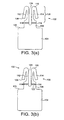
- Figure 3(a) shows a first side of a seal 102 in accordance with a first, preferred embodiment of the present invention.
- the seal includes a head 104 connected to a pair of legs 106 via a joining member 108.
- Head 104 is a generally rectangular, planar body, but it is contemplated that the body may have rounded corners, be generally circular or have some other suitable shape.
- Joining member 108 comprises a platform integral with but narrower than head 104, which extends away from and in the plane of head 104.
- legs 106 are integral with head 104 and platform 108 and extend substantially in the plane of head 104, and platform 108, from respective regions on an edge of platform 108 distal head 104.
- Each leg 106 comprises a first part 112 extending away from platform 108 and a second part 114 extending from an end 116 of first part 112 distal platform 108 back towards platform 108.
- the second part 114 of a first of the pair of legs extends away from the first part 112 of the second of the pair of legs, and vice versa.
- each leg 106 forms the shape of an elongate hook.
- First part 112 of legs 106 have a first width adjacent platform 108, an external edge of each leg aligned with an external edge of platform 108, and a second, reduced width towards end 116 of first part 112, the second portion 114 of each leg being positioned partially within the space provided by the narrowed first portion.
- Legs 106 are resiliently axially and laterally deformable about the gap 124 between the pair of legs 106.
- the first, wider portion of the first part 112 of each leg 110 includes a V-shaped indentation 118 along the width of the leg.
- This indentation provides for a line 119 along the width of the leg, at the point of the 'V', at which the material is at its thinnest. This provides a weak point at which any force exerted on the leg will be focussed and where the legs may be snapped off providing a clean break.
- the V-shaped indentation may extend along only a portion of the width of the leg, being positioned intermediate two end walls (not shown).
- the weakened section may optionally or alternatively include an opening 122, in accordance with a second embodiment of the present invention, as seen in Figure 3(b) .
- the presence of the indentation and/or opening provides a frangible portion of each leg at which the leg may be detached from platform 108.
- platform 108 in the seal, joining head 104 and legs 106 together, has the particular advantage that legs 106 can be shorter. The longer the legs 106 the more vulnerable they are to unintentional snapping during careless or rushed handling and use, and so platform 108 renders the seal more robust.
- Figure 5 shows a first side of a seal 102 in accordance with a third embodiment of the present invention.
- the seal of Figure 5 is similar to the seal of Figure 3 , a difference being in the width of platform 108, which extends beyond an outer edge of the first, wider part of each leg 106. Such an extended width may provide for an even more robust seal than the arrangement of Figure 3
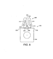
- Figure 6 shows the seal of Figure 5 from the opposite side, with optional openings 122.
- the openings as shown are circular, but may be any suitable shape.
- Figure 7(a) shows a back view of a seal in accordance with a fourth embodiment of the present invention.
- Figure 7(a) shows a short ledge 150 positioned on joining member 108 adjacent head 104 and extending away from joining member 108 in a direction perpendicular to the plane of the head 104, legs 106 and joining member 108.
- ledge 150 extends across the width of joining member 108 in particular across the width of both legs 112 and gap 124and extends away from joining member 108 to a distance approximately the same as the length of the first, wider, portion of each leg.
- Figure 7(b) shows a perspective view of the seal of Figure 7(a) , showing ledge 150 positioned on a back surface of a seal, with ledge 150 extending away from the back surface of the seal in a direction perpendicular to the plane of the seal.
- Figure 7(c) shows a side view of the seal of Figures 7(a) and (b) .
- Figure 7(d) shows a back view of a strip of the seals of Figures 7(a) - (c) .
- a seal in accordance with the present invention may be used in any one of many well-known locking housings, for example the locking housing 52 in Figure 2 .
- legs 106 return to their rest position, an arrangement in which second parts 114 extend beyond the width of entry way 60. If head 104 is then urged away from chamber 58 to withdraw seal 102 from chamber 58 through entry way 60, ends 126 of respective second parts 114 engage with respective shoulders provided within chamber 58 on either side of entry way 60, latching the seal in place.
- Tab 54 of zip 56 may only be released by breaking seal 102, for example by snapping the legs at weak point 119. With the seal removed, tab 54 may then be disengaged from chamber 58 and the zip or fastener may be opened to allow access to the contents of the bag. With legs 106 detached from head 104, legs 106 remain loose in chamber 58. Individual legs 106 are sufficiently small to easily be removed from chamber 58, for example legs 110 readily fall out from chamber 58.
- tab 54 of zip 56 may be released by breaking seal 102 by snapping the legs 106 at weak point 119. During this process ledge 150 is urged against the locking housing, asserting even more force on the weakened point 119 of legs 106, efficiently breaking the seal.
- the seal includes a head 204 connected to a pair of legs 206, in this case there is no joining member.
- Head 204 is again a generally rectangular, planar body, but it is contemplated that the body may have rounded corners, be generally circular or have some other suitable shape.
- legs 206 are integral with head 204 and extend substantially in the plane of head 204, from respective regions on a distal edge of the head 204.
- Each leg 206 comprises a first part 212 extending away from the head 204 and a second part 214 extending from an end 216 of first part 212 distal the head 204 back towards the head 204.
- the second part 214 of a first of the pair of legs extends away from the first part 212 of the second of the pair of legs, and vice versa.
- each leg 206 forms the shape of an elongate hook.
- first parts 212 of legs 206 have a first width adjacent head 204, an external edge of each leg aligned with an external edge of head 204, and a second, reduced width towards end 216 of first part 212, the second portion 214 of each leg being positioned partially within the space provided by the narrowed first portion.
- Legs 206 are resiliently axially and laterally deformable about the channel 224 between the pair of legs 206.
- the first, wider portion of the first part 212 of each leg 216 includes a V-shaped indentation 218 along the width of the leg.
- This indentation provides for a line 219 along the width of the leg, at the point of the 'V', at which the material is at its thinnest. This provides a weak point at which any force exerted on the leg will be focussed and where the legs may be snapped off providing a clean break.
- the V-shaped indentation may extend along only a portion of the width of the leg, being positioned intermediate two end walls (not shown).
- the weakened section may optionally or alternatively include an opening 222.
- the presence of the indentation and/or opening provides a frangible portion of each leg at which the leg may be detached from the head 204.
- the channel 224 of the fifth embodiment extends into the body portion forming a cutout 230 set back from the shoulders 232 of the body portion of the head. It is essential that the channel extends past the point of weakness in order that the legs break off separately; to ensure that the legs break off separately it is preferred that the channel extends at least parallel with the shoulders 232; and most preferred that as shown the channel extends into the body portion.
- weakened region 118 may be weakened by other means, for example the weakened region may comprise a channel or trough, which includes less material than that generally present in the rest of the leg 106, but without weakened line 119.
- the channel or trough may extend along the whole width of each leg or extend along only part of each leg, intermediate end walls (not shown).
- the weakened region may include a series of openings rather than the one present in Figures, or the V section or channel may not extend along the entire width of the first thicker portion of first part 112.
- the V section may be present on only one side of the seal, as shown in Figures 3 to 6 , or may be present on both sides of the seal.
- Ledge 150 may have a length that is different from the length of the first, wider portion of each leg, for example, it may be longer.
- ledge 150 may be positioned in a slightly different position on the seal, and may be wider or narrower.
- the head may further include beading on a planar surface (not shown) to thicken the head, or may alternatively or additionally include a single thicker portion, for example a central circular thicker portion shown on Figure 8 . Including such thicker portions to the seal head provides for a more robust seal and also assists in suitable positioning of the seal on entry into locking chambers.
Claims (16)
- Joint (102, 202) pour un produit scellable qui inclut un élément de fixation et un dispositif de fermeture destiné à fixer ledit élément de fixation, dans lequel ledit dispositif de fermeture comprend un boitier de verrouillage ayant une ouverture de verrouillage avec des épaulements de chaque côté de celui-ci, un couvercle de languette connecté à l'élément de fixation et pouvant être engagé avec le boitier de verrouillage, où ledit joint (102, 202) comprend :une tête (104, 204), etune paire de pattes intérieures parallèles, séparées par un canal (124, 224), chaque patte intérieure (106, 206) incluant une première partie large adjacente à ladite tête (104, 204) et se rétrécissant sur un bord extérieur distal par rapport audit canal (124, 224) pour former une deuxième partie étroite, à partir d'une extrémité de laquelle, de manière distale par rapport à ladite première partie large, s'étend, en s'écartant dudit canal (124, 224) et en direction de ladite première partie large, une patte extérieure déformable de manière résiliente en direction de ladite partie étroite de ladite patte intérieure (106, 206), et incluant à une extrémité proximale par rapport à ladite partie large de ladite patte intérieure, et s'étendant à l'extérieure d'une largeur de celle-ci, une surface (126), positionnée pour un engagement de verrouillage derrière un dit épaulement respectif, dans lequel ladite première partie large de chaque patte intérieure (106, 206) inclut une région de faiblesse (118, 218) qui peut être cassée et caractérisé en ce que chaque patte de ladite paire de pattes intérieures (106, 206) est déformable de manière résiliente dans ledit canal (124, 224)
- Joint selon la revendication 1 où ledit joint (102, 202) est de forme plane.
- Joint selon la revendication 1 ou 2 dans lequel chaque patte extérieure (114, 214) est destinée à se courber de manière résiliente en direction d'une patte intérieure respective lorsqu'elle est insérée dans l'ouverture de verrouillage en réduisant de cette manière la distance entre les pattes extérieure et intérieure respectives.
- Joint selon l'une quelconque des revendications précédentes dans lequel ladite région de faiblesse (118, 218) est définie par une cuvette formée sur une surface supérieure et/ou inférieure de ladite partie plus large s'étendant entre un bord extérieur de ladite partie plus large en direction dudit canal.
- Joint selon la revendication 4 dans lequel ladite cuvette est en forme de V.
- Joint selon l'une quelconque des revendications 1 à 3 dans lequel ladite région de faiblesse est définie par au moins une ouverture (122, 222) positionnée dans ladite partie plus large de chaque patte intérieure,
- Joint selon l'une quelconque des revendications 1 à 6 dans lequel ladite région de faiblesse (118, 218) est définie par une cuvette et au moins une ouverture.
- Joint selon l'une quelconque des revendications précédentes dans lequel, avec ledit joint (102, 202) inséré dans ledit boitier de verrouillage, au moins une partie dudit élément de fixation est couverte par le joint.
- Joint selon l'une quelconque des revendications précédentes où le joint (102, 202) est destiné à se rompre en au moins trois parties constitutives.
- Joint selon l'une quelconque des revendications précédentes dans lequel le canal (124, 224) est plus large que la partie étroite des pattes.
- Joint selon l'une quelconque des revendications précédentes dans lequel la distance dans le sens de largeur de la surface, positionnée pour un engagement de verrouillage derrière un dit épaulement respectif à l'extrémité proximale par rapport à ladite partie large de ladite patte intérieure, et s'étendant à l'extérieure d'une largeur de celle-ci, est définie par x et la largeur du canal est définie par y, et y>2x.
- Joint selon l'une quelconque des revendications précédentes dans lequel la tête (104, 204) inclut une partie de corps ayant des épaulements et l'extrémité du canal, qui sépare les pattes, s'étend au moins en alignement avec les épaulements.
- Joint selon la revendication 11 dans lequel l'extrémité du canal (124, 224) s'étend au-delà de l'épaulement jusque dans la partie de corps.
- Joint selon l'une quelconque des revendications de 1 à 12 dans lequel la tête (104, 204) inclut une plate-forme prévue entre la partie de corps et les pattes.
- Joint selon l'une quelconque des revendications précédentes comprenant en outre une corniche (150) s'étendant à distance du joint (102, 202) dans une direction perpendiculaire au plan de la tête (104, 204).
- Joint selon la revendication 14 dans lequel la corniche (150) s'étend sur la largeur des deux pattes.
Applications Claiming Priority (2)
| Application Number | Priority Date | Filing Date | Title |
|---|---|---|---|
| GBGB1020608.4A GB201020608D0 (en) | 2010-12-06 | 2010-12-06 | Seal |
| GBGB1104810.5A GB201104810D0 (en) | 2010-12-06 | 2011-03-22 | Seal |
Publications (3)
| Publication Number | Publication Date |
|---|---|
| EP2461308A2 EP2461308A2 (fr) | 2012-06-06 |
| EP2461308A3 EP2461308A3 (fr) | 2012-10-17 |
| EP2461308B1 true EP2461308B1 (fr) | 2014-05-14 |
Family
ID=43531503
Family Applications (1)
| Application Number | Title | Priority Date | Filing Date |
|---|---|---|---|
| EP20110250919 Not-in-force EP2461308B1 (fr) | 2010-12-06 | 2011-12-06 | Joint |
Country Status (2)
| Country | Link |
|---|---|
| EP (1) | EP2461308B1 (fr) |
| GB (3) | GB201020608D0 (fr) |
Families Citing this family (1)
| Publication number | Priority date | Publication date | Assignee | Title |
|---|---|---|---|---|
| CN108945792A (zh) * | 2018-08-29 | 2018-12-07 | 西安西正印制有限公司 | 一种储运箱 |
Family Cites Families (9)
| Publication number | Priority date | Publication date | Assignee | Title |
|---|---|---|---|---|
| GB1424680A (en) | 1972-12-13 | 1976-02-11 | Envopak Ltd | Locking device |
| GB2362430B (en) * | 2000-02-08 | 2002-12-04 | Transvaal Rubber Company | Slide fastener security tag |
| GB0020951D0 (en) | 2000-08-24 | 2000-10-11 | Envopak Group Ltd | Closeable container |
| GB0329665D0 (en) | 2003-12-22 | 2004-01-28 | Itw Ltd | Long-necked seal |
| GB0426408D0 (en) | 2004-12-02 | 2005-01-05 | Versapak Internat Ltd | Sealing device |
| GB0504776D0 (en) * | 2005-03-08 | 2005-04-13 | Itw Ltd | Security seal |
| CN201429930Y (zh) * | 2009-06-23 | 2010-03-24 | 北京科创融鑫科技有限公司 | 保险止退装置及包装袋 |
| CN201472791U (zh) * | 2009-09-01 | 2010-05-19 | 孙成明 | 运钞袋的防盗保险装置 |
| UA52631U (en) * | 2010-07-14 | 2010-08-25 | Дмитрий Юрьевич Казавчинский | Lead seal device |
-
2010
- 2010-12-06 GB GBGB1020608.4A patent/GB201020608D0/en not_active Ceased
-
2011
- 2011-03-22 GB GBGB1104810.5A patent/GB201104810D0/en not_active Ceased
- 2011-12-06 GB GB1120986.3A patent/GB2486338A/en not_active Withdrawn
- 2011-12-06 EP EP20110250919 patent/EP2461308B1/fr not_active Not-in-force
Also Published As
| Publication number | Publication date |
|---|---|
| GB2486338A (en) | 2012-06-13 |
| GB201104810D0 (en) | 2011-05-04 |
| GB201020608D0 (en) | 2011-01-19 |
| GB201120986D0 (en) | 2012-01-18 |
| EP2461308A2 (fr) | 2012-06-06 |
| EP2461308A3 (fr) | 2012-10-17 |
Similar Documents
| Publication | Publication Date | Title |
|---|---|---|
| CA2538396C (fr) | Fermeture de securite | |
| US20110142372A1 (en) | Sealed container | |
| US5088159A (en) | Security seal bracelet | |
| EP3139367B1 (fr) | Dispositif d'obturation | |
| US7360807B2 (en) | Seals | |
| EP2461308B1 (fr) | Joint | |
| EP1248539B1 (fr) | Recipient refermable | |
| AU2005200150B2 (en) | Closable container | |
| AU2007291921B2 (en) | Tamper evident device | |
| GB2420743A (en) | Tamper resistant sealing device | |
| WO2001058303A1 (fr) | Embout de securite pour fermeture a glissiere | |
| WO2006059154A2 (fr) | Dispositif d'etancheite | |
| NZ723741B2 (en) | Sealing device | |
| EP2441519A2 (fr) | Support de sécurité | |
| GB2550841A (en) | Tamper-evident closures for flexible bags | |
| ZA200106634B (en) | Slide fastener security tag. |
Legal Events
| Date | Code | Title | Description |
|---|---|---|---|
| PUAI | Public reference made under article 153(3) epc to a published international application that has entered the european phase |
Free format text: ORIGINAL CODE: 0009012 |
|
| AK | Designated contracting states |
Kind code of ref document: A2 Designated state(s): AL AT BE BG CH CY CZ DE DK EE ES FI FR GB GR HR HU IE IS IT LI LT LU LV MC MK MT NL NO PL PT RO RS SE SI SK SM TR |
|
| AX | Request for extension of the european patent |
Extension state: BA ME |
|
| PUAL | Search report despatched |
Free format text: ORIGINAL CODE: 0009013 |
|
| RIC1 | Information provided on ipc code assigned before grant |
Ipc: G09F 3/03 20060101AFI20120906BHEP |
|
| AK | Designated contracting states |
Kind code of ref document: A3 Designated state(s): AL AT BE BG CH CY CZ DE DK EE ES FI FR GB GR HR HU IE IS IT LI LT LU LV MC MK MT NL NO PL PT RO RS SE SI SK SM TR |
|
| AX | Request for extension of the european patent |
Extension state: BA ME |
|
| 17P | Request for examination filed |
Effective date: 20121122 |
|
| GRAP | Despatch of communication of intention to grant a patent |
Free format text: ORIGINAL CODE: EPIDOSNIGR1 |
|
| INTG | Intention to grant announced |
Effective date: 20131217 |
|
| GRAS | Grant fee paid |
Free format text: ORIGINAL CODE: EPIDOSNIGR3 |
|
| GRAA | (expected) grant |
Free format text: ORIGINAL CODE: 0009210 |
|
| AK | Designated contracting states |
Kind code of ref document: B1 Designated state(s): AL AT BE BG CH CY CZ DE DK EE ES FI FR GB GR HR HU IE IS IT LI LT LU LV MC MK MT NL NO PL PT RO RS SE SI SK SM TR |
|
| REG | Reference to a national code |
Ref country code: GB Ref legal event code: FG4D |
|
| REG | Reference to a national code |
Ref country code: AT Ref legal event code: REF Ref document number: 668800 Country of ref document: AT Kind code of ref document: T Effective date: 20140615 |
|
| REG | Reference to a national code |
Ref country code: IE Ref legal event code: FG4D Ref country code: DE Ref legal event code: R096 Ref document number: 602011006898 Country of ref document: DE Effective date: 20140618 |
|
| REG | Reference to a national code |
Ref country code: AT Ref legal event code: MK05 Ref document number: 668800 Country of ref document: AT Kind code of ref document: T Effective date: 20140514 Ref country code: NL Ref legal event code: VDEP Effective date: 20140514 |
|
| REG | Reference to a national code |
Ref country code: LT Ref legal event code: MG4D |
|
| PG25 | Lapsed in a contracting state [announced via postgrant information from national office to epo] |
Ref country code: CY Free format text: LAPSE BECAUSE OF FAILURE TO SUBMIT A TRANSLATION OF THE DESCRIPTION OR TO PAY THE FEE WITHIN THE PRESCRIBED TIME-LIMIT Effective date: 20140514 Ref country code: NO Free format text: LAPSE BECAUSE OF FAILURE TO SUBMIT A TRANSLATION OF THE DESCRIPTION OR TO PAY THE FEE WITHIN THE PRESCRIBED TIME-LIMIT Effective date: 20140814 Ref country code: GR Free format text: LAPSE BECAUSE OF FAILURE TO SUBMIT A TRANSLATION OF THE DESCRIPTION OR TO PAY THE FEE WITHIN THE PRESCRIBED TIME-LIMIT Effective date: 20140815 Ref country code: IS Free format text: LAPSE BECAUSE OF FAILURE TO SUBMIT A TRANSLATION OF THE DESCRIPTION OR TO PAY THE FEE WITHIN THE PRESCRIBED TIME-LIMIT Effective date: 20140914 Ref country code: FI Free format text: LAPSE BECAUSE OF FAILURE TO SUBMIT A TRANSLATION OF THE DESCRIPTION OR TO PAY THE FEE WITHIN THE PRESCRIBED TIME-LIMIT Effective date: 20140514 Ref country code: LT Free format text: LAPSE BECAUSE OF FAILURE TO SUBMIT A TRANSLATION OF THE DESCRIPTION OR TO PAY THE FEE WITHIN THE PRESCRIBED TIME-LIMIT Effective date: 20140514 |
|
| PG25 | Lapsed in a contracting state [announced via postgrant information from national office to epo] |
Ref country code: RS Free format text: LAPSE BECAUSE OF FAILURE TO SUBMIT A TRANSLATION OF THE DESCRIPTION OR TO PAY THE FEE WITHIN THE PRESCRIBED TIME-LIMIT Effective date: 20140514 Ref country code: AT Free format text: LAPSE BECAUSE OF FAILURE TO SUBMIT A TRANSLATION OF THE DESCRIPTION OR TO PAY THE FEE WITHIN THE PRESCRIBED TIME-LIMIT Effective date: 20140514 Ref country code: SE Free format text: LAPSE BECAUSE OF FAILURE TO SUBMIT A TRANSLATION OF THE DESCRIPTION OR TO PAY THE FEE WITHIN THE PRESCRIBED TIME-LIMIT Effective date: 20140514 Ref country code: ES Free format text: LAPSE BECAUSE OF FAILURE TO SUBMIT A TRANSLATION OF THE DESCRIPTION OR TO PAY THE FEE WITHIN THE PRESCRIBED TIME-LIMIT Effective date: 20140514 Ref country code: LV Free format text: LAPSE BECAUSE OF FAILURE TO SUBMIT A TRANSLATION OF THE DESCRIPTION OR TO PAY THE FEE WITHIN THE PRESCRIBED TIME-LIMIT Effective date: 20140514 Ref country code: PL Free format text: LAPSE BECAUSE OF FAILURE TO SUBMIT A TRANSLATION OF THE DESCRIPTION OR TO PAY THE FEE WITHIN THE PRESCRIBED TIME-LIMIT Effective date: 20140514 Ref country code: HR Free format text: LAPSE BECAUSE OF FAILURE TO SUBMIT A TRANSLATION OF THE DESCRIPTION OR TO PAY THE FEE WITHIN THE PRESCRIBED TIME-LIMIT Effective date: 20140514 |
|
| PG25 | Lapsed in a contracting state [announced via postgrant information from national office to epo] |
Ref country code: PT Free format text: LAPSE BECAUSE OF FAILURE TO SUBMIT A TRANSLATION OF THE DESCRIPTION OR TO PAY THE FEE WITHIN THE PRESCRIBED TIME-LIMIT Effective date: 20140915 |
|
| PG25 | Lapsed in a contracting state [announced via postgrant information from national office to epo] |
Ref country code: BE Free format text: LAPSE BECAUSE OF FAILURE TO SUBMIT A TRANSLATION OF THE DESCRIPTION OR TO PAY THE FEE WITHIN THE PRESCRIBED TIME-LIMIT Effective date: 20140514 Ref country code: EE Free format text: LAPSE BECAUSE OF FAILURE TO SUBMIT A TRANSLATION OF THE DESCRIPTION OR TO PAY THE FEE WITHIN THE PRESCRIBED TIME-LIMIT Effective date: 20140514 Ref country code: SK Free format text: LAPSE BECAUSE OF FAILURE TO SUBMIT A TRANSLATION OF THE DESCRIPTION OR TO PAY THE FEE WITHIN THE PRESCRIBED TIME-LIMIT Effective date: 20140514 Ref country code: RO Free format text: LAPSE BECAUSE OF FAILURE TO SUBMIT A TRANSLATION OF THE DESCRIPTION OR TO PAY THE FEE WITHIN THE PRESCRIBED TIME-LIMIT Effective date: 20140514 Ref country code: CZ Free format text: LAPSE BECAUSE OF FAILURE TO SUBMIT A TRANSLATION OF THE DESCRIPTION OR TO PAY THE FEE WITHIN THE PRESCRIBED TIME-LIMIT Effective date: 20140514 Ref country code: DK Free format text: LAPSE BECAUSE OF FAILURE TO SUBMIT A TRANSLATION OF THE DESCRIPTION OR TO PAY THE FEE WITHIN THE PRESCRIBED TIME-LIMIT Effective date: 20140514 |
|
| REG | Reference to a national code |
Ref country code: DE Ref legal event code: R097 Ref document number: 602011006898 Country of ref document: DE |
|
| PG25 | Lapsed in a contracting state [announced via postgrant information from national office to epo] |
Ref country code: NL Free format text: LAPSE BECAUSE OF FAILURE TO SUBMIT A TRANSLATION OF THE DESCRIPTION OR TO PAY THE FEE WITHIN THE PRESCRIBED TIME-LIMIT Effective date: 20140514 |
|
| PLBE | No opposition filed within time limit |
Free format text: ORIGINAL CODE: 0009261 |
|
| STAA | Information on the status of an ep patent application or granted ep patent |
Free format text: STATUS: NO OPPOSITION FILED WITHIN TIME LIMIT |
|
| 26N | No opposition filed |
Effective date: 20150217 |
|
| PG25 | Lapsed in a contracting state [announced via postgrant information from national office to epo] |
Ref country code: IT Free format text: LAPSE BECAUSE OF FAILURE TO SUBMIT A TRANSLATION OF THE DESCRIPTION OR TO PAY THE FEE WITHIN THE PRESCRIBED TIME-LIMIT Effective date: 20140514 |
|
| PGFP | Annual fee paid to national office [announced via postgrant information from national office to epo] |
Ref country code: DE Payment date: 20141222 Year of fee payment: 4 |
|
| REG | Reference to a national code |
Ref country code: DE Ref legal event code: R097 Ref document number: 602011006898 Country of ref document: DE Effective date: 20150217 |
|
| PGFP | Annual fee paid to national office [announced via postgrant information from national office to epo] |
Ref country code: FR Payment date: 20141231 Year of fee payment: 4 |
|
| PG25 | Lapsed in a contracting state [announced via postgrant information from national office to epo] |
Ref country code: SI Free format text: LAPSE BECAUSE OF FAILURE TO SUBMIT A TRANSLATION OF THE DESCRIPTION OR TO PAY THE FEE WITHIN THE PRESCRIBED TIME-LIMIT Effective date: 20140514 Ref country code: LU Free format text: LAPSE BECAUSE OF FAILURE TO SUBMIT A TRANSLATION OF THE DESCRIPTION OR TO PAY THE FEE WITHIN THE PRESCRIBED TIME-LIMIT Effective date: 20141206 |
|
| REG | Reference to a national code |
Ref country code: CH Ref legal event code: PL |
|
| REG | Reference to a national code |
Ref country code: IE Ref legal event code: MM4A |
|
| PG25 | Lapsed in a contracting state [announced via postgrant information from national office to epo] |
Ref country code: CH Free format text: LAPSE BECAUSE OF NON-PAYMENT OF DUE FEES Effective date: 20141231 Ref country code: IE Free format text: LAPSE BECAUSE OF NON-PAYMENT OF DUE FEES Effective date: 20141206 Ref country code: LI Free format text: LAPSE BECAUSE OF NON-PAYMENT OF DUE FEES Effective date: 20141231 |
|
| PG25 | Lapsed in a contracting state [announced via postgrant information from national office to epo] |
Ref country code: SM Free format text: LAPSE BECAUSE OF FAILURE TO SUBMIT A TRANSLATION OF THE DESCRIPTION OR TO PAY THE FEE WITHIN THE PRESCRIBED TIME-LIMIT Effective date: 20140514 |
|
| PG25 | Lapsed in a contracting state [announced via postgrant information from national office to epo] |
Ref country code: MC Free format text: LAPSE BECAUSE OF FAILURE TO SUBMIT A TRANSLATION OF THE DESCRIPTION OR TO PAY THE FEE WITHIN THE PRESCRIBED TIME-LIMIT Effective date: 20140514 |
|
| PG25 | Lapsed in a contracting state [announced via postgrant information from national office to epo] |
Ref country code: BG Free format text: LAPSE BECAUSE OF FAILURE TO SUBMIT A TRANSLATION OF THE DESCRIPTION OR TO PAY THE FEE WITHIN THE PRESCRIBED TIME-LIMIT Effective date: 20140514 |
|
| REG | Reference to a national code |
Ref country code: DE Ref legal event code: R119 Ref document number: 602011006898 Country of ref document: DE |
|
| PG25 | Lapsed in a contracting state [announced via postgrant information from national office to epo] |
Ref country code: TR Free format text: LAPSE BECAUSE OF FAILURE TO SUBMIT A TRANSLATION OF THE DESCRIPTION OR TO PAY THE FEE WITHIN THE PRESCRIBED TIME-LIMIT Effective date: 20140514 Ref country code: MT Free format text: LAPSE BECAUSE OF FAILURE TO SUBMIT A TRANSLATION OF THE DESCRIPTION OR TO PAY THE FEE WITHIN THE PRESCRIBED TIME-LIMIT Effective date: 20140514 Ref country code: HU Free format text: LAPSE BECAUSE OF FAILURE TO SUBMIT A TRANSLATION OF THE DESCRIPTION OR TO PAY THE FEE WITHIN THE PRESCRIBED TIME-LIMIT; INVALID AB INITIO Effective date: 20111206 |
|
| GBPC | Gb: european patent ceased through non-payment of renewal fee |
Effective date: 20151206 |
|
| REG | Reference to a national code |
Ref country code: FR Ref legal event code: ST Effective date: 20160831 |
|
| PG25 | Lapsed in a contracting state [announced via postgrant information from national office to epo] |
Ref country code: DE Free format text: LAPSE BECAUSE OF NON-PAYMENT OF DUE FEES Effective date: 20160701 Ref country code: GB Free format text: LAPSE BECAUSE OF NON-PAYMENT OF DUE FEES Effective date: 20151206 |
|
| PG25 | Lapsed in a contracting state [announced via postgrant information from national office to epo] |
Ref country code: FR Free format text: LAPSE BECAUSE OF NON-PAYMENT OF DUE FEES Effective date: 20151231 |
|
| PG25 | Lapsed in a contracting state [announced via postgrant information from national office to epo] |
Ref country code: MK Free format text: LAPSE BECAUSE OF FAILURE TO SUBMIT A TRANSLATION OF THE DESCRIPTION OR TO PAY THE FEE WITHIN THE PRESCRIBED TIME-LIMIT Effective date: 20140514 |
|
| PG25 | Lapsed in a contracting state [announced via postgrant information from national office to epo] |
Ref country code: AL Free format text: LAPSE BECAUSE OF FAILURE TO SUBMIT A TRANSLATION OF THE DESCRIPTION OR TO PAY THE FEE WITHIN THE PRESCRIBED TIME-LIMIT Effective date: 20140514 |