EP2461293A1 - Verfahren, System und Computerprogrammprodukt zur Bereitstellung einer Entropie eingeschränkten Farbaufteilung für Palettenbilder mit farbweiser Aufteilung - Google Patents
Verfahren, System und Computerprogrammprodukt zur Bereitstellung einer Entropie eingeschränkten Farbaufteilung für Palettenbilder mit farbweiser Aufteilung Download PDFInfo
- Publication number
- EP2461293A1 EP2461293A1 EP11181941A EP11181941A EP2461293A1 EP 2461293 A1 EP2461293 A1 EP 2461293A1 EP 11181941 A EP11181941 A EP 11181941A EP 11181941 A EP11181941 A EP 11181941A EP 2461293 A1 EP2461293 A1 EP 2461293A1
- Authority
- EP
- European Patent Office
- Prior art keywords
- leaf node
- color
- new
- leaf
- pixels
- Prior art date
- Legal status (The legal status is an assumption and is not a legal conclusion. Google has not performed a legal analysis and makes no representation as to the accuracy of the status listed.)
- Ceased
Links
Images


Classifications
-
- H—ELECTRICITY
- H04—ELECTRIC COMMUNICATION TECHNIQUE
- H04N—PICTORIAL COMMUNICATION, e.g. TELEVISION
- H04N1/00—Scanning, transmission or reproduction of documents or the like, e.g. facsimile transmission; Details thereof
- H04N1/46—Colour picture communication systems
- H04N1/64—Systems for the transmission or the storage of the colour picture signal; Details therefor, e.g. coding or decoding means therefor
-
- H—ELECTRICITY
- H04—ELECTRIC COMMUNICATION TECHNIQUE
- H04N—PICTORIAL COMMUNICATION, e.g. TELEVISION
- H04N19/00—Methods or arrangements for coding, decoding, compressing or decompressing digital video signals
- H04N19/10—Methods or arrangements for coding, decoding, compressing or decompressing digital video signals using adaptive coding
- H04N19/102—Methods or arrangements for coding, decoding, compressing or decompressing digital video signals using adaptive coding characterised by the element, parameter or selection affected or controlled by the adaptive coding
- H04N19/103—Selection of coding mode or of prediction mode
-
- H—ELECTRICITY
- H04—ELECTRIC COMMUNICATION TECHNIQUE
- H04N—PICTORIAL COMMUNICATION, e.g. TELEVISION
- H04N19/00—Methods or arrangements for coding, decoding, compressing or decompressing digital video signals
- H04N19/10—Methods or arrangements for coding, decoding, compressing or decompressing digital video signals using adaptive coding
- H04N19/134—Methods or arrangements for coding, decoding, compressing or decompressing digital video signals using adaptive coding characterised by the element, parameter or criterion affecting or controlling the adaptive coding
- H04N19/146—Data rate or code amount at the encoder output
- H04N19/147—Data rate or code amount at the encoder output according to rate distortion criteria
-
- H—ELECTRICITY
- H04—ELECTRIC COMMUNICATION TECHNIQUE
- H04N—PICTORIAL COMMUNICATION, e.g. TELEVISION
- H04N19/00—Methods or arrangements for coding, decoding, compressing or decompressing digital video signals
- H04N19/10—Methods or arrangements for coding, decoding, compressing or decompressing digital video signals using adaptive coding
- H04N19/169—Methods or arrangements for coding, decoding, compressing or decompressing digital video signals using adaptive coding characterised by the coding unit, i.e. the structural portion or semantic portion of the video signal being the object or the subject of the adaptive coding
- H04N19/182—Methods or arrangements for coding, decoding, compressing or decompressing digital video signals using adaptive coding characterised by the coding unit, i.e. the structural portion or semantic portion of the video signal being the object or the subject of the adaptive coding the unit being a pixel
-
- H—ELECTRICITY
- H04—ELECTRIC COMMUNICATION TECHNIQUE
- H04N—PICTORIAL COMMUNICATION, e.g. TELEVISION
- H04N19/00—Methods or arrangements for coding, decoding, compressing or decompressing digital video signals
- H04N19/10—Methods or arrangements for coding, decoding, compressing or decompressing digital video signals using adaptive coding
- H04N19/169—Methods or arrangements for coding, decoding, compressing or decompressing digital video signals using adaptive coding characterised by the coding unit, i.e. the structural portion or semantic portion of the video signal being the object or the subject of the adaptive coding
- H04N19/186—Methods or arrangements for coding, decoding, compressing or decompressing digital video signals using adaptive coding characterised by the coding unit, i.e. the structural portion or semantic portion of the video signal being the object or the subject of the adaptive coding the unit being a colour or a chrominance component
-
- H—ELECTRICITY
- H04—ELECTRIC COMMUNICATION TECHNIQUE
- H04N—PICTORIAL COMMUNICATION, e.g. TELEVISION
- H04N19/00—Methods or arrangements for coding, decoding, compressing or decompressing digital video signals
- H04N19/10—Methods or arrangements for coding, decoding, compressing or decompressing digital video signals using adaptive coding
- H04N19/189—Methods or arrangements for coding, decoding, compressing or decompressing digital video signals using adaptive coding characterised by the adaptation method, adaptation tool or adaptation type used for the adaptive coding
- H04N19/19—Methods or arrangements for coding, decoding, compressing or decompressing digital video signals using adaptive coding characterised by the adaptation method, adaptation tool or adaptation type used for the adaptive coding using optimisation based on Lagrange multipliers
-
- H—ELECTRICITY
- H04—ELECTRIC COMMUNICATION TECHNIQUE
- H04N—PICTORIAL COMMUNICATION, e.g. TELEVISION
- H04N19/00—Methods or arrangements for coding, decoding, compressing or decompressing digital video signals
- H04N19/90—Methods or arrangements for coding, decoding, compressing or decompressing digital video signals using coding techniques not provided for in groups H04N19/10-H04N19/85, e.g. fractals
- H04N19/91—Entropy coding, e.g. variable length coding [VLC] or arithmetic coding
-
- H—ELECTRICITY
- H04—ELECTRIC COMMUNICATION TECHNIQUE
- H04N—PICTORIAL COMMUNICATION, e.g. TELEVISION
- H04N19/00—Methods or arrangements for coding, decoding, compressing or decompressing digital video signals
- H04N19/90—Methods or arrangements for coding, decoding, compressing or decompressing digital video signals using coding techniques not provided for in groups H04N19/10-H04N19/85, e.g. fractals
- H04N19/94—Vector quantisation
-
- H—ELECTRICITY
- H04—ELECTRIC COMMUNICATION TECHNIQUE
- H04N—PICTORIAL COMMUNICATION, e.g. TELEVISION
- H04N19/00—Methods or arrangements for coding, decoding, compressing or decompressing digital video signals
- H04N19/90—Methods or arrangements for coding, decoding, compressing or decompressing digital video signals using coding techniques not provided for in groups H04N19/10-H04N19/85, e.g. fractals
- H04N19/96—Tree coding, e.g. quad-tree coding
Definitions
- the present invention relates to progressive encoding of image data.
- Rauschenbach investigated the progressive refinement of color information for palette images in his so-called MCQ (Mobile visualization Color Quantized format) method (U. Rauschenbach, "Compression of palettized images with progressive coding of the color information," in Proc. SPIE Visual
- a method for progressively encoding a digitized color image with M distinct colors allocated to a set of pixels using a data processing system the digitized color image being provided by assigning each of the M distinct colors to an associated subset of pixels in the set of pixels.
- the method comprises: (a) initializing a tree structure by providing at least one starting leaf node comprising a set of colors from the M distinct colors; (b) determining at least one representative color for each starting leaf node; and (c) growing the tree structure by (i) selecting a leaf node n to become a non-leaf node n linked to two new leaf nodes based on an associated achievable cost, wherein the associated achievable cost is determined by 1) determining an associated change in distortion resulting from turning the leaf node into the non-leaf node linked to the two new leaf nodes;; 2) determining an associated increase in entropy rate resulting from turning the leaf node into the non-leaf node linked to the two new leaf nodes; and, 3) determining the associated achievable cost based on the associated change in distortion and the associated increase in entropy rate; (ii) creating the two new leaf nodes by allocating each color in n to one of the two new leaf nodes; (iii) determining a representative color for each of
- a computer program product for use on a computer to progressively encode a digitized color image with M distinct colors allocated to a set of pixels, the digitized color image being provided by assigning each of the M distinct colors to an associated subset of pixels in the set of pixels.
- the computer program product comprises a recording medium; and, means recorded on the recording medium for instructing the computer system to perform the steps of: (a) initializing a tree structure by providing at least one starting leaf node comprising a set of colors from the M distinct colors; (b) determining at least one representative color for each starting leaf node; and (c) growing the tree structure by (i) selecting a leaf node n to become a non-leaf node n linked to two new leaf nodes based on an associated achievable cost, wherein the associated achievable cost is determined by 1) determining an associated change in distortion resulting from turning the leaf node into the non-leaf node linked to the two new leaf nodes;; 2) determining an associated increase in entropy rate resulting from turning the leaf node into the non-leaf node linked to the two new leaf nodes; and, 3) determining the associated achievable cost based on the associated change in distortion and the associated increase in entropy rate; (ii) creating the two new leaf nodes by allocating each color in
- a system for progressively encoding a digitized color image with M distinct colors allocated to a set of pixels the digitized color image being provided by assigning each of the M distinct colors to an associated subset of pixels in the set of pixels,.
- the system comprises a recording medium; and, means including a processor for performing the steps of: (a) initializing a tree structure by providing at least one starting leaf node comprising a set of colors from the M distinct colors; (b) determining at least one representative color for each starting leaf node; and (c) growing the tree structure by (i) selecting a leaf node n to become a non-leaf node n linked to two new leaf nodes based on an associated achievable cost, wherein the associated achievable cost is determined by 1) determining an associated change in distortion resulting from turning the leaf node into the non-leaf node linked to the two new leaf nodes;; 2) determining an associated increase in entropy rate resulting from turning the leaf node into the non-leaf node linked to the two new leaf nodes; and, 3) determining the associated achievable cost based on the associated change in distortion and the associated increase in entropy rate; (ii) creating the two new leaf nodes by allocating each color in n to one of the two new leaf
- Figure 1 in a flow chart, illustrates an overall algorithm for entropy constrained color splitting for palette images with color wise splitting between leaf nodes in accordance with an aspect of an embodiment of the invention
- Figure 2 in a flow chart, illustrates an overall algorithm for entropy constrained color splitting for palette images with pixel wise splitting between leaf nodes in accordance with a further aspect of a further embodiment of the invention
- Figure 3 in a flow chart, illustrates an initialization sub-process of the methods of Figures 1 and 2 ;
- Figure 4 in a flow chart, illustrates an example of a sub-process of the method of Figure 1 in which a leaf node is split;
- Figure 5 in a flow chart, illustrates an example of a sub-process of the method of Figure 2 in which a leaf node is tentatively split;
- Figure 6 in a flow chart, illustrates a sub-process of the method of Figure 2 in which a leaf node is permanently split
- Figure 7 in a flow chart, illustrates a variant of a sub-process of the method of Figure 1 for splitting a leaf node
- Figure 8 in a flow chart, illustrates a further variant of splitting a leaf node in the method of Figure 1 ;
- Figure 9 in a flow chart, illustrates a sub-process of the methods of Figures 1 and 2 in which new representative colors are progressively encoded;
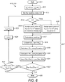
- FIG. 10 in a block diagram, illustrates a computer system in accordance with an embodiment of the invention
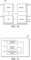
- Figure 11 in a block diagram, illustrates a processor of the computer system of Figure 10 in more detail
- Figures 12a-d in graphs, illustrates the progressive splitting of leaf nodes to provide progressive encoding of colored data in accordance with an aspect of an embodiment of the invention
- FIG. 13 is a block diagram of an exemplary embodiment of a mobile device
- FIG. 14 is a block diagram of an exemplary embodiment of a communication subsystem component of the mobile device of FIG. 13 ;
- MCQ supports progressive refinement of color information in contrast to resolution refinement, it only achieves a compression ratio comparable to GIF or PNG format.
- Chen et al. X. Chen, S. Kwong, and J. Feng, "A new compression scheme for color-quantized images," IEEE Transactions on Circuits and System for Video Technology, Vol. 12, No. 10, pp. 904 ⁇ 908, Oct. 2002 , hereinafter referred to as [2]
- [2] proposed a new color refinement scheme based on MCQ and the distortion-based hierarchical splitting color quantization algorithm pioneered by Orchard and Bouman ( M. Orchard and C.
- the color splitting algorithm in [2], [3] splits a representative color based on a distortion criterion only and does not consider the rate constraint at all.
- each color in a palette image is a 3-D vector.
- Color quantization or color splitting is essentially a vector quantization (VQ) problem ( Y, Linde, A, Buzo, and R. Gray, "An algorithm for vector quantizer design," IEEE Trans. Communications, Vol. COM-28, No. 1, pp. 84-95, Jan. 1980 , hereinafter referred to as [4]).
- VQ vector quantization
- ECVQ conditional entropy constrained vector quantization
- Chou et al. P. Chou, T.
- Section III in accordance with another embodiment, a pixel-wise conditional entropy constrained color splitting algorithm using a fixed Lagrangian multiplier is described.
- Section IV a color-wise conditional entropy constrained color splitting algorithm is presented according to another embodiment, which adds a restriction that all the pixels with the same color value in the original image can be updated by the same representative color values during the splitting process.
- a binary tree structure which can preserve more correlation between color indices than a linear structure, is used in [2] and [3] to represent the relationship of the colors of a palette image for the purpose of partitioning the color map, or equivalently, splitting a representative color progressively during the encoding process.
- Each color vector (or called color entry) c ⁇ corresponds to a color value ( r i , g i , b i ).
- f ( c i ) be defined as the occurrence number of c ⁇ in the given image.
- Our goal is to design a binary tree-based color splitting algorithm that minimizes the distortion subject to an unconditional entropy constraint.
- a color splitting algorithm partitions the color map C or splits the representative color of C progressively until the original palette image is losslessly reconstructed or a user-specified target number of colors is reached.
- q n the representative color of S n that is defined as the centroid of S n .
- the dynamic binary tree together with q n , 0 ⁇ n ⁇ N , gives rise to a tree-structured vector quantizer such that as the dynamic binary tree grows, the current vector quantizer is fully embedded into a subsequent high rate vector quantizer.
- a key question is how to grow the dynamic binary tree.
- T N be a binary tree having N leaf nodes and T N +1 a binary tree generated from T N by splitting a leaf node n of T N into two child nodes n' and n".
- Algorithm 1 Unconditional entropy constrained color splitting algorithm with a fixed ⁇ .
- Step 2 - find the minimum achievable cost for splitting each leaf node.
- Step 4 - progressively transmitting (or merely encoding and then, say, storing) the color updating bits.
- Algorithm 1 employs a fixed ⁇ , which has the physical meaning of the slope of the distortion-rate function.
- Another approach is to use a variable ⁇ and perform the splitting so as to find a good trade-off between the overall distortion decrease and rate increase.
- ⁇ D N - D N + 1 R N + 1 - R N , over all possible iterations at each leaf node of T N and across all leaf nodes of T N .
- ⁇ D N - D N + 1 R N + 1 - R N
- the splitting begins with the assumption that ⁇ is zero. The two representative colors that minimize (1) for this value of ⁇ are found. The decrease in distortion and increase in rate are calculated. The new value of ⁇ is the ratio of the decrease in distortion to the increase in rate. The splitting is now redone with this new value of ⁇ . This iterative process continues until ⁇ does not increase. The converged value is then regarded as the maximum achievable ⁇ at this leaf node. The actual leaf node to be split is the one giving rise to the maximum converged value across all leaf nodes of T N . Algorithm 2 below gives the detailed description.
- Algorithm 2 Unconditional entropy constrained color splitting algorithm with a dynamically determined ⁇ .
- Step 2 - find the maximum achievable ⁇ for each new leaf node.
- the first iteration splits the leaf node n using the distortion-based spitting algorithm discussed in [2].
- f ( S n' ) and f ( S n" ) are also unknown for the first iteration, the algorithm works fine since ⁇ n t is assumed to be zero for the first iteration.
- Step 4 - progressively transmitting (or merely encoding and then, say, storing) the color updating bits.
- Conditional entropy constrained color splitting pixel-wise splitting
- context-based arithmetic coding like the one used in [2] is usually employed to encode the update bits in the entropy coding stage in Algorithms 1 and 2 so as to obtain a high compression gain.
- the rate constraint used is an unconditional entropy. If we could use a conditional entropy as the constraint in a color splitting algorithm, the entropy used in the splitting process would match the entropy of the encoding stage more accurately. Consequently, better results in the rate-distortion sense can be obtained.
- Pixel-wise splitting means pixels with the same color in the original image may be mapped to different leaf nodes during the splitting process. In other words, pixels with the same color in the original image may be updated by different representative colors during the splitting process based on different context. For a palette image with M distinct colors, in general, the original image may not be perfectly reconstructed after M - 1 steps of node splitting even though the original palette image can be losslessly reconstructed eventually.
- color-wise splitting means all the pixels with the same color in the original image must be mapped to the same node during the splitting process.
- conditional entropy constrained color splitting algorithm The main difference between the unconditional entropy constrained color splitting algorithm and conditional entropy constrained color splitting algorithm is the calculation of the increase of entropy rate ⁇ R N shown in (4) and the biased distortion measure as shown in (6).
- conditional entropy rate we may use an arbitrary number of neighboring pixels for the context modeling purpose. In what follows, we calculate the conditional entropy rate conditioned on the left and upper pixels only. The extension to more neighboring pixels is straightforward.
- a pixel-wise conditional entropy constrained color splitting algorithm updates the color information in a pixel-wise manner.
- Let c p be the original color of pixel p in C and denote ⁇ n as the pixel set corresponding to the leaf node n during the splitting process.
- Pixel-wise conditional entropy constrained color splitting algorithm is summarized as follows.
- Algorithm 3 Pixel-wise conditional entropy constrained color splitting algorithm with fixed ⁇ .
- Step 2 - find the minimum achievable cost for splitting each leaf node.
- Step 4 - progressively transmitting (or merely encoding and then, say, storing) the color updating bits.
- Pixel-wise splitting means the pixels with the same color value in the original image may be updated to their final color through different intermediate representative colors.
- the pixels with the same color in the original image may be mapped to different nodes during the splitting process.
- Algorithm 4 Color-wise conditional entropy constrained color splitting algorithm with a fixed ⁇ .
- Step 2 - find the minimum achievable cost for splitting each leaf node.
- Step 4 - progressively transmitting (or merely encoding and then, say, storing) the color updating bits.
- Algorithms 1, 3, and 4 all employ a fixed Lagrangian multiplier ⁇ representing a trade-off between distortion and entropy rate.
- Process 110 shows the steps common to these three algorithms.
- Process 110 begins at step 111 and immediately progresses to step 112 where the splitting process is initialized. Step 112 will be described in greater detail below with reference to FIG. 3 .
- the Lagrangian multiplier ⁇ is selected at step 113. The first iteration of sub-process 127 then begins.
- Each iteration of sub-process 127 splits a leaf node n by creating two new leaf nodes n ' and n " and progressively encodes the new representative colors for the new leaf nodes as well as information regarding which pixels in the image should be updated using these colors. Once n is split, it becomes a non-leaf node.
- the first objective of sub-process 127 is to determine which leaf node must be split. This is done in steps 114-118.
- a leaf node index n is initialized to 0.
- Leaf node n (the leaf node with index n) is then split according to the splitting process in algorithm 1, 3, or 4 at step 115.
- Each of these splitting processes are described in greater detail below with reference to FIG. 4 , 7 and 8 respectively.
- Each of these processes includes the determination of a minimum cost for splitting node n into two new leaf nodes based on the associated change in distortion and the associated increase in the entropy rate.
- sub-process 127 determines whether or not all leaf nodes in the tree structure have been split at step 117 using the variable N, representing the number of leaf nodes in the tree structure, which is initialized at step 314 of process 310 described below with reference to FIG. 3 . If all N leaf nodes have not been split, leaf node index n is incremented by one at step 116 and process 110 returns to step 115 to continue the splitting process. Once all leaf nodes in the tree structure have been split, process 110 continues to step 118. At step 118, the leaf node n which achieves the lowest minimum cost among all the leaf nodes is selected.
- leaf node n is split according to the splitting process in algorithm 1, 3, or 4 at step 119.
- algorithm 1, 3, or 4 Each of these splitting algorithms are described in greater detail below with reference to FIG. 4 , 7 and 8 respectively.
- leaf node n becomes a non-leaf node and two new leaf nodes, n ' and n ", are created.
- leaf nodes n ' and n " are labeled as new leaf nodes.
- Step 121 the new representative colors are progressively encoded along with the color updating bits. Step 121 will be described in greater detail below with reference to FIG. 9 .
- the entropy rate for the new tree structure which includes n ' and n " is calculated by adding the entropy rate for the old tree structure before n was split and the increase in entropy caused by the splitting of n into n ' and n ".
- the entropy rate for the new tree structure may be compared to a target entropy rate set during the initialization process described below with reference to FIG. 3 .
- the number of representative colors which corresponds to the number of leaf nodes in the new tree structure, is compared to a target number of colors set during the initialization process described below with reference to FIG. 3 . If the new entropy rate is greater than or equal to the target entropy rate or if the number of colors in the new tree structure is greater than or equal to the target number of colors then process 110 proceeds to step 126 and terminates. Otherwise, process 110 continues to step 124.
- the distortion for the new tree structure is calculated as the sum of the distortion of the tree structure before node n was split and the decrease is distortion resulting from splitting node n into leaf nodes n ' and n".
- the number of leaf nodes in the tree structure N is then incremented by one at step 125, the process returns to step 114 and the splitting process continues.
- Process 210 functions similarly to process 110 except that process 210 employs a dynamically determined Lagrangian multiplier rather than a fixed Lagrangian multiplier as in process 110.
- Process 210 begins at step 211 and immediately progresses to step 212 where the splitting process is initialized. Step 212 will be described in greater detail with reference to FIG. 3 . The first iteration of sub-process 227 then begins.
- Each iteration of sub-process 227 splits a leaf node n by creating two new leaf nodes n ' and n" and progressively encodes the new representative colors for the new leaf nodes along with information regarding which pixels in the image should be updated using these colors. Once n is split, it becomes a non-leaf node.
- the first objective of sub-process 227 is to determine which leaf node must be split. This is done in steps 214-218.
- a leaf node index n is initialized to 0.
- Leaf node n (the leaf node with index n ) is then tentatively split according to the tentative splitting process for algorithm 2 at step 215. This tentative splitting process is described in greater detail below with reference to FIG. 5 .
- the tentative splitting processes includes the determination of a maximum achievable Lagrangian multiplier ⁇ n,max for each leaf node n .
- the process determines whether or not all leaf nodes in the tree structure have been tentatively split at step 217 using the variable N, representing the number of leaf nodes in the tree structure, which is initialized at step 314 of process 310 described below with reference to FIG. 3 . If all N leaf nodes have not been tentatively split, leaf node index n is incremented at step 216, process 210 returns to step 215 and the tentative splitting process continues. Once all N leaf nodes in the tree structure have been tentatively split, process 210 proceeds to step 218. At step 218, the leaf node n with the highest maximum achievable Lagrangian multiplier ⁇ n,max, calculated in step 215, is selected.
- leaf node n is permanently split according to the permanent splitting process for algorithm 2 at step 219.
- the permanent splitting process is described in greater detail below with reference to FIG. 6 .
- leaf node becomes a non-leaf node and two new leaf nodes, n' and n", are created.
- leaf nodes n ' and n" are labeled as new leaf nodes.
- step 221 the new representative colors are progressively encoded along with the color updating bits. Step 221 will be described in greater detail below with reference to FIG. 9 .
- the entropy rate for the new tree structure which includes n ' and n" is calculated by adding the entropy rate for the old tree structure before n was split and the increase in entropy caused by the splitting of n into n ' and n".
- the increase in entropy is calculated using equation (4).
- the entropy rate for the new tree structure may be compared to a target entropy rate set during the initialization process described below with reference to FIG. 3 .
- the number of representative colors which corresponds to the number of leaf nodes in the new tree structure, is compared to a target number of colors set during the initialization process described below with reference to FIG. 3 . If the new entropy rate is greater than or equal to the target entropy rate or if the number of colors in the new tree structure is greater than or equal to the target number of colors then process 210 proceeds to step 226 and terminates.
- the distortion for the new tree structure is calculated at step 224 as the sum of the distortion of the tree structure before node n was split and the decrease is distortion resulting from splitting node n into leaf nodes n ' and n".
- the number of leaf nodes in the tree structure N is then incremented at step 225, process 210 returns to step 214 and the splitting process continues.
- Process 310 begins at step 311 and immediately progresses to step 312.
- a target number of colors N target or a target entropy rate R target are specified. These values will be used in steps 123 and 223 of processes 110 and 210 respectively to determine when the splitting process should be terminated.
- a number of variables are then initialized.
- the initial representative color for the starting leaf node is calculated, using equation 5, as the centroid of the original color map for the image.
- the number of leaf nodes in the tree structure, N is initialized to 1 at step 314 and the entropy rate for the initial tree structure is set to 0 in step 315.
- the distortion associated with the initial tree structure is set to be the variance of the original color map for the image at step 316.
- a convergence criterion ⁇ is selected. The convergence criterion is used in steps 422, 622, 723 and 824 of processes 410, 610, 710 and 810 respectively to determine when the splitting process for a node should terminate. These processes will be described in detail below.
- process 410 transforms n into a non-leaf node, creates two new leaf nodes n ' and n" and assigns each color in n to either n ' or n" .
- the set of colors assigned to a node n is denoted as S n .
- Process 410 begins at step 411 and immediately progresses to step 412.
- a cost measurement J n old is initialized to the value attained by adding the distortion of the current tree structure to a product obtained by multiplying the entropy rate of the current tree structure by the Lagrangian multiplier ⁇ selected in step 113 of process 110.
- an iterative index t used to keep track of the number of iterations of sub-process 427, is initialized to 0.
- n ' and n" a number of values are calculated based on n ' and n" .
- the new representative colors for n ' and n', q n' and q n" are calculated at step 417.
- the number of occurrences in the original image of each color in n ' and n", f(S n' ) and f(S n" ) respectively are updated.
- the reduction in distortion resulting from splitting node n into n ' and n", ⁇ D N is calculated using equation (3).
- the increase in entropy rate resulting from splitting node n into n ' and n", ⁇ R N is calculated using equation (4).
- the values of ⁇ D N and ⁇ R N calculated in steps 419 and 420 respectively are used to calculate a cost measure J n new representing the cost of the new tree structure.
- the convergence criterion ⁇ selected in step 317 of process 310, is used to determine whether sub-process 427 should be terminated. If the change in cost resulting from the most recent split, calculated as the difference between J n new and J n old divided by J n old , is less than or equal to the convergence criterion ⁇ then another iteration of sub-process 427 is not required and the process 410 proceeds to step 426 and terminates. Otherwise, process 410 proceeds to step 423.
- step 423 the sets of colors assigned to n ' and n", S n' and S n" respectively, are examined to determine if either set includes only one color. If either set S n' or S n" does include only one color then process 410 proceeds to step 426 and terminates. If both S n' and S n" include more than one color, sub-process 427 will be repeated by incrementing iterative index t by one, at step 424, setting J n old to the value of J n new at step 425, and returning to step 414.
- process 510 determines the maximum value for a Lagrangian multiplier ⁇ n,max if n were split into two new leaf nodes n ' and n" and each color in n were assigned to n ' or n" .
- the set of colors assigned to a node n is denoted as S n .
- Process 510 begins at step 511 and immediately progresses to step 512.
- an iterative index t used to keep track of the number of iterations of sub-process 527, is initialized to 0.
- the value of ⁇ t n representing the dynamically determined Lagrangian multiplier for node n and iteration t of sub-process 527 is initialized to 0 at step 513.
- n ' and n" a number of values are calculated based on n ' and n" .
- First the new representative colors for n ' and n', q n' and q n" are calculated at step 517.
- the number of occurrences in the original image of each color in n ' and n", f(S n' ) and f(S n" ) respectively, are calculated.
- the reduction in distortion resulting from splitting node n into n' and n", ⁇ D N is calculated using equation (3).
- the increase in entropy rate resulting from splitting node n into n ' and n", ⁇ R N is calculated using equation (4).
- the decrease in distortion, ⁇ D N divided by the increase in entropy rate, ⁇ R N is compared to the Lagrangian multiplier ⁇ t n, . If ⁇ D N / ⁇ R N is less than or equal to ⁇ t n then the maximum achievable Lagrangian multiplier for node n, ⁇ n,max is set to ⁇ t n at step 522 and process 510 proceeds to step 526 and terminates. If ⁇ D N / ⁇ R N is greater than ⁇ t n then process 510 proceeds to step 523.
- step 523 the sets of colors assigned to n ' and n", S n' and S n" respectively, are examined to determine if either set includes only one color. If either set S n' or S n" does include only one color then process 510 proceeds to step 522 where the maximum achievable Lagrangian multiplier for node n, ⁇ n,max , is set to ⁇ t n at step 522 and process 510 proceeds to step 526 and terminates. If both S n' and S n" includes more one color, sub-process 527 will be repeated by incrementing iterative index t by one, at step 524, setting ⁇ t n to be ⁇ D N / ⁇ R N at step 525, and returning to step 514.
- process 610 transforms n into a non-leaf node, creates two new leaf nodes n ' and n" and assigns each color in n to either n ' or n" .
- the set of colors assigned to a node n is denoted as S n .
- Process 610 begins at step 611 and immediately progresses to step 612.
- a cost measurement J old is initialized to the value attained by adding the distortion of the current tree structure, D N , to a product obtained by multiplying the entropy rate of the current tree structure by the Lagrangian multiplier ⁇ n,max determined in step 218 of process 210.
- an iterative index t used to keep track of the number of iterations of sub-process 627, is initialized to 0.
- n ' and n" a number of values are calculated based on n ' and n" .
- First the new representative colors for n ' and n', q n' and q n" are calculated at step 617.
- the number of occurrences in the original image of each color in n ' and n", f(S n' ) and f(S n" ) respectively, are calculated.
- the reduction in distortion resulting from splitting node n into n ' and n", ⁇ D N is calculated using equation (3).
- the increase in entropy rate resulting from splitting node n into n ' and n", ⁇ R N is calculated using equation (4).
- the values of ⁇ D N and ⁇ R N calculated in steps 619 and 620 respectively are used to calculate a cost measure J new representing the cost of the new tree structure.
- the convergence criterion ⁇ selected in step 317 of process 310, is used to determine whether sub-process 627 should be terminated. If the change in cost resulting from the most recent split, calculated as the difference between J new and J old divided by J old , is less than or equal to the convergence criterion ⁇ then another iteration of sub-process 627 is not required and the process 610 proceeds to step 626 and terminates. Otherwise, process 610 proceeds to step 623.
- step 623 the sets of colors assigned to n ' and n", S n' and S n" respectively, are examined to determine if either set includes only one color. If either set S n' or S n" does include only one color then process 610 proceeds to step 626 and terminates. If both S n' and S n" include more than one color, sub-process 627 will be repeated by incrementing iterative index t by one at step 624, setting J old to the value of J new at step 625, and returning to step 614.
- each leaf node n has a corresponding set of pixels, denoted ⁇ n .
- Process 710 transforms n into a non-leaf node, creates two new leaf nodes n ' and n" and assigns each pixel in ⁇ n to either n ' or n" .
- Process 710 begins at step 711 and immediately progresses to step 712.
- a cost measurement J n old is initialized to the value attained by adding the distortion of the current tree structure to a product obtained by multiplying the entropy rate of the current tree structure by the Lagrangian multiplier ⁇ selected in step 113 of process 110.
- an iterative index t used to keep track of the number of iterations of sub-process 728, is initialized to 0.
- n ' and n" a number of values are calculated based on n ' and n" .
- First the new representative colors for n ' and n", q n' and q n" are calculated at step 717.
- f u,v ( ⁇ n ' ) and f u,v ( ⁇ n" ) are updated where u and v are the representative color indices of the left and upper neighboring pixels of a pixel p in the current reconstructed image and f u,v ( ⁇ n ) is the number of pixels mapped to the leaf node n under context u and v .
- H n ⁇ u , v and H n ⁇ u , v , , the entropy rates of mapping each p ⁇ ⁇ n to n' or n" under context u and v are calculated using equations (10) and (11) respectively.
- the reduction in distortion resulting from splitting node n into n ' and n", ⁇ D N is calculated using equation (13).
- the increase in entropy rate resulting from splitting node n into n ' and n ", denoted ⁇ R N is calculated using equation (14) which takes into account the entropy values calculated in step 719.
- the values of ⁇ D N and ⁇ R N calculated in steps 720 and 721 respectively are used to calculate a cost measure J n new representing the cost of the new tree structure.
- the convergence criterion ⁇ selected in step 317 of process 310, is used to determine whether sub-process 728 should be terminated. If the change in cost resulting from the most recent split, calculated as the difference between J n new and J n old divided by J n old , is less than or equal to the convergence criterion ⁇ then another iteration of sub-process 728 is not required and the process 710 proceeds to step 727 and terminates. Otherwise, process 710 proceeds to step 724.
- step 724 the sets of pixels assigned to n ' and n ", ⁇ n' and ⁇ n" respectively, are examined to determine if either set includes only one pixel. If either set ⁇ n' or ⁇ n" does include only one pixel then process 710 proceeds to step 727 and terminates. If both ⁇ n' and ⁇ n" include more than one pixel, sub-process 728 will be repeated by incrementing iterative index t by one, at step 725, setting J n old to the value of J n new at step 726, and returning to step 714.
- each leaf node n has a corresponding set of pixels, denoted ⁇ n as well as a corresponding set of colors, S n .
- Process 810 transforms n into a non-leaf node, creates two new leaf nodes n ' and n " and assigns each color in n to either n ' or n" .
- Process 810 begins at step 811 and immediately progresses to step 812.
- a cost measurement J n old is initialized to the value attained by adding the distortion of the current tree structure to a product obtained by multiplying the entropy rate of the current tree structure by the Lagrangian multiplier ⁇ selected in step 113 of process 110.
- an iterative index t used to keep track of the number iterations of sub-process 829, is initialized to 0.
- n ' and n" a number of values are calculated based on n ' and n" .
- First the new representative colors for n ' and n", q n' and q n" are calculated at step 817.
- f u,v ( ⁇ n' ) and f u,v ( ⁇ n" ) are updated where f u,v ( ⁇ n ) is the number of pixels assigned to node n under context u and v .
- the entropy rates of mapping each p ⁇ ⁇ n to n' or n" under context u and v are calculated using equations (10) and (11) respectively.
- step 820 the increase in entropy per pixel resulting from the assignment of c i to n ' where c i ⁇ S n is calculated using equation (15) and the same is done for n" using equation (16).
- step 821 the reduction in distortion resulting from splitting node n into n ' and n", ⁇ D N , is calculated using equation (3).
- step 822 the increase in entropy rate resulting from splitting node n into n ' and n", ⁇ R N is calculated using equation (14) which takes into account the entropy values calculated in step 819.
- the values of ⁇ D N and ⁇ R N calculated in steps 821 and 822 respectively, are used to calculate a cost measure J n new representing the cost of the new tree structure.
- the convergence criterion ⁇ selected in step 317 of process 310, is used to determine whether sub-process 829 should be terminated. If the change in cost resulting from the most recent split, calculated as the difference between J n new and J n old divided by J n old , is less than or equal to the convergence criterion ⁇ then another iteration of sub-process 829 is not required and the process 810 proceeds to step 828 and terminates. Otherwise, process 810 proceeds to step 825.
- step 825 the sets of colors assigned to n ' and n", S n' and S n" respectively, are examined to determine if either set includes only one color. If either set S n' or S n" does include only one color then process 810 proceeds to step 828 and terminates. If both S n' and S n" include more than one color, sub-process 829 will be repeated by incrementing iterative index t by one at step 826, setting J n old to the value of J n new at step 827, and returning to step 814.
- Process 910 begins at step 911 and immediately proceeds to step 912 where the node index of the node n, which was selected to be split at step 118 of process 110 or at step 218 of process 210, is encoded.
- step 913 the representative colors of n ' and n", q n' and q n" , are encoded.
- a pixel index i used to keep track of which pixel is currently being considered by sup-process 922, is initialized to 0.
- Process 910 then enters the first iteration of sub-process 922.
- process 910 determines whether pixel i or the color from the original color palette corresponding to pixel i was assigned to n ' or to n " during step 119 of process 110 or step 219 of process 210. If pixel i or the color from the original color palette corresponding to pixel i was assigned to n ' then the color updating bit corresponding to pixel i is encoded as 1. Otherwise, pixel i or the color from the original color palette corresponding to pixel i must have been assigned to n" then the color updating bit corresponding to pixel i is encoded as 0.
- Process 910 then proceeds to step 919 where it is determined whether all the pixels in the original image have been considered by sub-process 922. If not, the pixel index i is incremented by one in step 920 and process 910 returns to step 915. If all the pixels from the original image have been considered by sub-process 922 then process 910 proceeds to step 921 and terminates.
- the encoded information can be used to update the color of all the pixels assigned to n (in the case of algorithm 3) or all the pixels whose color is assigned to n (in the case of algorithms 1, 2 and 4). If the color updating bit associated with pixel p is 1 then p will be updated to the representative color q n' in the current reconstructed image. If the color updating bit associated with pixel p is 0 then p will be updated to the representative color q n" in the current reconstructed image.
- the computer system 1010 comprises a memory 1012 for storing color image data, a monitor 1014 for displaying digital color images, a CPU 1016 for image processing and for providing progressive encoding of color data based on both distortion and entropy rate, and an encoder 1018 for encoding the color image data.
- the encoded color image data can be stored, or can be transmitted from the computer system 1010 via transmission conduit 1020.
- the CPU 1016 of Figure 10 is illustrated in more detail. Specifically, as shown the CPU 1016 comprises a tree management module 1122, a distortion quantizer 1124 and an entropy rate quantizer 1126. As shown, the tree management module 1122 is linked to both the distortion quantizer 1124 and the entropy rate quantizer 1126.
- the tree management module 1122 is operable to perform operations on a tree structure, such as, for example, both initializing the tree structure by dividing up the colors between the initial starting leaf nodes, which may be just the root node, or, alternatively a plurality of starting leaf nodes and subsequently growing the tree structure.
- a tree structure such as, for example, both initializing the tree structure by dividing up the colors between the initial starting leaf nodes, which may be just the root node, or, alternatively a plurality of starting leaf nodes and subsequently growing the tree structure.
- the process of growing the tree structure is based on both entropy rate and distortion; hence, the tree management module 1122 can be linked to both the entropy rate quantizer 1126 and the distortion quantizer 1124.
- the tree management module 1122 can experiment with a particular leaf node by allocating a color in that leaf node to one, or the other, of two new leaf nodes resulting from splitting that original leaf node. Based on both the entropy rate and distortion respectively determined by the entropy rate quantizer 1126 and the distortion quantizer 1124, the tree management module 1122 can determine a particular color allocation between two new leaf nodes of all the colors in the prospective parent node for those two new leaf nodes.
- the tree management module 1122 can determine both the particular leaf node to be divided, as well as the color allocation between the two new leaf nodes resulting from this division.
- the tree management module 1122 can also perform other functions, such as, for example, determining representative colors for new leaf nodes, and maintaining a running count of the total number of leaf nodes.
- the same color in different pixel positions may be assigned to different leaf nodes as leaf node assignment is conducted on a pixel-by-pixel basis, determined both by the context of the particular pixel and color pairs.
- the operation of entropy rate quantizer 1126 and distortion quantizer 1124 is analogous to that described above. Specifically, whether it is a color or a pixel being allocated to a particular new leaf node in a pair of new leaf nodes, the entropy rate quantizer will determine the marginal increase in entropy rate resulting from this assignment, while the distortion quantizer determines any change in distortion.
- how the change in entropy rate for example, is determined will be different in Algorithm 3 as this will also depend on how neighboring pixels are assigned between the respective new leaf nodes.
- FIG. 12a-d the process of progressively splitting leaf nodes to provide progressive encoding of color data is illustrated in a sequence of graphs.
- a root node 1200 is provided in the graph of Figure 12a . All of the colors in the M distinct colors of the original digitized color image are included in this root node.
- the root node 1200 is split into two new leaf nodes 1202 and 1204. With this initial division of the root node 1200, there was, of course, no choice about the particular leaf node to be divided, there being only one node.
- the allocation of all of the M distinct colors in the root node between the new leaf nodes 1202 and 1204 is jointly based on entropy rate and distortion criteria as described above.
- the entropy rate quantizer 1126 can determine a marginal increase in entropy rate for allocating a particular color to either of the new leaf nodes 1202 and 1204.
- the distortion quantizer 1124 can determine a new distortion measure for allocating this color to each of the new leaf nodes 1202 and 1204.
- An associated biased distortion measure based on both rate and distortion can then be determined for each of the leaf nodes 1202 and 1204, and the color can then be allocated to which ever of leaf nodes 1202 and 1204 has a lower associated biased distortion measure.
- leaf node 1202 and leaf node 1204 The transition from the graph of Figure 12b to the graph of Figure 12c is more complicated as in this instance there are two leaf nodes, leaf node 1202 and leaf node 1204, to choose between dividing. Again, the decision of which of leaf nodes 1202 or 1204 to divide is based on both distortion and entropy rate considerations. According to some embodiments (see Algorithms 1, 3 and 4 described above) of the present invention where a fixed Lagrangian multiplier is employed, a cost for turning that leaf node into a non-leaf node linked to two new leaf nodes (dividing the leaf node) is determined. Then, whichever of the leaf nodes 1202 and 1204 has the lower cost, will be divided.
- the trade-off or Lagrangian multiplier will be determined for each possible leaf node. Then, whichever of the leaf nodes 1202 and 1204 achieves a larger Lagrangian multiplier (i.e., the best trade-off between distortion decrease and entropy rate increase), will be divided.
- the cost for dividing each of the leaf nodes 1202 and 1204 is generally determined by the entropy rate quantizer 1126 and the distortion quantizer 1124. That is, the entropy rate quantizer 1126 can determine an associated increase in entropy rate resulting from turning a particular leaf node into a non-leaf node linked to two new leaf nodes, while the distortion quantizer 1124 can determine an associated change in distortion resulting from turning this leaf node into a non-leaf node. Of course, in the case of each leaf node, this will also be an iterative process as different color allocations between the new leaf nodes are tested.
- leaf node 1202 is divided into two non-leaf nodes 1206 and 1208.
- leaf nodes 1204, 1206 and 1208 remain: leaf nodes 1204, 1206 and 1208.
- the Lagrangian multiplier may not be fixed. In that case, a Lagrangian multiplier can be determined for each of the leaf nodes 1202 and 1204 of Figure 12b . Then, the leaf node that has a larger achievable Lagrangian multiplier can be divided.
- leaf node division or tree growth in the transition between Figure 12c and Figure 12d is quite similar to that between Figures 12b and 12c .
- the leaf nodes under consideration for division are leaf nodes 1204, 1206, and 1208.
- leaf node 1206 has been divided to create two new leaf nodes 1210 and 1212.
- four leaf nodes 1204, 1208, 1210 and 1212 now exist.
- This process of leaf node division can continue until some target point is reached. This target point may be based on the total entropy rate or, alternatively, may be based on the total number of leaf nodes resulting from the last division.
- each time a leaf node is divided there is an associated increased entropy rate.
- the total entropy rate associated with the binary tree may exceed a target entropy rate.
- the total number of leaf nodes is increased by one.
- the new total number of leaf nodes in the tree structure may exceed some target number of leaf nodes.
- This target number of leaf nodes may be M (the number of colors in the original digitized color image) such that the original digitized color image can be completely reproduced for color-wise splitting algorithm (i.e., Algorithms 1, 2 and 4).
- this target number of leaf nodes may be less than M.
- the process of tree growth or leaf node division will cease when either the associated total entropy rate exceeds the target entropy rate or the total number of leaf nodes exceeds the target number of leaf nodes.
- a mobile wireless communication device can be used to provide entropy-constrained color splitting as described above.
- the embodiments described below generally relate to such a mobile wireless communication device, hereafter referred to as a mobile device, which can be configured according to an IT policy.
- IT policy in general, refers to a collection of IT policy rules, in which the IT policy rules can be defined as being either grouped or non-grouped and global or per-user.
- the terms grouped, non-grouped, global and per-user are defined further below.
- Examples of applicable communication devices include pagers, cellular phones, cellular smart-phones, wireless organizers, personal digital assistants, computers, laptops, handheld wireless communication devices, wirelessly enabled notebook computers and the like.
- the mobile device is a two-way communication device with advanced data communication capabilities including the capability to communicate with other mobile devices or computer systems through a network of transceiver stations.
- the mobile device may also have the capability to allow voice communication.
- it may be referred to as a data messaging device, a two-way pager, a cellular telephone with data messaging capabilities, a wireless Internet appliance, or a data communication device (with or without telephony capabilities).
- FIGS. 13 and 14 To aid the reader in understanding the structure of the mobile device and how it communicates with other devices and host systems, reference will now be made to FIGS. 13 and 14 .
- the mobile device 1300 includes a number of components such as a main processor 1302 that controls the overall operation of the mobile device 1300. Communication functions, including data and voice communications, are performed through a communication subsystem 1304.
- the communication subsystem 1304 receives messages from and sends messages to a wireless network 1400.
- the communication subsystem 1304 is configured in accordance with the Global System for Mobile Communication (GSM) and General Packet Radio Services (GPRS) standards.
- GSM Global System for Mobile Communication
- GPRS General Packet Radio Services
- the GSM/GPRS wireless network is used worldwide and it is expected that these standards will be superseded eventually by Enhanced Data GSM Environment (EDGE) and Universal Mobile Telecommunications Service (UMTS). New standards are still being defined, but it is believed that they will have similarities to the network behavior described herein, and it will also be understood by persons skilled in the art that the embodiments described herein are intended to use any other suitable standards that are developed in the future.
- the wireless link connecting the communication subsystem 1304 with the wireless network 1400 represents one or more different Radio Frequency (RF) channels, operating according to defined protocols specified for GSM/GPRS communications. With newer network protocols, these channels are capable of supporting both circuit switched voice communications and packet switched data communications.
- RF Radio Frequency
- wireless network 1400 associated with mobile device 1300 is a GSM/GPRS wireless network in one exemplary implementation
- other wireless networks may also be associated with the mobile device 1300 in variant implementations.
- the different types of wireless networks that may be employed include, for example, data-centric wireless networks, voice-centric wireless networks, and dual-mode networks that can support both voice and data communications over the same physical base stations.
- Combined dual-mode networks include, but are not limited to, Code Division Multiple Access (CDMA) or CDMA2000 networks, GSM/GPRS networks (as mentioned above), and future third-generation (3G) networks like EDGE and UMTS.
- Some other examples of data-centric networks include WiFi 802.11, Mobitex TM and DataTAC TM network communication systems.
- Examples of other voice-centric data networks include Personal Communication Systems (PCS) networks like GSM and Time Division Multiple Access (TDMA) systems.
- PCS Personal Communication Systems
- TDMA Time Division Multiple Access
- the main processor 1302 also interacts with additional subsystems such as a Random Access Memory (RAM) 1306, a flash memory 1308, a display 1310, an auxiliary input/output (I/O) subsystem 1312, a data port 1314, a keyboard 1316, a speaker 1318, a microphone 1320, short-range communications 1322 and other device subsystems 1324.
- RAM Random Access Memory
- flash memory 1308 a flash memory 1308
- I/O auxiliary input/output subsystem
- data port 1314 a keyboard 1316
- speaker 1318 a speaker 1318
- microphone 1320 short-range communications 1322 and other device subsystems 1324.
- the display 1310 and the keyboard 1316 may be used for both communication-related functions, such as entering a text message for transmission over the network 1400, and device-resident functions such as a calculator or task list.
- the mobile device 1300 can send and receive communication signals over the wireless network 1400 after required network registration or activation procedures have been completed.
- Network access is associated with a subscriber or user of the mobile device 1300.
- the mobile device 1300 To identify a subscriber, the mobile device 1300 requires a SIM/RUIM card 1326 (i.e. Subscriber Identity Module or a Removable User Identity Module) to be inserted into a SIM/RUIM interface 1328 in order to communicate with a network.
- SIM/RUIM card 1326 is one type of a conventional "smart card” that can be used to identify a subscriber of the mobile device 1300 and to personalize the mobile device 1300, among other things. Without the SIM card 1326, the mobile device 1300 is not fully operational for communication with the wireless network 1400.
- SIM card/RUIM 1326 By inserting the SIM card/RUIM 1326 into the SIM/RUIM interface 1328, a subscriber can access all subscribed services. Services may include: web browsing and messaging such as e-mail, voice mail, Short Message Service (SMS), and Multimedia Messaging Services (MMS). More advanced services may include: point of sale, field service and sales force automation.
- the SIM card/RUIM 1326 includes a processor and memory for storing information. Once the SIM card/RUIM 1326 is inserted into the SIM/RUIM interface 1328, it is coupled to the main processor 1302. In order to identify the subscriber, the SIM card/RUIM 1326 can include some user parameters such as an International Mobile Subscriber Identity (IMSI).
- IMSI International Mobile Subscriber Identity
- SIM card/RUIM 1326 An advantage of using the SIM card/RUIM 1326 is that a subscriber is not necessarily bound by any single physical mobile device.
- the SIM card/RUIM 1326 may store additional subscriber information for a mobile device as well, including datebook (or calendar) information and recent call information. Alternatively, user identification information can also be programmed into the flash memory 1308.
- the mobile device 1300 is a battery-powered device and includes a battery interface 1332 for receiving one or more rechargeable batteries 1330.
- the battery 1330 can be a smart battery with an embedded microprocessor.
- the battery interface 1332 is coupled to a regulator (not shown), which assists the battery 1330 in providing power V+ to the mobile device 1300.
- a regulator not shown
- future technologies such as micro fuel cells may provide the power to the mobile device 1300.
- the mobile device 1300 also includes an operating system 1334 and software components 1336 to 1346 which are described in more detail below.
- the operating system 1334 and the software components 1336 to 1346 that are executed by the main processor 1302 are typically stored in a persistent store such as the flash memory 1308, which may alternatively be a read-only memory (ROM) or similar storage element (not shown).
- a persistent store such as the flash memory 1308, which may alternatively be a read-only memory (ROM) or similar storage element (not shown).
- ROM read-only memory
- portions of the operating system 1334 and the software components 1336 to 1346, such as specific device applications, or parts thereof, may be temporarily loaded into a volatile store such as the RAM 1306.
- Other software components can also be included, as is well known to those skilled in the art.
- the subset of software applications 1336 that control basic device operations, including data and voice communication applications, will normally be installed on the mobile device 1300 during its manufacture.
- Other software applications include a message application 1338 that can be any suitable software program that allows a user of the mobile device 1300 to send and receive electronic messages.
- Messages that have been sent or received by the user are typically stored in the flash memory 1308 of the mobile device 1300 or some other suitable storage element in the mobile device 1300.
- some of the sent and received messages may be stored remotely from the device 1300 such as in a data store of an associated host system that the mobile device 1300 communicates with.
- the software applications can further include a device state module 1340, a Personal Information Manager (PIM) 1342, and other suitable modules (not shown).
- the device state module 1340 provides persistence, i.e. the device state module 1340 ensures that important device data is stored in persistent memory, such as the flash memory 1308, so that the data is not lost when the mobile device 1300 is turned off or loses power.
- the PIM 1342 includes functionality for organizing and managing data items of interest to the user, such as, but not limited to, e-mail, contacts, calendar events, voice mails, appointments, and task items.
- a PIM application has the ability to send and receive data items via the wireless network 1400.
- PIM data items may be seamlessly integrated, synchronized, and updated via the wireless network 1400 with the mobile device subscriber's corresponding data items stored and/or associated with a host computer system. This functionality creates a mirrored host computer on the mobile device 1300 with respect to such items. This can be particularly advantageous when the host computer system is the mobile device subscriber's office computer system.
- the mobile device 1300 also includes a connect module 1344, and an IT policy module 1346.
- the connect module 1344 implements the communication protocols that are required for the mobile device 1300 to communicate with the wireless infrastructure and any host system, such as an enterprise system, that the mobile device 1300 is authorized to interface with.
- the connect module 1344 includes a set of APIs that can be integrated with the mobile device 1300 to allow the mobile device 1300 to use any number of services associated with the enterprise system.
- the connect module 1344 allows the mobile device 1300 to establish an end-to-end secure, authenticated communication pipe with the host system.
- a subset of applications for which access is provided by the connect module 1344 can be used to pass IT policy commands from the host system to the mobile device 1300. This can be done in a wireless or wired manner.
- These instructions can then be passed to the IT policy module 1346 to modify the configuration of the device 1300. Alternatively, in some cases, the IT policy update can also be done over a wired connection.
- the IT policy module 1346 receives IT policy data that encodes the IT policy.
- the IT policy module 1346 then ensures that the IT policy data is authenticated by the mobile device 1300.
- the IT policy data can then be stored in the flash memory 1306 in its native form. After the IT policy data is stored, a global notification can be sent by the IT policy module 1346 to all of the applications residing on the mobile device 1300. Applications for which the IT policy may be applicable then respond by reading the IT policy data to look for IT policy rules that are applicable.
- the IT policy module 1346 can include a parser (not shown), which can be used by the applications to read the IT policy rules. In some cases, another module or application can provide the parser. Grouped IT policy rules, described in more detail below, are retrieved as byte streams, which are then sent (recursively, in a sense) into the parser to determine the values of each IT policy rule defined within the grouped IT policy rule. In at least some embodiments, the IT policy module 1346 can determine which applications are affected by the IT policy data and send a notification to only those applications. In either of these cases, for applications that aren't running at the time of the notification, the applications can call the parser or the IT policy module 1346 when they are executed to determine if there are any relevant IT policy rules in the newly received IT policy data.
- All applications that support rules in the IT Policy are coded to know the type of data to expect.
- the value that is set for the "WEP User Name” IT policy rule is known to be a string; therefore the value in the IT policy data that corresponds to this rule is interpreted as a string.
- the setting for the "Set Maximum Password Attempts" IT policy rule is known to be an integer, and therefore the value in the IT policy data that corresponds to this rule is interpreted as such.
- the IT policy module 1346 sends an acknowledgement back to the host system to indicate that the IT policy data was received and successfully applied.
- software applications can also be installed on the mobile device 1300.
- These software applications can be third party applications, which are added after the manufacture of the mobile device 1300. Examples of third party applications include games, calculators, utilities, etc.
- the additional applications can be loaded onto the mobile device 1300 through at least one of the wireless network 1400, the auxiliary I/O subsystem 1312, the data port 1314, the short-range communications subsystem 1322, or any other suitable device subsystem 1324.
- This flexibility in application installation increases the functionality of the mobile device 1300 and may provide enhanced on-device functions, communication-related functions, or both.
- secure communication applications may enable electronic commerce functions and other such financial transactions to be performed using the mobile device 1300.
- the data port 1314 enables a subscriber to set preferences through an external device or software application and extends the capabilities of the mobile device 1300 by providing for information or software downloads to the mobile device 1300 other than through a wireless communication network.
- the alternate download path may, for example, be used to load an encryption key onto the mobile device 1300 through a direct and thus reliable and trusted connection to provide secure device communication.
- the data port 1314 can be any suitable port that enables data communication between the mobile device 1300 and another computing device.
- the data port 1314 can be a serial or a parallel port.
- the data port 1314 can be a USB port that includes data lines for data transfer and a supply line that can provide a charging current to charge the battery 1330 of the mobile device 1300.
- the short-range communications subsystem 1322 provides for communication between the mobile device 1300 and different systems or devices, without the use of the wireless network 1400.
- the subsystem 1322 may include an infrared device and associated circuits and components for short-range communication.
- Examples of short-range communication standards include standards developed by the Infrared Data Association (IrDA), Bluetooth, and the 802.11 family of standards developed by IEEE.
- a received signal such as a text message, an e-mail message, or web page download will be processed by the communication subsystem 1304 and input to the main processor 1302.
- the main processor 1302 will then process the received signal for output to the display 1310 or alternatively to the auxiliary I/O subsystem 1312.
- a subscriber may also compose data items, such as e-mail messages, for example, using the keyboard 1316 in conjunction with the display 1310 and possibly the auxiliary I/O subsystem 1312.
- the auxiliary subsystem 1312 may include devices such as: a touch screen, mouse, track ball, infrared fingerprint detector, or a roller wheel with dynamic button pressing capability.
- the keyboard 1316 is preferably an alphanumeric keyboard and/or telephone-type keypad. However, other types of keyboards may also be used.
- a composed item may be transmitted over the wireless network 1400 through the communication subsystem 1304.
- the overall operation of the mobile device 1300 is substantially similar, except that the received signals are output to the speaker 1318, and signals for transmission are generated by the microphone 1320.
- Alternative voice or audio I/O subsystems such as a voice message recording subsystem, can also be implemented on the mobile device 1300.
- voice or audio signal output is accomplished primarily through the speaker 1318, the display 1310 can also be used to provide additional information such as the identity of a calling party, duration of a voice call, or other voice call related information.
- the communication subsystem 1304 includes a receiver 1350, a transmitter 1352, as well as associated components such as one or more embedded or internal antenna elements 1354 and 1356, Local Oscillators (LOs) 1358, and a processing module such as a Digital Signal Processor (DSP) 1360.
- the particular design of the communication subsystem 1304 is dependent upon the communication network 1400 with which the mobile device 1300 is intended to operate. Thus, it should be understood that the design illustrated in FIG. 14 serves only as one example.
- Signals received by the antenna 1354 through the wireless network 1400 are input to the receiver 1350, which may perform such common receiver functions as signal amplification, frequency down conversion, filtering, channel selection, and analog-to-digital (A/D) conversion.
- A/D conversion of a received signal allows more complex communication functions such as demodulation and decoding to be performed in the DSP 1360.
- signals to be transmitted are processed, including modulation and encoding, by the DSP 1360.
- These DSP-processed signals are input to the transmitter 1352 for digital-to-analog (D/A) conversion, frequency up conversion, filtering, amplification and transmission over the wireless network 1400 via the antenna 1356.
- the DSP 1360 not only processes communication signals, but also provides for receiver and transmitter control. For example, the gains applied to communication signals in the receiver 1350 and the transmitter 1352 may be adaptively controlled through automatic gain control algorithms implemented in the DSP 1360.
- the wireless link between the mobile device 1300 and the wireless network 1400 can contain one or more different channels, typically different RF channels, and associated protocols used between the mobile device 1300 and the wireless network 1400.
- An RF channel is a limited resource that must be conserved, typically due to limits in overall bandwidth and limited battery power of the mobile device 1300.
- the transmitter 1352 When the mobile device 1300 is fully operational, the transmitter 1352 is typically keyed or turned on only when it is transmitting to the wireless network 1400 and is otherwise turned off to conserve resources. Similarly, the receiver 1350 is periodically turned off to conserve power until it is needed to receive signals or information (if at all) during designated time periods.
Landscapes
- Engineering & Computer Science (AREA)
- Multimedia (AREA)
- Signal Processing (AREA)
- Compression Of Band Width Or Redundancy In Fax (AREA)
- Compression Or Coding Systems Of Tv Signals (AREA)
- Image Processing (AREA)
- Color Image Communication Systems (AREA)
- Color Television Systems (AREA)
Applications Claiming Priority (2)
| Application Number | Priority Date | Filing Date | Title |
|---|---|---|---|
| US71958505P | 2005-09-23 | 2005-09-23 | |
| EP06790725A EP1927083A4 (de) | 2005-09-23 | 2006-09-25 | Verfahren, system und computerprogrammprodukt zur bereitstellung einer entropie eingeschränkten farbaufteilung für palettenbilder mit farbweiser aufteilung |
Related Parent Applications (1)
| Application Number | Title | Priority Date | Filing Date |
|---|---|---|---|
| EP06790725.3 Division | 2006-09-25 |
Publications (1)
| Publication Number | Publication Date |
|---|---|
| EP2461293A1 true EP2461293A1 (de) | 2012-06-06 |
Family
ID=37888497
Family Applications (4)
| Application Number | Title | Priority Date | Filing Date |
|---|---|---|---|
| EP06790725A Ceased EP1927083A4 (de) | 2005-09-23 | 2006-09-25 | Verfahren, system und computerprogrammprodukt zur bereitstellung einer entropie eingeschränkten farbaufteilung für palettenbilder mit farbweiser aufteilung |
| EP06790730A Ceased EP1927084A4 (de) | 2005-09-23 | 2006-09-25 | Verfahren, system und computerprogrammprodukt zur entropie eingeschränkten farbaufteilung für palettenbilder mit pixelweiser aufteilung |
| EP11181941A Ceased EP2461293A1 (de) | 2005-09-23 | 2006-09-25 | Verfahren, System und Computerprogrammprodukt zur Bereitstellung einer Entropie eingeschränkten Farbaufteilung für Palettenbilder mit farbweiser Aufteilung |
| EP11181942A Ceased EP2461294A1 (de) | 2005-09-23 | 2006-09-25 | Verfahren, System und Computerprogrammprodukt zur Bereitstellung einer entropieeingeschränkten Farbaufteilung für Palettenbilder mit pixelweiser Aufteilung |
Family Applications Before (2)
| Application Number | Title | Priority Date | Filing Date |
|---|---|---|---|
| EP06790725A Ceased EP1927083A4 (de) | 2005-09-23 | 2006-09-25 | Verfahren, system und computerprogrammprodukt zur bereitstellung einer entropie eingeschränkten farbaufteilung für palettenbilder mit farbweiser aufteilung |
| EP06790730A Ceased EP1927084A4 (de) | 2005-09-23 | 2006-09-25 | Verfahren, system und computerprogrammprodukt zur entropie eingeschränkten farbaufteilung für palettenbilder mit pixelweiser aufteilung |
Family Applications After (1)
| Application Number | Title | Priority Date | Filing Date |
|---|---|---|---|
| EP11181942A Ceased EP2461294A1 (de) | 2005-09-23 | 2006-09-25 | Verfahren, System und Computerprogrammprodukt zur Bereitstellung einer entropieeingeschränkten Farbaufteilung für Palettenbilder mit pixelweiser Aufteilung |
Country Status (5)
| Country | Link |
|---|---|
| US (6) | US7903893B2 (de) |
| EP (4) | EP1927083A4 (de) |
| CN (3) | CN102196266B (de) |
| CA (2) | CA2620893C (de) |
| WO (2) | WO2007033483A1 (de) |
Families Citing this family (20)
| Publication number | Priority date | Publication date | Assignee | Title |
|---|---|---|---|---|
| EP1927083A4 (de) | 2005-09-23 | 2009-07-01 | Slipstream Data Inc | Verfahren, system und computerprogrammprodukt zur bereitstellung einer entropie eingeschränkten farbaufteilung für palettenbilder mit farbweiser aufteilung |
| US8775662B2 (en) * | 2005-09-27 | 2014-07-08 | Blackberry Limited | System and method for progressive delivery of multimedia objects |
| US20090010533A1 (en) * | 2007-07-05 | 2009-01-08 | Mediatek Inc. | Method and apparatus for displaying an encoded image |
| KR20100053010A (ko) * | 2008-11-12 | 2010-05-20 | 삼성전자주식회사 | 휴대단말기의 태양 전지 충전을 이용한 어플리케이션 구현 장치 및 방법 |
| US7952504B2 (en) * | 2009-06-19 | 2011-05-31 | Mediatek Inc. | Gain control method and electronic apparatus capable of gain control |
| US9172963B2 (en) | 2010-11-01 | 2015-10-27 | Qualcomm Incorporated | Joint coding of syntax elements for video coding |
| US8830258B2 (en) * | 2011-03-07 | 2014-09-09 | Ricoh Co., Ltd | Generating strokes in real-time on an electronic paper display |
| US9142056B1 (en) * | 2011-05-18 | 2015-09-22 | Disney Enterprises, Inc. | Mixed-order compositing for images having three-dimensional painting effects |
| US9223825B2 (en) | 2012-08-20 | 2015-12-29 | Blackberry Limited | Methods and devices for applying constraints to data object |
| US11323733B2 (en) | 2014-05-23 | 2022-05-03 | Qualcomm Incorporated | Predictor palette initialization in palette-based video coding |
| US10291940B2 (en) | 2014-05-23 | 2019-05-14 | Qualcomm Incorporated | Coding runs with escape in palette-based video coding |
| US10382749B2 (en) | 2014-05-23 | 2019-08-13 | Qualcomm Incorporated | Coding run values based on palette index in palette-based video coding |
| CN104021579A (zh) * | 2014-06-10 | 2014-09-03 | 广州博冠信息科技有限公司 | 图片变色方法及装置 |
| US10136141B2 (en) * | 2014-06-11 | 2018-11-20 | Qualcomm Incorporated | Determining quantization parameter (QP) values and delta QP values for palette coded blocks in video coding |
| US10496313B2 (en) | 2014-09-22 | 2019-12-03 | Hewlett Packard Enterprise Development Lp | Identification of content-defined chunk boundaries |
| EP3007423A1 (de) * | 2014-10-06 | 2016-04-13 | Industrial Technology Research Institute | Verfahren zur farbpalettencodierung zur verwendung mit einer elektronischen vorrichtung und elektronische vorrichtung damit |
| EP3306922A1 (de) * | 2016-10-05 | 2018-04-11 | Thomson Licensing | Verfahren und vorrichtung zur codierung eines bildes |
| US20220358685A1 (en) * | 2019-06-24 | 2022-11-10 | Nippon Telegraph And Telephone Corporation | Image encoding method and image decoding method |
| US11748914B2 (en) * | 2020-08-26 | 2023-09-05 | Meta Platforms Technologies, Llc | Rate controlled image and texture data compression |
| WO2023197832A1 (en) * | 2022-04-13 | 2023-10-19 | Mediatek Inc. | Method and apparatus of using separate splitting trees for colour components in video coding system |
Family Cites Families (9)
| Publication number | Priority date | Publication date | Assignee | Title |
|---|---|---|---|---|
| US5047842A (en) * | 1989-11-03 | 1991-09-10 | The Trustees Of Princeton University | Color image display with a limited palette size |
| JP4420415B2 (ja) * | 1998-07-03 | 2010-02-24 | キヤノン株式会社 | 符号化方法及び符号化装置 |
| US6496198B1 (en) | 1999-05-04 | 2002-12-17 | Canon Kabushiki Kaisha | Color editing system |
| US6496498B1 (en) * | 1999-11-19 | 2002-12-17 | Siemens Information & Communication Mobile Llc | Method and system for avoiding periodic bursts of interference in wireless communication between a mobile unit and a base unit |
| US6868186B1 (en) * | 2000-07-13 | 2005-03-15 | Ceva D.S.P. Ltd. | Visual lossless image compression |
| CN1209925C (zh) * | 2003-01-10 | 2005-07-06 | 李春林 | 基于信源高阶熵的数据压缩方法 |
| CN1322472C (zh) * | 2003-09-08 | 2007-06-20 | 中国人民解放军第一军医大学 | 基于小波变换的预测四叉树图像压缩及解压方法 |
| JP2006333436A (ja) | 2005-01-07 | 2006-12-07 | Ntt Docomo Inc | 動画像符号化装置、動画像復号装置、動画像符号化方法、動画像復号方法、動画像符号化プログラム、及び、動画像復号プログラム |
| EP1927083A4 (de) * | 2005-09-23 | 2009-07-01 | Slipstream Data Inc | Verfahren, system und computerprogrammprodukt zur bereitstellung einer entropie eingeschränkten farbaufteilung für palettenbilder mit farbweiser aufteilung |
-
2006
- 2006-09-25 EP EP06790725A patent/EP1927083A4/de not_active Ceased
- 2006-09-25 CA CA2620893A patent/CA2620893C/en active Active
- 2006-09-25 CN CN2011100543165A patent/CN102196266B/zh active Active
- 2006-09-25 CN CN2006800350935A patent/CN101283377B/zh active Active
- 2006-09-25 WO PCT/CA2006/001558 patent/WO2007033483A1/en active Application Filing
- 2006-09-25 CN CN200680035129XA patent/CN101317197B/zh active Active
- 2006-09-25 US US11/534,942 patent/US7903893B2/en active Active
- 2006-09-25 EP EP06790730A patent/EP1927084A4/de not_active Ceased
- 2006-09-25 EP EP11181941A patent/EP2461293A1/de not_active Ceased
- 2006-09-25 EP EP11181942A patent/EP2461294A1/de not_active Ceased
- 2006-09-25 WO PCT/CA2006/001564 patent/WO2007033487A2/en active Application Filing
- 2006-09-25 CA CA002620885A patent/CA2620885A1/en not_active Abandoned
- 2006-09-25 US US11/534,956 patent/US8000547B2/en active Active
-
2011
- 2011-02-08 US US13/023,135 patent/US8265408B2/en active Active
- 2011-07-20 US US13/186,857 patent/US8260071B2/en active Active
-
2012
- 2012-07-27 US US13/559,854 patent/US8503807B2/en active Active
- 2012-08-03 US US13/565,967 patent/US8559740B2/en active Active
Non-Patent Citations (17)
| Title |
|---|
| A. BUZO, A. GRAY, JR., R. GRAY, J. MARKEL: "Speech coding based upon vector quantization", IEEE TRANS. ACOUS., SPEECH, AND SIGNAL PROCESSING, vol. ASSP-28, no. 5, October 1980 (1980-10-01), pages 562 - 574, XP000670426, DOI: doi:10.1109/TASSP.1980.1163445 |
| BALAKRISHNAN M ET AL: "Variable-rate tree-structured vector quantizers", IEEE TRANSACTIONS ON INFORMATION THEORY, vol. 41, no. 4, 1 July 1995 (1995-07-01), pages 917 - 930, XP002127871, ISSN: 0018-9448 * |
| CHADDHA N ET AL: "Color quantization of images based on human vision perception", PROCEEDINGS OF THE INTERNATIONAL CONFERENCE ON ACOUSTICS, SPEECH, AND SIGNAL PROCESSING, vol. v, 19 April 1994 (1994-04-19), pages 89 - 92, XP010133768, ISBN: 978-0-7803-1775-8 * |
| CHEN, X. CHEN, S. KWONG, J. FENG: "A new compression scheme for color- quantized images", IEEE TRANSACTIONS ON CIRCUITS AND SYSTEM FOR VIDEO TECHNOLOGY, vol. 12, no. 10, October 2002 (2002-10-01), pages 904 - 908, XP001133421, DOI: doi:10.1109/TCSVT.2002.804896 |
| CHOU P A ET AL: "Conditional entropy-constrained vector quantization of linear predictive coefficients", 19900403; 19900403 - 19900406, 3 April 1990 (1990-04-03), pages 197 - 200, XP010642079 * |
| E. RISKIN, R. GRAY: "A greedy tree growing algorithm for the design of variable rate vector quantizers", IEEE TRANSACTIONS ON SIGNAL PROCESSING, vol. 39, no. 11, November 1991 (1991-11-01), pages 2500 - 2507, XP000271457, DOI: doi:10.1109/78.98004 |
| EFFROS M ED - STORER J A ET AL: "Practical multi-resolution source coding: TSVQ revisited", PROCEEDINGS OF DATA COMPRESSION CONFERENCE, 30 March 1998 (1998-03-30) - 1 April 1998 (1998-04-01), pages 53 - 62, XP010276610, ISBN: 978-0-8186-8406-7 * |
| GERSHO ET AL: "Vector quantization and signal compression", VECTOR QUANTIZATION AND SIGNAL COMPRESSION, BOSTON, KLUWER, US, 1 January 1991 (1991-01-01), pages 352 - 355, XP002096148 * |
| GUILLOPE V: "CONDITIONAL ENTROPY-CONSTRAINED VECTOR QUANTIZATION OF CHROMATIC INFORMATION IN DOCUMENT IMAGES", June 2002 (2002-06-01), OTTAWA, ONTARIO, CANADA, XP002523631, Retrieved from the Internet <URL:http://www.site.uottawa.ca/school/research/viva/theses/Guillope_Thesis.pdf> [retrieved on 20090409] * |
| M. MAHESH, W. PEARLMÁN, L. LU: "Variable-rate tree-structured vector quantizers", IEEE TRANS. INFORMATION THEORY, vol. 41, no. 4, July 1995 (1995-07-01), pages 917 - 930, XP002127871, DOI: doi:10.1109/18.391239 |
| M. ORCHARD, C. BOUMAN: "Color quantization of images", IEEE TRANSACTIONS ON SIGNAL PROCESSING, vol. 39, no. 12, December 1991 (1991-12-01), pages 2677 - 2690, XP000275119, DOI: doi:10.1109/78.107417 |
| P. CHOU, T. LOOKABAUGH, R. GRAY: "Entropy-constrained vector quantization", IEEE TRANS. ACOUS., SPEECH, AND SIGNAL PROCESSING, vol. 37, no. 1, January 1989 (1989-01-01), pages 31 - 42 |
| P. CHOU, T. LOOKABAUGH: "Conditional entropy constrained vector quantization", PROCEEDING ICASSP, April 1990 (1990-04-01), pages 197 - 200 |
| U. RAUSCHENBACH, PERTH: "Compression of palettized images with progressive coding of the color information", PROC. SPIE VISUAL COMMUNICATIONS AND IMAGE PROCESSING (VCIP2000, June 2000 (2000-06-01) |
| X. CHEN, S. KWONG, J. FENG: "A new compression scheme for color- quantized images", IEEE TRANSACTIONS ON CIRCUITS AND SYSTEM FOR VIDEO TECHNOLOGY, vol. 12, no. 10, October 2002 (2002-10-01), pages 904 - 908, XP001133421, DOI: doi:10.1109/TCSVT.2002.804896 |
| XIN CHEN ET AL: "A New Compression Scheme for Color-Quantized Images", IEEE TRANSACTIONS ON CIRCUITS AND SYSTEMS FOR VIDEO TECHNOLOGY, vol. 12, no. 10, 1 October 2002 (2002-10-01), pages 904 - 908, XP011071875, ISSN: 1051-8215 * |
| Y, LINDE, A, BUZO, R. GRAY: "An algorithm for vector quantizer design", IEEE TRANS. COMMUNICATIONS, vol. COM-28, no. 1, January 1980 (1980-01-01), pages 84 - 95, XP000563284, DOI: doi:10.1109/TCOM.1980.1094577 |
Also Published As
| Publication number | Publication date |
|---|---|
| WO2007033487A8 (en) | 2008-06-12 |
| EP1927083A4 (de) | 2009-07-01 |
| WO2007033483A1 (en) | 2007-03-29 |
| CN102196266B (zh) | 2013-07-03 |
| US8559740B2 (en) | 2013-10-15 |
| US8260071B2 (en) | 2012-09-04 |
| CA2620885A1 (en) | 2007-03-29 |
| US20120321183A1 (en) | 2012-12-20 |
| EP2461294A1 (de) | 2012-06-06 |
| US7903893B2 (en) | 2011-03-08 |
| CN102196266A (zh) | 2011-09-21 |
| CN101317197A (zh) | 2008-12-03 |
| US8000547B2 (en) | 2011-08-16 |
| WO2007033487A2 (en) | 2007-03-29 |
| US20070076968A1 (en) | 2007-04-05 |
| US20070071339A1 (en) | 2007-03-29 |
| CA2620893A1 (en) | 2007-03-29 |
| EP1927084A2 (de) | 2008-06-04 |
| WO2007033487A3 (en) | 2007-05-24 |
| US20120039530A1 (en) | 2012-02-16 |
| US8503807B2 (en) | 2013-08-06 |
| CA2620893C (en) | 2015-06-23 |
| US20110123110A1 (en) | 2011-05-26 |
| EP1927083A1 (de) | 2008-06-04 |
| EP1927084A4 (de) | 2009-07-01 |
| CN101317197B (zh) | 2012-10-03 |
| US20120308129A1 (en) | 2012-12-06 |
| CN101283377A (zh) | 2008-10-08 |
| US8265408B2 (en) | 2012-09-11 |
| CN101283377B (zh) | 2013-05-29 |
Similar Documents
| Publication | Publication Date | Title |
|---|---|---|
| US8559740B2 (en) | Method, system and computer program product for providing entropy constrained color splitting for palette images with color-wise splitting | |
| US10911787B2 (en) | Hierarchical point cloud compression | |
| US8351694B2 (en) | Adaptive compression of multi-level images | |
| JP3017380B2 (ja) | データ圧縮方法及び装置並びにデータ伸長方法及び装置 | |
| EP1745439B1 (de) | Verfahren, system und softwareprodukt zur farbbildcodierung | |
| USRE42272E1 (en) | Dictionary generation method for video and image compression | |
| US7583849B2 (en) | Lossless image compression with tree coding of magnitude levels | |
| US20030081852A1 (en) | Encoding method and arrangement | |
| Kumar et al. | Enhanced block truncation coding for gray scale image | |
| WO2023118317A1 (en) | Method and data processing system for lossy image or video encoding, transmission and decoding | |
| CN115396670B (zh) | 一种局域处理的图像数据压缩方法 | |
| Zhou et al. | Accelerating the optimization of requantization codebook for vector quantization | |
| Trefzer et al. | A Developmental Image Compression Technique Using Gene Regulatory Networks | |
| Gershikov et al. | On a rate-distortion model for color images using a correlation-based approach |
Legal Events
| Date | Code | Title | Description |
|---|---|---|---|
| PUAI | Public reference made under article 153(3) epc to a published international application that has entered the european phase |
Free format text: ORIGINAL CODE: 0009012 |
|
| 17P | Request for examination filed |
Effective date: 20111010 |
|
| AC | Divisional application: reference to earlier application |
Ref document number: 1927083 Country of ref document: EP Kind code of ref document: P |
|
| AK | Designated contracting states |
Kind code of ref document: A1 Designated state(s): AT BE BG CH CY CZ DE DK EE ES FI FR GB GR HU IE IS IT LI LT LU LV MC NL PL PT RO SE SI SK TR |
|
| AX | Request for extension of the european patent |
Extension state: AL BA HR MK RS |
|
| RAP1 | Party data changed (applicant data changed or rights of an application transferred) |
Owner name: SLIPSTREAM DATA INC. |
|
| 17Q | First examination report despatched |
Effective date: 20131009 |
|
| STAA | Information on the status of an ep patent application or granted ep patent |
Free format text: STATUS: THE APPLICATION HAS BEEN REFUSED |
|
| 18R | Application refused |
Effective date: 20141105 |