EP2461198A2 - Apparatus, and associated method, for a camera module of electronic device - Google Patents
Apparatus, and associated method, for a camera module of electronic device Download PDFInfo
- Publication number
- EP2461198A2 EP2461198A2 EP11173042A EP11173042A EP2461198A2 EP 2461198 A2 EP2461198 A2 EP 2461198A2 EP 11173042 A EP11173042 A EP 11173042A EP 11173042 A EP11173042 A EP 11173042A EP 2461198 A2 EP2461198 A2 EP 2461198A2
- Authority
- EP
- European Patent Office
- Prior art keywords
- camera
- lens
- image
- depth
- extended
- Prior art date
- Legal status (The legal status is an assumption and is not a legal conclusion. Google has not performed a legal analysis and makes no representation as to the accuracy of the status listed.)
- Ceased
Links
Images

Classifications
-
- G—PHYSICS
- G02—OPTICS
- G02B—OPTICAL ELEMENTS, SYSTEMS OR APPARATUS
- G02B27/00—Optical systems or apparatus not provided for by any of the groups G02B1/00 - G02B26/00, G02B30/00
- G02B27/0075—Optical systems or apparatus not provided for by any of the groups G02B1/00 - G02B26/00, G02B30/00 with means for altering, e.g. increasing, the depth of field or depth of focus
-
- G—PHYSICS
- G02—OPTICS
- G02B—OPTICAL ELEMENTS, SYSTEMS OR APPARATUS
- G02B13/00—Optical objectives specially designed for the purposes specified below
- G02B13/001—Miniaturised objectives for electronic devices, e.g. portable telephones, webcams, PDAs, small digital cameras
-
- G—PHYSICS
- G02—OPTICS
- G02B—OPTICAL ELEMENTS, SYSTEMS OR APPARATUS
- G02B7/00—Mountings, adjusting means, or light-tight connections, for optical elements
- G02B7/02—Mountings, adjusting means, or light-tight connections, for optical elements for lenses
- G02B7/04—Mountings, adjusting means, or light-tight connections, for optical elements for lenses with mechanism for focusing or varying magnification
- G02B7/08—Mountings, adjusting means, or light-tight connections, for optical elements for lenses with mechanism for focusing or varying magnification adapted to co-operate with a remote control mechanism
-
- H—ELECTRICITY
- H04—ELECTRIC COMMUNICATION TECHNIQUE
- H04N—PICTORIAL COMMUNICATION, e.g. TELEVISION
- H04N23/00—Cameras or camera modules comprising electronic image sensors; Control thereof
- H04N23/50—Constructional details
- H04N23/55—Optical parts specially adapted for electronic image sensors; Mounting thereof
-
- H—ELECTRICITY
- H04—ELECTRIC COMMUNICATION TECHNIQUE
- H04N—PICTORIAL COMMUNICATION, e.g. TELEVISION
- H04N23/00—Cameras or camera modules comprising electronic image sensors; Control thereof
- H04N23/95—Computational photography systems, e.g. light-field imaging systems
- H04N23/951—Computational photography systems, e.g. light-field imaging systems by using two or more images to influence resolution, frame rate or aspect ratio
-
- H—ELECTRICITY
- H04—ELECTRIC COMMUNICATION TECHNIQUE
- H04N—PICTORIAL COMMUNICATION, e.g. TELEVISION
- H04N23/00—Cameras or camera modules comprising electronic image sensors; Control thereof
- H04N23/95—Computational photography systems, e.g. light-field imaging systems
- H04N23/958—Computational photography systems, e.g. light-field imaging systems for extended depth of field imaging
- H04N23/959—Computational photography systems, e.g. light-field imaging systems for extended depth of field imaging by adjusting depth of field during image capture, e.g. maximising or setting range based on scene characteristics
-
- H—ELECTRICITY
- H04—ELECTRIC COMMUNICATION TECHNIQUE
- H04N—PICTORIAL COMMUNICATION, e.g. TELEVISION
- H04N5/00—Details of television systems
- H04N5/222—Studio circuitry; Studio devices; Studio equipment
- H04N5/262—Studio circuits, e.g. for mixing, switching-over, change of character of image, other special effects ; Cameras specially adapted for the electronic generation of special effects
- H04N5/2621—Cameras specially adapted for the electronic generation of special effects during image pickup, e.g. digital cameras, camcorders, video cameras having integrated special effects capability
-
- H—ELECTRICITY
- H04—ELECTRIC COMMUNICATION TECHNIQUE
- H04N—PICTORIAL COMMUNICATION, e.g. TELEVISION
- H04N23/00—Cameras or camera modules comprising electronic image sensors; Control thereof
- H04N23/60—Control of cameras or camera modules
- H04N23/67—Focus control based on electronic image sensor signals
Definitions
- the present disclosure relates generally to a manner by which to record an image of a subject by a camera module, such as the camera module of a portable mobile station or other wireless device. More particularly, the present disclosure relates to an apparatus, and an associated method, by which to record the image of the subject at an extended depth of field element, using extended depth of field image-portion selection, focused by a camera lens translatable into a focus position.
- a translatable camera lens of low F-stop which permits, improved performance in low-light conditions, is used together with extended-depth-of-field image formation, which improves the depth of field characteristics of the resultant, recorded image relative to conventional digital-camera, recording elements.
- communications are carried out in a cellular, or cellular-like, communication system through use of a portable wireless device that includes transceiver circuitry.
- a portable wireless device is typically of compact dimensions to permit a user of the device to hand-carry the device. Users of such wireless devices, as a result, regularly hand-carry a wireless device and thereby have the wireless device available to use to communicate there through whenever the user elects, as long as the user is positioned within the coverage area of a cellular, or other analogous, communication system.
- Some wireless devices provide additional functionalities, in addition to the functionalities provided by the transceiver circuitry. And, such a wireless device forms a multi-functional device that has multiple functionalities.
- a wireless device sometimes, for instance, includes camera functionality.
- the camera functionality typically implemented through use of a camera module, provides for the recordation of an image. Once recorded, the data forming the image is subsequently displayable at an image display element, either an image display element of the wireless device, or a display element positioned elsewhere.
- Existing wireless devices are capable, for instance, of transmitting the data representative of the recorded image by way of the cellular communication system to a remote location for storage or display thereat.
- the camera functionalities of some wireless devices in addition to being capable of recording still images also are capable of recording video sequences. And, wireless devices having such capability are also typically capable of transmitting the recorded video sequences to remote locations by way of the cellular communication system.
- Camera modules of portable wireless devices are usually dimensionally constrained. That is to say, the physical dimensions permitted of the camera module are limited due to the need to minimize the physical dimensions of the portable wireless device. And, due to this constraint, the capabilities of the camera functionality are sometimes also limited.
- the size of a sensor that senses light energy during the image recordation procedure is limited due to this constraint.
- the sensor includes pixels that sense the receive light energy of different colors, and the limitation of the size of the sensor limits the number pixels that are available to sense the light energy. This limitation is particularly problematical in low-light conditions as there is a lesser amount of light energy incident at the available pixels, and the resultant, recorded image is of reduced quality.
- the size constraints imposed upon camera modules also limits the size permitted of a camera lens. And, due to this limitation, the use of a low F-stop camera lens, for a given focal-length lens, is limited.
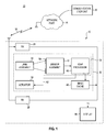
- Figure 1 illustrates a functional block diagram of a communication system having a device that includes an implementation of the present disclosure.
- FIG. 2 illustrates a representation of operation of an extended depth of field (EDOF) image, divided into portions in which pursuant to operation to form an EDOF image.
- EDOF extended depth of field
- Figure 3 illustrates a representation of the relationship between a camera lens translated between different positions pursuant to an implementation of the present disclosure.
- the present disclosure accordingly, advantageously provides an apparatus, and an associated method, by which to record an image of a subject by a camera module, such as the camera module of a mobile station or other portable, wireless device.
- the camera lens is translatable through operation of an actuator.
- the actuator provides actuation forces that provide for the translation of the camera lens.
- the camera is translatable between a range of camera-lens positions. The position of the camera lens into different camera-lens position changes the location at which a subject is focused. The camera-lens position at which the subject is focused is dependent upon the characteristics of the camera lens, amongst other criteria.
- an EDOF, Extended Depth of Field, element is utilized to sense incident light energy and to form an EDOF image therefrom.
- the EDOF element includes pixels that sense colors of the light energy incident thereon.
- EDOF processing is performed to create an EDOF image that forms the recorded image.
- the EDOF processing results in an image that is of improved depth of field characteristics relative to conventional image formation.
- the EDOF processing compensates for the limited depth of field inherent of low F-stop lenses.
- a wireless device regularly also includes additional functionality in addition to functionalities conventionally provided for telephonic and data communications.
- a function sometimes provided at a wireless device is a camera functionality.
- a camera functionality provides for the recordation of a subject image, either a still image or video sequence of images.
- the camera functionality is embodied, at least in part, by a camera module, typically housed at the housing of the wireless device. Images recorded by the camera functionality are displayable at, e.g., at a display element of the wireless device or provided to another location to be stored, displayed, or viewed elsewhere.
- a representation, shown generally at 74 illustrates the relationship between the position of the lens assembly 36 and the sensor assembly 42, which form portions of the apparatus 32, shown in Figure 1 .
- the lens assembly, or one or more lenses thereof, is translatable, here in the direction indicated by the arrow 76 (and in a direction opposite to that of the arrow 76).
- the translation is caused by application of translation forces provided by the actuator (shown in Figure 1 ).
- the representation 74 illustrates the lens assembly 36 and the lens assembly, subsequent to translation, indicated by 36'.
Landscapes
- Physics & Mathematics (AREA)
- Engineering & Computer Science (AREA)
- Multimedia (AREA)
- Signal Processing (AREA)
- General Physics & Mathematics (AREA)
- Optics & Photonics (AREA)
- Computing Systems (AREA)
- Theoretical Computer Science (AREA)
- Studio Devices (AREA)
- Exposure Control For Cameras (AREA)
Abstract
Description
- The present application claims priority to
U.S. Provisional Application serial no. 61/418,494 filed on December 1, 2010 - The present disclosure relates generally to a manner by which to record an image of a subject by a camera module, such as the camera module of a portable mobile station or other wireless device. More particularly, the present disclosure relates to an apparatus, and an associated method, by which to record the image of the subject at an extended depth of field element, using extended depth of field image-portion selection, focused by a camera lens translatable into a focus position.
- A translatable camera lens of low F-stop, which permits, improved performance in low-light conditions, is used together with extended-depth-of-field image formation, which improves the depth of field characteristics of the resultant, recorded image relative to conventional digital-camera, recording elements.
- Recent years have been witness to many changes permitted as a result of technological advancements. Many new services are, for example, now available and used by many, made possible due to such technological advancements.
- For instance, communication services, together with the network infrastructures and devices through which such services are provided, are now available and regularly used by many. Cellular, and other analogous, wireless communication systems are exemplary of the new communication services that have been developed and deployed, which take advantage of technological advancements. Successive generations of cellular communication systems have been deployed, each providing improved communication services and capabilities. New-generation, cellular communication system, for instance, provide significant data communication capabilities.
- Typically, communications are carried out in a cellular, or cellular-like, communication system through use of a portable wireless device that includes transceiver circuitry. A portable wireless device is typically of compact dimensions to permit a user of the device to hand-carry the device. Users of such wireless devices, as a result, regularly hand-carry a wireless device and thereby have the wireless device available to use to communicate there through whenever the user elects, as long as the user is positioned within the coverage area of a cellular, or other analogous, communication system.
- Some wireless devices provide additional functionalities, in addition to the functionalities provided by the transceiver circuitry. And, such a wireless device forms a multi-functional device that has multiple functionalities.
- A wireless device sometimes, for instance, includes camera functionality. The camera functionality, typically implemented through use of a camera module, provides for the recordation of an image. Once recorded, the data forming the image is subsequently displayable at an image display element, either an image display element of the wireless device, or a display element positioned elsewhere. Existing wireless devices are capable, for instance, of transmitting the data representative of the recorded image by way of the cellular communication system to a remote location for storage or display thereat. The camera functionalities of some wireless devices, in addition to being capable of recording still images also are capable of recording video sequences. And, wireless devices having such capability are also typically capable of transmitting the recorded video sequences to remote locations by way of the cellular communication system.
- Camera modules of portable wireless devices are usually dimensionally constrained. That is to say, the physical dimensions permitted of the camera module are limited due to the need to minimize the physical dimensions of the portable wireless device. And, due to this constraint, the capabilities of the camera functionality are sometimes also limited.
- For instance, the size of a sensor that senses light energy during the image recordation procedure is limited due to this constraint. The sensor includes pixels that sense the receive light energy of different colors, and the limitation of the size of the sensor limits the number pixels that are available to sense the light energy. This limitation is particularly problematical in low-light conditions as there is a lesser amount of light energy incident at the available pixels, and the resultant, recorded image is of reduced quality.
- The size constraints imposed upon camera modules also limits the size permitted of a camera lens. And, due to this limitation, the use of a low F-stop camera lens, for a given focal-length lens, is limited.
- Therefore, existing camera modules that are size-constrained, such as camera modules used at portable wireless devices, suffer from various deficiencies that limit the quality of recorded images that can be obtained.
- It is in light of this background information related to devices having camera functionality that the significant improvements of the present disclosure have evolved.
-
Figure 1 illustrates a functional block diagram of a communication system having a device that includes an implementation of the present disclosure. -
Figure 2 illustrates a representation of operation of an extended depth of field (EDOF) image, divided into portions in which pursuant to operation to form an EDOF image. -
Figure 3 illustrates a representation of the relationship between a camera lens translated between different positions pursuant to an implementation of the present disclosure. -
Figure 4 illustrates a method flow diagram representative of the method of operation of an implementation of the present disclosure. - The present disclosure, accordingly, advantageously provides an apparatus, and an associated method, by which to record an image of a subject by a camera module, such as the camera module of a mobile station or other portable, wireless device.
- Through operation of an implementation of the present disclosure, a manner is provided by which to record the image of a subject at an EDOF (Extended Depth Of Field) element, using EDOF image-portion selection using light focused by a camera lens translatable into a focus position.
- In one aspect of the present disclosure, a translatable camera lens of low F-stop is utilized to provide improved camera performance in low-light conditions. The translatable camera lens is used in conjunction with EDOF image formation, which improves the depth of field characteristics of the resultant, recorded image relative to conventional, digital-camera recording elements.
- In another aspect of the present disclosure, the camera lens is translatable through operation of an actuator. The actuator provides actuation forces that provide for the translation of the camera lens. The camera is translatable between a range of camera-lens positions. The position of the camera lens into different camera-lens position changes the location at which a subject is focused. The camera-lens position at which the subject is focused is dependent upon the characteristics of the camera lens, amongst other criteria.
- In another aspect of the present disclosure, the actuator comprises an electrical actuator implementable in any of various manners. The actuator comprises, for instance, a voice coil motor, a Piezo electric motor, a stepping motor, or other motor capable of generating translation forces to provide for relatively precise, small-step translation movement.
- In another aspect of the present disclosure, the camera lens comprises a low F-stop-lens. The lens comprises, e.g., a lens having an F-stop of less than 2.0. A camera lens that exhibits a low F-stop, i.e., a fast lens, exhibits an aperture of relatively large dimensions, thereby admitting a relatively large amount of light energy, which is particularly advantageous when images are to be recorded in low-light conditions. The low, F-stop lens is positionable into a selected lens position.
- In another aspect of the present disclosure, an EDOF, Extended Depth of Field, element is utilized to sense incident light energy and to form an EDOF image therefrom. The EDOF element includes pixels that sense colors of the light energy incident thereon. And, EDOF processing is performed to create an EDOF image that forms the recorded image. The EDOF processing results in an image that is of improved depth of field characteristics relative to conventional image formation. The EDOF processing compensates for the limited depth of field inherent of low F-stop lenses.
- In another aspect of the present disclosure, the sensors of the EDOF element include clusters of red, green, blue (RGB) pixels. The red, green, and blue color regions are focused differently. Recordations are made of images formed by the different pixel colors. And, the EDOF processing includes comparing corresponding portions of the separate images and selecting, for each portion, an image portion of one of the recorded images that exhibits the best quality. And, the non-selected portions are used to supply coloration rather than detail to the selected image portion. The image portions are, e.g., of 10 by 10 pixel squares. By selection of the image portion from amongst the multiple images, the portions exhibiting the best depth of field characteristics for that portion are selected, resulting in an image of an improved depth of field.
- By utilizing both an extend depth of field element and a translatable camera lens, improved camera performance in low-light conditions is provided.
- In these and other aspects, therefore, an apparatus, and an associated method, is provided for a camera module of an electronic device. An actuator is configured to provide camera-lens translation through a range of camera-lens positions. An extended depth of field element is configured to record an extended depth of field image of a sensed image, subsequent to camera-lens positioning of the actuator at a selected camera-lens position.
- Turning first, therefore, to
Figure 1 , a communication system, shown generally at 10, provides for radio communications with communication devices, here wireless devices of which thewireless device 12 is representative. - In the exemplary implementation, the communication system comprises a multi-user, wireless communication system. While a
single wireless device 12 is illustrated inFigure 1 , in an actual implementation, typically, a large number of wireless devices are concurrently operable to perform communication services. Thecommunication system 10 is representative, for instance, of a cellular communication system that operates in general conformity with a cellular communication system operating standard. More generally, thecommunication system 10 is representative of any of various communication systems, both radio and fixed, in which information is communicated with communication devices. Additionally, the functionality that shall be described below with respect to thewireless device 12 is alternately implementable at a standalone device, i.e., a device that is not used to communicate by way of a communication system. - The
communication system 10, here implemented as a wireless communication system, includes anetwork part 16 having a network infrastructure including fixed radio transceivers capable of communicating with thewireless device 12 by way of radio channels defined upon aradio air interface 18. Acommunication endpoint 22 is connected to thenetwork part 16. The communication endpoint is representative of any communication device placeable in communication connectivity with thenetwork part 16 and, in turn, by way of radio channels on the radio air interface. That is to say, information originated at thewireless device 12 is routable to thecommunication endpoint 22. And, information originated at thecommunication endpoint 22 is routable to thewireless device 12. - The wireless device includes transceiver circuitry, here represented by a receive part (Rx) 26 and a transmit part (Tx) 28. The transceiver circuitry transceives communication signals with corresponding circuitry of the
network part 16. - As noted previously, a wireless device regularly also includes additional functionality in addition to functionalities conventionally provided for telephonic and data communications. A function sometimes provided at a wireless device is a camera functionality. A camera functionality provides for the recordation of a subject image, either a still image or video sequence of images. When forming part of a portable wireless device, dimensional constraints necessitated to maintain the portability of the wireless device are also imposed upon the camera functionality. The camera functionality is embodied, at least in part, by a camera module, typically housed at the housing of the wireless device. Images recorded by the camera functionality are displayable at, e.g., at a display element of the wireless device or provided to another location to be stored, displayed, or viewed elsewhere.
- The dimensional constraints imposed upon the camera module impose limitations on the characteristics of the elements of the camera module. For instance, the camera lens of a lens assembly of the camera module typically is a fixed lens configuration. And, the F-stop of the camera lens is typically relatively large as the maximum aperture of the lens is required to be relatively small. Due to the large F-stop of a conventional lens of such a camera module, the camera module does not provide for good quality image recording in low-light conditions.
- The
wireless device 12 includes acamera module 32 of an implementation of the present disclosure. While thecamera module 32 is of physical dimensions corresponding to the physical dimensions of a conventional camera module, the functionality of thecamera module 32 provides for improved image quality in low-light conditions while permitting construction of the camera module with looser tolerance, viz., of lessened requirements of manufacturing and assembly precision. - The
camera module 32 is functionally represented, implementable in any desired manner including, for instance, hardware elements, firmware elements, algorithms executable by a processor, and combinations thereof. Themodule 32 is here shown to include alens assembly 36, anactuator 38, asensor assembly 42, and EDOF (Extended Depth of Field)processor 46, and animage cache 48. In one implementation, the functionality of thesensor assembly 42 and theEDOF processor 46 are formed at a singlephysical device 50. While the exemplary implementation shown inFigure 1 illustrates the camera module to be a discrete module, in alternate implementations, the functionality of various elements of the camera module are embodied at portions of the wireless device circuitry. And, in other implementations in which the camera module forms part of a standalone device or part of another device, the elements of the camera module are embodied at, or form parts of, the standalone or other device. - The
lens assembly 36 includes one or more camera lenses configured to exhibit a low F-stop, such as an F-stop of less than 2.0. In an exemplary implementation, thecamera assembly 36 comprises two-five lens element stacks, i.e., a lens assembly having two-five camera lenses that are positioned in a manner together to define a camera lens of low F-stop. Conventionally, the lens assembly, particularly of a low F-stop configuration, must be precisely positioned in terms of at least decenter, and tilt as well as relative positioning between the lenses of the assembly. In an implementation of the present disclosure, the precision required in the positioning of the lenses is reduced and tolerances are increased to facilitate manufacture of the lens assembly. - One or more of the lenses of the lens assembly, or the entire lens assembly is translatable to reposition lens. The translation of the lens assembly, or lens thereof, is caused by application of translation forces provided by the
actuator 38. Theactuator 38, in the exemplary implementation, comprises an electric motor, such as a Piezo electric motor, a voice coil motor, a stepping motor, or any of various other motor-type capable of generating translation forces to permit relatively precise positioning of the affected lens or lenses. - The lens assembly is positioned in a manner such that light passing through the lens assembly representative of a subject is detectable by
sensors 54 of thesensor assembly 42. Thesensor 54 are arranged in groups of red, green, and blue (RGB) pixels. The different-colored pixels have different focus characteristics from one another. The sensor assembly generates electrical representations of the sensed light energy. Indications are provided to theEDOF processor 46. In one implementation, the sensor assembly and the EDOF processor are embodied in a common, physical element. The EDOF processor, howsoever implemented, processes the sensed indications and forms an EDOF image therefrom. The processing performed by the processor permits formation of a resultant image that has an extended depth of field. That is to say, the portion of the resultant image that is in-focus, when viewed, is greater than an image formed absent EDOF processing. The EDOF processing is particularly advantageous when the lens assembly, as in the exemplary implementation, exhibits a low F-stop. Low F-stop lenses inherently provide for images that are of small depths of field. Use of the EDOF processing to extend the depth of field of the sensed image improves the picture quality of the resultant image. - Once formed, the resultant image is stored at the
image cache 48, available, e.g., for subsequent display at adisplay 58 of the device or to be transmitted by the transmitpart 28 elsewhere, such as to thecommunication endpoint 22 for further use or display thereat. - In one implementation, the
EDOF processor 46 further provides actuation instructions, here represented by way of theline 62, to theactuator 38. Actuation instructions include instructions to cause the actuator to generate translation forces to translate the lens assembly, or camera lens thereof. Such actuation changes the distance between the lens assembly and thepixels 54 of the sensor assembly. Thereby, in the event that the processing performed by the processor indicates that a better lens position would form improved images, such as images with greater depths of field, actuation is caused to be performed to reposition the lens by translating the lens assembly in an appropriate translation direction. - Turning next to
Figure 2 , a representation, shown generally at 74, illustrates the relationship between the position of thelens assembly 36 and thesensor assembly 42, which form portions of theapparatus 32, shown inFigure 1 . The lens assembly, or one or more lenses thereof, is translatable, here in the direction indicated by the arrow 76 (and in a direction opposite to that of the arrow 76). The translation is caused by application of translation forces provided by the actuator (shown inFigure 1 ). Therepresentation 74 illustrates thelens assembly 36 and the lens assembly, subsequent to translation, indicated by 36'. - A subject 78, whose image is to be recorded, is located in sight of the camera lens. That is to say, the device at which the lens assembly is positioned is positioned to sight the lens in the direction of the subject 78.
- The image presented to the
sensor assembly 42 is dependent upon the position of the lens assembly. When the lens assembly is positioned as indicated by theassembly 36, a first image having outlines indicated by thepaths 82, are presented to the sensor assembly. And, the when the lens assembly is positioned as indicated at 36', the image presented to the pixels of the sensor assembly are indicated by the outline 82'. The image presented to the sensor assembly differs, depending upon the position of the lens assembly. By providing for translation of the lens assembly or a camera lens thereof, variations in lenses due to manufacturing and assembly tolerances are compensated for by translation of the lens. -
Figure 3 illustrates anexemplary image 92, representative of an image recorded during operation of an implementation of the present disclosure. Here, the image is divided into a plurality ofregions 96. In the illustrated implementation, the regions define an array of horizontally and vertically aligned image portions. In operation, the multiple images are obtained, such as a separate image comprised of light sensed by the red, green, and blue pixels of the sensor assembly. The EDOF processing includes comparison of each of the separate images and selection of the image that exhibits the best characteristics. The non-selected portions are used for colorization purposes. The criteria for selection includes, for instance, the image portion of the corresponding, multiple image portions that exhibits the best depth of field. Thereby, the resultant image is of improved image quality, including improved depth of field characteristics. -
Figure 4 illustrates a method flow diagram 102 representative of exemplary operation of an implementation of the present disclosure. Themethod 102 facilitates formation of a camera image at an electronic device. - First, and as indicated by the
block 104, a camera lens is translated into a selected camera lens position of a range of camera lens positions. And, as indicated by theblock 106, an extended-depth-of-field (EDOF) image of a sensed image is recorded. The EDOF image sensed at an EDOF element, is sensed subsequent to translation of the camera lens into the selected camera lens position - Thereby, through use of a camera lens assembly that is translatable into a selected lens position, manufacturing and assembly tolerances of a lens assembly are easier to meet, while providing a low F-stop lens assembly that passes large amounts of light relative to higher F-stop lenses. The depth of field of the resultant, recorded image is improved as the EDOF processing provides for an image of improved depth of field characteristics.
- Presently preferred implementations of the disclosure and many improvements and advantages have been described with a degree of particularity. The description is of preferred examples of implementing the disclosure, and the description of examples is not necessarily intended to limit the scope of the disclosure. The scope of the disclosure is defined by the following claims.
Claims (15)
- An apparatus for a camera module of an electronic device, said apparatus comprising:an actuator configured to provide camera-lens translation through a range of camera-lens positions; andan extended depth of field element configured to record an extended-depth-of field image of a sensed image, subsequent to camera-lens positioning of said actuator at a selected camera-lens position.
- The apparatus of claim 1 further comprising a camera lens having a lens characteristic that defines a focal length, and wherein said actuator is configured to provide camera-lens translation of said camera lens.
- The apparatus of claim 2 wherein the composite image recorded by said EDOF element is dependent, in part, upon positioning of said camera lens by said actuator.
- The apparatus of claim 1 wherein said actuator is configured to provide camera-lens translation through a range of camera-lens positions including a macro-lens position.
- The apparatus of claim 1 wherein said extended depth of field element is configured to record a still, extended-depth-of field image.
- The apparatus of claim 1 wherein said extended depth of field element is configured to record a video sequence of extended -depth-of-field images.
- The apparatus of claim 1 further comprising a camera lens having an F-stop of less than 2.0.
- The apparatus of claim 1 wherein said actuator comprises a voice coil motor.
- The apparatus of claim 1 wherein said actuator comprises a Piezo electric motor.
- The apparatus of claim 1 wherein said actuator comprises a stepping motor.
- The apparatus of claim 1 further comprising a liquid-crystal camera lens and wherein said actuator comprises an electromagnetic field voltage generator.
- A method for facilitating formation of a camera image at an electronic device, said method comprising:translating a camera lens into a selected camera lens position of a range of camera lens positions; andrecording an extended-depth-of-field image of a sensed image at an extended depth of field element, subsequent to translation of the camera lens into the selected camera lens position.
- The method of claim 12 wherein said translating comprises translating the camera lens into a selected camera lens position of a range of camera lens positions including a macro lens position.
- The method of claim 12 wherein said recording comprises recording a still, extended-depth-of-field image.
- The method of claim 13 wherein said recording comprises recording a video sequence of extended-depth-of-field images.
Priority Applications (2)
| Application Number | Priority Date | Filing Date | Title |
|---|---|---|---|
| CA2758119A CA2758119C (en) | 2010-12-01 | 2011-11-08 | Apparatus, and associated method, for a camera module of electronic device |
| CN201110354796.7A CN102486565B (en) | 2010-12-01 | 2011-11-10 | For device and the method that is associated of the camera model of electronic equipment |
Applications Claiming Priority (1)
| Application Number | Priority Date | Filing Date | Title |
|---|---|---|---|
| US41849410P | 2010-12-01 | 2010-12-01 |
Publications (2)
| Publication Number | Publication Date |
|---|---|
| EP2461198A2 true EP2461198A2 (en) | 2012-06-06 |
| EP2461198A3 EP2461198A3 (en) | 2017-03-08 |
Family
ID=45524227
Family Applications (1)
| Application Number | Title | Priority Date | Filing Date |
|---|---|---|---|
| EP11173042.0A Ceased EP2461198A3 (en) | 2010-12-01 | 2011-07-07 | Apparatus, and associated method, for a camera module of electronic device |
Country Status (4)
| Country | Link |
|---|---|
| US (1) | US8947584B2 (en) |
| EP (1) | EP2461198A3 (en) |
| CN (1) | CN102486565B (en) |
| CA (1) | CA2758119C (en) |
Families Citing this family (2)
| Publication number | Priority date | Publication date | Assignee | Title |
|---|---|---|---|---|
| US10706569B2 (en) * | 2016-06-08 | 2020-07-07 | Amazon Technologies, Inc. | Selectively paired imaging elements for stereo images |
| CN109839786B (en) * | 2017-11-29 | 2022-11-11 | 扬明光学股份有限公司 | Lens and method for manufacturing same |
Family Cites Families (45)
| Publication number | Priority date | Publication date | Assignee | Title |
|---|---|---|---|---|
| US6611289B1 (en) | 1999-01-15 | 2003-08-26 | Yanbin Yu | Digital cameras using multiple sensors with multiple lenses |
| US6556349B2 (en) | 2000-12-27 | 2003-04-29 | Honeywell International Inc. | Variable focal length micro lens array field curvature corrector |
| US6956612B2 (en) * | 2001-07-31 | 2005-10-18 | Hewlett-Packard Development Company, L.P. | User selectable focus regions in an image capturing device |
| US7084910B2 (en) * | 2002-02-08 | 2006-08-01 | Hewlett-Packard Development Company, L.P. | System and method for using multiple images in a digital image capture device |
| JP3986988B2 (en) * | 2002-09-27 | 2007-10-03 | 富士フイルム株式会社 | Automatic focusing method and apparatus |
| US20040100573A1 (en) * | 2002-11-21 | 2004-05-27 | Osamu Nonaka | Focusing apparatus and camera including the same |
| US7633537B2 (en) | 2002-12-18 | 2009-12-15 | Nikon Corporation | Color image sensor, color filter array and color imaging device |
| KR100919987B1 (en) * | 2003-04-22 | 2009-10-05 | 삼성테크윈 주식회사 | Small digital zoom camera and mobile phone equipped with it |
| US8264576B2 (en) | 2007-03-05 | 2012-09-11 | DigitalOptics Corporation Europe Limited | RGBW sensor array |
| FI20031816A0 (en) | 2003-12-11 | 2003-12-11 | Nokia Corp | Method and device for creating an image |
| EP1812968B1 (en) | 2004-08-25 | 2019-01-16 | Callahan Cellular L.L.C. | Apparatus for multiple camera devices and method of operating same |
| JP2006086952A (en) * | 2004-09-17 | 2006-03-30 | Casio Comput Co Ltd | Digital camera and program |
| US7653298B2 (en) * | 2005-03-03 | 2010-01-26 | Fujifilm Corporation | Image capturing apparatus, image capturing method, image capturing program, image recording output system and image recording output method |
| US20070019883A1 (en) * | 2005-07-19 | 2007-01-25 | Wong Earl Q | Method for creating a depth map for auto focus using an all-in-focus picture and two-dimensional scale space matching |
| US7566853B2 (en) | 2005-08-12 | 2009-07-28 | Tessera, Inc. | Image sensor employing a plurality of photodetector arrays and/or rear-illuminated architecture |
| US7909256B2 (en) * | 2005-12-31 | 2011-03-22 | Motorola Mobility, Inc. | Method and system for automatically focusing a camera |
| US20070189750A1 (en) * | 2006-02-16 | 2007-08-16 | Sony Corporation | Method of and apparatus for simultaneously capturing and generating multiple blurred images |
| TW200742923A (en) * | 2006-05-11 | 2007-11-16 | Asia Optical Co Inc | Method of auto focus |
| US7703711B2 (en) | 2006-05-17 | 2010-04-27 | Smith Johnice C | Combination shredder-storage unit |
| US7711259B2 (en) * | 2006-07-14 | 2010-05-04 | Aptina Imaging Corporation | Method and apparatus for increasing depth of field for an imager |
| US20080080028A1 (en) | 2006-10-02 | 2008-04-03 | Micron Technology, Inc. | Imaging method, apparatus and system having extended depth of field |
| US7634187B2 (en) * | 2007-01-04 | 2009-12-15 | Qualcomm Incorporated | Dynamic auto-focus window selection that compensates for hand jitter |
| US7646977B2 (en) * | 2007-01-17 | 2010-01-12 | Gateway, Inc. | Depth of field bracketing |
| US7812869B2 (en) | 2007-05-11 | 2010-10-12 | Aptina Imaging Corporation | Configurable pixel array system and method |
| KR100976284B1 (en) | 2007-06-07 | 2010-08-16 | 가부시끼가이샤 도시바 | Imaging device |
| US20090009584A1 (en) | 2007-07-03 | 2009-01-08 | Azurewave Technologies, Inc. | Wireless image signal transmission device |
| US20090015681A1 (en) * | 2007-07-12 | 2009-01-15 | Sony Ericsson Mobile Communications Ab | Multipoint autofocus for adjusting depth of field |
| US8059163B2 (en) * | 2007-08-28 | 2011-11-15 | Sony Computer Entertainment Inc. | Digital photography using electronic image analysis to identify faces of faces of known subjects in predetermined position |
| US8390729B2 (en) * | 2007-09-05 | 2013-03-05 | International Business Machines Corporation | Method and apparatus for providing a video image having multiple focal lengths |
| US8072503B2 (en) * | 2007-10-23 | 2011-12-06 | At&T Intellectual Property I, L.P. | Methods, apparatuses, systems, and computer program products for real-time high dynamic range imaging |
| US20090169122A1 (en) * | 2007-12-27 | 2009-07-02 | Motorola, Inc. | Method and apparatus for focusing on objects at different distances for one image |
| US8325268B2 (en) * | 2007-12-28 | 2012-12-04 | Sanyo Electric Co., Ltd. | Image processing apparatus and photographing apparatus |
| JP5039570B2 (en) * | 2008-01-09 | 2012-10-03 | キヤノン株式会社 | Display device, video display system, and display method |
| US20090196489A1 (en) * | 2008-01-30 | 2009-08-06 | Le Tuan D | High resolution edge inspection |
| JP5005570B2 (en) * | 2008-02-04 | 2012-08-22 | 株式会社リコー | Image processing apparatus and program |
| JP5381060B2 (en) * | 2008-02-05 | 2014-01-08 | 株式会社リコー | Imaging apparatus and image processing method thereof |
| US8436909B2 (en) | 2008-10-21 | 2013-05-07 | Stmicroelectronics S.R.L. | Compound camera sensor and related method of processing digital images |
| US8610815B2 (en) | 2009-01-12 | 2013-12-17 | Aptina Imaging Corporation | Imaging device having microlens array adhered to wafer-level lens |
| CN102356630B (en) * | 2009-03-19 | 2016-01-27 | 数字光学公司 | Dual sensor camera |
| ATE551841T1 (en) | 2009-04-22 | 2012-04-15 | Raytrix Gmbh | DIGITAL IMAGING METHOD FOR SYNTHESIZING AN IMAGE USING DATA RECORDED BY A PLENOPTIC CAMERA |
| US8330840B2 (en) | 2009-08-06 | 2012-12-11 | Aptina Imaging Corporation | Image sensor with multilayer interference filters |
| US8400555B1 (en) | 2009-12-01 | 2013-03-19 | Adobe Systems Incorporated | Focused plenoptic camera employing microlenses with different focal lengths |
| US20120019703A1 (en) * | 2010-07-22 | 2012-01-26 | Thorn Karl Ola | Camera system and method of displaying photos |
| JP5657343B2 (en) * | 2010-10-28 | 2015-01-21 | 株式会社ザクティ | Electronics |
| US9197798B2 (en) | 2011-03-25 | 2015-11-24 | Adobe Systems Incorporated | Thin plenoptic cameras using microspheres |
-
2011
- 2011-07-07 US US13/178,337 patent/US8947584B2/en active Active
- 2011-07-07 EP EP11173042.0A patent/EP2461198A3/en not_active Ceased
- 2011-11-08 CA CA2758119A patent/CA2758119C/en active Active
- 2011-11-10 CN CN201110354796.7A patent/CN102486565B/en active Active
Also Published As
| Publication number | Publication date |
|---|---|
| US8947584B2 (en) | 2015-02-03 |
| CN102486565B (en) | 2015-07-29 |
| CA2758119C (en) | 2017-07-11 |
| EP2461198A3 (en) | 2017-03-08 |
| CN102486565A (en) | 2012-06-06 |
| US20120140108A1 (en) | 2012-06-07 |
| CA2758119A1 (en) | 2012-06-01 |
Similar Documents
| Publication | Publication Date | Title |
|---|---|---|
| US9723292B2 (en) | Imaging device | |
| US7206136B2 (en) | Digital camera using multiple lenses and image sensors to provide an extended zoom range | |
| EP3136707A1 (en) | Image shooting terminal and image shooting method | |
| US7256944B2 (en) | Compact image capture assembly using multiple lenses and image sensors to provide an extended zoom range | |
| US7236306B2 (en) | Digital camera using an express zooming mode to provide expedited operation over an extended zoom range | |
| KR101785458B1 (en) | Camera module and mobile terminal having the same | |
| EP3017338B1 (en) | Thin dual-aperture zoom digital camera | |
| US20060187338A1 (en) | Camera phone using multiple lenses and image sensors to provide an extended zoom range | |
| US20060187322A1 (en) | Digital camera using multiple fixed focal length lenses and multiple image sensors to provide an extended zoom range | |
| JP5542249B2 (en) | Image pickup device, image pickup apparatus using the same, and image pickup method | |
| WO2015198691A1 (en) | Imaging device | |
| WO2014083914A1 (en) | Image capture device and focus control method | |
| KR20070041341A (en) | Imaging device | |
| KR20220070277A (en) | Camera module and terminal device | |
| JP5542248B2 (en) | Imaging device and imaging apparatus | |
| US8947584B2 (en) | Apparatus, and associated method, for a camera module of electronic device | |
| CN112468686B (en) | Camera module and mobile terminal having the same | |
| EP3789823B1 (en) | Camera module and mobile terminal having the camera module | |
| HK1170026A (en) | Apparatus, and associated method, for a camera module of electronic device | |
| KR100562720B1 (en) | Compact camera device for communication device and communication device having same | |
| CN107071256A (en) | Camera components and electronics | |
| EP4111248B1 (en) | Lens positioning module | |
| CN112468683B (en) | Camera module and mobile terminal having the same | |
| CN103108191A (en) | Apparatus and associated method for forming color camera image | |
| CN216086823U (en) | Imaging module and image device |
Legal Events
| Date | Code | Title | Description |
|---|---|---|---|
| PUAI | Public reference made under article 153(3) epc to a published international application that has entered the european phase |
Free format text: ORIGINAL CODE: 0009012 |
|
| 17P | Request for examination filed |
Effective date: 20110707 |
|
| AK | Designated contracting states |
Kind code of ref document: A2 Designated state(s): AL AT BE BG CH CY CZ DE DK EE ES FI FR GB GR HR HU IE IS IT LI LT LU LV MC MK MT NL NO PL PT RO RS SE SI SK SM TR |
|
| AX | Request for extension of the european patent |
Extension state: BA ME |
|
| REG | Reference to a national code |
Ref country code: HK Ref legal event code: DE Ref document number: 1170026 Country of ref document: HK |
|
| RAP1 | Party data changed (applicant data changed or rights of an application transferred) |
Owner name: BLACKBERRY LIMITED |
|
| RAP1 | Party data changed (applicant data changed or rights of an application transferred) |
Owner name: BLACKBERRY LIMITED |
|
| PUAL | Search report despatched |
Free format text: ORIGINAL CODE: 0009013 |
|
| RIC1 | Information provided on ipc code assigned before grant |
Ipc: G02B 7/08 20060101ALI20170125BHEP Ipc: G02B 27/00 20060101AFI20170125BHEP Ipc: H04N 5/335 20110101ALN20170125BHEP Ipc: G02B 13/00 20060101ALI20170125BHEP |
|
| AK | Designated contracting states |
Kind code of ref document: A3 Designated state(s): AL AT BE BG CH CY CZ DE DK EE ES FI FR GB GR HR HU IE IS IT LI LT LU LV MC MK MT NL NO PL PT RO RS SE SI SK SM TR |
|
| AX | Request for extension of the european patent |
Extension state: BA ME |
|
| RIC1 | Information provided on ipc code assigned before grant |
Ipc: G02B 27/00 20060101AFI20170127BHEP Ipc: H04N 5/335 20110101ALN20170127BHEP Ipc: G02B 7/08 20060101ALI20170127BHEP Ipc: G02B 13/00 20060101ALI20170127BHEP |
|
| 17Q | First examination report despatched |
Effective date: 20171215 |
|
| STAA | Information on the status of an ep patent application or granted ep patent |
Free format text: STATUS: THE APPLICATION HAS BEEN REFUSED |
|
| 18R | Application refused |
Effective date: 20181214 |
|
| REG | Reference to a national code |
Ref country code: HK Ref legal event code: WD Ref document number: 1170026 Country of ref document: HK |