EP2460983A1 - Steam-driven power plant - Google Patents
Steam-driven power plant Download PDFInfo
- Publication number
- EP2460983A1 EP2460983A1 EP11190666A EP11190666A EP2460983A1 EP 2460983 A1 EP2460983 A1 EP 2460983A1 EP 11190666 A EP11190666 A EP 11190666A EP 11190666 A EP11190666 A EP 11190666A EP 2460983 A1 EP2460983 A1 EP 2460983A1
- Authority
- EP
- European Patent Office
- Prior art keywords
- steam
- conduit
- low pressure
- power plant
- intermediate pressure
- Prior art date
- Legal status (The legal status is an assumption and is not a legal conclusion. Google has not performed a legal analysis and makes no representation as to the accuracy of the status listed.)
- Granted
Links
Images


Classifications
-
- F—MECHANICAL ENGINEERING; LIGHTING; HEATING; WEAPONS; BLASTING
- F01—MACHINES OR ENGINES IN GENERAL; ENGINE PLANTS IN GENERAL; STEAM ENGINES
- F01K—STEAM ENGINE PLANTS; STEAM ACCUMULATORS; ENGINE PLANTS NOT OTHERWISE PROVIDED FOR; ENGINES USING SPECIAL WORKING FLUIDS OR CYCLES
- F01K23/00—Plants characterised by more than one engine delivering power external to the plant, the engines being driven by different fluids
- F01K23/02—Plants characterised by more than one engine delivering power external to the plant, the engines being driven by different fluids the engine cycles being thermally coupled
- F01K23/06—Plants characterised by more than one engine delivering power external to the plant, the engines being driven by different fluids the engine cycles being thermally coupled combustion heat from one cycle heating the fluid in another cycle
- F01K23/10—Plants characterised by more than one engine delivering power external to the plant, the engines being driven by different fluids the engine cycles being thermally coupled combustion heat from one cycle heating the fluid in another cycle with exhaust fluid of one cycle heating the fluid in another cycle
-
- F—MECHANICAL ENGINEERING; LIGHTING; HEATING; WEAPONS; BLASTING
- F01—MACHINES OR ENGINES IN GENERAL; ENGINE PLANTS IN GENERAL; STEAM ENGINES
- F01K—STEAM ENGINE PLANTS; STEAM ACCUMULATORS; ENGINE PLANTS NOT OTHERWISE PROVIDED FOR; ENGINES USING SPECIAL WORKING FLUIDS OR CYCLES
- F01K7/00—Steam engine plants characterised by the use of specific types of engine; Plants or engines characterised by their use of special steam systems, cycles or processes; Control means specially adapted for such systems, cycles or processes; Use of withdrawn or exhaust steam for feed-water heating
- F01K7/16—Steam engine plants characterised by the use of specific types of engine; Plants or engines characterised by their use of special steam systems, cycles or processes; Control means specially adapted for such systems, cycles or processes; Use of withdrawn or exhaust steam for feed-water heating the engines being only of turbine type
- F01K7/18—Steam engine plants characterised by the use of specific types of engine; Plants or engines characterised by their use of special steam systems, cycles or processes; Control means specially adapted for such systems, cycles or processes; Use of withdrawn or exhaust steam for feed-water heating the engines being only of turbine type the turbine being of multiple-inlet-pressure type
- F01K7/20—Control means specially adapted therefor
-
- Y—GENERAL TAGGING OF NEW TECHNOLOGICAL DEVELOPMENTS; GENERAL TAGGING OF CROSS-SECTIONAL TECHNOLOGIES SPANNING OVER SEVERAL SECTIONS OF THE IPC; TECHNICAL SUBJECTS COVERED BY FORMER USPC CROSS-REFERENCE ART COLLECTIONS [XRACs] AND DIGESTS
- Y02—TECHNOLOGIES OR APPLICATIONS FOR MITIGATION OR ADAPTATION AGAINST CLIMATE CHANGE
- Y02E—REDUCTION OF GREENHOUSE GAS [GHG] EMISSIONS, RELATED TO ENERGY GENERATION, TRANSMISSION OR DISTRIBUTION
- Y02E20/00—Combustion technologies with mitigation potential
- Y02E20/16—Combined cycle power plant [CCPP], or combined cycle gas turbine [CCGT]
Definitions
- the subject matter disclosed herein relates to steam-driven power plants. More specifically, the subject disclosure relates to control of steam admission into a steam turbine of a combined cycle power plant.
- hot exhaust gas from a gas turbine is introduced to a heat recovery steam generator (HRSG), to convert water to steam for admission into a steam turbine.
- the steam turbine includes a high pressure (HP) turbine section, an intermediate pressure (IP) turbine section and a low pressure (LP) turbine section. Steam is admitted into these turbine sections through admission pipes via one or more admission valves at the turbine sections.
- a minimum operating pressure of the HRSG known as a floor pressure, is determined based on admission pipe size and desired HRSG cost considerations.
- LP admission floor pressure in the HRSG is typically about 5% below LP pressure during full power operation.
- the LP floor pressure is lower than pressure in the LP section.
- the LP section pressure lowers proportionally from the LP section pressure at full load.
- the HSRG is still providing pressure to the LP admission valve at the LP floor pressure, which is greater than the part-power LP section pressure.
- the LP admission valve must throttle the flow through the LP admission valve and LP admission pipe to be equal to or higher than the LP pressure. This throttling of the LP admission valve represents a performance loss to the HRSG and steam turbine system.
- a steam-driven power plant includes a steam source providing steam at a desired pressure and a steam turbine operably connected to the steam source.
- the steam turbine includes a low pressure section and an intermediate pressure section.
- a low pressure admission conduit is configured to convey steam from the steam source to an entrance of the low pressure section and an intermediate pressure admission conduit is configured to convey steam from the steam source to a mid-steampath point of the intermediate pressure section.
- One or more valves are located between the steam source and the steam turbine to control a flow of steam from the steam source through the low pressure admission conduit and/or the intermediate pressure admission conduit.
- a combined cycle power plant includes a power generation apparatus and a heat recovery steam generator operably connected to the power generation apparatus such that heat exhaust from the power generation apparatus is input into the heat recovery steam generator.
- a steam turbine operably connected to the heat recovery steam generator and includes a low pressure section and an intermediate pressure section.
- a low pressure admission conduit is configured to convey steam from the heat recovery steam generator to an entrance of the low pressure section and an intermediate pressure admission conduit configured to convey steam from the heat recovery steam generator to a mid-steampath point of the intermediate pressure section.
- One or more valves are located between the heat recovery steam generator and the steam turbine to control a flow of steam from the heat recovery steam generator through the low pressure admission conduit and/or the intermediate pressure admission conduit.
- a method of admitting steam into a steam turbine includes providing steam at a steam source and conveying the steam through a steam conduit toward the steam turbine.
- the steam is routed through a low pressure admission conduit to an entrance of a low pressure section of the steam turbine and/or through an intermediate pressure steam conduit to a mid-steampath point of an intermediate pressure section of the steam turbine, depending on operating conditions of the steam turbine.
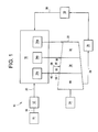
- FIG. 1 Shown in FIG. 1 is a schematic of a combined cycle power plant 10.
- the combined cycle power plant 10 includes a gas turbine 12, or other power generation system such as a nuclear reactor.
- a mixture of fuel and air is combusted in the gas turbine 12 and drives rotation of a gas turbine shaft 14.
- the gas turbine shaft 14 is connected to a first generator 16 such that rotation of the gas turbine shaft 14 drives the first generator 16 thereby producing electrical power.
- Exhaust heat from the gas turbine 12 is introduced to a heat recovery steam generator (HRSG) 18 via stream 20.
- the HRSG 18 utilizes the exhaust heat to produce steam to drive a steam turbine 22.
- the steam turbine 22 is connected to a second generator 24 such that rotation of the steam turbine 22 drives the second generator 24 thereby producing electrical power.
- HRSG heat recovery steam generator
- exhaust steam 26 from the steam turbine 22 is condensed in a condenser 28 and urged to the HRSG 18 via condensate conduit 30.
- a pump 32 is provided to urge the condensate to the HRSG 18.
- the HRSG 18 produces steam in drums 34 corresponding to portions of the steam turbine 22. Steam is produced in a high pressure drum 34a and introduced to the steam turbine 22 at an entrance to a high pressure section 36 of the steam turbine 22. Similarly, steam is produced in an intermediate pressure drum 34b and introduced to the steam turbine 22 at an entrance to an intermediate pressure section 38. Finally, steam is generated in a low pressure drum 34c and introduced to the steam turbine 22. Introduction of the steam to the steam turbine 22 drives rotation of the steam turbine 22 thereby driving the second generator 24 to produce electrical power.
- steam is directed to the steam turbine 22 from the low pressure drum 34c via a steam conduit 40.
- the steam conduit 40 is connected to a low pressure admission valve 42 configured to introduce steam from the low steam conduit 40 at an entrance to a low pressure section 44 of the steam turbine 22 via a low pressure admission conduit 56.
- the steam conduit 40 is further connected to an intermediate pressure mid-steampath valve 46 configured to introduce steam from the steam conduit 40 into the intermediate pressure section 38 at a mid-steampath point 48 via an intermediate pressure admission conduit 58.
- the mid-steampath point 48 is located substantially between an intermediate pressure section entrance 50 and an intermediate pressure section exit 52.
- the low pressure admission valve 42 and the intermediate pressure mid-steampath valve 46 are connected to a controller 54 which opens and closes the low pressure admission valve 42 and the intermediate pressure mid-steampath valve 46 depending on operating conditions of the combined cycle power plant 10.
- the steam is produced in the low pressure drum 34c, which in some embodiments is in the range of about 50-60 psia at full power.
- pressure in the low pressure section 44 is about at or above the floor pressure.
- the controller 54 opens the low pressure admission valve 42 and closes the intermediate pressure mid-steampath valve 46 thus directing steam from the low pressure drum 34c through the low pressure admission conduit 56 and into the steam turbine 22 at an entrance to the low pressure section 44.
- the pressure in the low pressure section 44 is significantly lower than the floor pressure.
- the pressure in the low pressure section 44 may be about 29 psia, compared to a floor pressure of 50-60 psia.
- the low pressure admission valve 42 will need to be throttled to reduce the pressure of the steam introduced to the entrance of the low pressure section 44. Such throttling would result in losses to the system.
- the low pressure admission valve 42 is closed, and the intermediate pressure mid-steampath valve 46 is opened to introduce the steam from the low pressure drum 34c at the mid-steampath point 48 via the intermediate pressure admission conduit 58, where the pressure in the intermediate pressure section 38 is equal to or lower than the floor pressure. Admitting the steam from the low pressure drum 34c at a point upstream of the entrance to the low pressure section 44 allows additional work to be produced from the low pressure drum 34c steam, and prevents losses in the system thereby increasing efficiency of the combined cycle power plant 10.
- more than one intermediate pressure mid-steampath valve 46 may be provided, located at different points along the intermediate pressure section 38.
- the controller selects the appropriate intermediate pressure mid-steampath valve 46 and admission conduit 58 based on the pressure at particular points in the intermediate pressure section 38 under the particular part power condition at which the combined cycle power plant 10 is operating. This allows for matching of the steam pressure to the intermediate pressure section 38 pressure, further reducing system losses.
- the steam turbine 22 includes the high pressure section 36 and low pressure section 44, and the intermediate pressure section is absent.
- the mid-steampath point 48 is located at the high pressure section 36 and steam is admitted from the admission conduit 58 at the mid-steampath point 48 to reduce system losses.
Landscapes
- Engineering & Computer Science (AREA)
- Chemical & Material Sciences (AREA)
- Combustion & Propulsion (AREA)
- Mechanical Engineering (AREA)
- General Engineering & Computer Science (AREA)
- Engine Equipment That Uses Special Cycles (AREA)
- Control Of Turbines (AREA)
Abstract
Description
- The subject matter disclosed herein relates to steam-driven power plants. More specifically, the subject disclosure relates to control of steam admission into a steam turbine of a combined cycle power plant.
- In a typical combined cycle power plant, hot exhaust gas from a gas turbine is introduced to a heat recovery steam generator (HRSG), to convert water to steam for admission into a steam turbine. The steam turbine includes a high pressure (HP) turbine section, an intermediate pressure (IP) turbine section and a low pressure (LP) turbine section. Steam is admitted into these turbine sections through admission pipes via one or more admission valves at the turbine sections. A minimum operating pressure of the HRSG, known as a floor pressure, is determined based on admission pipe size and desired HRSG cost considerations. During operation of the system, it is desired to maintain a pressure in the LP turbine section equal to or below LP admission pipe pressure. LP admission floor pressure in the HRSG is typically about 5% below LP pressure during full power operation. During full power operation, this is not problematic since the LP floor pressure is lower than pressure in the LP section. During part-power operations of the steam turbine, for example, 40% power, the LP section pressure lowers proportionally from the LP section pressure at full load. The HSRG, however, is still providing pressure to the LP admission valve at the LP floor pressure, which is greater than the part-power LP section pressure. In such situations, the LP admission valve must throttle the flow through the LP admission valve and LP admission pipe to be equal to or higher than the LP pressure. This throttling of the LP admission valve represents a performance loss to the HRSG and steam turbine system.
- According to one aspect of the invention, a steam-driven power plant includes a steam source providing steam at a desired pressure and a steam turbine operably connected to the steam source. The steam turbine includes a low pressure section and an intermediate pressure section. A low pressure admission conduit is configured to convey steam from the steam source to an entrance of the low pressure section and an intermediate pressure admission conduit is configured to convey steam from the steam source to a mid-steampath point of the intermediate pressure section. One or more valves are located between the steam source and the steam turbine to control a flow of steam from the steam source through the low pressure admission conduit and/or the intermediate pressure admission conduit.
- According to another aspect of the invention, a combined cycle power plant includes a power generation apparatus and a heat recovery steam generator operably connected to the power generation apparatus such that heat exhaust from the power generation apparatus is input into the heat recovery steam generator. A steam turbine operably connected to the heat recovery steam generator and includes a low pressure section and an intermediate pressure section. A low pressure admission conduit is configured to convey steam from the heat recovery steam generator to an entrance of the low pressure section and an intermediate pressure admission conduit configured to convey steam from the heat recovery steam generator to a mid-steampath point of the intermediate pressure section. One or more valves are located between the heat recovery steam generator and the steam turbine to control a flow of steam from the heat recovery steam generator through the low pressure admission conduit and/or the intermediate pressure admission conduit.
- According to yet another aspect of the invention, a method of admitting steam into a steam turbine includes providing steam at a steam source and conveying the steam through a steam conduit toward the steam turbine. The steam is routed through a low pressure admission conduit to an entrance of a low pressure section of the steam turbine and/or through an intermediate pressure steam conduit to a mid-steampath point of an intermediate pressure section of the steam turbine, depending on operating conditions of the steam turbine.
- These and other advantages and features will become more apparent from the following description taken in conjunction with the drawings.
- The subject matter, which is regarded as the invention, is particularly pointed out and distinctly claimed in the claims at the conclusion of the specification.
- Embodiments of the invention will now be described, by way of example only, with reference to the accompanying drawings in which:
-
FIG. 1 is a schematic view of an embodiment of a combined cycle power plant; -
FIG. 2 is a partial schematic view of an embodiment of a combined cycle power plant; and -
FIG. 3 is a schematic of another embodiment of a combined cycle power plant. - The detailed description explains embodiments of the invention, together with advantages and features, by way of example with reference to the drawings.
- Shown in
FIG. 1 is a schematic of a combinedcycle power plant 10. The combinedcycle power plant 10 includes agas turbine 12, or other power generation system such as a nuclear reactor. A mixture of fuel and air is combusted in thegas turbine 12 and drives rotation of agas turbine shaft 14. Thegas turbine shaft 14 is connected to afirst generator 16 such that rotation of thegas turbine shaft 14 drives thefirst generator 16 thereby producing electrical power. Exhaust heat from thegas turbine 12 is introduced to a heat recovery steam generator (HRSG) 18 viastream 20. The HRSG 18 utilizes the exhaust heat to produce steam to drive asteam turbine 22. Thesteam turbine 22 is connected to asecond generator 24 such that rotation of thesteam turbine 22 drives thesecond generator 24 thereby producing electrical power. - More specifically,
exhaust steam 26 from thesteam turbine 22 is condensed in acondenser 28 and urged to the HRSG 18 viacondensate conduit 30. In some embodiments, apump 32 is provided to urge the condensate to theHRSG 18. The HRSG 18 produces steam in drums 34 corresponding to portions of thesteam turbine 22. Steam is produced in ahigh pressure drum 34a and introduced to thesteam turbine 22 at an entrance to ahigh pressure section 36 of thesteam turbine 22. Similarly, steam is produced in anintermediate pressure drum 34b and introduced to thesteam turbine 22 at an entrance to anintermediate pressure section 38. Finally, steam is generated in alow pressure drum 34c and introduced to thesteam turbine 22. Introduction of the steam to thesteam turbine 22 drives rotation of thesteam turbine 22 thereby driving thesecond generator 24 to produce electrical power. - Referring now to
FIG. 2 , steam is directed to thesteam turbine 22 from thelow pressure drum 34c via asteam conduit 40. Thesteam conduit 40 is connected to a lowpressure admission valve 42 configured to introduce steam from thelow steam conduit 40 at an entrance to alow pressure section 44 of thesteam turbine 22 via a lowpressure admission conduit 56. Thesteam conduit 40 is further connected to an intermediatepressure mid-steampath valve 46 configured to introduce steam from thesteam conduit 40 into theintermediate pressure section 38 at amid-steampath point 48 via an intermediatepressure admission conduit 58. Themid-steampath point 48 is located substantially between an intermediatepressure section entrance 50 and an intermediatepressure section exit 52. The lowpressure admission valve 42 and the intermediatepressure mid-steampath valve 46 are connected to acontroller 54 which opens and closes the lowpressure admission valve 42 and the intermediatepressure mid-steampath valve 46 depending on operating conditions of the combinedcycle power plant 10. - The steam is produced in the
low pressure drum 34c, which in some embodiments is in the range of about 50-60 psia at full power. When the combinedcycle power plant 10 is operating at or near full power, pressure in thelow pressure section 44 is about at or above the floor pressure. In such operating conditions, thecontroller 54 opens the lowpressure admission valve 42 and closes the intermediatepressure mid-steampath valve 46 thus directing steam from thelow pressure drum 34c through the lowpressure admission conduit 56 and into thesteam turbine 22 at an entrance to thelow pressure section 44. - On the other hand, when the combined
cycle power plant 10 is operating at part power, for example, about 40% power, pressure in thelow pressure section 44 is significantly lower than the floor pressure. For example, at 40% part power, the pressure in thelow pressure section 44 may be about 29 psia, compared to a floor pressure of 50-60 psia. In these operating conditions, if steam is introduced to the entrance of thelow pressure section 44 from thelow pressure drum 34c, the lowpressure admission valve 42 will need to be throttled to reduce the pressure of the steam introduced to the entrance of thelow pressure section 44. Such throttling would result in losses to the system. To avoid the losses and produce additional work from the steam, the lowpressure admission valve 42 is closed, and the intermediatepressure mid-steampath valve 46 is opened to introduce the steam from thelow pressure drum 34c at themid-steampath point 48 via the intermediatepressure admission conduit 58, where the pressure in theintermediate pressure section 38 is equal to or lower than the floor pressure. Admitting the steam from thelow pressure drum 34c at a point upstream of the entrance to thelow pressure section 44 allows additional work to be produced from thelow pressure drum 34c steam, and prevents losses in the system thereby increasing efficiency of the combinedcycle power plant 10. - In some embodiments, more than one intermediate
pressure mid-steampath valve 46 may be provided, located at different points along theintermediate pressure section 38. When the combinedcycle power plant 10 is under part power operating conditions, the controller selects the appropriate intermediatepressure mid-steampath valve 46 andadmission conduit 58 based on the pressure at particular points in theintermediate pressure section 38 under the particular part power condition at which the combinedcycle power plant 10 is operating. This allows for matching of the steam pressure to theintermediate pressure section 38 pressure, further reducing system losses. - In some embodiments, as shown in
FIG. 3 , thesteam turbine 22 includes thehigh pressure section 36 andlow pressure section 44, and the intermediate pressure section is absent. In such embodiments, themid-steampath point 48 is located at thehigh pressure section 36 and steam is admitted from theadmission conduit 58 at themid-steampath point 48 to reduce system losses. - While the invention has been described in detail in connection with only a limited number of embodiments, it should be readily understood that the invention is not limited to such disclosed embodiments. Rather, the invention can be modified to incorporate any number of variations, alterations, substitutions or equivalent arrangements not heretofore described, but which are commensurate with the spirit and scope of the invention. Additionally, while various embodiments of the invention have been described, it is to be understood that aspects of the invention may include only some of the described embodiments. Accordingly, the invention is not to be seen as limited by the foregoing description, but is only limited by the scope of the appended claims.
Claims (14)
- A steam-driven power plant (10) comprising:a steam source providing steam at a desired pressure;a steam turbine (22) operably connected to the steam source including:a low pressure section (44); andan intermediate pressure section (38);a low pressure admission conduit (56) configured to convey steam from the steam source to an entrance of the low pressure section (44);an intermediate pressure admission conduit (58) configured to convey steam from the steam source to a mid-steampath point (48)of the intermediate pressure section (38); andone or more valves disposed between the steam source and the steam turbine (22) to control a flow of steam from the steam source through the low pressure admission conduit (56) and/or the intermediate pressure admission conduit (58).
- The power plant (10) of Claim 1, wherein the one or more valves comprise:a low pressure admission valve (42) disposed at the low pressure admission conduit (56); andan intermediate pressure valve (46) disposed at the intermediate pressure admission conduit (58).
- The power plant (10) of Claim 1 or 2, wherein the one or more valves is a three way valve connected to the low pressure admission conduit (56) and the intermediate pressure admission conduit (58).
- The power plant of any of Claims 1 to 3, further comprising a controller (54) operably connected to the one or more valves (42,46).
- The power plant of Claim 4, wherein the controller (54) is configured to open and/or close the one or more valves (42,46) depending on operating conditions of the power plant.
- The power plant (10) of Claim 1, wherein the steam source is a heat recovery steam generator.
- The power plant of Claim 4, wherein the steam source is a low pressure drum of a heat recovery steam generator (18).
- The power plant of any of claims 1 to 5, wherein the steam source comprises:a power generation apparatus (12); anda heat recovery steam generator (18) operably connected to the power generation apparatus (12) such that heat exhaust from the power generation apparatus (12) is input into the heat recovery steam generator (18).
- The power plant of Claim 8, wherein the power generation apparatus is a gas turbine (12).
- A method of admitting steam into a steam turbine (22) comprising:providing steam at a steam source;conveying the steam through a steam conduit (40) toward the steam turbine (22); androuting the steam from the steam conduit (40) through a low pressure admission conduit (56) to an entrance of a low pressure section (44) of the steam turbine (22) and/or through an intermediate pressure steam conduit (40) to a mid-steampath point (48) of an intermediate pressure section (38) of the steam turbine, depending on operating conditions of the steam turbine.
- The method of Claim 10, further comprising opening and/or closing one or more valves disposed at the steam conduit (40) to direct the steam to the low pressure admission conduit (56) and/or the intermediate pressure conduit (58).
- The method of Claim 10 or 11, wherein the operating conditions are a power operating level of the steam turbine (22).
- The method of any of Claims 1 to 12, wherein steam is directed through the low pressure admission conduit (56) during full power operation of the steam turbine (22).
- The method of any of claims 10 to 12, wherein steam is directed through the intermediate pressure steam conduit during part-power operation of the steam turbine (22).
Applications Claiming Priority (1)
| Application Number | Priority Date | Filing Date | Title |
|---|---|---|---|
| US12/957,526 US8776523B2 (en) | 2010-12-01 | 2010-12-01 | Steam-driven power plant |
Publications (2)
| Publication Number | Publication Date |
|---|---|
| EP2460983A1 true EP2460983A1 (en) | 2012-06-06 |
| EP2460983B1 EP2460983B1 (en) | 2017-11-22 |
Family
ID=45065771
Family Applications (1)
| Application Number | Title | Priority Date | Filing Date |
|---|---|---|---|
| EP11190666.5A Active EP2460983B1 (en) | 2010-12-01 | 2011-11-25 | Steam-driven power plant |
Country Status (4)
| Country | Link |
|---|---|
| US (1) | US8776523B2 (en) |
| EP (1) | EP2460983B1 (en) |
| JP (1) | JP5977504B2 (en) |
| CN (1) | CN102562194B (en) |
Cited By (1)
| Publication number | Priority date | Publication date | Assignee | Title |
|---|---|---|---|---|
| EP2865853A1 (en) * | 2013-10-23 | 2015-04-29 | Mitsubishi Hitachi Power Systems, Ltd. | Combined cycle plant |
Families Citing this family (1)
| Publication number | Priority date | Publication date | Assignee | Title |
|---|---|---|---|---|
| EP2829691A1 (en) * | 2013-07-25 | 2015-01-28 | Siemens Aktiengesellschaft | Method for operating a combined power generation system |
Citations (4)
| Publication number | Priority date | Publication date | Assignee | Title |
|---|---|---|---|---|
| FR1350025A (en) * | 1962-12-10 | 1964-01-24 | Rateau Soc | Advanced nuclear power station, with combined gas turbine allowing the supply of peak energy |
| JPS61218707A (en) * | 1985-03-25 | 1986-09-29 | Fuji Electric Co Ltd | Control system for steam turbine having plural rated points |
| EP2136037A2 (en) * | 2008-06-20 | 2009-12-23 | Siemens Aktiengesellschaft | Method and device for operating a steam powerplant facility with steam turbine and process steam consumer |
| EP2143891A2 (en) * | 2008-07-10 | 2010-01-13 | Ansaldo Energia S.P.A. | A device and method for controlling the pressure of a steam turbine of a combined cycle plant and a bypass system thereof |
Family Cites Families (8)
| Publication number | Priority date | Publication date | Assignee | Title |
|---|---|---|---|---|
| JPH0742843B2 (en) * | 1985-02-25 | 1995-05-15 | 株式会社日立製作所 | Start-up control device for mixed pressure turbine |
| US4976100A (en) * | 1989-06-01 | 1990-12-11 | Westinghouse Electric Corp. | System and method for heat recovery in a combined cycle power plant |
| SE470068B (en) * | 1991-06-20 | 1993-11-01 | Abb Stal Ab | Control system for draining / tapping steam at a turbine |
| DE59710782D1 (en) * | 1997-08-15 | 2003-10-30 | Alstom Switzerland Ltd | Steam generator and operating procedures |
| US6442924B1 (en) | 2000-06-13 | 2002-09-03 | General Electric Company | Optimized steam turbine peaking cycles utilizing steam bypass and related process |
| JP4274846B2 (en) * | 2003-04-30 | 2009-06-10 | 三菱重工業株式会社 | Carbon dioxide recovery method and system |
| US20100242430A1 (en) * | 2009-03-31 | 2010-09-30 | General Electric Company | Combined cycle power plant including a heat recovery steam generator |
| US20100305768A1 (en) * | 2009-06-01 | 2010-12-02 | General Electric Company | Control for improved thermal performance of a steam turbine at partial load |
-
2010
- 2010-12-01 US US12/957,526 patent/US8776523B2/en active Active
-
2011
- 2011-11-25 EP EP11190666.5A patent/EP2460983B1/en active Active
- 2011-11-29 JP JP2011259667A patent/JP5977504B2/en active Active
- 2011-12-01 CN CN201110417575.XA patent/CN102562194B/en active Active
Patent Citations (4)
| Publication number | Priority date | Publication date | Assignee | Title |
|---|---|---|---|---|
| FR1350025A (en) * | 1962-12-10 | 1964-01-24 | Rateau Soc | Advanced nuclear power station, with combined gas turbine allowing the supply of peak energy |
| JPS61218707A (en) * | 1985-03-25 | 1986-09-29 | Fuji Electric Co Ltd | Control system for steam turbine having plural rated points |
| EP2136037A2 (en) * | 2008-06-20 | 2009-12-23 | Siemens Aktiengesellschaft | Method and device for operating a steam powerplant facility with steam turbine and process steam consumer |
| EP2143891A2 (en) * | 2008-07-10 | 2010-01-13 | Ansaldo Energia S.P.A. | A device and method for controlling the pressure of a steam turbine of a combined cycle plant and a bypass system thereof |
Cited By (1)
| Publication number | Priority date | Publication date | Assignee | Title |
|---|---|---|---|---|
| EP2865853A1 (en) * | 2013-10-23 | 2015-04-29 | Mitsubishi Hitachi Power Systems, Ltd. | Combined cycle plant |
Also Published As
| Publication number | Publication date |
|---|---|
| EP2460983B1 (en) | 2017-11-22 |
| US8776523B2 (en) | 2014-07-15 |
| JP5977504B2 (en) | 2016-08-24 |
| JP2012117532A (en) | 2012-06-21 |
| US20120137685A1 (en) | 2012-06-07 |
| CN102562194B (en) | 2015-07-22 |
| CN102562194A (en) | 2012-07-11 |
Similar Documents
| Publication | Publication Date | Title |
|---|---|---|
| CN101846311B (en) | Systems and methods for pre-warming a heat recovery steam generator and associated steam lines | |
| JP5897274B2 (en) | Steam turbine flow control system | |
| US8789371B2 (en) | Power generation apparatus | |
| US7509794B2 (en) | Waste heat steam generator | |
| US20100305768A1 (en) | Control for improved thermal performance of a steam turbine at partial load | |
| US20130118168A1 (en) | Power-generation plant equipment and operating method for the same | |
| CN203809061U (en) | Steam turbine | |
| US20100310356A1 (en) | Clutched steam turbine low pressure sections and methods therefore | |
| JP7167136B2 (en) | Steam turbine plant and its cooling method | |
| US11300011B1 (en) | Gas turbine heat recovery system and method | |
| JP5734117B2 (en) | Combined cycle power plant and operation method thereof | |
| US8776523B2 (en) | Steam-driven power plant | |
| JP2010242673A (en) | Steam turbine system and operation method thereof | |
| JP2013079580A (en) | Method of operating combined power generating facility and combined power generating facility | |
| KR101887971B1 (en) | Low load turndown for combined cycle power plants | |
| JP2006161698A (en) | Steam turbine overload operation apparatus and steam turbine overload operation method | |
| JP5812873B2 (en) | Combined cycle power plant | |
| JP3518252B2 (en) | Closed steam cooled gas turbine combined plant and gas turbine combined plant | |
| JP2023052603A (en) | Steam turbine equipment, combined cycle plant equipped with the same, and modification method for steam turbine equipment | |
| JP2010255527A (en) | Combined cycle power generation system | |
| JP2003343213A (en) | Closed steam-cooled gas turbine combined plant | |
| JP5675516B2 (en) | Combined cycle power plant | |
| JP2026025931A (en) | Combined cycle power plant with steam turbine bypass for simple cycle operation using a heat recovery steam generator and method of use |
Legal Events
| Date | Code | Title | Description |
|---|---|---|---|
| PUAI | Public reference made under article 153(3) epc to a published international application that has entered the european phase |
Free format text: ORIGINAL CODE: 0009012 |
|
| AK | Designated contracting states |
Kind code of ref document: A1 Designated state(s): AL AT BE BG CH CY CZ DE DK EE ES FI FR GB GR HR HU IE IS IT LI LT LU LV MC MK MT NL NO PL PT RO RS SE SI SK SM TR |
|
| AX | Request for extension of the european patent |
Extension state: BA ME |
|
| 17P | Request for examination filed |
Effective date: 20121206 |
|
| 17Q | First examination report despatched |
Effective date: 20151208 |
|
| GRAP | Despatch of communication of intention to grant a patent |
Free format text: ORIGINAL CODE: EPIDOSNIGR1 |
|
| INTG | Intention to grant announced |
Effective date: 20170613 |
|
| GRAS | Grant fee paid |
Free format text: ORIGINAL CODE: EPIDOSNIGR3 |
|
| GRAA | (expected) grant |
Free format text: ORIGINAL CODE: 0009210 |
|
| AK | Designated contracting states |
Kind code of ref document: B1 Designated state(s): AL AT BE BG CH CY CZ DE DK EE ES FI FR GB GR HR HU IE IS IT LI LT LU LV MC MK MT NL NO PL PT RO RS SE SI SK SM TR |
|
| REG | Reference to a national code |
Ref country code: GB Ref legal event code: FG4D |
|
| REG | Reference to a national code |
Ref country code: CH Ref legal event code: EP |
|
| REG | Reference to a national code |
Ref country code: IE Ref legal event code: FG4D |
|
| REG | Reference to a national code |
Ref country code: AT Ref legal event code: REF Ref document number: 948613 Country of ref document: AT Kind code of ref document: T Effective date: 20171215 |
|
| REG | Reference to a national code |
Ref country code: FR Ref legal event code: PLFP Year of fee payment: 7 |
|
| REG | Reference to a national code |
Ref country code: DE Ref legal event code: R096 Ref document number: 602011043529 Country of ref document: DE |
|
| REG | Reference to a national code |
Ref country code: NL Ref legal event code: MP Effective date: 20171122 |
|
| REG | Reference to a national code |
Ref country code: LT Ref legal event code: MG4D |
|
| REG | Reference to a national code |
Ref country code: AT Ref legal event code: MK05 Ref document number: 948613 Country of ref document: AT Kind code of ref document: T Effective date: 20171122 |
|
| PG25 | Lapsed in a contracting state [announced via postgrant information from national office to epo] |
Ref country code: SE Free format text: LAPSE BECAUSE OF FAILURE TO SUBMIT A TRANSLATION OF THE DESCRIPTION OR TO PAY THE FEE WITHIN THE PRESCRIBED TIME-LIMIT Effective date: 20171122 Ref country code: ES Free format text: LAPSE BECAUSE OF FAILURE TO SUBMIT A TRANSLATION OF THE DESCRIPTION OR TO PAY THE FEE WITHIN THE PRESCRIBED TIME-LIMIT Effective date: 20171122 Ref country code: FI Free format text: LAPSE BECAUSE OF FAILURE TO SUBMIT A TRANSLATION OF THE DESCRIPTION OR TO PAY THE FEE WITHIN THE PRESCRIBED TIME-LIMIT Effective date: 20171122 Ref country code: NL Free format text: LAPSE BECAUSE OF FAILURE TO SUBMIT A TRANSLATION OF THE DESCRIPTION OR TO PAY THE FEE WITHIN THE PRESCRIBED TIME-LIMIT Effective date: 20171122 Ref country code: LT Free format text: LAPSE BECAUSE OF FAILURE TO SUBMIT A TRANSLATION OF THE DESCRIPTION OR TO PAY THE FEE WITHIN THE PRESCRIBED TIME-LIMIT Effective date: 20171122 Ref country code: NO Free format text: LAPSE BECAUSE OF FAILURE TO SUBMIT A TRANSLATION OF THE DESCRIPTION OR TO PAY THE FEE WITHIN THE PRESCRIBED TIME-LIMIT Effective date: 20180222 |
|
| PG25 | Lapsed in a contracting state [announced via postgrant information from national office to epo] |
Ref country code: AT Free format text: LAPSE BECAUSE OF FAILURE TO SUBMIT A TRANSLATION OF THE DESCRIPTION OR TO PAY THE FEE WITHIN THE PRESCRIBED TIME-LIMIT Effective date: 20171122 Ref country code: HR Free format text: LAPSE BECAUSE OF FAILURE TO SUBMIT A TRANSLATION OF THE DESCRIPTION OR TO PAY THE FEE WITHIN THE PRESCRIBED TIME-LIMIT Effective date: 20171122 Ref country code: GR Free format text: LAPSE BECAUSE OF FAILURE TO SUBMIT A TRANSLATION OF THE DESCRIPTION OR TO PAY THE FEE WITHIN THE PRESCRIBED TIME-LIMIT Effective date: 20180223 Ref country code: LV Free format text: LAPSE BECAUSE OF FAILURE TO SUBMIT A TRANSLATION OF THE DESCRIPTION OR TO PAY THE FEE WITHIN THE PRESCRIBED TIME-LIMIT Effective date: 20171122 Ref country code: RS Free format text: LAPSE BECAUSE OF FAILURE TO SUBMIT A TRANSLATION OF THE DESCRIPTION OR TO PAY THE FEE WITHIN THE PRESCRIBED TIME-LIMIT Effective date: 20171122 Ref country code: BG Free format text: LAPSE BECAUSE OF FAILURE TO SUBMIT A TRANSLATION OF THE DESCRIPTION OR TO PAY THE FEE WITHIN THE PRESCRIBED TIME-LIMIT Effective date: 20180222 |
|
| PG25 | Lapsed in a contracting state [announced via postgrant information from national office to epo] |
Ref country code: CZ Free format text: LAPSE BECAUSE OF FAILURE TO SUBMIT A TRANSLATION OF THE DESCRIPTION OR TO PAY THE FEE WITHIN THE PRESCRIBED TIME-LIMIT Effective date: 20171122 Ref country code: CH Free format text: LAPSE BECAUSE OF NON-PAYMENT OF DUE FEES Effective date: 20171130 Ref country code: LI Free format text: LAPSE BECAUSE OF NON-PAYMENT OF DUE FEES Effective date: 20171130 Ref country code: CY Free format text: LAPSE BECAUSE OF FAILURE TO SUBMIT A TRANSLATION OF THE DESCRIPTION OR TO PAY THE FEE WITHIN THE PRESCRIBED TIME-LIMIT Effective date: 20171122 Ref country code: EE Free format text: LAPSE BECAUSE OF FAILURE TO SUBMIT A TRANSLATION OF THE DESCRIPTION OR TO PAY THE FEE WITHIN THE PRESCRIBED TIME-LIMIT Effective date: 20171122 Ref country code: DK Free format text: LAPSE BECAUSE OF FAILURE TO SUBMIT A TRANSLATION OF THE DESCRIPTION OR TO PAY THE FEE WITHIN THE PRESCRIBED TIME-LIMIT Effective date: 20171122 Ref country code: SK Free format text: LAPSE BECAUSE OF FAILURE TO SUBMIT A TRANSLATION OF THE DESCRIPTION OR TO PAY THE FEE WITHIN THE PRESCRIBED TIME-LIMIT Effective date: 20171122 |
|
| REG | Reference to a national code |
Ref country code: DE Ref legal event code: R097 Ref document number: 602011043529 Country of ref document: DE |
|
| PG25 | Lapsed in a contracting state [announced via postgrant information from national office to epo] |
Ref country code: SM Free format text: LAPSE BECAUSE OF FAILURE TO SUBMIT A TRANSLATION OF THE DESCRIPTION OR TO PAY THE FEE WITHIN THE PRESCRIBED TIME-LIMIT Effective date: 20171122 Ref country code: RO Free format text: LAPSE BECAUSE OF FAILURE TO SUBMIT A TRANSLATION OF THE DESCRIPTION OR TO PAY THE FEE WITHIN THE PRESCRIBED TIME-LIMIT Effective date: 20171122 Ref country code: LU Free format text: LAPSE BECAUSE OF NON-PAYMENT OF DUE FEES Effective date: 20171125 Ref country code: PL Free format text: LAPSE BECAUSE OF FAILURE TO SUBMIT A TRANSLATION OF THE DESCRIPTION OR TO PAY THE FEE WITHIN THE PRESCRIBED TIME-LIMIT Effective date: 20171122 |
|
| REG | Reference to a national code |
Ref country code: BE Ref legal event code: MM Effective date: 20171130 |
|
| REG | Reference to a national code |
Ref country code: IE Ref legal event code: MM4A |
|
| PG25 | Lapsed in a contracting state [announced via postgrant information from national office to epo] |
Ref country code: MT Free format text: LAPSE BECAUSE OF NON-PAYMENT OF DUE FEES Effective date: 20171125 |
|
| PLBE | No opposition filed within time limit |
Free format text: ORIGINAL CODE: 0009261 |
|
| STAA | Information on the status of an ep patent application or granted ep patent |
Free format text: STATUS: NO OPPOSITION FILED WITHIN TIME LIMIT |
|
| REG | Reference to a national code |
Ref country code: FR Ref legal event code: PLFP Year of fee payment: 8 |
|
| 26N | No opposition filed |
Effective date: 20180823 |
|
| PG25 | Lapsed in a contracting state [announced via postgrant information from national office to epo] |
Ref country code: IE Free format text: LAPSE BECAUSE OF NON-PAYMENT OF DUE FEES Effective date: 20171125 |
|
| PG25 | Lapsed in a contracting state [announced via postgrant information from national office to epo] |
Ref country code: BE Free format text: LAPSE BECAUSE OF NON-PAYMENT OF DUE FEES Effective date: 20171130 Ref country code: SI Free format text: LAPSE BECAUSE OF FAILURE TO SUBMIT A TRANSLATION OF THE DESCRIPTION OR TO PAY THE FEE WITHIN THE PRESCRIBED TIME-LIMIT Effective date: 20171122 |
|
| PG25 | Lapsed in a contracting state [announced via postgrant information from national office to epo] |
Ref country code: HU Free format text: LAPSE BECAUSE OF FAILURE TO SUBMIT A TRANSLATION OF THE DESCRIPTION OR TO PAY THE FEE WITHIN THE PRESCRIBED TIME-LIMIT; INVALID AB INITIO Effective date: 20111125 Ref country code: MC Free format text: LAPSE BECAUSE OF FAILURE TO SUBMIT A TRANSLATION OF THE DESCRIPTION OR TO PAY THE FEE WITHIN THE PRESCRIBED TIME-LIMIT Effective date: 20171122 |
|
| PG25 | Lapsed in a contracting state [announced via postgrant information from national office to epo] |
Ref country code: MK Free format text: LAPSE BECAUSE OF FAILURE TO SUBMIT A TRANSLATION OF THE DESCRIPTION OR TO PAY THE FEE WITHIN THE PRESCRIBED TIME-LIMIT Effective date: 20171122 |
|
| PG25 | Lapsed in a contracting state [announced via postgrant information from national office to epo] |
Ref country code: TR Free format text: LAPSE BECAUSE OF FAILURE TO SUBMIT A TRANSLATION OF THE DESCRIPTION OR TO PAY THE FEE WITHIN THE PRESCRIBED TIME-LIMIT Effective date: 20171122 |
|
| PGFP | Annual fee paid to national office [announced via postgrant information from national office to epo] |
Ref country code: GB Payment date: 20191022 Year of fee payment: 9 |
|
| PG25 | Lapsed in a contracting state [announced via postgrant information from national office to epo] |
Ref country code: PT Free format text: LAPSE BECAUSE OF FAILURE TO SUBMIT A TRANSLATION OF THE DESCRIPTION OR TO PAY THE FEE WITHIN THE PRESCRIBED TIME-LIMIT Effective date: 20171122 |
|
| PG25 | Lapsed in a contracting state [announced via postgrant information from national office to epo] |
Ref country code: AL Free format text: LAPSE BECAUSE OF FAILURE TO SUBMIT A TRANSLATION OF THE DESCRIPTION OR TO PAY THE FEE WITHIN THE PRESCRIBED TIME-LIMIT Effective date: 20171122 Ref country code: IS Free format text: LAPSE BECAUSE OF FAILURE TO SUBMIT A TRANSLATION OF THE DESCRIPTION OR TO PAY THE FEE WITHIN THE PRESCRIBED TIME-LIMIT Effective date: 20180322 |
|
| GBPC | Gb: european patent ceased through non-payment of renewal fee |
Effective date: 20201125 |
|
| PG25 | Lapsed in a contracting state [announced via postgrant information from national office to epo] |
Ref country code: GB Free format text: LAPSE BECAUSE OF NON-PAYMENT OF DUE FEES Effective date: 20201125 |
|
| PGFP | Annual fee paid to national office [announced via postgrant information from national office to epo] |
Ref country code: FR Payment date: 20221021 Year of fee payment: 12 |
|
| P01 | Opt-out of the competence of the unified patent court (upc) registered |
Effective date: 20230522 |
|
| REG | Reference to a national code |
Ref country code: DE Ref legal event code: R081 Ref document number: 602011043529 Country of ref document: DE Owner name: GENERAL ELECTRIC TECHNOLOGY GMBH, CH Free format text: FORMER OWNER: GENERAL ELECTRIC COMPANY, NEW YORK, N.Y., US |
|
| PG25 | Lapsed in a contracting state [announced via postgrant information from national office to epo] |
Ref country code: FR Free format text: LAPSE BECAUSE OF NON-PAYMENT OF DUE FEES Effective date: 20231130 |
|
| PG25 | Lapsed in a contracting state [announced via postgrant information from national office to epo] |
Ref country code: FR Free format text: LAPSE BECAUSE OF NON-PAYMENT OF DUE FEES Effective date: 20231130 |
|
| PGFP | Annual fee paid to national office [announced via postgrant information from national office to epo] |
Ref country code: DE Payment date: 20251022 Year of fee payment: 15 |
|
| PGFP | Annual fee paid to national office [announced via postgrant information from national office to epo] |
Ref country code: IT Payment date: 20251022 Year of fee payment: 15 |