EP2460497A1 - Disposable composite pad for treating body fluid - Google Patents
Disposable composite pad for treating body fluid Download PDFInfo
- Publication number
- EP2460497A1 EP2460497A1 EP09847800A EP09847800A EP2460497A1 EP 2460497 A1 EP2460497 A1 EP 2460497A1 EP 09847800 A EP09847800 A EP 09847800A EP 09847800 A EP09847800 A EP 09847800A EP 2460497 A1 EP2460497 A1 EP 2460497A1
- Authority
- EP
- European Patent Office
- Prior art keywords
- component
- pad
- joined
- regions
- joined regions
- Prior art date
- Legal status (The legal status is an assumption and is not a legal conclusion. Google has not performed a legal analysis and makes no representation as to the accuracy of the status listed.)
- Withdrawn
Links
Images




Classifications
-
- A—HUMAN NECESSITIES
- A61—MEDICAL OR VETERINARY SCIENCE; HYGIENE
- A61F—FILTERS IMPLANTABLE INTO BLOOD VESSELS; PROSTHESES; DEVICES PROVIDING PATENCY TO, OR PREVENTING COLLAPSING OF, TUBULAR STRUCTURES OF THE BODY, e.g. STENTS; ORTHOPAEDIC, NURSING OR CONTRACEPTIVE DEVICES; FOMENTATION; TREATMENT OR PROTECTION OF EYES OR EARS; BANDAGES, DRESSINGS OR ABSORBENT PADS; FIRST-AID KITS
- A61F13/00—Bandages or dressings; Absorbent pads
- A61F13/15—Absorbent pads, e.g. sanitary towels, swabs or tampons for external or internal application to the body; Supporting or fastening means therefor; Tampon applicators
- A61F13/53—Absorbent pads, e.g. sanitary towels, swabs or tampons for external or internal application to the body; Supporting or fastening means therefor; Tampon applicators characterised by the absorbing medium
- A61F13/539—Absorbent pads, e.g. sanitary towels, swabs or tampons for external or internal application to the body; Supporting or fastening means therefor; Tampon applicators characterised by the absorbing medium characterised by the connection of the absorbent layers with each other or with the outer layers
-
- A—HUMAN NECESSITIES
- A61—MEDICAL OR VETERINARY SCIENCE; HYGIENE
- A61F—FILTERS IMPLANTABLE INTO BLOOD VESSELS; PROSTHESES; DEVICES PROVIDING PATENCY TO, OR PREVENTING COLLAPSING OF, TUBULAR STRUCTURES OF THE BODY, e.g. STENTS; ORTHOPAEDIC, NURSING OR CONTRACEPTIVE DEVICES; FOMENTATION; TREATMENT OR PROTECTION OF EYES OR EARS; BANDAGES, DRESSINGS OR ABSORBENT PADS; FIRST-AID KITS
- A61F13/00—Bandages or dressings; Absorbent pads
- A61F13/15—Absorbent pads, e.g. sanitary towels, swabs or tampons for external or internal application to the body; Supporting or fastening means therefor; Tampon applicators
- A61F13/45—Absorbent pads, e.g. sanitary towels, swabs or tampons for external or internal application to the body; Supporting or fastening means therefor; Tampon applicators characterised by the shape
- A61F13/47—Sanitary towels, incontinence pads or napkins
-
- A—HUMAN NECESSITIES
- A61—MEDICAL OR VETERINARY SCIENCE; HYGIENE
- A61F—FILTERS IMPLANTABLE INTO BLOOD VESSELS; PROSTHESES; DEVICES PROVIDING PATENCY TO, OR PREVENTING COLLAPSING OF, TUBULAR STRUCTURES OF THE BODY, e.g. STENTS; ORTHOPAEDIC, NURSING OR CONTRACEPTIVE DEVICES; FOMENTATION; TREATMENT OR PROTECTION OF EYES OR EARS; BANDAGES, DRESSINGS OR ABSORBENT PADS; FIRST-AID KITS
- A61F13/00—Bandages or dressings; Absorbent pads
- A61F13/15—Absorbent pads, e.g. sanitary towels, swabs or tampons for external or internal application to the body; Supporting or fastening means therefor; Tampon applicators
- A61F13/505—Absorbent pads, e.g. sanitary towels, swabs or tampons for external or internal application to the body; Supporting or fastening means therefor; Tampon applicators with separable parts, e.g. combination of disposable and reusable parts
-
- A—HUMAN NECESSITIES
- A61—MEDICAL OR VETERINARY SCIENCE; HYGIENE
- A61F—FILTERS IMPLANTABLE INTO BLOOD VESSELS; PROSTHESES; DEVICES PROVIDING PATENCY TO, OR PREVENTING COLLAPSING OF, TUBULAR STRUCTURES OF THE BODY, e.g. STENTS; ORTHOPAEDIC, NURSING OR CONTRACEPTIVE DEVICES; FOMENTATION; TREATMENT OR PROTECTION OF EYES OR EARS; BANDAGES, DRESSINGS OR ABSORBENT PADS; FIRST-AID KITS
- A61F13/00—Bandages or dressings; Absorbent pads
- A61F13/15—Absorbent pads, e.g. sanitary towels, swabs or tampons for external or internal application to the body; Supporting or fastening means therefor; Tampon applicators
- A61F13/51—Absorbent pads, e.g. sanitary towels, swabs or tampons for external or internal application to the body; Supporting or fastening means therefor; Tampon applicators characterised by the outer layers of the pads
- A61F13/511—Topsheet, i.e. the permeable cover or layer facing the skin
- A61F13/513—Topsheet, i.e. the permeable cover or layer facing the skin characterised by its function or properties, e.g. stretchability, breathability, rewet, visual effect; having areas of different permeability
- A61F13/51394—Topsheet, i.e. the permeable cover or layer facing the skin characterised by its function or properties, e.g. stretchability, breathability, rewet, visual effect; having areas of different permeability creating a visual effect, e.g. having a printed or coloured topsheet, printed or coloured sub-layer but being visible from the topsheet, other than embossing for purposes of bonding, wicking, acquisition, leakage-prevention
-
- A—HUMAN NECESSITIES
- A61—MEDICAL OR VETERINARY SCIENCE; HYGIENE
- A61F—FILTERS IMPLANTABLE INTO BLOOD VESSELS; PROSTHESES; DEVICES PROVIDING PATENCY TO, OR PREVENTING COLLAPSING OF, TUBULAR STRUCTURES OF THE BODY, e.g. STENTS; ORTHOPAEDIC, NURSING OR CONTRACEPTIVE DEVICES; FOMENTATION; TREATMENT OR PROTECTION OF EYES OR EARS; BANDAGES, DRESSINGS OR ABSORBENT PADS; FIRST-AID KITS
- A61F13/00—Bandages or dressings; Absorbent pads
- A61F13/15—Absorbent pads, e.g. sanitary towels, swabs or tampons for external or internal application to the body; Supporting or fastening means therefor; Tampon applicators
- A61F13/84—Accessories, not otherwise provided for, for absorbent pads
Definitions
- the present invention generally relates to disposable bodily fluid absorbent composite pads including two or more component pads layered one on another and, more particularly, to such composite pads used, for example, as menstruation napkins, urine absorbent pads or panty liners.
- Disposable bodily fluid absorbent composite pads including two or more component pads layered one on another are known.
- PATENT CITATION 1 discloses such a composite pad including two or more layered liquid-absorbent component pads temporarily joined together along transversely opposite side edges by locally crimping these layered component pads.
- Each component pad may be peeled off one by one from a skin-facing side of the composite pad. More specifically, when the component pad contacting the wearer's skin is soiled, it may be peeled off from the remaining components to expose another fresh component pad.
- the composite pad of the prior art is designed so that the soiled component pad is peeled off from the composite pad by pinching the end portion thereof with the fingers and pulling it off from the composite pad.
- To ensure the soiled component pad is smoothly peeled off from the composite pad it is required that the wearer pinches non-crimped region of the composite pad, because it will be difficult to peel off the soiled component pad starting from the crimped region.
- the composite pad is usually of the same color overall and it is difficult for the wearer to catch sight of the non-crimped region instantly.
- An object of the present invention is to provide a disposable bodily fluid absorbent composite pad improved so that the appropriate region to be pinched with the fingers can be easily recognized when it is desired to peel off the soiled component pad from the composite pad.
- the present invention relates to an improvement of a disposable bodily fluid absorbent composite pad having a longitudinal direction and a transverse direction, and including a skin-facing side, a non-skin-facing side opposite to the skin-facing side and two or more component pads each including an upper liquid-absorbent sheet on the skin-facing side and a lower liquid-impervious sheet on the non-skin-facing side and layered one on another.
- the temporarily joined regions are formed substantially in continuous fashion along peripheral edges of the component pads and the non-joined regions are defined along partial segments of the peripheral edges so as to interrupt the substantially continuous temporarily joined regions.
- the indicator element includes at least any one of a letter, a symbol and a graphic displayed in the non-joined regions.
- the indicator element includes at least any one of a letter, a symbol and a graphic serving to indicate the non-joined regions.
- the indicator element is defined by coloring of the non-joined regions.
- the indicator element includes cutouts formed by partially cutting away the component pads.
- Two or more liquid-absorbent component pads layered one on another respectively have temporarily joined regions along which these component pads are detachably and temporarily joined together and non-joined regions.
- the respective component pads are formed with indicator elements adapted to be visually recognized through the associated liquid-absorbent sheets and to indicate the non-joined regions. In this way, the appropriate position of the composite pad to be pinched with the fingers can be easily recognized as instructed by the indicator element.
- FIG. 1 is a perspective view showing the menstruation napkin 1 as partially cutaway for convenience of illustration and Fig. 2 is a sectional view taken along line II-II in Fig. 1 .
- the menstruation napkin 1 has a longitudinal direction Y and a transverse direction X wherein the menstruation napkin 1 is relatively long in the longitudinal direction Y and has a width gradually reduced from longitudinally opposite ends toward a central region.
- the menstruation napkin 1 has the imaginary longitudinal center line P-P bisecting a width dimension in the transverse direction X and the imaginary transverse center line Q-Q bisecting a length dimension in the longitudinal direction Y.
- the menstruation napkin 1 is shaped substantially symmetrically about the imaginary longitudinal center line P-P as well as about the imaginary transverse center line Q-Q.
- the menstruation napkin 1 has a skin-facing side facing the wearer's body and a non-skin-facing side facing the wearer's garment.
- the menstruation napkin 1 includes two or more liquid-absorbent component pads layered from the skin-facing side facing the wearer's body to the non-skin-facing side facing the wearer's garment.
- the menstruation napkin 1 includes a first component pad 10 defining the uppermost layer of the laminate, a second component pad 20 underlying the first component pad 10 and a third component pad 30 underlying the second component pad 20.
- These first, second and third component pads 10, 20, 30 respectively include upper liquid-absorbent sheets 11, 21, 31 and lower liquid-impervious sheets 12, 22, 32.
- the liquid-absorbent sheets 11, 21, 31 may be formed of a spun lace fibrous non-woven fabric of hydrophilic fibers such as cotton having a basis mass in a range of about 15 to about 40g/m 2 , preferably in a range of about 20 to about 35g/m 2 , more preferably of about 30g/m 2 .
- the liquid-impervious sheets 12, 22, 32 may be formed of a plastic film having a basis mass in a range of about 10 to about 25g/m 2 , preferably of about 18g/m 2 .
- the liquid-impervious sheets 12, 22, 32 preferably have a breathability.
- the non-skin-facing side, i.e., the side facing the wearer's garment, of the third component pad 30 is formed with joining means 40 such as adhesive which is, in turn, covered from below with a releasable sheet 50.
- the releasable sheet 50 may be peeled off from the third pad 30 to expose the joining means 40 by the intermediary of which the third pad 30 may be fastened to the wearer's undergarment.
- the first, second and third component pads 10, 20, 30 and the releasable sheet 50 are the same in shape as well as in size to one another and respectively have a dimension in the transverse direction X gradually reduced from longitudinally opposite ends toward a central region defined by the imaginary transverse center line Q-Q.
- the first, second and third component pads 10, 20, 30 are formed along the peripheral edge 2 thereof with individual temporarily joined regions 13, 23, 33.
- these individual temporarily joined regions 13, 23, 33 include a plurality of depressions (debossings) arranged intermittently along the peripheral edge 2.
- the depressions are formed by collectively hot-pressing these first, second and third component pads 10, 20, 30 in the thickness direction so as to define the continuous linear temporarily joined region along which these component pads may be temporarily joined together.
- Each of the temporarily joined regions is formed continuously so that the respective depressions are contiguous one to another and define the linear temporarily joined region or so that the respective depressions are arranged intermittently and collectively define the substantially continuous linear temporarily joined region.
- the temporary joints between the temporarily joined regions 13, 23, 33 are easily peeled off by pulling upward the respective component pads 10, 20, 30 upwards, so as to be spaced from one another.
- Each of these first, second and third component pads 10, 20, 30 has a non-joined region 14, 24 or 34 along a part of its peripheral edge 2 where the temporarily joined region is not formed.
- these non-joined regions 14, 24, 34 are formed so as to partially interrupt the continuous temporarily joined regions 13, 23, 33, respectively.
- the position at which the non-joined region 14, 24 or 34 is formed is not limited to that in the embodiment shown by way of example in Fig. 1 but may be formed in other various patterns.
- the respective component pads 10, 20, 30 may be formed with indicator elements serving to indicate the positions of these non-joined regions 14, 24, 34.
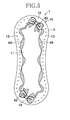
- Fig. 3 shows Example 1 in which graphics are used as an indicator element 61.
- the indicator element 61 seen in Fig. 3 is visually recognized on the first component pad 10.
- the first component pad 10 is formed with the substantially continuous temporarily joined region 13 which is interrupted by the non-joined region 14 as shown in the upper area of Fig.3 as viewed in the longitudinal direction Y.
- Heart marks as the indicator element 61 are provided in the non-joined region 14 so as to be visually recognized through the liquid-absorbent sheet 11. These heart marks facilitate the wearer to recognize the non-joined region 14 and to pinch the peripheral edge 2 in the vicinity of these heart marks with the fingers and thereby to peel off the first component pad 10.
- the first component pad 10 alone is illustrated in this Example 1, it will be understood that the second component pad 20 also is formed in the non-joined region 24 with similar graphics. Thereby, the position of the second component pad 20 to be pinched by the wearer can also be easily recognized. While it is unnecessary to peel off the third component pad 30, the third component pad 30 also may be optionally provided with similar heart marks. In this case, the number of the heart marks may be varied in the order of the first, second and third component pads 10, 20, 30 to make the wearer recognize what number component pad is being used. It should be appreciated that the graphics are not limited to the heart marks and may be selected from various graphics such as snow crystal marks, flower marks, and the like.
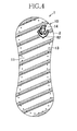
- Fig. 4 is a view similar to Fig. 3 , showing Example 2 wherein a graphic is used as an indicator element 62.
- the first component pad 10 is formed along the peripheral edge 2 with the temporarily joined regions 13 defining the substantially continuous temporarily joined line which is interrupted by non-joined region 14 as shown in the upper area of Fig. 4 .
- an anchor mark is provided as the indicator element 62.
- another pattern is formed so that both the anchor mark and the pattern may be seen through the liquid-absorbent sheet 11.
- the first component pad 10 is formed overall with a striped pattern. Also when the first component pad 10 is formed with the striped pattern, the non-joined region 14 can be easily recognized by forming the first component pad 10 with a graphic distinguished from such striped pattern.
- the second component pad 20 and the third component pad 30 also may be provided with the same indicator element 62 and pattern as those provided on the first component pad 10.
- the pattern and the color thereof on the second component pad 20 and the third component pad 30 may be differentiated form those on the first component pad 10 to ensure that the wearer can identify the respective component pads from one another.
- Fig. 5 is a view similar to Fig. 3 , showing indicator elements 63 used in Example 3.
- the first component pad 10 is formed along transversely opposite side edges with two temporarily joined regions 13, respectively, and two non-joined regions 14 are defined between these two temporarily joined regions 13, as shown in the upper and lower areas of Fig. 5 .
- graphics of knotted ribbon are displayed as the indicator elements 63 and, along the respective temporarily joined regions 13, graphics 64 of ribbon pieces without knots are displayed.
- the presence of graphics 64 displayed along the respective temporarily joined regions 13 assists the wearer to recognize the presence of these temporarily joined regions 13.
- the indicator elements 63 cooperate with the graphics 64 to clarify differences between the non-joined regions 14 and the temporarily joined regions 13 so that the wearer can recognize the non-joined regions 14 more easily.
- the respective graphics 64 it is not essential for the respective graphics 64 to fall precisely on the associated temporarily joined regions 13 and the respective graphics 64 may be sufficiently nearby the associated temporarily joined regions 13 to distinguish the temporarily joined regions 13 from the non-joined regions 14. It is also possible to use flower pieces as the indicator elements 63, for example, and to use graphics of ivy leaves as the graphics 64 so that the indicator elements 63 and the graphics 64 may be meaningfully associated one with another.
- the indicator elements 63 and the graphics 64 used for the first component pad 10 may be used for the second component pad 20 and the third component pad 30 also.
- Fig. 6 illustrates Example 4 wherein a symbol is used as an indicator element 65.
- the first component pad 10 is formed along the peripheral edge 2 with the substantially continuous temporarily joined region 13 which is interrupted by the non-joined region 14 as shown in the upper area of Fig. 6 as viewed in the longitudinal direction Y.
- an arrowhead symbol is displayed as the indicator element 65 serving to indicate the presence of the non-joined region 14.
- the indicator element 65 is not limited to the arrowhead symbol and various symbols other than the arrowhead symbol may be used as the indicator element 65 so far as the non-joined region can be thereby indicated.
- the non-joined region 14 can be indicated with graphics of fingers or triangle.
- the same indicator element 62 and pattern or graphic as those provided on the first component pad 10 may be provided on the second component pad 20 and the third component pad 30 also.
- Fig. 7 illustrates Example 5 wherein the indicator elements are colored so as to be distinguished from other regions.
- the first, second and third component pads 10, 20, 30 are formed along the peripheral edge 2 with the substantially continuous temporarily joined regions 13, 23, 33 which are, in turn, interrupted by the non-joined regions 14, 24, 34, respectively, as shown in the upper area of Fig. 7 .
- one of the opposite ends of the second pad 20 recedes from the corresponding end of the third component pad 30 so that the second component pad 20 has an area smaller than that of the third component pad 30.
- the non-joined region 34 of the third component pad 30 extends outward from underneath and beyond the non-joined region 24 of the second component pad 20.
- Such non-joined region 24 may be colored differently from the other regions to define an indicator element 67.
- first pad 10 recedes from the corresponding end of the second component pad 20 so that the first component pad 10 has an area smaller than that of the second component pad 20.
- the non-joined region 24 of the second component pad 20 extends outward from underneath and beyond the non-joined region 14 of the first component pad 10.
- Such non-joined region 14 is colored differently from the other regions so as to define an indicator element 66. More specifically, this indicator element 66 is colored differently from the indicator element 67 of the second component pad 20.
- the non-joined region 24 of the second component pad 20 extends outward from the non-joined region 14 of the first component pad 10 and the non-joined region 34 of the third component pad 30 extends outward from the non-joined region 24 of the second component pad 20.
- Such arrangement helps the wearer to understand the manner in which these three component pads are layered one on another and to localize the non-joined regions.
- Fig. 8 illustrates Example 6 wherein the pad is formed with cutouts as indicator elements.
- Fig. 8(a) illustrates the state of the composite pad 1 in which the first, second and third component pads 10, 20, 30 are layered one on another
- Fig. 8(b) illustrates the state of the composite pad 1 after the first component pad 10 has been peeled off from the state as illustrated in Fig. 8 (a) .
- the first, second and third component pads 10, 20, 30 are respectively formed along the peripheral edge 2 with the substantially continuous temporarily joined regions 13, 23, 33 which are respectively interrupted by the non-joined regions 14, 24, 34 formed in the upper regions of these component pads, respectively, as viewed in Fig. 8 .
- the first component pad 10 has the non-joined region 14 partially cut away to define the cutout 68.
- the region of the second component pad 20 corresponding to the cutout 68 is colored differently from the other regions to define a colored region 69.
- the colored region 69 can be visually recognized through the cutout 68, i.e., the cutout 6 8 and the colored region 69 cooperate with each other to define the indicator element.
- the second component pad 20 is exposed as the first component pad 10 is peeled off from the composite pad 1 and this second component pad 20 has its non-joined region 24 partially cut away so as to define a cutout 70.
- the region of the third component pad 30 corresponding to the cutout 70 is colored differently from the other regions to define a colored region 71.
- the colored region 71 is visually recognized through the cutout 70, i.e., the colored region 71 and the cutout 70 cooperate with each other to form the indicator element.
- the region 71 may be colored differently from the colored region 69.
- the composite pad 1 according to Example 6 is formed with the cutout regions 68, 70 through which the colored regions 69, 71 of the underlying component pad can be visually recognized. Such arrangement facilitates the non-joined regions 14, 24 to be recognized. It should be understood that the colored regions 69, 71 are not essential features and may be eliminated without departing from the scope of the invention. Even if none of these colored regions 69, 71 is provided, the cutouts 68, 70 effectively assist the wearer to recognize the non-joined regions 14, 24.
- Fig. 9 is a view similar to Fig. 5 , illustrating an indicator element 72 used by Example 7.
- the first component pad 10 is formed along transversely opposite side edges with two temporarily joined regions 13, respectively, and two non-joined regions 14 are defined between these two temporarily joined regions 13 as shown in upper and lower areas of Fig. 9 .
- the regions including none of the indicator elements can be recognized as the non-joined regions 14 merely by displaying the indicator elements 72 in the respective temporarily joined regions 13. Graphics of knot-less ribbon pieces are displayed as the indicator elements 72.
- the indicator elements 72 it is not essential for the indicator elements 72 to fall precisely on the associated temporarily joined regions 13 and the respective graphics 64 may be sufficiently nearby the associated temporarily joined regions 13 to distinguish the temporarily joined regions 13 from the non-joined regions 14. It is possible to use graphics of ivy leaves as the indicator elements 72, for example. These indicator elements 72 preferably include graphics which can be drawn so as to be contiguous one to another so that the regions in which the graphics are interrupted can be recognized as the non-joined regions 14.
- the indicator element may be formed not only by printing or the like technique but also by locally embossing the surfaces of the respective component pads.
- the indicator element may be printed directly on the liquid-absorbent sheet or on the liquid-impervious sheet so that the indicator element can be visually recognized through the liquid-absorbent sheet. It is also possible to use a letter, numeral or the like or a combination of such letters or the like, and a graphic, symbol, pattern or the like as the indicator element.
- the respective Examples have been described on the assumption that each of them is the trilaminar composite pad, the invention is not limited to the trilaminar composite pad and the number of the component pads may be optional so far as the number of the component pads is two or more. However, it is important to temporarily join the respective component pads along the temporarily joined regions 13, 23, 33 without unintentionally being peeled off these component pads from the composite pad put on the wearer's body.
- fibrous non-woven fabric such as spun bond/melt blown/spun bond (SMS) non-woven fabric may be additionally layered on the lower surface of the third component pad 30 and the joining means 40 is provided on this fibrous non-woven fabric.
- the non-woven fabric additionally layered on the third component pad 30 serves as a reinforcing member preventing the third component pad 30 from being damaged in the course of peeling off the third component pad 30 from the wearer's garment such as briefs for the purpose of exchanging the composite pad 1.
- stiffness of the liquid-impervious sheet 32 constituting the third component pad 30 can be reduced and thereby feeling of discomfort which might otherwise be experienced by the wearer during use of the composite pad 1 can be alleviated.
Landscapes
- Health & Medical Sciences (AREA)
- Epidemiology (AREA)
- Engineering & Computer Science (AREA)
- Biomedical Technology (AREA)
- Heart & Thoracic Surgery (AREA)
- Vascular Medicine (AREA)
- Life Sciences & Earth Sciences (AREA)
- Animal Behavior & Ethology (AREA)
- General Health & Medical Sciences (AREA)
- Public Health (AREA)
- Veterinary Medicine (AREA)
- Absorbent Articles And Supports Therefor (AREA)
Abstract
Description
- The present invention generally relates to disposable bodily fluid absorbent composite pads including two or more component pads layered one on another and, more particularly, to such composite pads used, for example, as menstruation napkins, urine absorbent pads or panty liners.
- Disposable bodily fluid absorbent composite pads including two or more component pads layered one on another are known. For example, PATENT CITATION 1 discloses such a composite pad including two or more layered liquid-absorbent component pads temporarily joined together along transversely opposite side edges by locally crimping these layered component pads. Each component pad may be peeled off one by one from a skin-facing side of the composite pad. More specifically, when the component pad contacting the wearer's skin is soiled, it may be peeled off from the remaining components to expose another fresh component pad.
-
- PATENT CITATION 1:
JP 4226086 B2 - The composite pad of the prior art is designed so that the soiled component pad is peeled off from the composite pad by pinching the end portion thereof with the fingers and pulling it off from the composite pad. To ensure the soiled component pad is smoothly peeled off from the composite pad, it is required that the wearer pinches non-crimped region of the composite pad, because it will be difficult to peel off the soiled component pad starting from the crimped region. However, the composite pad is usually of the same color overall and it is difficult for the wearer to catch sight of the non-crimped region instantly.
- An object of the present invention is to provide a disposable bodily fluid absorbent composite pad improved so that the appropriate region to be pinched with the fingers can be easily recognized when it is desired to peel off the soiled component pad from the composite pad.
- The present invention relates to an improvement of a disposable bodily fluid absorbent composite pad having a longitudinal direction and a transverse direction, and including a skin-facing side, a non-skin-facing side opposite to the skin-facing side and two or more component pads each including an upper liquid-absorbent sheet on the skin-facing side and a lower liquid-impervious sheet on the non-skin-facing side and layered one on another.
- The disposable bodily fluid absorbent composite pad is characterized in that:
- the two or more component pads respectively include temporarily joined regions along which the component pads are temporarily joined to each other so as to be peeled off from other component pads and non-joined regions; and
- each of the component pads is formed with an indicator element adapted to be visually recognized through the liquid-absorbent sheet and the indicator elements are formed in the non-joined regions defined along peripheral edges of the component pads and adapted to indicate at least partially the non-joined regions.
- According to one embodiment of the present invention, the temporarily joined regions are formed substantially in continuous fashion along peripheral edges of the component pads and the non-joined regions are defined along partial segments of the peripheral edges so as to interrupt the substantially continuous temporarily joined regions.
- According to another embodiment of the present invention, the indicator element includes at least any one of a letter, a symbol and a graphic displayed in the non-joined regions.
- According to yet another embodiment of the present invention, the indicator element includes at least any one of a letter, a symbol and a graphic serving to indicate the non-joined regions.
- According to still another embodiment of the present invention, the indicator element is defined by coloring of the non-joined regions.
- According to yet another embodiment of the present invention, the indicator element includes cutouts formed by partially cutting away the component pads.
- Two or more liquid-absorbent component pads layered one on another respectively have temporarily joined regions along which these component pads are detachably and temporarily joined together and non-joined regions. The respective component pads are formed with indicator elements adapted to be visually recognized through the associated liquid-absorbent sheets and to indicate the non-joined regions. In this way, the appropriate position of the composite pad to be pinched with the fingers can be easily recognized as instructed by the indicator element.
-
- [
FIG. 1] Fig. 1 is a perspective view of a menstruation napkin. - [
FIG. 2] Fig. 2 is a sectional view taken along line II-II inFig. 1 . - [
FIG. 3] Fig. 3 is a schematic diagram illustrating Example 1. - [
FIG. 4] Fig. 4 is a schematic diagram illustrating Example 2. - [
FIG. 5] Fig. 5 is a schematic diagram illustrating Example 3. - [
FIG. 6] Fig. 6 is a schematic diagram illustrating Example 4. - [
FIG. 7] Fig. 7 is a schematic diagram illustrating Example 5. - [
FIG. 8] Fig. 8 is a schematic diagram illustrating Example 6. - [
FIG. 9] Fig. 9 is a schematic diagram illustrating Example 7. -
- 1
- menstruation napkin (disposable bodily fluid absorbent composite pad)
- 10
- first pad (pad)
- 11
- liquid-absorbent sheet
- 12
- liquid-impervious sheet
- 13
- temporarily joined region
- 14
- non-joined region
- 20
- second pad (pad)
- 21
- liquid-absorbent sheet
- 22
- liquid-impervious sheet
- 23
- temporarily joined region
- 24
- non-joined region
- 30
- third pad (pad)
- 31
- liquid-absorbent sheet
- 32
- liquid-impervious sheet
- 33
- temporarily joined region
- 34
- non-joined region
- 61-63
- indicator elements
- 65-67
- indicator elements
- 68
- cutout
- 69
- colored region
- 70
- cutout
- 71
- colored region
- X
- transverse direction
- Y
- longitudinal direction
- Details of the disposable bodily fluid absorbent composite pad according to the present invention will be described hereunder on the basis of a menstruation napkin as one typical embodiment of the invention. The construction of the menstruation napkin 1 shown in
Figs. 1 and2 is common to Examples 1 through 7.Fig. 1 is a perspective view showing the menstruation napkin 1 as partially cutaway for convenience of illustration andFig. 2 is a sectional view taken along line II-II inFig. 1 . The menstruation napkin 1 has a longitudinal direction Y and a transverse direction X wherein the menstruation napkin 1 is relatively long in the longitudinal direction Y and has a width gradually reduced from longitudinally opposite ends toward a central region. The menstruation napkin 1 has the imaginary longitudinal center line P-P bisecting a width dimension in the transverse direction X and the imaginary transverse center line Q-Q bisecting a length dimension in the longitudinal direction Y. The menstruation napkin 1 is shaped substantially symmetrically about the imaginary longitudinal center line P-P as well as about the imaginary transverse center line Q-Q. - The menstruation napkin 1 has a skin-facing side facing the wearer's body and a non-skin-facing side facing the wearer's garment. The menstruation napkin 1 includes two or more liquid-absorbent component pads layered from the skin-facing side facing the wearer's body to the non-skin-facing side facing the wearer's garment. Specifically, the menstruation napkin 1 includes a
first component pad 10 defining the uppermost layer of the laminate, asecond component pad 20 underlying thefirst component pad 10 and athird component pad 30 underlying thesecond component pad 20. These first, second andthird component pads absorbent sheets impervious sheets absorbent sheets impervious sheets impervious sheets - The non-skin-facing side, i.e., the side facing the wearer's garment, of the
third component pad 30 is formed with joiningmeans 40 such as adhesive which is, in turn, covered from below with areleasable sheet 50. Thereleasable sheet 50 may be peeled off from thethird pad 30 to expose the joining means 40 by the intermediary of which thethird pad 30 may be fastened to the wearer's undergarment. - The first, second and
third component pads releasable sheet 50 are the same in shape as well as in size to one another and respectively have a dimension in the transverse direction X gradually reduced from longitudinally opposite ends toward a central region defined by the imaginary transverse center line Q-Q. By dimensioning thecomponent pads - The first, second and
third component pads peripheral edge 2 thereof with individual temporarily joinedregions regions peripheral edge 2. The depressions are formed by collectively hot-pressing these first, second andthird component pads regions respective component pads - Each of these first, second and
third component pads non-joined region peripheral edge 2 where the temporarily joined region is not formed. In other words, thesenon-joined regions regions non-joined region Fig. 1 but may be formed in other various patterns. Therespective component pads non-joined regions -
Fig. 3 shows Example 1 in which graphics are used as anindicator element 61. Theindicator element 61 seen inFig. 3 is visually recognized on thefirst component pad 10. Thefirst component pad 10 is formed with the substantially continuous temporarily joinedregion 13 which is interrupted by thenon-joined region 14 as shown in the upper area ofFig.3 as viewed in the longitudinal direction Y. Heart marks as theindicator element 61 are provided in thenon-joined region 14 so as to be visually recognized through the liquid-absorbent sheet 11. These heart marks facilitate the wearer to recognize thenon-joined region 14 and to pinch theperipheral edge 2 in the vicinity of these heart marks with the fingers and thereby to peel off thefirst component pad 10. - While the
first component pad 10 alone is illustrated in this Example 1, it will be understood that thesecond component pad 20 also is formed in thenon-joined region 24 with similar graphics. Thereby, the position of thesecond component pad 20 to be pinched by the wearer can also be easily recognized. While it is unnecessary to peel off thethird component pad 30, thethird component pad 30 also may be optionally provided with similar heart marks. In this case, the number of the heart marks may be varied in the order of the first, second andthird component pads -
Fig. 4 is a view similar toFig. 3 , showing Example 2 wherein a graphic is used as anindicator element 62. Thefirst component pad 10 is formed along theperipheral edge 2 with the temporarily joinedregions 13 defining the substantially continuous temporarily joined line which is interrupted bynon-joined region 14 as shown in the upper area ofFig. 4 . In thenon-joined region 14, an anchor mark is provided as theindicator element 62. In this Example, in addition to the anchor mark as theindicator element 62, another pattern is formed so that both the anchor mark and the pattern may be seen through the liquid-absorbent sheet 11. Specifically, thefirst component pad 10 is formed overall with a striped pattern. Also when thefirst component pad 10 is formed with the striped pattern, thenon-joined region 14 can be easily recognized by forming thefirst component pad 10 with a graphic distinguished from such striped pattern. - Similarly to Example 1, the
second component pad 20 and thethird component pad 30 also may be provided with thesame indicator element 62 and pattern as those provided on thefirst component pad 10. In this case, the pattern and the color thereof on thesecond component pad 20 and thethird component pad 30 may be differentiated form those on thefirst component pad 10 to ensure that the wearer can identify the respective component pads from one another. -
Fig. 5 is a view similar toFig. 3 , showingindicator elements 63 used in Example 3. Thefirst component pad 10 is formed along transversely opposite side edges with two temporarily joinedregions 13, respectively, and twonon-joined regions 14 are defined between these two temporarily joinedregions 13, as shown in the upper and lower areas ofFig. 5 . In the respectivenon-joined regions 14, graphics of knotted ribbon are displayed as theindicator elements 63 and, along the respective temporarily joinedregions 13,graphics 64 of ribbon pieces without knots are displayed. - The presence of
graphics 64 displayed along the respective temporarily joinedregions 13 assists the wearer to recognize the presence of these temporarily joinedregions 13. Theindicator elements 63 cooperate with thegraphics 64 to clarify differences between thenon-joined regions 14 and the temporarily joinedregions 13 so that the wearer can recognize thenon-joined regions 14 more easily. - It should be appreciated that it is not essential for the
respective graphics 64 to fall precisely on the associated temporarily joinedregions 13 and therespective graphics 64 may be sufficiently nearby the associated temporarily joinedregions 13 to distinguish the temporarily joinedregions 13 from thenon-joined regions 14. It is also possible to use flower pieces as theindicator elements 63, for example, and to use graphics of ivy leaves as thegraphics 64 so that theindicator elements 63 and thegraphics 64 may be meaningfully associated one with another. Theindicator elements 63 and thegraphics 64 used for thefirst component pad 10 may be used for thesecond component pad 20 and thethird component pad 30 also. -
Fig. 6 illustrates Example 4 wherein a symbol is used as anindicator element 65. Thefirst component pad 10 is formed along theperipheral edge 2 with the substantially continuous temporarily joinedregion 13 which is interrupted by thenon-joined region 14 as shown in the upper area ofFig. 6 as viewed in the longitudinal direction Y. In the vicinity of thenon-joined region 14, an arrowhead symbol is displayed as theindicator element 65 serving to indicate the presence of thenon-joined region 14. - The
indicator element 65 is not limited to the arrowhead symbol and various symbols other than the arrowhead symbol may be used as theindicator element 65 so far as the non-joined region can be thereby indicated. For example, thenon-joined region 14 can be indicated with graphics of fingers or triangle. As in the case of Example 1, thesame indicator element 62 and pattern or graphic as those provided on thefirst component pad 10 may be provided on thesecond component pad 20 and thethird component pad 30 also. -
Fig. 7 illustrates Example 5 wherein the indicator elements are colored so as to be distinguished from other regions. The first, second andthird component pads peripheral edge 2 with the substantially continuous temporarily joinedregions non-joined regions Fig. 7 . As shown in the upper area ofFig. 7 , one of the opposite ends of thesecond pad 20 recedes from the corresponding end of thethird component pad 30 so that thesecond component pad 20 has an area smaller than that of thethird component pad 30. In other words, thenon-joined region 34 of thethird component pad 30 extends outward from underneath and beyond thenon-joined region 24 of thesecond component pad 20. Suchnon-joined region 24 may be colored differently from the other regions to define anindicator element 67. - As shown in the upper area of
Fig. 7 , one of the opposite ends offirst pad 10 recedes from the corresponding end of thesecond component pad 20 so that thefirst component pad 10 has an area smaller than that of thesecond component pad 20. In other words, thenon-joined region 24 of thesecond component pad 20 extends outward from underneath and beyond thenon-joined region 14 of thefirst component pad 10. Suchnon-joined region 14 is colored differently from the other regions so as to define anindicator element 66. More specifically, thisindicator element 66 is colored differently from theindicator element 67 of thesecond component pad 20. - In the menstruation napkin 1 as has been heretofore described, the
non-joined region 24 of thesecond component pad 20 extends outward from thenon-joined region 14 of thefirst component pad 10 and thenon-joined region 34 of thethird component pad 30 extends outward from thenon-joined region 24 of thesecond component pad 20. Such arrangement helps the wearer to understand the manner in which these three component pads are layered one on another and to localize the non-joined regions. -
Fig. 8 illustrates Example 6 wherein the pad is formed with cutouts as indicator elements. Specifically,Fig. 8(a) illustrates the state of the composite pad 1 in which the first, second andthird component pads Fig. 8(b) illustrates the state of the composite pad 1 after thefirst component pad 10 has been peeled off from the state as illustrated inFig. 8 (a) . The first, second andthird component pads peripheral edge 2 with the substantially continuous temporarily joinedregions non-joined regions Fig. 8 . - As shown in upper area of
Fig. 8(a) , thefirst component pad 10 has thenon-joined region 14 partially cut away to define thecutout 68. The region of thesecond component pad 20 corresponding to thecutout 68 is colored differently from the other regions to define acolored region 69. In this way, thecolored region 69 can be visually recognized through thecutout 68, i.e., the cutout 6 8 and thecolored region 69 cooperate with each other to define the indicator element. - The
second component pad 20 is exposed as thefirst component pad 10 is peeled off from the composite pad 1 and thissecond component pad 20 has itsnon-joined region 24 partially cut away so as to define acutout 70. The region of thethird component pad 30 corresponding to thecutout 70 is colored differently from the other regions to define acolored region 71. With such an arrangement, thecolored region 71 is visually recognized through thecutout 70, i.e., thecolored region 71 and thecutout 70 cooperate with each other to form the indicator element. Theregion 71 may be colored differently from thecolored region 69. - The composite pad 1 according to Example 6 is formed with the
cutout regions colored regions non-joined regions colored regions colored regions cutouts non-joined regions -
Fig. 9 is a view similar toFig. 5 , illustrating anindicator element 72 used by Example 7. Thefirst component pad 10 is formed along transversely opposite side edges with two temporarily joinedregions 13, respectively, and twonon-joined regions 14 are defined between these two temporarily joinedregions 13 as shown in upper and lower areas ofFig. 9 . In this Example, the regions including none of the indicator elements can be recognized as thenon-joined regions 14 merely by displaying theindicator elements 72 in the respective temporarily joinedregions 13. Graphics of knot-less ribbon pieces are displayed as theindicator elements 72. - It should be appreciated that it is not essential for the
indicator elements 72 to fall precisely on the associated temporarily joinedregions 13 and therespective graphics 64 may be sufficiently nearby the associated temporarily joinedregions 13 to distinguish the temporarily joinedregions 13 from thenon-joined regions 14. It is possible to use graphics of ivy leaves as theindicator elements 72, for example. Theseindicator elements 72 preferably include graphics which can be drawn so as to be contiguous one to another so that the regions in which the graphics are interrupted can be recognized as thenon-joined regions 14. - In the respective Examples, the indicator element may be formed not only by printing or the like technique but also by locally embossing the surfaces of the respective component pads. When the printing or the like technique is employed, the indicator element may be printed directly on the liquid-absorbent sheet or on the liquid-impervious sheet so that the indicator element can be visually recognized through the liquid-absorbent sheet. It is also possible to use a letter, numeral or the like or a combination of such letters or the like, and a graphic, symbol, pattern or the like as the indicator element. While the respective Examples have been described on the assumption that each of them is the trilaminar composite pad, the invention is not limited to the trilaminar composite pad and the number of the component pads may be optional so far as the number of the component pads is two or more. However, it is important to temporarily join the respective component pads along the temporarily joined
regions - In the lowermost
third component pad 30, fibrous non-woven fabric such as spun bond/melt blown/spun bond (SMS) non-woven fabric may be additionally layered on the lower surface of thethird component pad 30 and the joiningmeans 40 is provided on this fibrous non-woven fabric. The non-woven fabric additionally layered on thethird component pad 30 serves as a reinforcing member preventing thethird component pad 30 from being damaged in the course of peeling off thethird component pad 30 from the wearer's garment such as briefs for the purpose of exchanging the composite pad 1. By using the fibrous non-woven fabric as the reinforcing member, stiffness of the liquid-impervious sheet 32 constituting thethird component pad 30 can be reduced and thereby feeling of discomfort which might otherwise be experienced by the wearer during use of the composite pad 1 can be alleviated.
Claims (6)
- A disposable bodily fluid absorbent composite pad having a longitudinal direction and a transverse direction and comprising a skin-facing side and a non-skin-facing side opposite to the skin-facing side and two or more component pads each including an upper liquid-absorbent sheet on the skin-facing side and a lower liquid-impervious sheet on the non-skin-facing side and layered one on another, wherein:the two or more component pads respectively comprise temporarily joined regions along which the component pads are temporarily joined to each other so as to be peeled off from other component pads and non-joined regions; andeach of the component pads is formed with an indicator element adapted to be visually recognized through the liquid-absorbent sheet and the indicator elements are formed in the non-joined regions defined along peripheral edges of the component pads and adapted to indicate at least partially the non-joined regions.
- The disposable bodily fluid absorbent composite pad defined by Claim 1, wherein the temporarily joined regions are formed substantially in continuous fashion along peripheral edges of the component pads and the non-joined regions are defined along partial segments of the peripheral edges so as to interrupt the substantially continuous temporarily joined regions.
- The disposable bodily fluid absorbent composite pad defined by Claim 1 or 2, wherein the indicator element comprises at least any one of a letter, a symbol and a graphic displayed in the non-joined regions.
- The disposable bodily fluid absorbent composite pad defined by any one of Claims 1 through 3, wherein the indicator element comprises at least any one of a letter, a symbol and a graphic serving to indicate the non-joined regions.
- The disposable bodily fluid absorbent composite pad defined by any one of Claims 1 through 4, wherein the indicator element is defined by coloring of the non-joined regions.
- The disposable bodily fluid absorbent composite pad defined by any one of Claims 1 through 5, wherein the indicator element comprises cutouts formed by partially cutting away the component pads.
Applications Claiming Priority (1)
| Application Number | Priority Date | Filing Date | Title |
|---|---|---|---|
| PCT/JP2009/063444 WO2011013208A1 (en) | 2009-07-28 | 2009-07-28 | Disposable composite pad for treating body fluid |
Publications (2)
| Publication Number | Publication Date |
|---|---|
| EP2460497A1 true EP2460497A1 (en) | 2012-06-06 |
| EP2460497A4 EP2460497A4 (en) | 2014-03-12 |
Family
ID=43528885
Family Applications (1)
| Application Number | Title | Priority Date | Filing Date |
|---|---|---|---|
| EP09847800.1A Withdrawn EP2460497A4 (en) | 2009-07-28 | 2009-07-28 | Disposable composite pad for treating body fluid |
Country Status (5)
| Country | Link |
|---|---|
| US (1) | US20110319854A1 (en) |
| EP (1) | EP2460497A4 (en) |
| JP (1) | JP5717340B2 (en) |
| CN (1) | CN102481213A (en) |
| WO (1) | WO2011013208A1 (en) |
Families Citing this family (9)
| Publication number | Priority date | Publication date | Assignee | Title |
|---|---|---|---|---|
| RU2628887C1 (en) * | 2013-11-06 | 2017-08-22 | Ска Хайджин Продактс Аб | Absorbent product containing more than one hygroscopic pads stacked in pile |
| FR3024945B1 (en) * | 2014-08-21 | 2018-03-23 | The Procter & Gamble Company | ABSORBENT ARTICLE WITH GRAPHICS |
| EP3294247A1 (en) * | 2015-05-14 | 2018-03-21 | The Procter and Gamble Company | Absorbent article with graphic framing |
| AU2015414699B2 (en) * | 2015-11-19 | 2018-10-04 | Essity Hygiene And Health Aktiebolag | Absorbent article |
| MY201037A (en) * | 2018-07-02 | 2024-01-31 | Unicharm Corp | Absorbent-article package piece and package for absorbent-article package piece |
| WO2020009236A1 (en) * | 2018-07-06 | 2020-01-09 | ユニ・チャーム株式会社 | Absorbent article, absorbent article individual packaging, individual packaging assembly, and individual packaging package |
| JP7117919B2 (en) * | 2018-07-06 | 2022-08-15 | ユニ・チャーム株式会社 | absorbent article |
| JP7117920B2 (en) * | 2018-07-06 | 2022-08-15 | ユニ・チャーム株式会社 | Individual packages of absorbent articles, aggregates of individual packages, and storage packages for individual packages |
| US11969326B2 (en) * | 2019-01-15 | 2024-04-30 | Medline Industries, Lp | Multilayer bladder control pad |
Family Cites Families (13)
| Publication number | Priority date | Publication date | Assignee | Title |
|---|---|---|---|---|
| US2929379A (en) * | 1957-07-08 | 1960-03-22 | Poulsen Else Vita | Sanitary napkin |
| JP2810215B2 (en) * | 1990-06-15 | 1998-10-15 | 株式会社平野屋物産 | Easy opening plastic bag |
| US5599339A (en) * | 1995-10-31 | 1997-02-04 | The Procter & Gamble Company | Absorbent article |
| JP2899795B2 (en) * | 1996-02-08 | 1999-06-02 | 充加 貫名 | Multilayer sanitary article, method for producing the same, and composite absorbent sheet for multilayer sanitary article |
| JP4226086B2 (en) | 1996-02-08 | 2009-02-18 | 充加 貫名 | Multi layer sanitary products |
| JP2001187084A (en) * | 1996-02-08 | 2001-07-10 | Michika Nukina | Multi-layer sanitary products |
| JPH10286280A (en) * | 1997-02-17 | 1998-10-27 | Asubii:Kk | Sanitary laminated napkin |
| US6013064A (en) * | 1997-02-17 | 2000-01-11 | Asbe Co., Ltd. | Multi-layer sanitary napkin |
| NZ314792A (en) * | 1997-02-17 | 1998-05-27 | Asbe Co Ltd | Sanitary napkin comprises stack of separate absorbent pads peelably united at periphery |
| JP4107414B2 (en) * | 2002-07-01 | 2008-06-25 | 花王株式会社 | Multi-layer absorbent article |
| JP4738049B2 (en) * | 2005-05-02 | 2011-08-03 | ユニ・チャーム株式会社 | Absorbent articles |
| EP1779874A1 (en) * | 2005-10-26 | 2007-05-02 | The Procter & Gamble Company | Sanitary article with ink to increase the hydrophobicity of certain area |
| JP5028816B2 (en) * | 2006-02-17 | 2012-09-19 | 大日本印刷株式会社 | Adhesive sheet with release sheet |
-
2009
- 2009-07-28 JP JP2009532476A patent/JP5717340B2/en active Active
- 2009-07-28 WO PCT/JP2009/063444 patent/WO2011013208A1/en not_active Ceased
- 2009-07-28 CN CN2009801613062A patent/CN102481213A/en active Pending
- 2009-07-28 EP EP09847800.1A patent/EP2460497A4/en not_active Withdrawn
- 2009-07-28 US US12/525,040 patent/US20110319854A1/en not_active Abandoned
Also Published As
| Publication number | Publication date |
|---|---|
| WO2011013208A1 (en) | 2011-02-03 |
| US20110319854A1 (en) | 2011-12-29 |
| JPWO2011013208A1 (en) | 2013-01-07 |
| JP5717340B2 (en) | 2015-05-13 |
| CN102481213A (en) | 2012-05-30 |
| EP2460497A4 (en) | 2014-03-12 |
Similar Documents
| Publication | Publication Date | Title |
|---|---|---|
| US20110319854A1 (en) | Disposable bodily fluid handling composite pad | |
| US20050261653A1 (en) | Absorbent article having a fit guide | |
| US20050261652A1 (en) | Method for proper placement and positioning of an absorbent article in an undergarment | |
| JP5010478B2 (en) | Absorbent articles | |
| EP1755518B1 (en) | Absorbent article having a fit guide | |
| EP2394621B1 (en) | Disposable bodily fluent absorbent wearing article | |
| JP4243063B2 (en) | Absorbent article and manufacturing method thereof | |
| MX2012012348A (en) | Feminine hygiene pads. | |
| JP4252226B2 (en) | Disposable diapers | |
| EP2460496A1 (en) | Disposable composite pad for bodily fluid | |
| JP2010227286A (en) | Sanitary napkin | |
| JP5486290B2 (en) | Absorbent articles | |
| JP2011136099A (en) | Individual packaging body for absorptive article | |
| JP4317880B2 (en) | Tape-type paper diapers | |
| AU2009324278A1 (en) | Disposable bodily fluid handling composite pad | |
| JP4852090B2 (en) | Absorbent article and manufacturing method thereof | |
| JP4558080B1 (en) | Absorbent articles | |
| JP2021020009A (en) | Absorbent article | |
| JP5969156B1 (en) | Breastfeeding pad | |
| AU2009329563A1 (en) | Disposable bodily fluid handling composite pad | |
| CN216417543U (en) | Absorbent article, individual package of absorbent article, assembly of individual packages, and storage package of individual packages | |
| JP2012085800A (en) | Absorbent article | |
| CN119700428A (en) | Absorbent articles | |
| JP5479221B2 (en) | Absorbent articles | |
| JP3196243U (en) | Absorbent articles with wings |
Legal Events
| Date | Code | Title | Description |
|---|---|---|---|
| PUAI | Public reference made under article 153(3) epc to a published international application that has entered the european phase |
Free format text: ORIGINAL CODE: 0009012 |
|
| 17P | Request for examination filed |
Effective date: 20120130 |
|
| AK | Designated contracting states |
Kind code of ref document: A1 Designated state(s): AT BE BG CH CY CZ DE DK EE ES FI FR GB GR HR HU IE IS IT LI LT LU LV MC MK MT NL NO PL PT RO SE SI SK SM TR |
|
| DAX | Request for extension of the european patent (deleted) | ||
| A4 | Supplementary search report drawn up and despatched |
Effective date: 20140206 |
|
| RIC1 | Information provided on ipc code assigned before grant |
Ipc: A61F 13/505 20060101ALI20140131BHEP Ipc: A61F 13/513 20060101ALI20140131BHEP Ipc: A61F 13/472 20060101ALI20140131BHEP Ipc: A61F 13/47 20060101ALI20140131BHEP Ipc: A61F 13/84 20060101ALI20140131BHEP Ipc: A61F 13/15 20060101AFI20140131BHEP Ipc: A61F 13/539 20060101ALI20140131BHEP |
|
| STAA | Information on the status of an ep patent application or granted ep patent |
Free format text: STATUS: THE APPLICATION HAS BEEN WITHDRAWN |
|
| 18W | Application withdrawn |
Effective date: 20140410 |